英文规格书格式
贴片物料规格书样本(英文版)(pdf 9页)
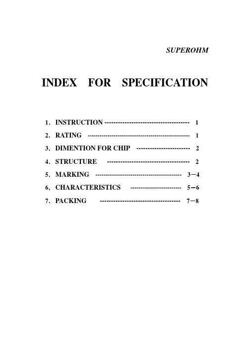
SUPEROHM INDEX FOR SPECIFICATION1.INSTRUCTION -------------------------------------- 1 2.RATING ---------------------------------------------------- 1 3.DIMENTION FOR CHIP ------------------------ 2 4.STRUCTURE ------------------------------------- 2 5.MARKING -------------------------------------------- 3-4 6.CHARACTERISTICS -------------------------- 5-6 7.PACKING ------------------------------------ 7-8VOLTAGE RA TING:RESISTORS SHALL HAVE A RATED DIRECT-CURRENT (DC) CONTINUOUS WORKING VOLTAGE OR AN APPROXIMATE SINE-WAVE ROOT-MEAN-SQUARE (RMS)DIMENSION FOR CHIP:DIMENSION: mm TYPE L W H l11.00 ± 0.10+ 0.050.50- 0.050.35 ± 0.05 0.20 ± 0.101.60 ± 0.10+ 0.150.80 0.45 ± 0.10 0.30 ± 0.20THICK FILM CHIP RESISTORS5. MARKING:(1) FOR 0402 SIZE. DUE TO THE VERY SMALL SIZE OF THE RESISTOR’S BODY, THERE ISNO MARKING ON THE BODY.(2) ±5% TOLERANCE: THE FIRST TWO DIGITS ARE SIGNIFICANT FIGUTRES OF RESISTANCE AND THE THIRD DENOTES NUMBER OF ZEROS FOLLOWINGEXAMPLE:33000 → 33KΩ(3) ±5% TOLERANCE: BELOW 10Ω SHOW AS FOLLOWINGEXAMPLE:2.2Ω(4) ±1% TOLERANCE: 4 DIGITS, FIRST THREE DIGITS ARE SIGNIFICANT, FORTH DIGIT IS NUMBER OF ZEROS. LETTER R IS DECIMAL POINT.EXAMPLE:2700 → 2.7KΩ10.5Ω(5) STANDARD E-96 SERIES VALUES (±1% TOLERANCE) OF 0603 SIZE. DUE TH THE SMALL SIZE OF THE RESISTOR’S BODY, 3 DIGITS MARKING WILL BE USED TO INDICATE THE ACCUATE RESISTANCE VAUE BY USING THE FOLLOWING MULTIPLIER & RESISTANCE CODE.MULTIPLIER CODE:CODE A B C D E F G H X Y Z MULTIPLIER 100 101 102103104105106107 10-1 10-210-3CODING FORMULAFIRST TWO DIGITS------------RESISTANCE CODETHIRD DIGIT-------------------MULTIPLIER CODEEXAMPLE : 1.96KΩ=196×101Ω=29B 12.4Ω=124×10-1Ω=10XCHARACTERISTIC LIMITSTEST METHOD (JIS-C-5201/5202)7.4 RESISTANCE CHANGE AFTERCONTINUOUS FIVE CYCLES FOR DUTY CYCLE SPECIFIED BELOW:STEP TEMPERATURE TIME ±1%±(0.5%+0.05 Ω)MAX1-55℃ ± 3℃30 MINS 2 ROOM TEMP .10 --- 15 MINS 3+155℃ ± 3℃30 MINS TEMPERATURECYCLING±5%±(1.0%+0.05 Ω)MAX.4 ROOM TEMP .10 --- 15 MINSSOLDERABILITY 95% COVERAGE MIN.6.5 TEST TEMPERATURE OF SOLDER: 245°C ± 5°C DIPPING TIME IN SOLDER: 3± 0.5 SECONDS.±1%±( 0.5%+0.1 Ω ) MAX.HUMIDITY ( STEADY STATE )±5%±( 3.0%+0.1 Ω ) MAX.7.5 TEMPORARY RESISTANCE CHANGE AFTER A 1,000 HOURS EXPOSURE IN A HUMIDITY CHAMBER.RESISTANCE CHANGE RATE IS:±1% ±(1%+0.1Ω ) MAX. LOAD LIFE IN HUMIDITY±5%±(3%+0.1Ω ) MAX.7.9 RESISTANCE CHANGE AFTER 1,000HOURS (1.5 HOURS “ON”,0.5 HOUR “OFF”) AT RCWV IN A HUMIDITYCHAMBER CONTROLLED AT 40℃±2℃ AND 90 TO 95% RELATIVE HUMIDITY .RESISTANCE CHANGE RATE IS:±1% ±(1%+0.1Ω) MAX.LOAD LIFE±5% ±(3%+0.1Ω) MAX.7.10 PERMANENT RESISTANCE CHANGE AFTER 1,000 HOURS OPERATING AT RCWV WITH DUTYCYCLE 1.5 HOURS “ON”, 0.5 HOUR “OFF” AT 70℃±2℃ AMBIENT.TAPPING DIMENSION:UNIT: mm DIMENSION:TYPE TAPING QUANTITY A±0.5B±0.5 C±0.5DPAPER 10,000 PCS REEL 2.0 13.0 21.0 60.0PAPER 5,000 PCS REEL 2.0 13.0 21.0 60.0。
中英文版泵规格书(非常规范)

( )
kW
26
Min.flow check valve
最小流量止回阀
/no
/无
Self priming自吸
/ no
/无
27
Construction Features结构特征
28
Rateddesignpressure
额定设计压力
required
要求
16
barg
60
°C
TotalClearance
Type型号:
Orderer订货商:
Manufacturer制造商:
Inquiry No.询价号.:
Offer No.供应号.:
Order No.订货号.:
Job No.项目号.:
Issue
版本
State阶段
Date
日期
Prepared
准备
Checked
检查
Approved
批准
Remark
备注
11
Server for plant: Air seperation plant2Plant
Total weight incl. Driver
包括电机的总重量
()
kg
49
Remarks:(1) *) viewed from driver to pump**) viewed from pump to driver
kW
22
normal
正常
619.8
m³/h
normal
正常
( )
kW
23
minimum
最小
479.3
m³/h
maximum
产品承认书.8doc之英文版规格书
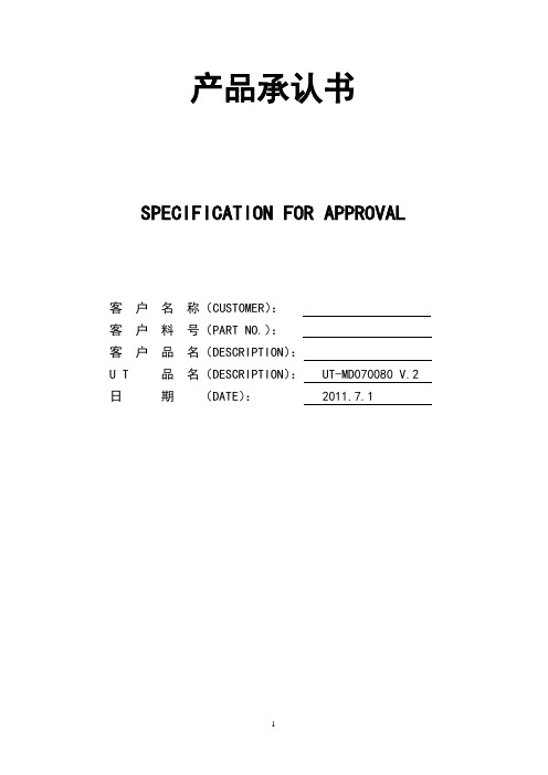
产品承认书SPECIFICATION FOR APPROVAL客户名称(CUSTOMER):客户料号(PART NO.):客户品名(DESCRIPTION):U T 品名(DESCRIPTION): UT-MD070080 V.2 日期(DATE): 2011.7.1CONTENTS contents (2)Change description (3)1. Scope of application (3)2. Product Function Description (3)3. Standard Signal Input (3)4. Work Temp (3)5. Storage Temp (3)6. Operate Power Requirements (3)7. Specification (4)8. Power supply (9)9. Electrical parameters (9)10. LCD Specifications (9)11. Electrical circuit (10)12. Basic operating instructions (10)13. Testing equipment (12)14. Function test (12)15. Reliability test (14)16. Outgoing inspection standards (14)1. Scope of applicationThis standard applies to production for:AT080TN42.AT080TN01.AT080TN03.AT070TN83V.3.AT070TN82 V.1. AT102TN01.AT102TN03.A101VW01..AT080TN52.AT070TN92LCD display module driver board UT-MD070080 V.2 Inspection。
英文技术规格书范文
英文技术规格书范文Here's an example of a technical specification written in an informal and conversational English style, with each paragraph maintaining independence and variety in language characteristics:The gizmo is seriously cool. It's small enough to fitin your palm, but don't let its size fool you. This little device packs a punch. It's made from a lightweight but super-durable material that can take a few bumps and bruises without breaking a sweat.The gizmo's interface is seriously user-friendly. You don't need to be a tech wizard to figure it out. Just a few taps and swipes, and you're good to go. The screen isbright and clear, making it easy to see even in bright sunlight.One of the coolest features of the gizmo is its battery life. You can use it for hours on a single charge, so youdon't have to worry about it running out of juice mid-task. And when it does need a recharge, it's quick and painless.But wait, there's more! The gizmo is also compatible with a ton of different devices and software. So, whether you're using it with your phone, laptop, or even your smartwatch, it'll work seamlessly. No need to worry about compatibility issues here.Overall, the gizmo is a great choice for anyone looking for a compact, powerful, and user-friendly device. It's got everything you need and nothing you don't, making it a top pick in its category. So, if you're in the market for a new gizmo, give this one a serious look.。
电子产品中英文规格书完整版

Page 1 Of 12 ShenZhen C&D Electronics CO.Ltd.Add: Building 2, Xiayousong Mountaintop Industrial District,Yousong Village,LongHua Town, Baoan District ShenZhen China Zip 518109Tel: 86-755- 28142422 Fax: 86-755-28142699 E-mail:****************** Remote control specification(Rev. A0)Seller CustomerPart Name :Remote control Part No. : Part Name : Part No. :Seller approval Customer approvalPrepared By: Date:Received by: Date:Checked By: Date: Checked by: Date:Approved By: Date:Approved by: Date:company chop:company chop:Change historyVersion Date Description AuthorPage 2 Of 12 2、目录Index3.检验内容及要求(Verification content & Requirement) Page 3Of 121、一般项目(General Items)1.1、适用范围Apply for: RC35J remote1.2、工作环境Working Environment: -10℃~40℃、45﹪~90﹪RH、86~106Kpa1.3、存储温度Storage Temperature :-40℃~70℃1.4、试验环境Test Environment: 5℃~35℃、45﹪~75﹪RH、86~106Kpa1.5、额定电压Rating Voltage:DC3.0V1.6、适用电池Power: AAA*2 pcs1.7、重量范围:25g +/-5g(Extra weight is 25g +/-5g)2、可视检测项目Visible Test Item测试条件Test ConditionsA:正面在标准光源下30CM距离10秒以内目测Put the top face under the standard light source and test by sight from the 30cm distance for 10 secondsB:其余面标准光源下50CM距离5秒以内目测Put other sides under the standard light source and test by sight from the 50cm distance for 5 seconds序号No.项目Item测试要求Test Requirements2.1划伤、沾污、割裂、变形Scratches, Stain and distortion of the Unit符合摩托罗拉规格书365-095-08990According to Moto specification, 365-095-089902.2印刷图形及文字Hot Stamped Graphics and Letters 内容正确、清晰、均匀、整齐Correct, in focus and comply With the drawing2.3壳体配合Match of top case and bottom case 无翘起、变形、开裂、断差No distortion and Crack between the two parts2.4表面Appearance材质正确、顔色一致Correct material and color3、电气性能Electric Capability序号项目测试要求Test Requirements3.1载波频率Carrier frequency36KHZ ±1K3.2工作电压Working Voltage DC2.2V~3.6V3.3待机电流Static Current≤5uA3.4工作电流Working Current≤50mA3.5发射角度和距离Transmit Angel and Distance (工作电压3.0V)Working Voltage(3V)3.6码表Code Table见码表图Refer to the Code Table 3.7工作原理图Schematic Diagram见工作原理图Schematic DiagramPage 6Of 12Page 7Of 12 4、码表(Code tableve )Page 8Of 12 5、产品效果图(Product Cosmetics drawing)6. 原理图(Schematic diagram) Page 9Of 12Page10Of 12 7、爆炸图(Explosion drawing)Page 11Of 12 8、产品尺寸图(Dimension drawing)9、包装尺寸图(Packaging drawing) Page 12 Of 12 Label inside Battery door:Label for PE plastic package: Lable for carton box:Packing drawing:。
规格书英文版模板
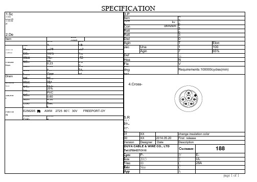
30V 0.5kv/1min (AC) Tensile Strength(min.)Elongation(min.) 1.05kg/mmsq 100% 70% ### ≦50% No damage VW-1 Requirements:100000cycles(min)
P1 1 2 3 4
Remark
Conductor resistance Rating Temperature Rating Voltage Dielectric strength Aging test Jacket Unaged Aging(113℃x168h) Deformation(121℃) Heat shock(121℃x1h) Flame test
page 1 of 1
188
Spec. No. Issue Date Version Edited Approved
P-188-2725-016 2013/11/11 00 Niton Li
E-W05-2800601043101 P/N: UL AWM style 2725 Title Construction 28AWG*1P+28AWG*4C+D+AL Checked Approved
SPECIFICATION
1.Scope:
This specification established a description for a HD-PE insulation,
3.Physical and Electrical Performance
Item Spark Test Requirement kv 1.0 for insulation; 3.0 for jacket ohm/km 237.25(at 20℃max ) 80℃
2835规格书
C62 N13 C63
0.34
C32 C43 C33
0.32
0.3 0.3 0.32 0.34 0.36 0.38 0.4 0.42 0.44 0.46
X
SPEC NO:B-13-A-0740
REV NO: A/3
DATE: MAR/04/2015
PAGE: 7 OF 14
HL-A-2835H431W-S1-08-HR3
Electrical / Optical Characteristics at Ta=25°C
Parameter(参数) Forward Voltage 正向电压 Viewing Angle 角度 Color Rendering Index 显色性指数 Reverse Current 反向电流 Symbol (符号) VF 2θ1/2 Ra IR Min. (最小) 2.8 -80 -Typ. (平均) -120 ---
RoHS
Specification
规 格 书
Customer Name:
客户名称:
Customer P/N:
客户品号:
Factory P/N: HL-A-2835H431W-S1-08-HR3
公司品号:
Sending Date:
送样日期:
Client approval
客户审核
Hongli approval
SPEC NO:B-13-A-0740
REV NO: A/3
DATE: MAR/04/2015
PAGE: 5 OF 14
HL-A-2835H431W-S1-08-HR3
Typical optical characteristics curves 典型光学特性曲线
技术规格书(中英文)
技术规格书(中英⽂)NPC-National Petro Co.3600t Revolving/Engineering CraneTechnical Specification (Project Plan)Shanghai Zhenhua Port Machinery (Group) Co., Ltd.2005-12-10Table of Content1.1 General Description 总则1.1.1Consist of the Specification 本规格书组成The specification including general, hull structure, outfitting, machinery, electrical, refrigerating, air conditioning, ventilating, pipelaying, DP, and crane parts describes the 3600t CRANE PIPELAYING VESSEL based on scheme design.本规格书由船舶总体、舾装、轮机、电⽓、通风冷藏空调、动⼒定位、起重机及铺管设备估价等部分组成,表述3600 t全回转起重⼯程船的主要技术规格⽅案。
1.1.2Construction Explanation建造说明The BUILDER’s supply covers the item described in this specification, anything excluding from the scope of the specification will be supplied by the OWNER.本船的建造估价,所有规格书所规定的项⽬均由建造⽅提供。
超过规格书部分船东提供。
1.1.3Language and Measuring Unit⽂种与计量单位The drawings, instructions, instruments, display, caution sign and nameplate shall be written in English and kept down the foreign nameplate of the importation of machine and equipments. Metric system is used for designing and fabricating of hull, crane and equipment etc. unless otherwise specialized in specification or instruction.本船的图纸、使⽤说明书、仪表、显⽰、警⽰牌和铭牌等均以英⽂书写。
英文产品规格书
英文产品规格书Product Specifications: A Comprehensive GuideIntroductionProduct specifications are essential documents that outline the detailed information about a product. They serve as a reference for manufacturers, suppliers, and customers, ensuring that the product is designed, developed, and manufactured to meet specific requirements. This article will provide a comprehensive guide on how to create an effective English product specifications document, covering all the necessary aspects.1. Product DescriptionThe product description section should provide a clear and concise overview of the product, including its name, purpose, and target market. It should also include any key features or unique selling points that differentiate the product from competitors. For example, if the product is a smartphone, the description should mention its brand, model, operating system, screen size, and any other relevant specifications.2. Technical SpecificationsThis section focuses on the technical details of the product and provides in-depth information. It should cover all the components and functionalities of the product. For example, if the product is a laptop, the technical specifications should include details such as processor type and speed, RAM size, storage capacity, screen resolution, battery life, and connectivity options.3. Physical DimensionsThis section provides the physical measurements of the product, including its size, weight, and dimensions. It is essential for manufacturers and distributors to understand the product's physical characteristics for packaging, shipping, and storage purposes. This information helps customers visualize the product and determine whether it fits their requirements.4. Material and ConstructionIn this section, specify the materials used in the product's construction. This includes both the primary material and any additional components or accessories. For example, if the product is a car, mention the type of metal used for the body, the material used for the seats, and any other relevant information. It is important to highlight any special materials or construction methods that enhance the product's performance, durability, or aesthetics.5. Safety and ComplianceCompliance with safety regulations and standards is critical for any product. This section should outline any safety features, certifications, and compliance information relevant to the product. For example, if the product is an electronic device, mention the required certifications, such as CE or FCC, to ensure safe and reliable operation.6. Performance and TestingThis section should provide detailed information about the product's performance characteristics, highlighting its capabilities and limitations. For example, if the product is a camera, mention its resolution, zoom capability, image stabilization, and other relevant specifications. It is also essential to include any testing procedures or standards used to validate the product's performance.7. Packaging and AccessoriesDescribe the packaging design and materials used to ensure safe transportation and a visually appealing presentation for the product. Additionally, mention any included accessories and their specifications. This information helps customers understand what they will receive when purchasing the product.ConclusionCreating a comprehensive English product specifications document is crucial for manufacturers, suppliers, and customers. It ensures clear communication, sets expectations, and facilitates informed decision-making. By following the guidelinespresented in this article, you can create an effective product specifications document that accurately describes all aspects of the product. Remember to update the document regularly to reflect any changes or improvements to the product.。
ip5306英文规格书
ip5306英文规格书The IP5306 is a power management IC commonly used in portable electronic devices. It provides various functionsto efficiently manage the power supply and charging system. Here is a comprehensive overview of the IP5306 specifications:1. Input Voltage Range: The IP5306 supports a wideinput voltage range, typically from 4.5V to 28V. Thisallows it to be used with various power sources such as USB, AC adapters, and batteries.2. Output Voltage Range: The IP5306 provides multiple output voltage channels to power different components ofthe device. The typical output voltage ranges are as follows:VOUT1: 1.8V to 5.5V.VOUT2: 1.8V to 5.5V.VOUT3: 1.8V to 5.5V.VOUT4: 1.8V to 5.5V.VOUT5: 1.8V to 5.5V.3. Charging Functionality: The IP5306 integrates a charging circuitry that supports various charging modes, including linear charging, constant current charging, and constant voltage charging. It also provides protection features such as overvoltage protection, overcurrent protection, and thermal regulation.4. Battery Management: The IP5306 includes a battery management system to monitor the battery status and ensure optimal charging and discharging. It supports various battery types, including lithium-ion, lithium-polymer, and lithium iron phosphate.5. Power Path Management: The IP5306 incorporates power path management functionality, allowing the device tooperate from either the input power source or the battery, depending on the availability and priority settings.6. Efficiency: The IP5306 is designed to provide high efficiency power conversion, reducing power losses and maximizing battery life. It achieves this through features like synchronous rectification and low dropout voltage.7. Protection Features: The IP5306 includes a range of protection mechanisms to safeguard the device and the connected components. These features include overvoltage protection, overcurrent protection, short circuit protection, and thermal shutdown protection.8. Package: The IP5306 is available in various package options, such as QFN, SOP, and TSSOP, providing flexibility for different PCB layouts and assembly processes.9. Additional Features: The IP5306 may also include additional features such as power sequencing, power-on reset, and programmable current limits to further enhance its functionality and adaptability to differentapplications.It's important to note that the above specifications are general and may vary depending on the specific variant or version of the IP5306. For detailed and up-to-date information, it is recommended to refer to the official datasheet or technical documentation provided by the manufacturer.。
ip2325英文版规格书

ip2325英文版规格书Specification for IP23251. IntroductionThe IP2325 is a versatile and advanced network device that provides seamless connectivity and reliable data transmission. This specification document outlines the key features, technical specifications, and performance capabilities of the IP2325.2. Key Features- High-speed data transmission: The IP2325 supports data transmission speeds of up to 10 Gbps, ensuringefficient and fast communication between network devices. - Multiple connectivity options: It offers a variety of connectivity options, including Ethernet, fiber optic, and wireless, enabling flexible and scalable network configurations.- Advanced security features: The IP2325 incorporates robust security measures, such as firewall protection, encryption protocols, and access control, ensuring secure data transmission and network integrity.- Quality of Service (QoS) support: It prioritizes network traffic based on predefined rules, guaranteeing optimal performance for critical applications and services. - Redundancy and failover capabilities: The IP2325 includes redundant power supplies and network interfaces, minimizing downtime and ensuring uninterrupted network connectivity.- Easy management and monitoring: It features a user-friendly web-based interface for configuration and monitoring, simplifying network management tasks.3. Technical Specifications- Dimensions: 10.2 x 6.7 x 1.8 inches- Weight: 2.5 lbs- Power supply: AC 100-240V, 50-60Hz- Network interfaces: 4 x 10/100/1000 Ethernet ports, 2 x SFP+ slots, 1 x wireless module slot- Data transmission speeds: 10 Gbps- Supported protocols: TCP/IP, UDP, ICMP, DHCP, DNS, SNMP, etc.- Security features: Firewall, VPN support (IPSec, SSL), MAC filtering, VLAN support, etc.- Management interface: Web-based GUI, command-line interface (CLI)- Operating temperature: 0°C to 40°C- Storage temperature: -20°C to 70°C- Humidity: 10% to 90% (non-condensing)4. Performance- Throughput: Up to 10 Gbps- Latency: Less than 1 ms- Packet loss rate: Less than 0.01%- Maximum concurrent connections: 1 million- Maximum VPN tunnels: 5005. Compliance and Certifications- CE: The IP2325 complies with the European Union's safety, health, and environmental protection standards.- FCC: It meets the Federal Communications Commission's requirements for electromagnetic compatibility and radiofrequency emissions.- RoHS: The IP2325 is compliant with the Restriction of Hazardous Substances directive, ensuring the use of environmentally friendly materials.Note: This specification document provides an overview of the IP2325's features and technical details. Fordetailed configuration instructions and additional information, please refer to the user manual provided with the product.。
LCM规格书 标准英文格式

Customer : Customer No.: Product : LCM Product No.: CDT-12896-002(A0) Date : 2009/4/24APPROVEDCHECKED PREPAREDCustomerApproval□ Accept□ Reject Comment:Approved by:Version Date Details Note A0 2009-4-24Initial Release.The LCDNew Issuedmodule is RoHS compliant.Table Of ContentsSection/Sub Section Pages Rev.1. General Specification 4 02. LCM Description 5 0 2.1 LCM Drawing 5 02.2 LCD Logic Diagram 6 03. Interface PIN Assignment 7 04. Absolute Maximum Rating 7 05. Electrical Characteristics 8 06. Optical Characteristics 8 07. Read/Write operation sequence 9 08. Reliability 10 0 8.1 Environmental Test 10 0 8.2 Mechanical Test11 08.3 Life Time 11 09. Appearance Standards 11 0 9.1 Inspection Conditions 11 0 9.2 Definition of Applicable Zones 11 09.3 Standards 12 010. Precautions 14 0 10.1 Operation14 0 10.2 Safety14 0 10.3 Handling14 0 10.4 Static electricity15 0 10.5 Storage 16 0 10.6 Cleaning16 010.7 Waste 16 011. Warranty 16 0 `1. General SpecificationItem C O N TE N T S Unit Module Size 50.8(W) *45.8 (H) *2.55 (D) mmDisplay Format 128*96LCD Driving Method 1/96 Duty,1/10biasLCD type STN/Blue/Transmissive /Negative View Area(W*H) 45.8*34.96 mm Active Area(W*H)43.5*32.62View Angle 6 O’clock mmController IC ST7571Backlight Tpye & Color Edge LED&WhiteInterface Type 8080 series 8-bit parallel interface Operation Temperature TOPL = -20, TOPH =70 ℃Storage Temperature TSTL = -30, TSTH =80 ℃2. LCM Description 2.1LCM DrawingSee appendix2.2 LCD Logic Diagram3. Interface PIN AssignmentNo. Symbol Function1 K LED cathod input.2 A3 LED anode input(3.1V).3 A2 LED anode input(3.1V).4 A1 LED anode input(3.1V).5 GND Ground.6 RESET Reset input,low active.7 DB78 DB69 DB58-bit data input10 DB411 DB312 DB213 DB114 DB015 RD Read input pin.16 WR Write input pin..17 RS Display data or command select input.18 CS Chip select input pin.19 VCC Power supply20 GND Ground.4. Absolute Maximum Rating(Ta=25℃ VSS=0V)UnitType Max.Humidity Item SymbolMin.Supply Voltage for Logic V DD---V SS 2.4 - 3.3 Volt --Power Supply for LCD V OUT0 -- 20 Volt --Operating temperature Top -20 -- +70 ℃Note1Storage temperature Tst -30 -- +80 ℃Note2Note1: Background color changes slightly depending on ambient temperature. This phenomenon is reversible.Ta≦70℃: 75%RH maxTa>50℃: absolute humidity must be lower than the humidity of 75%RH at 50℃Note2: Ta at -10℃will be <48hrs, at 60 ℃will be <120hrs when humidity is higher than 75%RH.5. Electrical Characteristics (Ta=25℃)Condition Min. Type Max. Unit Item SymbolPower SupplyV DD---V SS -- -- +2.8 -- Volt for Logiclevel V SS -- 0.3*V DD VoltV IL LInput Voltage0.7*V DD-- V DD VoltlevelV IH HI DD V DD=3.3V-- TBD -- mA Power SupplyCurrent for LCMVLED 15mA*3 --- 3.1 -- Volt Power supply forLED Backlight800 -- -- -- Cd/m2 Luminance ofbacklight(on the backlightsurface)7. Read/Write operation sequence8. Reliability8.1 Environmental TestNO . Test Item T es t C o nd i t io nT es tT i m eNo t e1 Low temperature storage-30±2℃240H --2 High temperature storage80±2℃240H --3 Low temperatureoperation-20±2℃96H --4 High temperatureoperation70±2℃96H --5 High temperature/Humidity storage60±2℃90%±5%RH240H Withoutdewing6 Thermal shock storage-20℃(30min)→25℃(5min)→+60℃(30min)10cycles --8.2 Mechanical TestNO. TestItem T es t C o nd i t io n No t e1 Vibration test Sweep for1min at10Hz,55Hz,10Hz,amplitude1.5mm15 minutes each in the X,Y and Zdirections (Total 45minutes)Non operationstate2 Drop test One angle,three edges and six sides.75cm above the ground(no weight difference)Non operationstate8.3 Life TimeNO. Description1 Functions, Performance, appearance, etc. shall be free from remarkable deterioration within 50,000 hours under ordinary operating and storage conditions room temperature (25±10ºC) , normal humidity(45±20%RH),and in area not exposed to direct sun light. (Except backlight)9. Appearance Standards9.1 Inspection ConditionsThe LCD shall be inspected under 40W white fluorescent light. The distance between the eyes and the sample shall be more than 30cm. All directions for inspecting the sample should be within 45a gainst perpendicular line.9.2 Definition of Applicable ZonesA Zone : Active display areaB Zone : Area from outside of "A Zone" to validity viewing areaC Zone : Rest partsA Zone +B Zone = Validity viewing areaCDT-12896-002(Ver.A0) -119.3 StandardsCDT-12896-002(Ver.A0) -12No. Parameter Criteria3. The Shape of Dot (1) Do t Shap e (with Dent) As per the ske t ch of left hand. (2) Do t Shap e (with Pro j ectio n) Should not be connected to next dot. (3) Pin Ho le(X+Y)/2 δ 0.2mm (Lessthan 0.1mm is no counted.)(4) Defo rmatio n(X+Y)/2 ≤0.2mmTotal acceptable number: 1/dot, 5/cell(Defect number of (4): 1pc.)4.Polarizer ScratchesNot to be conspicuous defects. 5. Polarizer DirtsI f the stains are removed easily from LCDP surface, the module is not defective. 6. Complex ForeignSubstance DefectsBlack spots, line shaped foreign substance or air bubbles between glass & polarizer should be 5pcs maximum in total. 7.Distance betweendifferent ForeignSubstance defects D ≤ 0.2 : 20mm or more 0.2 D : 40mm or more CDT-12896-002(Ver.A0) -1310. Precautions 10.1 OperationBurn-in sometimes happens when the same character was displayed at along time. Therefore, to prevent Burn-in, it is recommended to set up a Screen-saver function. 10.2 SafetyThe liquid crystal in the LCD is poisonous, DO NOT put it in your mouth. If the liquid crystal touches your skin or clothes, wash it off immediately using soap and water.10.3 Handlinga. The LCD mod u le sha ll be instal led fla t , withou t twisti ngor bending.b. COF o r FPC has narro w p a ttern width, so easily becomeopen circuit by external force. DO N O T a ppl y pr ess ur e toCOF or F P C especially in bending area.c. To avoid damage in appearance or malfunction, DO NOTsubject the module to mechanical shock or to excessive force onits surface.d. The polarizer attached to the display is very easy to damage, handle it with care to avoid scratchinge. To avoid contamination on the display surface, DO NOT touchthe display surface with bare hands.f. Provide a space so that the LCD module does not come intocontact with other components components.g. To protect the LCD panel from external pressure, put coveringglass (acrylic board or similar board) to keep appropriate spacebetween them.CDT-12896-002(Ver.A0) -14h. Be careful for condensation at sudden temperature change.Condensation makes damage to polarizer or electrical contactedparts. And after fading condensation, smear or spot will occur.i. Property of semiconductor devices may be affected when theyare exposed to light possibly resulting in malfunctioning of theICs. To prevent such malfunctioning of the ICs, your design andmounting layout done are so that the IC is not exposed to lightin actual use.j. Strong light exposure causes degradation of color filter. It maynot recoverk. DO NOT contact with water to avoid Metal corrosion.l . When it is not in use, the screen must be turned off or the patternmust be frequently changed by a screen saver. If it displays thesame pattern for a long period of time, brightness down/imagesticking may develop due to the LCD structure.m. Never disassemble LCD product under any circumstances. Ifunqualified operators or users assemble the product afterdisassembling it, it may not function or its operation may beseriously affected.CDT-12896-002(Ver.A0) -1510.4 Static electricity Since a module is composed of electronic circuits, it is not strong to electrostatic discharge.a. The LCD module shall be installed flat, without wisting or bending.Ground they operate.soldering iron tips, tools and testers when they operat.b. Ground your body when handling the products.c. DO NOT apply voltage to the input terminal without applying power supply.d. DO NOT apply voltage that exceeds the absolute maximum rating.e. Peel off protect tape, attached to polarizer, slowly to minimize ESD damagef. Store the products in an anti-electrostatic container. 10.5 StorageStore the products in a dark place at +5 ~+25℃, low humidity(50%RH or less). DO NOT store the products in an atmospherecontaining organic solvents or corrosive gases.10.6 CleaningDO NOT wipe the polarizer with dry cloth, as it might cause scratch.Wipe the polarizer with a soft cloth soaked with petroleum IPA, otherchemica might damage.10.7 WasteWhen dispose of LCD module, manage it at the production wasteaccording to the relevant laws and regulations.11. Warranty This product has been manufactured to your company’s specifications as a part for use in your company’s general electronic products. It is guaranteed to perform according to delivery specifications. For any other use apart from general electronic equipment, we cannot take responsibility if the product is used in medical devices, nuclear power control equipment, aerospace equipment, fire and security systems, or any other applications in which there is a direct risk to human life and where extremely high levels of reliability are required. If the product is to be used in any of the above applications, we will need to enter into a separateCDT-12896-002(Ver.A0) -16product liability agreement.(1) We cannot accept responsibility for any defect, which may arise from additional manufacturing of the product (including disassembly and reassembly), after product deliveryWe cannot accept responsibility for any defect, which may arise after the application of strong(2) external force to the product(3) We cannot accept responsibility for any defect, which may arise due to the application of static electricity after the product has passed your company’s acceptance inspection procedures(4) We cannot accept responsibility for industrial property, which may arise through the use of your product, with exception to those issues relating directly to the structure or method of manufacturing of our product. Microtips-origin longer th an one year from Microtips production.Thank you!。
英文产品规格书
英文产品规格书(Product Specification)通常包括以下内容:
1.产品名称(Product Name):应准确、清晰地描述产品的名称。
2.产品概述(Product Overview):简要介绍产品的用途、特点、优势等。
3.规格参数(Specification Parameters):列出产品的详细规格,包括尺寸、重量、颜色、材料等。
4.性能指标(Performance Indicators):描述产品的性能指标,如功率、速度、精度等。
5.包装与运输(Packaging and Shipping):说明产品的包装方式、运输方式和注意事项。
6.安装与使用(Installation and Operation):提供产品的安装和使用说明,包括所需的工具和准备工作。
7.品质与保证(Quality and Warranty):提供产品的品质保证和售后服务信息,如保修期限、维修服务等。
8.注意事项与警告(Notes and Warnings):列出使用产品时应注意的事项和潜在的危险,以确保安全使用。
9.附录(Appendix):提供有关产品的附加信息,如技术图纸、使用手册等。
以上是英文产品规格书的基本内容,具体格式和要求可能因产品类型和行业而有所不同。
撰写英文产品规格书时,应注意语言的准确性和专业性,确保所有信息都清晰明了,以便客户和用户能够充分了解产品的性能和特点。
Alpha锡膏OM340EN规格书英文版

Alpha锡膏OM340EN规格书英文版FINE __, ZERO __1, LOW HEAD IN PILLOW DEFECT, HIGHLY PIN __E__TION__-340 - NO-CLEAN, LEAD-FREE SOLDER PASTEALPHA OM-340 is a lead-free, no-clean solder paste designed for a broad range of applications. ALPHA OM-340 provides best in class low defect rate for Head in Pillow defects combined with excellent first pass yield on ICT/pin testing. ALPHA OM-340 also yields excellent print capability performance across various board designs and, particularly, with ultra fine feature repeatability and high “through-put” applications.Outstanding reflow process window delivers superior soldering on CuOSP with excellent coalescence on a broad range of deposit sizes, excellent random solder ball resistance and mid-chip solder ball performance. ALPHA OM-340 is formulated to deliver excellent visual joint cosmetics and best in class in circuit pin test yields. Additionally, ALPHA OM-340’s capability of IPC Class III for voiding and ROL0 IPC classifications ensures maximum long-term product reliability.1Zero halogen is defined as no halogen is intentionally added to the formulation__S __SMaximizes reflow yield for lead-free processing, allowing full alloy coalescence at circular dimensions as small as 200μm (8 mil) with 100μm (4 mil) thick stencilsExcellent print consistency with high process capability index across all board designs.Print sp eeds of up to 150mm/sec (6”/sec), enabling a fast print cycle time and a high throughput. Wide reflow profile window with good solderability on various board / component finishes. Excellent solder and flux cosmetics after reflow soldering Best in class low defect rate for Head in Pillow Best in class in circuit pin test yieldReduction in random solderballing levels, minimizing rework and increasing first time yield Meets highest IPC 7095 voiding performance classification of Class III Excellent reliability properties, halide-free material Compatible with either nitrogen or air reflowZero halogen (No halogen intentionally added to theformulation)__ __TIONSAC305 (96.5%Sn/3.0%Ag/0.5%Cu) SAC405 (95.5%Sn/4.0%Ag/0.5%Cu)SACX Plus 0307 (99%Sn/0.3%Ag/0.7%Cu) SACX Plus 0807 (98.5%Sn/0.8%Ag/0.7%Cu)InnoLot (90.95%Sn/3.8%Ag/0.7%Cu/1.4%Sb/0.15%Ni/3%Bi)For other alloys, please contact your local Cookson Electronics Sales Office. Type 3 (25 - 45μm per IPC J-STD-005) Type 4 (20 - 38μm per IPC J-STD-005)Type 4.5 (Proprietary Powder Size Distribution) C available upon request Type 5 (15 - 25μm per IPC J-STD-005) C available upon request Approximately 5% by (w/w) Complies with RoHS Directive 2022年/95/EC.__TIONFormulated for both standard and fine pitch stencil printing, at print speeds of between 25mm/sec (1”/sec) and 150mm/sec (6”/sec), with stencil thickness of 100μm (4 mil) to 150μm (6 mil), particularly when used with ALPHA Stencils. Blade pressures should be 0.18-0.27 kg/cm of blade (1.0 -1.5 Ibs/inch), depending upon the print speed. The higher the print speedemployed, the higher the blade pressure that is required. The reflow process window will give high soldering yield with good cosmetics and minimized rework.__ STATUSALPHA OM-340 is a Zero Halogen product and passes the standards listed in the Table below:Halogen StandardsStandardJEITA ET-7304Definition of Halogen Free Soldering Materials IEC __-2-21 JEDECA Guideline for Definin g “Low Halogen" ElectronicsRequirement1000 ppm Br, Cl, F in solder material solids Post Soldering Residues contain900 ppm each or total of 1500 ppm Br or Cl from flame retardant sourcePost soldering residues contain1000 ppm Br or Cl from flame retardant sourceTest Method StatusPassTM EN __PassPassZero Halogen: No halogenated compounds have been intentionally added to this productSAFETYWhile the ALPHA OM-340 flux system is not considered toxic, its use in typical reflow will generate a small amount of reaction and decomposition vapors. These vapors should be adequately exhausted from the work area. Consult the most recent MSDS (available at ) for additional safety information.____RES/__ALPHA OM-340 Technical Data__Y__L __IESActivity Level Halide Content Halogen Content Copper MirrorCopper Corrosion Test____CAL __IES SIR(IPC 7 days @ 85° C/85% RH) SIR(Bellcore 96 hours @ 35°C/85%RH) Electro migrationROL0 IPC J-STD-004 Halide free (by titration). Passes Ag IPC J-STD-004 Chromate TestPass, Zero Halogen - No halogen EN__, by oxygen bomb combustion, intentionally added Non-detectable (ND) at 50 ppm Pass IPC J-STD-004PassPass, 8.6 x 10⁹ ohms Pass, 2.1 x 10¹¹ ohms Pass, Initial = 3.9 x 10 ohmsClear, Colorless Flux Residue(Bellcore 96 hours @ 65°C/85%RH 10V 500 hours)__L __IES (Using 88.0% Metal, IPC Type 3 Powder, unless otherwise noted) ColorTack Force vs. Humidity(t=8 hours)Final = 1.9 x 10⁹ ohmsIPC J-STD-0048(Pass ≥ 1 x 10ohm) Bellcore GR78-CORE11(Pass ≥ 1 x 10 ohm) Bellcore GR78-CORE (Pass=final initial/10)Pass, Change of 1 g/mm2 over 24 hoursat 25% and 75 % Relative HumidityIPC J-STD-005 TM-650 2.4.44 JIS Z3284 Annex 9Pass, Change of 10% when stored at25±2C and 50±10% relative humidity. Type 3 powder, 88.0% metal load designated M16 for printingViscosity (Typical) 1600 poise at 10 RPM MalcomType 4 powder, 88.3% metal load designated M18 for printingViscosity (Typical) 1800 poise at 10 RPM MalcomType 4 powder, 84% metal load, designated M06 for dispensingType 4 powder, 85% metal load, designated M08 for dispensingType 5 powder, 88.3% metal load designated M19 for printingType 5 powder, 78% metal load, designated M04 for dispensingType 6 powder, 78% metal load, designated M04 for dispensingoViscosity Malcom Spiral Viscometer; J-STD-005Solderball Stencil Life SpreadAcceptable (SAC 305 and SAC405 alloys) Pass, Class I - 1 hour and 72 hour8 hoursIPC J-STD-005DIN Standard 32 513, 4.4@ 50%RH, 25C (74°F) JIS-Z-3197: 1999 8.3.1.1 IPC J-STD-005 (10 min 150C) TM-650 2.4.35JIS-Z-3284-1994 Annex 7oPass PassSlumpNo bridging 0.2 mm gap above No bridging 0.3 mm gap aboveJIS-Z-3284-1994 Annex 8ALPHA OM-340 Processing Guidelines__ and __GRefrigerate to guarantee stability @ 0-10°C (32-50°F)__GRecommend CooksonElectronics ALPHA CUT ,ALPHA NICKEL-CUT , ALPHA__ND , or __RM stencils @ 0.100mm - 0.150 mm (4-6 mil) thick for 0.4 - 0.5 mm (0.016” or 0.020”) pitch. Stencil design is subject to many process variables. Contact your local Cookson Electronics stencil site for advice.Metal (recommended)PASTE ROLL: 1.5-2.0 cmdiameter and make additions when roll reaches 1-cm (0.4”) diameter (min). Max roll size will depend upon blade__E: 0.45 to 0.7 kg/inch 25 to 150mm per second (1 to 6 inches per second). : 3-10mm/sec.PRINT PUMP HEAD: Passes DEK ProFlow compatibility test REFLOW (See Figure 1)Clean-dry air or nitrogen atmosphere.Acceptable reflow / coalescence for feature size down to 8 mil (200 μm). IPC Class IIIvoiding obtained for both straight ramp and soak profiles.__GALPHA OM-340 residue isdesigned to remain on the board after reflow.If reflowed residue cleaning is required, the following aqueous cleaners are recommended: In-line or Batch Cleaners - ALPHA BC-2200 - Zestron Vigon A201 - Zestron Vigon A250 - Zestron Vigon USManual or solvent cleaning: - ALPHA SM-110 and SM-110E - BioactTM SC-10 and SC-10EMisprints and stencil cleaning may be done with the following cleaners:ALPHA SM-110E ALPHA SM-440Zestron Vigon SC200TMBioact SC-10EShelf life of refrigerated paste is 6 months.Paste can be stored for 2 weeks at roomotemperatures up to 25C (77°F) prior to use.When refrigerated, warm-up of paste container to room temperature for up to 4 hours. Paste must beoo≥19C (66F) before processing. Verify pastetemperature with a thermometer to ensure paste isooat 19C (66F) or greater before setup. Printing canoobe performed at temperatures up to 32C (89F).Paste can be manually stirred before use. A rotating, centrifugal force mixing operation is not required. If a rotating/centrifugal force mixing is used, 30 - 60 seconds at 300 RPM is adequate.Do not remove worked paste from stencil and mix with unused paste in jar. This will alter rheology of unused paste.These are starting recommendations and allprocess settings should be reviewed independently.Note 1: Refer to component and board supplier data for thermal properties at elevated temperatures. Lower peak temperatures require longer TAL for improved joint cosmetics. Keeping the peaktemperature below 240°C will lower the amount of voiding.Figure 1: ALPHA OM-340 SAC305 Typical Reflow ProfileParameter Atmosphere SAC305, SAC405, SACX Plus 0807 SACX Plus 0307 Setting Zone* o 40°C to 225 C 170°C to 225°C 120°C to 225°C TAL (217 - 225°C) Peak temperatureALPHA OM-340 - General Reflow Profile Guidelines Guideline Additional Information Air or N2 217 - 225°C Melting Range 217 - 227°C Melting Range Optimal Dwell Period Extended window 2:30 to 4:30 min. 5:00 min. 0:30 to 2:00 min 2:30 min. 1:25 to 3:00 min. 3:30 min. 45 - 90 sec. Not Recommended Compatible with most common surface finishes. (Entek HT, Entek OM, Alpha Star, ENIG, SACX 235 - 245°C HASL) 1 - 6°C/second Recommended to prevent surface cracking issues.Joint cool down rate from 170°C* Above recommendations are for SAC305. For alternative alloys, please follow the liquidus temperature of the respective alloy.109 Corporate Blvd., South Plainfield, NJ 07080, 1-800-367-5460,。
AMS1117-3.3英文规格书
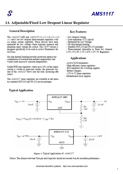
1A Adjustable/Fixed Low Dropout Linear Regulator- Low dropout voltage- Load regulation: 0.2% typical - Optimized for Low V oltage - On-chip thermal limiting- Standard SOT-223 and TO-252 packages- Three-terminal adjustable or fixed low dropout 1.2V ,1.5V ,1.8V , 2.5V , 2.85V , 3.3V , 5V . Regulators- Active SCSI terminators- High efficiency linear regulators- Post regulators for switching supplies - Battery chargers- 12V to 5V linear regulators - M otherboard clock suppliesThe AMS 1117-ADJ and AMS 1117-1.2,-1.5,-1.8,-2.5,-2.85, -3.3 and-5 are low dropout three-terminal regulators with 1A output current capability. These devices have been optimized for low voltage where transient response and minimum input voltage are critical. The 2.85V version is designed specifically to be used in Active Terminators for SCSI bus.On-chip thermal limiting provides protection against any combination of overload and ambient temperatures that would create excessive junction temperatures.Unlike PNP type regulators where up to 10% of the output current is wasted as quiescent current, the quiescent cur-rent of the AMS 1117 flows into the load, increasing effi-ciency.The AMS 1117 series regulators are available in the indus-try-standard SOT-223 and TO-252 power packages.Key FeaturesApplicationsGeneral DescriptionTypical ApplicationNotice: The distance between V out pin and Capacitor should not exceed 4cm for excellent performanceFigure 1. Typical Applications of AMS 11171A Adjustable/Fixed Low Dropout Linear RegulatorPin Assignments*With package soldered to 0.5 square inch copper area over backside ground plane or internal power plane, ΘJA can vary from 30°C/W to more than 50°C/W. Other mounting techniques may provide better thermal resistance than 30°C/W.Absolute Maximum RatingsFigure 2. Pin Assignments of AMS 1117ParameterMin.Max.UnitV IN 18 V(V IN – V OUT ) * I OUTSee Figure 3Operating Junction Temperature Range -20 125°C Storage Temperature Range-65150°C Lead Temperature (Soldering, 10 sec.) 300°C1A Adjustable/Fixed Low Dropout Linear RegulatorTypicals and limits appearing in normal type apply for T J =25℃.Limits appearing in Boldface type apply over the entire junction temperature for operation, -20℃to 125℃.Electrical CharacteristicBlock DiagramThermal LimitCurrent LimitV OUTV INSubstrateGND (fixed output) ADJ. (adjustable output)Figure 3. Block Diagram of AMS 1117SymbolParameterConditionsMin (Note 2) Typ (Note 1) Max(Note 2)UnitsV REFReference VoltageAMS 11171.5V<=(V IN -V OUT )<=7V,10mA<=I OUT <=1A1.225 1.250 1.275 VV OUT Output Voltage10mA<=I OUT <=1AI OUT = 10mA, V IN = 3.2V AMS 1117-1.2 ,2.7V<= V IN <=8.2V 1.176 1.152 1.200 1.200 1.224 1.248 V AMS 1117-1.5 ,3.0V<= V IN <=8.5V1.4701.5001.530VAMS 1117-1.8 ,3.3V<= V IN <=8.8V 1.764 1.800 1.836 VAMS 1117-2.5 ,4V<= V IN <= 9.5V 2.450 2.500 2.550 V AMS 1117-2.85 , 4.35V <= V IN <= 9.85V 2.793 2.850 2.907 V AMS 1117-3.3 , 4.8V<= V IN <=10.3V 3.234 3.300 3.366 V AMS 1117-5.0,6.5V<=V IN <= 12V4.9005.0005.100V1A Adjustable/Fixed Low Dropout Linear RegulatorTypicals and limits appearing in normal type apply for T J =25℃.Limits appearing in Boldface type apply over the entire junction temperature for operation, -20℃ to 125℃.Electrical Characteristic(Continued)Symbol ParameterConditionsMin (Note 2)Typ (Note 1) Max (Note 2) Units △V OUTLine Regultion (Note 3)I OUT =10mA ,(V OUT +1.5V)<=V IN <=12V 0.035 0.2 % Load Regultion (Note 3) V IN -V OUT =2V,10mA<= I OUT <=1A,0.2 0.7 % AMS 1117-1.2V IN -V OUT =2V,10mA<= I OUT <=1A,0.2 1 % V IN -V OUTDropout Volage I OUT =1A,△V REF =1% 1.100 1.250 V I LimitCurrent Limit V IN -V OUT = 2V, T J =25℃1.1 1.5A Minimum Load Current (Note 4) AMS 1117-ADJ1.5V<=(V IN -V OUT )<=10V10mA Quiescent CurentV IN =V OUT +1.25V 5 13 mA Thermal Regulation T A = 25°C, 30ms pulse 0.01 0.1 %/W RippleRejection f=120Hz,V IN -V OUT =3V, V Ripple =1V PP60 72 dB Adjust Pin Current50120µAAdjust Pin CurrentChange 1.5V<=V IN -V OUT <=7V, 10mA<=I OUT <=1A0.2 5 µATemperature Stability0.5 % Long Term StabilityT A = 125°C, 1000hrs.0.3%1A Adjustable/Fixed Low Dropout Linear RegulatorNote 1: Typical Values represent the most likely parametric norm. Note 2: All limits are guaranteed by testing or statistical analysis.Note 3: Load and line regulation are measured at constant junction room temperature. Note 4: The minimum output current required to maintain regulation.Typical Performance CharacteristicsTypicals and limits appearing in normal type apply for T J =25℃.Limits appearing in Boldface type apply over the entire junction temperature for operation, -20℃to 125℃.Electrical Characteristic(Continued)Symbol ParameterConditionsMin (Note 2) Typ (Note 1) Max (Note 2)UnitsI LimitRMS Output Noise(% ofV OUT )T A = 25°C, 10Hz<= f <=10kHz0.003 % Thermal Resistance, Junctionto CaseSOT-22315 ℃/W TO-252 3 ℃/W Thermal Shutdown Junction Temperature155 ℃ Thermal Shutdown Hysteresis25℃Output Current ( A )0 0.2 0.4 0.6 0.8 1.01.5 1.4 1.3 1.2 1.0 0.9 0.8 0.7 0.6 0.5 0D r o p o u t V o l t a g e ( V )Figure 4. Dropout Voltage VS. Output Current1A Adjustable/Fixed Low Dropout Linear RegulatorTypical Performance Characteristics(Continued)Figure 6. Output Voltage VS. TemperatureO u t p u t V o l t a g e ( V )3.70 3.65 3.603.553.50 3.45 3.40 3.35 3.30 3.253.20Junction Temperature ( ℃ )-75 –50 –25 0 25 50 75 100 125 150 175Figure 5. Reference Voltage VS. TemperatureR e f e r e n c e V o l t a g e ( V )0.260 1.255 1.250 1.245 1.240 1.235 1.225 1.220 1.215 1.210Junction Temperature ( ℃ )-75 –50 –25 0 25 50 75 100 125 150 175Figure 7. Minimum Load Current VS. TemperatureM i n i m u m L o a d C u r r e n t ( m A )5 4 3 2 1Junction Temperature ( ℃ ) -75 –50 –25 0 25 50 75 100 125 150 175Figure 8. ADJ Pin Current VS. TemperatureA D J P i n C u r r e n t ( µA ) 100 90 807060 50 40 30 20 10 0Junction Temperature ( ℃ ) -75 –50 –25 0 25 50 75 100 125 150 175Note:AMS 1117 OnlyAMS11171AAdjustable/Fixed Low Dropout Linear RegulatorMechanical Dimensions4-Lead SOT-223 PackageSymbolInches Millimeters NotesMin.Max.Min. Max.A Ñ .071 Ñ 1.80 A1 Ñ .181 Ñ 4.80B .025 .033 .064 .840 c Ñ 0.90 Ñ 2.29 D .248 .264 6.30 6.71 E .130 .148 3.30 3.71 e .115 .124 2.95 3.15 F .033 .041 .840 1.04 H .264 .287 6.71 7.29 I .0121 Ñ .310 Ñ J Ñ 10° Ñ 10° K 10° 16° 10° 16° L.0008 .0040 .0203 .1018 M 10° 16° 10° 16° N.010.014.250.360Figure 9. 4-Lead SOT-223 Package1A Adjustable/Fixed Low Dropout Linear RegulatorMechanical Dimensions(Continued)3-Lead TO-252 PackageNotes:1. Dimensions are exclusive of mold flash, metal burrsor interlead protrusion.2. Stand off-height is measured from lead tip with ref. toDatum –B-.3. Foot length is measured with ref. to Datum –A– withlead surface. 4. Thermal pad contour optional within dimension b3 and L3.5. Formed leads to be planar with respect to one anotherat seating place –C-.6. Dimensions and tolerances.SymbolInchesMillimetersNotesMin. Max.Min. Max.A .086 .094 2.19 2.39 b .025 .035 0.64 0.89 b2 .030 .045 0.76 1.14 b3 .205 .215 5.12 5.46 4 c .018 .024 0.46 0.61 c2 .018 .023 0.46 0.58 D .210 .245 5.33 6.22 1E .250 .265 6.35 6.73 1e .090 BSC 2.29 BSCH .370 .410 9.40 10.41 L .055 .070 1.40 1.78 3 L1 .108 REF 2.74 REFL3 .035 .080 0.89 2.03 4 L4.025.0400.641.02Figure 10. 3-Lead TO-252 Package1A Adjustable/Fixed Low Dropout Linear RegulatorAdvanced Monolithic Systems The " " logo is a registered trademark of Advanced Monolithic Systems.All other company and product names are trademarks of their respective ownersOrdering InformationPackageTemperature Range Part Number Output Voltage Packing Marking Transport MediaSOT -223-20℃ - +125℃ AMS 1117-1.2 1.2V AMS 1117 1.2 2.5K Tape and Reel -20℃ - +125℃ AMS 1117-1.5 1.5V AMS 1117 1.5 2.5K Tape and Reel -20℃ - +125℃ AMS 1117-1.8 1.8V AMS 1117 1.8 2.5K Tape and Reel-20℃ - +125℃ AMS 1117-2.5 2.5V AMS 1117 2.5 2.5K Tape and Reel -20℃ - +125℃ AMS 1117-2.85 2.85V AMS 1117 2.8 2.5K Tape and Reel -20℃ - +125℃ AMS 1117-3.3 3.3V AMS 1117 3.3 2.5K Tape and Reel -20℃ - +125℃ AMS 1117-5 5V AMS 1117 5 2.5K Tape and Reel -20℃ - +125℃ AMS 1117 Adjust AMS 1117 2.5K Tape and Reel TO -252-20℃ - +125℃ AMS 1117-1.2 1.2V AMS 1117 1.2 2.5K Tape and Reel -20℃ - +125℃ AMS 1117-1.5 1.5V AMS 1117 1.5 2.5K Tape and Reel -20℃ - +125℃ AMS 1117-1.8 1.8V AMS 1117 1.8 2.5K Tape and Reel-20℃ - +125℃ AMS 1117-2.5 2.5V AMS 1117 2.5 2.5K Tape and Reel -20℃ - +125℃ AMS 1117-2.85 2.85V AMS 1117 2.8 2.5K Tape and Reel -20℃ - +125℃ AMS 1117-3.3 3.3V AMS 1117 3.3 2.5K Tape and Reel -20℃ - +125℃ AMS 1117-5 5.0V AMS 1117 5 2.5K Tape and Reel -20℃ - +125℃ AMS 1117CD Adjust AMS 1117CD 2.5K Tape and ReelDisclaimer:• AMS reserves the right to make changes to the information herein for the improvement of the design and performancewithout further notice! Customers should obtain the latest relevant information before placing orders and should verify that such information is complete and current.• All semiconductor products malfunction or fail with some probability under special conditions. When using AMS productsin system design or complete machine manufacturing, it is the responsibility of the buyer to comply with the safety standards strictly and take essential measures to avoid situations in which a malfunction or failure of such AMS products could cause loss of body injury or damage to property.• AMS will supply the best possible product for customers!。
测试针英文规格书
测试针英文规格书Needle gauges are used to measure the thickness of a needle from its eye tothe tip of its point. The size of the needle is determined by the diameter of the round section of the needle. The gauge indicates the size of a needle in millimetres and is written as a number preceded by a point, e.g. 0.25mm is a25 gauge needle. The higher the gauge number the finer the needle.In medical and veterinary use, the size of needles that can be used depends on the size of syringe and the medication to be injected. In size, they rangefrom a thick 16 gauge needle used to inject medicines into animals to a very fine 30 gauge needle used to inject insulin in humans.In sewing, needles come in different lengths with different eye sizes andpoints to suit your type of stitching. The size of the needle is indicated bya number then the letter either NM for Metric needles or NE for English needles. An NM 80/12 needle is a fine needle for delicate fabrics such as chiffon and voile and an NM 16/100 would be a thicker needle for heavier fabrics.Sharp needles are often used in embroidery and tapestry work, in this case the needles come in various lengths and thickness. The needle gauge is a handytool for measuring the diameter of the needle to ensure that the needle is the correct size for the intended purpose.Many people use a needle gauge to measure how thick their thread is. To do this, they lay the thread over the grooves and notches on the gauge and seethe notch that the thread lies in and read the corresponding millimetre size. The thread size should match or be slightly thicker than the needle size.A typical needle gauge is a round disc made of stainless steel with a range of notches and grooves along its circumference. As the needle gauge is round, it can measure large or small needles as it can rotate to access the needle's tip.Needle gauges are a convenient and accurate way of measuring the thickness of needles and thread and ensuring the correct needle is chosen for the job athand. They are useful both within the medical and the sewing community, as well as others who may require the use of needles and thread, such as leatherworkers, beaders and jewellers. Investing in a needle gauge is an important and useful tool for both domestic and commercial use.。
英语书信作文的格式

英语书信作文的格式Title: Format for Writing an English Letter。
Writing a letter in English requires adherence to a specific format to ensure clarity and professionalism. Below, I outline the standard format for writing an English letter:### 1. Sender's Address:[Your Name] 。
[Your Address Line 1] 。
[Your Address Line 2 (if applicable)] 。
[City, State/Province, Zip/Postal Code] 。
[Country (if applicable)]### 2. Date:[Month Day, Year]### 3. Recipient's Address:[Recipient's Name] 。
[Recipient's Title (if applicable)] 。
[Company/Organization Name (if applicable)] 。
[Recipient's Address Line 1] 。
[Recipient's Address Line 2 (if applicable)] 。
[City, State/Province, Zip/Postal Code] 。
[Country (if applicable)]### 4. Salutation:Dear [Recipient's Name],。
### 5. Body of the Letter:Introduction: Begin with a polite greeting and introduce yourself if necessary.Main Content: Clearly state the purpose of your letter. Use paragraphs to organize your thoughts logically.Closing Remarks: Conclude the letter with any additional information or requests. Express gratitude if appropriate.Closing: Use a closing phrase such as "Sincerely," "Yours faithfully," or "Best regards," followed by your name.### 6. Signature:[Your Signature (if sending a physical letter)]### Example:```。
