如何根据WinCC设置S7控制器的时间
wincc怎么往PLC中写入时间?

wincc怎么往PLC中写入时间?
wincc怎么往PLC中写入时间?我想从WINCC中往300PLC的定时器写时间,但是问题是,直接写得话,单位是MS,就算是在WINCC中对模拟变量做线性标定,那也不行,因为我要写得时间范围是1小时到2个半小时,在以毫秒为单位的情况下,线性标定也达不到那么长得时间,请问还有什么方法吗?
问题补充:
你在PLC里对时间进行转换处理就可以了。
这个方法好啊,但是能不能说具体点
最佳答案
从上位机写整型数INT或实数REAL到PLC,首先该数值需包含以毫秒为单位的时间值,在写入PLC的数据存储区后,利用ITD(IntegertoDoubleInteger)或RND (RealtoDoubleIntegerwithRoundingOff)将该值转换为双整形,然后将该值写到类型为TIME的变量里,在程序中调用FC40,将TIME转换成S5TIME即可。
由HMI输入秒数,在PLC中进行换算:
秒数*1000>>得到毫秒数>>FC40(TIM_S5TI)>>转换得到正确地S5TIME
参考链接:
/download/Upload/AS/applicati on/A0335.pdf
《如何根据WinCC设置S7控制器的时间?》
/CN/view/zh/7802886
参考资料:/service/answer/solution.aspx?Q_ ID=33793&cid=1029。
【案例】S7-200SMART实时时间如何在触摸屏上显示并写入

【案例】S7-200SMART实时时间如何在触摸屏上显示并写入蓝字"技成PLC课堂”关注我们哦!今天为大家带来如何在威纶通触摸屏上显示S7-200SMART PLC 实时时间,有些时候,我们想在触摸屏显示PLC实时时间,还有监控PLC很麻烦,接下来就带大家不用监控PLC直观的在触摸屏上去显示实时时间。
一、读实时时钟时间第一步:(在桌面打开STEP 7-MicroWIN SMART编程软件)第二步:(用字节转整数+BCD码转整数指令来读取实时时钟时间【B_I—BCD_I】)第三步:(读取实时时钟指令【READ_RTC】)二、写时钟时间第一步:(用整数转BCD码+整数转字节来写入时钟设定时间【BCD_I—I_B】)第二步:(设置实时时钟指令【SET_RTC】)第三步:(监控读取PLC实时时间,当时时间:2020年6月11日15:09星期四)第四步:(监控写入PLC设定时间,设定时间: 2016年6月12日18:22分星期日)注意事项:在最后第八位表示星期的时候其中1 = 星期日,7 = 星期六,0 = 表示禁止计星期。
三、组态触摸屏显示时间第一步:(在桌面上打开Utility Manager组态软件)第二步:(创建一个读取时间画面)1. 通过鼠标选中数字右击来新增基本画面并把窗口名称重新命名(读取时间)2. 设置数显、关联地址、设置标签文字、设置功能键切换窗口。
第三步:(创建一个写入时间画面)1. 通过鼠标选中数字右击来新增基本画面并把窗口名称重新命名(写入时间)2. 设置数显、关联地址、设置标签文字、设置功能键切换窗口。
四、在线模拟看一下第一步:(点击启动读取按钮,现在读取PLC时间是:2020年10月12日星期一 10:01 04秒)第二步:(先写入一个日期和时间,然后点击启动写入按钮,切换到读取时间窗口这时会看到时间已经写入成功并计时开始)(来源:技成徐成爽,未经允许不得转载,违者必究!)。
如何同步操作面板与 S7-200300400 控制器的日期和时间
1.操作面板同S7-200 CPU间的时钟操作1.1使用S7-200 CPU时钟对操作面板的时钟同步步骤如下:(1) 在Micro/Win中,周期调用READ_RTC函数,以定时读取S7-200 CPU的系统时钟,将时钟信息存放在V区,比如VB100。
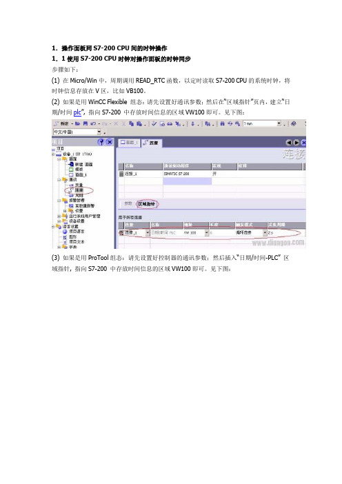
(2) 如果是用WinCC Flexible 组态:请先设置好通讯参数;然后在“区域指针”页内,建立“日期/时间plc”, 指向S7-200 中存放时间信息的区域VW100即可。
见下图:(3) 如果是用ProTool组态:请先设置好控制器的通讯参数;然后插入“日期/时间-PLC” 区域指针, 指向S7-200 中存放时间信息的区域VW100即可。
见下图:1. 2通过面板修改S7-200 PLC时钟大致设置如下:(1) 在操作面板项目中创建: 1个标志变量(比如:地址为V20.0)和年、月、日、时、分、秒6 个BYTE变量,分别连接到PLC的连续V区中,比如:VB70 – VB75。
(2) 在MicroWin中,用标志变量触发来调用SET_RTC,将VB70 – VB75作为时间参数传递给该函数,来实现通过面板修改S7 PLC时间。
(3) 注意:给S7-200设定系统时间时,不要给时间信息中的“星期”字节赋“0”值,请给出确切的“星期几”否则会导致时钟同步失败。
或将此字节置为常数1。
本章详细设置参考例程如下: ( 1247 KB )2.操作面板同S7-300/400 CPU间的时钟操作2.1 使用S7-300/400 CPU时钟对操作面板的时钟同步步骤如下:(1) 在Step7中:新建DB块DB1,在DB1中按顺序定义两个变量:MyTimeDate 类型为DATE_AND_TIMEtemp 类型为DWORD周期调用SFC1(READ_CLK)函数(可以在OB35中调用),以定时读取S7-300 CPU的系统时钟,将时钟信息存放在变量DB1. MyTimeDate中。
wincc时间的问题_1

wincc时间的问题
在做WINCC历史数据及曲线的控件时,数据的时间都是根据操作系统的时间,而操作系统的时间又可以随便调整,严格的讲,这些数据对应的时间存在很大的风险,比如操作人员随意更改了系统时间,WINCC存取的数据时间就不正确了,有什么办法可以很好的处理呢。
最佳答案
1、对于服务器/客户机结构,将WinCC时基设置为服务器时间,再做好服务器时间的校准和Windows操作权限设置工作即可;
2、对于单站结构,归档数据各自为政,无法共享,做好单站时间的校准和Windows操作权限设置工作即可;
3、规范的话,可以将AS时间设置为主时钟源,为网络上其他设备授时,或者设置单独的GPS或NTP服务器作为主时钟源。
再做好各Windows系统的操作权限设置工作即可。
wincc时间格式的更改
时间显示的格式是在WinCC在线趋势控制中通过“控制面板>区域和语言设置>区域选项>自定义>时间”设置的。
在此可指定想使用12还是24小时的显示格式。
如果设置被更改,系统必须重新启动才能使更改生效。
1.利用Wincc本身的时间控件,就是那个不能变24小时制的。
在打开画面中做一C动作。
代码如下:SetPropChar(lpszPictureName,"控件1","LocaleID","2052");问题解决。
对于时间控件显示时间的一点补充在第一种方法里,在打开画面里赋了C动作之后,在画面一打开的时候时间控件就有个框,非得在其他地方点一下才可以,问我怎么解决。
我刚看了一下,出现那个虚线框的原因是因为在对控件N赋值之后,控件自然就成为了画面的焦点。
我看了一下,在控件的属性里,有一项叫“FocusRect”,把这个取消就可以了。
2.在全局脚本中做一动作。
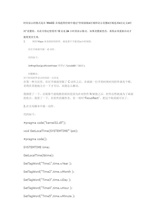
代码如下:#pragma code("kernel32.dll");void GetLocalTime(SYSTEMTIME* lpst);#pragma code();SYSTEMTIME time;GetLocalTime(&time);SetTagWord("Time1",time.wYear );SetTagWord("Time2",time.wMonth );SetTagWord("Time3",time.wDay );SetTagWord("Time4",time.wHour );SetTagWord("Time5",time.wMinute );SetTagWord("Time6",time.wSecond );SetTagWord("Time7",time.wDayOfWeek );其中Time1~Time7为所建立的变量,我建立的是16位有符号数,在画面上做几个输入输出域连上即可。
WinCC显示和更改PLC中的时间变量

return FALSE; } hProp = RPJCreatePropertyHandle( g_szProj, pError ); if( !hProp ) {
printf( "Error RPJCreatePropertyHandle(...) " );
return FALSE;
}
if( !RPJSetJobProps( hProp, jobname, pError ) )
{
printf( "Error RPJSetJobProps(...)
" );
RPJDeletePropertyHandle( hProp, pError );
return FALSE;
}
(VARTYPE)typ,
if( !RPJSetProperty( hProp, propname1, ptr1,
200, pError ) )
{
printf( "Error RPJSetProperty(...)
" );
RPJDeletePropertyHandle( hProp, pError );
2. 取消时间范围的选择,并建立好变量选择,这里的变量应该是变 量记录中的归档变量,其采集时间是从归档变量中设置的。
3. 完成后退出并新建打印作业。取消启动参数的选择,选择时间范 围中的绝对时间。
4. 实现打印功能最关键的是一个新建的项目函数,西门子的教程上 有例子。我已将条是调试通过。
/*********************************************************************** ******/
wincc flexible 中如何设定日期和时间?并且断电不消失
wincc flexible 中如何设定日期和时间?并
且断电不消失
winccflexible中如何设定日期和时间?并且断电不消失啊?‘
最佳答案
首先HMI作用是读取和写入数据组态值的设备。
它本身就没有这个功能,需要通过PLC进行的。
断电记忆功能需要在PLC中进行,如果是200可以通过添加电池卡或者设置数据保持地址范围进行,300的话直接采用数据块地址编程(数据块默认值是断电保持型的)。
200PLC的读取和写入系统时钟指令为:READ_RTC/SET_RTC
300plc的读取和写入系统时钟指令为:SFC0、SFC1
以上读取和写入时钟的地址存储形式都以字节形式进行的。
在HMI设备上组态若干个I/O域,赋值与PLC的读取和写入地址一致的地址和写入时钟的按钮。
S7-400PLC系统时间设置方法及在炼钢厂中的应用
【 关键词 】P L C S t e p 7数据类型 系统时间
西 门子公 司 自控系 统在 武钢 集 团 昆钢 第 三 炼钢 厂 中 应用 非常 广 泛 ,例 如 4 撑转 炉、
3 # L F精 炼 炉 等 过 程 系 统 。 西 门 子 s 7 . 4 0 0 P L C
系统具有可靠性 高、抗干扰 能力强、适用性强 等特点 ,而且软件 易学易用 ,接 口容易,编程
电子技术 ・ E l e c t r o n i c T e c h n o l o g y
S 7 — 4 0 0 P L C系统时 间设置方法及在炼钢厂 中的应 用
文/ 景 志 峰 刘 宁 雁 。
—●t●蜘
1 :Tit le:
主要 介绍 西门子 S 7 — 4 0 0 P L C 硬 件 系统 中 ,利 用 S t e p 7编 程 软 件 进行 对 P L C硬 件 系统 进 行 时 间 设 定 的 方 法 , 以 及 用 编 程 软 件 读 取 系统 时 间 的 方 法 通 过 这 种 方 法 的 运 用 , 成 功地 运 用 于 武 钢 集 团 昆钢 第 三 炼 钢 厂 能 耗 累 计 、 产 量 统 计 等 工作 。
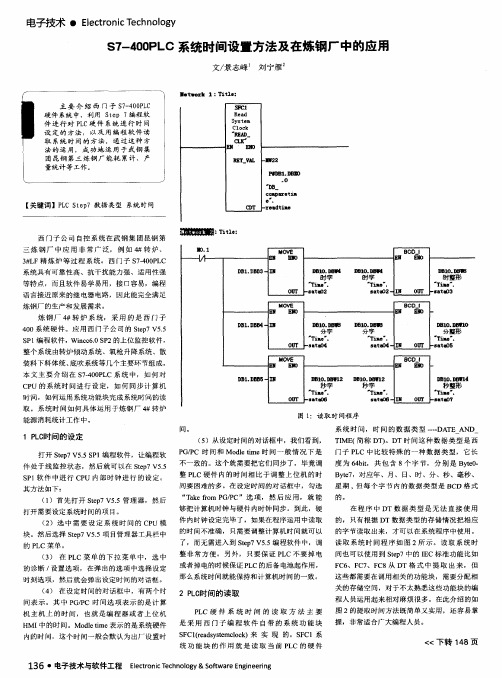
整个系统 由转 炉倾动系统、氧枪升 降系统 、散 装料下料体统 、 底吹系统等几个主要环节组成 。 本 文主 要介 绍 在 s 7 — 4 0 0 P L C系 统 中,如 何对 C P U的系 统时 间进 行设 定,如 何 同步计 算机 时 间,如 何运 用系统功能块完成系统时 间的读 取 。系 统时 间如何 具体运用 于炼钢 厂 4 转炉
其方法如 下:
T I ME ( 简称 D T ) 。DT时 间这种 数据类 型是 西 门子 P L C 中比较特 殊 的一 种数 据类 型,它 长 度为 6 4 b i t ,共包 含 8个字 节, 分别 是 B y t e 0 .
wincc 怎样实现数字时钟?

wincc 怎样实现数字时钟?怎样实现wincc软件gps授时。
就是,plc控制站及操作站wincc,接受gps的时间?plc通过winccc传受。
最佳答案1、首先通过你的计算机或plc建立与gps接收机联系,其后应用wincc来读取这个时间数据。
有关gps接收器提供了详细的说明及如何装配和配置gps接收,详见:/information/manage/edit/uploadfile/gi s/ch26.pdf2、wincc如何获取系统时间:wincc通道“systeminfo”:从winccv5.0sp2开始,wincc就提供了通道“systeminfo”,通过该选项就可以建立一个wincc文本变量来获取系统时间。
该wincc变量可以用于在过程画面中显示本地计算机的系统时间,或者在全局脚本中利用该变量。
但是不可以通过它来进行时间设置3、相关文档:详见连接:/cn/llisapi.dll?func=cslib. csinfo&objid=24202491&nodeid0=10805585&caller=view&lan g=zh&siteid=cseus&aktprim=0&objaction=csopen&extranet=st andard&viewreg=cn参见《如何同步操作面板与s7-200/300/400控制器间的日期和时间》的例子:/cn/llisapi.dll?func=cslib. csinfo&objid=34281179&load=treecontent&lang=zh&siteid=cs eus&aktprim=0&objaction=csview&extranet=standard&viewre g=cn。
plc时间同步
关于该用法的详尽信息可参看 WinCC 在线帮助:“ WinCC 信息系统 > 使用 WinCC > 创建过程画面 > 使用控件 > WinCC 数字/模拟时钟控件”。
注意:
该控件无法为其它应用(例如全局脚本)提供时间值或者通过其设置(改变)时间值。
可以在 Windows 提示符窗口中输入“help time”或者“help date”可以看到这两个命令的简要描述。
可以在 WinCC 的脚本 ( C 或者 VB 脚本 ) 中使用以上提及的命令提示符命令。下面提供了 C 及 VB 脚本样例程序:
Global Script C
ProgramExecute("cmd /c time 14:16");
注意:
本地计算机时间是字符串类型的。通过 WinCC 变量读出后,可以编辑该字符串,可以将其拆分(例如年,月,日,时,分秒)。应该注意的是该时间显示的格式与操作系统的区域设置相一致。
(3) Windows API 函数
可以在 C 全局脚本中调用 Windows API 函数:
GetLocalTime(),
or
system("time 14:16");
VBScript
Dim objWshShell
Set objWshShell = CreateObject("Wscript.Shell")
objWshShell.Run "cmd /C time 14:16", 1
void GetLocalTime(SYSTEMTIME *lpst);
在WinCC项目中监控S7PLC中定时器及计数器

如何在WinCC项目中监控S7 300/400 PLC中的定时器及计数器 How to Monitor and Control the TIMER and COUNTER of S7 300/400 PLC in WinCCProject摘要 本文详细描述了如何利用WinCC的类型转换功能来实现在WinCC项目中监控S7300/400 PLC中的TIME,S5TIME数据类型变量及定时器和计数器的值。
关键词WinCC, 类型转换 , TIME, S5TIME, 定时器,计数器Key Words WinCC, Type Conversion, TIME, S5TIME, TIMER, COUNTERIA&DT Service & Support Page 2-17目录1.在WinCC项目中监控S7 300/400 PLC中的TIME类型变量 (4)1.1关于TIME数据类型 (4)1.2具体步骤 (5)2. 在WinCC项目中监控300/400PLC中的S5TIME类型变量 (8)2.1 关于S5TIME数据类型 (8)2.2 具体步骤 (9)2.3定时器的监控 (12)3.在WinCC项目中监控S7 300/400 PLC中的计数器值 (13)3.1 关于计数器 (13)3.2 具体步骤 (13)IA&DT Service & Support Page 3-17WinCC中变量的数据类型可能会不同于自动化系统中所使用的数据类型。
因此,当组态外部变量时,除了要定义该变量的数据类型,还必须对所有数字型数据类型执行类型转换。
类型转换定义如何从WinCC格式转换到AS格式,该定义适用于双向传送。
下表显示哪些WinCC数据类型支持类型转换:数据类型 类型转换二进制变量 否无符号8位数 是有符号8位数 是无符号16位数 是有符号16位数 是无符号32位数 是有符号32位数 是浮点数32位IEEE 754 是浮点数64位IEEE 754 是文本变量8位字符集 否文本变量16位字符集 否原始数据类型 否有关类型转换的详细信息,您可在WinCC信息系统中的“通讯”>“过程通讯”>“WinCC过程通讯”>“外部变量”中找到。
在PCS7中如何设置时间同步和声音报警

一:时间同步需要许多参数的设置,具体设置如下:
1) 在系统的硬件组台中点击CPU 属性,“诊断/时钟”下将“时钟”的选项设为“在
PLC 中” 设为“作为从站”。
其它的选择默认。
如下图:
2) 在系统的硬件组台中点击CP443-1属性,将“时钟同步”中的“SIMATIC 模式”
的“激活SIMA TIC
3) CP1613 网卡的设置:将CP1613的“时钟同步”选为“已激活”就可以了。
如下
图:
“开始”——“ SIMATIC ”——“SIMATIC NET ”——“Configuration console ” ——“常规”。
设置CP1613网卡的时候,需要先把CP1613网卡的模式选为“PG ”模式。
修改后必须改回“组态模式”。
作为从站
已激活
4)WINCC中设置:
打开WINCC,点击“时间同步”,设置为下图所示。
5)在工程师站上时间的设置:点击电脑右下角的时间。
将时区选为“GMT”,并且取消“根据夏时制自动调节时钟”。
如下图:
再将“Internet时间”取消“自动与Internet时间服务器同步”,如下图:
注:在WINCC运行期间,不允许修改电脑的时间(就是电脑右下角的时间),一旦修改,WINCC上就会有报警,同时WINCC的“同步时钟”将自动改为“取消时间同步”(我们设置的是“允许时间同步”)。
二:声音报警:
在WINCC中点击“报警器”主要参考以下的设置:
其中“消息类别”选择为“PLC过程系统消息”,“授权”要根据自己的设定需要。
其中变量是内部二进制变量:如下图:
最后一项选择报警时发出的声音,格式为.W A V。
1、如何在wincc中输入时间传送s71500

有时候我们需要在wincc画面中输入时间值,传送给PLC。
以下就是wincc7.2中输入开始时间和结束时间做定时用,传送给PLC s7-1500,经过变换,PLC输出一个定时状态。
1、在wincc中变量管理-结构变量中新建结构类型(类型名为:时间输入)。
结构类型包含两个元素:时和分。
都为无符号的32位值,外部变量。
2、在新建的结构类型“时间输入”下建两个变量,分别为“JS_T_输入”和“KS_T_输入”作为定时结束时间和定时开始时间,数据类型默认为“时间输入”选择连接到的位置,我的是之前建好的连接1500,选择地址,我的如下表。
地址一定要按照字节长度排好。
3、在WINCC画面中做输入输出域,我的例子共4个,开始时间的“时”,开始时间的“分”,结束时间的“时”,结束时间的“分”。
做好4个输入输出域的数据连接,输入输出域的属性。
“时”-上限值位23,下限值为0,数据格式10进制,输出格式99。
“分”-上限值59,下限值为0,数据格式10进制,输出格式为99。
以上的操作是wincc部分的操作,接下来需要做PLC的操作了。
4、首先在s7-1500编程软件中新建变量。
地址要与我们在wincc中建立的变量吻合。
5、接下来新建一功能,编写程序。
以下是我的程序。
思路如下:在S7-1500中数据格式TIME_OF_DAY(时间),占用4个字节,例如10小时11分58秒312毫秒的表示格式为:TOD#10:11:58.312,按照时分:秒.毫秒排序。
在规定的取值范围内,Time_OF_DAY类型数据可以与DINT类型的数据相互转换(TOD#00:00:00.000对应0),DINT数据每增加1,时间增加1ms。
我们在程序中输入的时,换算成ms,则应该乘以3600000;输入的分,换算成ms,则应该乘以60000。
输入时与分相加,则为总的输入时间。
程序中,我们使用RD_LOC_T读取系统时间DATE_AND_TIME,然后用T_CONV将时间转换为TIME_OF_DAY格式。
如何根据WinCC设置S7控制器的时间

仅当C脚本在WinCC中被调用时,时间才被设置。SFC0必须先添加到Step7程序的块文件夹中。
用"SET_CLK"设置完时钟后,触发变量被复位。
在此段程序中,本地变量"DateAndTime"存储在以0为起始地址的本地数据堆栈中。如果不得已要把这个变量分配到别的地址,同时对传送指令参数化时,必须要考虑到地址分配的问题。(见图2)。
更多信息:
时钟同步的设置参考条目ID:16622902.
如何通过以太网组态时钟同步参考条目钟同步参考条目ID:11932931.
说明:
步骤.
过程
1
创建一个数据块(在本例中是DB1),其中有一个"DATE_AND_TIME"类型的变量和一个"Byte"类型变量。
图01:创建DB1
2
按照给定的顺序在FB的临时/本地区域中创建下列变量。
1.时戳TimeStamp定义为"Date_And_Time"类型
2.返回值ret_value定义为"Int"类型
3
在FB中创建一个新的network,并拷贝下面.txt文件中的STL代码到这个network中:
AWL-Code.txt( 786 bytes )
如何根据WinCC设置S7控制器的时间?
描述:
下面的方法只能进行时间设置而不能完成时间同步的功能。因为必须考虑到延迟,比如报文的处理时间,C脚本的运行时间等,因此这个方法在精度方面不如真正的时间同步精确。
还要注意时间跳变(向前/向后)的发生,这就意味着这个方法不适用于必须按时间正向顺序的应用。
The following solution writes the time (type DATE_AND_TIME) with a WinCC script into a global data block (DB) of the controller下面的方法是使用WinCC的脚本把时间(DATE_AND_TIME类型)写到PLC的全局数据块(DB)中。在function block (FB)中,时间从DB中读出并写到临时/本地变量(时戳)中。该变量在系统功能块"Set_Clock"调用时被传送,从而设置到PLC中。
S7-400 CPUs与WinCC的时间顺序消息配置指南说明书

Configuring chronological messagingEntry ID: 23730697C o p y r i g h t S i e m e n s A G 2008 A l l r i g h t s r e s e r v e d 23730697_W i n C C _Z e i t f o l g e R i c h t i g M e l d e n S 7400_e .d o cContentsContents ..............................................................................................................2 Question (2)How do you implement chronological messaging with S7-400 CPUs and WinCC? (2)Answer (2)Follow the action commands and notes listed in this document for a detailed answer to the above question (2)1 Information ...........................................................................................3 1.1 Instructions...........................................................................................3 1.2 Message classes..................................................................................3 1.3 Message types.....................................................................................3 1.4 OS project editor ..................................................................................4 1.5 Block attribute alarm_ui........................................................................4 1.6Additional information...........................................................................5 2 Configuration........................................................................................6 2.1 Configuring symbol-related messages.................................................6 2.1.1 Configure extended attributes for messaging in the symbol table.......6 2.1.2 Download program in PLC...................................................................8 2.1.3 Compile the OS....................................................................................8 2.1.4 Download the OS...............................................................................10 2.1.5 Test the messages at WinCC Runtime..............................................11 2.2 Configuring block-related messages..................................................11 2.2.1 Copy SFC35 (ALARM_8P) into current project .................................11 2.2.2 Create a message-compatible block..................................................12 2.2.3 Connect the parameters of the system message block with thecorresponding inputs/outputs of the function block............................13 2.2.4 Configure standard messages...........................................................14 2.2.5 Call message-compatible block in the program.................................15 2.2.6 Configure block-related messages.....................................................16 2.2.7 Download PLC, Compile OS and Download OS ...............................18 2.2.8 Test the messages at WinCC Runtime..............................................18 3 History (19)This entry originates from the Internet site of Siemens AG, Automation and Drives, Service & Support. Go to the following link to download this document. /WW/view/de/23730697QuestionHow do you implement chronological messaging with S7-400 CPUs and WinCC?AnswerFollow the action commands and notes listed in this document for a detailed answer to the above question.Entry ID: 23730697C o p y r i g h t © S i e m e n s A G 2008 A l l r i g h t s r e s e r v e d 23730697_W i n C C _Z e i t f o l g e R i c h t i g M e l d e n S 7400_e .d o c1Information1.1InstructionsThis entry shows you how to implement chronological messaging with an S7-400 CPU and WinCC. Chronological messaging means that the messages are sent from the PLC to the WinCC station. When they are created in the PLC, themessages are given a time stamp and then sent to the WinCC station. The WinCC station does not poll the PLC, which significantly reduces the bus load. There are basically two types of message in STEP 7:1. Symbol-related messagesSymbol-related messages can only be generated by CPUs of the S7-400 series. The messages are triggered asynchronously to the program. 2. Block-related messagesBlock-related messages can be generated by CPUs of the S7-300 and S7-400 series.The block-related messages are created by the STEP 7 program using the system message blocks (e.g. ALARM_8P). The message is sent as soon as the STEP 7 program calls a system message block and the conditions forsending a message are fulfilled. The messages are triggered synchronously to the program.1.2Message classesMessages are sorted into message classes according to their usage (e.g. Alarm, Warning). You can configure 16 message classes.1.3 Message typesThe message types divide the message classes once again (e.g. Alarm High for High Limit Exceeded, Alarm Low for Low Limit Exceeded). You can configure 16 message types per message class.NoteThe message types are numbered consecutively, i.e.:∙ Message class 1 has message types 1-16 ∙ Message class 2 has message types 17-32 ∙Message class 16 has message types 241-256The texts of message classes and message types are not compiled to WinCC, only the message class and message type numbers are used to assign the messages in WinCC to a message class and message type respectively.WARNINGThe message class and message type numbers used in STEP 7 must also be configured in WinCC. If a message is triggered in STEP7 with amessage class number or message type number, for which no message class or message type number is configured in WinCC, then this is marked purple in Alarm Logging and no message is displayed in the Runtime.Entry ID: 23730697C o p y r i g h t © S i e m e n s A G 2008 A l l r i g h t s r e s e r v e d 23730697_W i n C C _Z e i t f o l g e R i c h t i g M e l d e n S 7400_e .d o c1.4 OS project editorIf you are using the OS project editor, the message classes and message types that are available to you for configuring messages are created automatically. It is not necessary to configure the messages in WinCC.If you do not use the OS project editor, you must configure the message classes and message types in WinCC. For which STEP 7 message class is assigned to which message class and message type in WinCC, please refer to Entry ID: 31622970.1.5 Block attribute alarm_uiIf this block attribute is set to "True", the PCS 7 message configuration dialog is available. In this dialog, the following texts are added automatically to the messages and do not have to be configured.∙ Origin ∙ Area∙ Charge Name ∙ OperationIf this block attribute is set to "False", the message text and 9 additional texts are available for each message when configuring messages. These texts are assigned to the corresponding user text blocks in WinCC. Instructions for configuring the additional texts and the assignment of the additional texts are available in Entry ID: 30550239.Entry ID: 23730697C o p y r i g h t © S i e m e n s A G 2008 A l l r i g h t s r e s e r v e d 23730697_W i n C C _Z e i t f o l g e R i c h t i g M e l d e n S 7400_e .d o c1.6 Additional information∙Reference manual "Programmable Logic Controller S7-400 CPU Data" This gives you detailed information on the available message procedures of a CPU. This documentation is part of the documentation package 6ES7498-8AA03-8AA0. The manual is available for downloading in Entry ID: 19538001. ∙Manual "Operation List S7-400 CPU 412, 414, 416, 417"This gives you detailed information on available system functions and system function blocks for creating CPU messages. This documentation is part of the documentation package 6ES7498-8AA04-8AN0. The manual is available for downloading in Entry ID: 1117645.∙STEP 7 Online HelpYou can find detailed information about alarm processes, alarm types and system alarm blocks in the STEP 7 Online Help.Entry ID: 237306972 ConfigurationRequirements∙The WinCC component "AS-OS Engineering" is installed.You can select this component when doing a user-defined setup of WinCC. Please use the following installation sequence:3. STEP 74. WinCC with the "AS-OS Engineering" componentEntry ID: 22272911 includes a description of how to retro-install the "AS-OS Engineering" component. ∙The WinCC project is integrated in the STEP 7 project.Entry ID: 11841504 contains information on how to integrate a WinCC project in STEP 7.∙The "Alarm Logging Runtime" is enabled in the startup list in the "Computer Properties" dialog of the WinCC project.Below we show you how to configure symbol-related and block-related messages.C o p y r i g h t © S i e m e n s A G 2008 A l l r i g h t s r e s e r v e d 23730697_W i n C C _Z e i t f o l g e R i c h t i g M e l d e n S 7400_e .d o c2.1Configuring symbol-related messages2.1.1Configure extended attributes for messaging in the symbol table1. In SIMATIC Manager, open the symbol table.2. Using the menu command "View > Columns R, O, M, C, CC Ctrl+K" you makeadditional properties to the symbols used visible. 3. Create a symbol (e.g. "PUMP1_Message0") that is to trigger a message.Assign an address, e.g. "M100.0" (BOOL data type).Figure 2-1Entry ID: 237306974. Assign the attribute "M" for messaging for the symbol that is to trigger amessage. For this you open the "Message Configuration" dialog by clicking on the relevant option field in the "M" column. You can also open the "Message Configuration" dialog via the pop-up menu "Special Object Properties > Message...".C o p y r i g h t S i e m e n s A G 2008 A l l r i g h t s r e s e r v e d 23730697_W i n C C _Z e i t f o l g e R i c h t i g M e l d e n S 7400_e .d o cFigure 2-25. Make the settings in the "Message Configuration" dialog.Figure 2-3Entry ID: 237306976. Here you can parameterize the message and information texts, the messageclass and other properties of the message. With the "More>>" button you can parameterize more parameters (e.g. Additional text, SCAN attributes etc.).C o p y r i g h t S i e m e n s A G 2008 A l l r i g h t s r e s e r v e d 23730697_W i n C C _Z e i t f o l g e R i c h t i g M e l d e n S 7400_e .d o cFigure 2-47. Click the "OK" button to acknowledge the message configuration. 8. Repeat the message configuration for all the symbols that are to generatemessages. 9. Save the symbol table, for example, using the menu command "Symbol Table> Save". When you save the symbol table, a system data block ("SDB 305") is created.NoteIt is also possible to configure the message texts in multiple languages. The display language currently selected is shown in the "Message Configuration" dialog. You configure the message texts for all those languages that will be used later for WinCC Runtime. For this you change the standard language in the SIMATIC Manager with the menu command "Options > Language for Display Devices" and repeat message configuration for each language separately. The attribute in the "O" column (operator control and monitoring) determines whether the symbol is created as a WinCC tag when compiling is performed.2.1.2 Download program in PLCDownload the S7 program into the PLC.2.1.3 Compile the OS"OS Compile" creates the messages in WinCC. In earlier versions the procedure was also done with "Mapping" or "Transfer PLC/OS Connection Data".Entry ID: 23730697RequirementsThe PLC's CPU and the OS must be networked. There must be at least one common network connection in NetPro.Figure 2-5C o p y r i g h t S i e m e n s A G 2008 A l l r i g h t s r e s e r v e d 23730697_W i n C C _Z e i t f o l g e R i c h t i g M e l d e n S 7400_e .d o cEntry ID: 237306971. Start the OS compilation procedure. In the SIMATIC Manager you select theOS and then in the associated pop-up menu you select "Compile".Figure 2-6C o p y r i g h t S i e m e n s A G 2008 A l l r i g h t s r e s e r v e d 23730697_W i n C C _Z e i t f o l g e R i c h t i g M e l d e n S 7400_e .d o cA wizard takes you through multiple dialogs. Here you can make various settings for compiling the OS. You must select which PLC program is assigned to which OS and which connection is to be used.NoteUsing the "Back" and "Next" buttons you can navigate in the wizard's settings mask. With the "Finish" button you get a summary of the compilation procedure displayed.2. Start the compilation procedure with the "Compile" button.2.1.4 Download the OSDownload the program into the OS.Entry ID: 23730697C o p y r i g h t S i e m e n s A G 2008 A l l r i g h t s r e s e r v e d 23730697_W i n C C _Z e i t f o l g e R i c h t i g M e l d e n S 7400_e .d o c2.1.5 Test the messages at WinCC RuntimeStart WinCC flexible Runtime. Trigger the messages using the variable table. The messages are displayed in the alarm window of WinCC and can be acknowledged where necessary.Figure 2-72.2 Configuring block-related messagesHere we present block-related messaging using the system message block SFB35 (ALARM_8P). The procedure using the other system message blocks is essentially identical.2.2.1 Copy SFC35 (ALARM_8P) into current project1. In the SIMATIC Manager you select "File > Open... > Libraries" and open theStandard Library. 2. Select the system message block SFB35 (ALARM_8P). It is located in thedirectory "Standard Library > System Function Blocks > Blocks". 3. Copy the system message block SFB35 into the project.Entry ID: 237306972.2.2 Create a message-compatible block1. Insert a new function block, e.g. "FB1" into the STEP 7 project. The languageused is STL. 2. Open the function block "FB1". 3. Create the following input variables:Table 2-1NameDatentypeEV_ID DWORDSIG1 ... SIG8 BOOL SD1 ... SD10REAL4. Create the following output variables:Table 2-2C o p y r i g h t S i e m e n s A G 2008 A l l r i g h t s r e s e r v e d 23730697_W i n C C _Z e i t f o l g e R i c h t i g M e l d e n S 7400_e .d o cName DatentypDONE BOOL ERROR BOOLSTATUS WORD ACK_STATE WORD5. Create the following instance FB variable in the static area:–ALARM (ALARM_8P or SFB35)6. Open the "Object Properties" dialog of input "EV_ID". Assign the followingattributes:– S7_a_type = alarm_8p – S7_server = alarm_archivFigure 2-87. Select the system message block SFB35 (ALARM_8P) in the program part.Entry ID: 23730697C o p y r i g h t S i e m e n s A G 2008 A l l r i g h t s r e s e r v e d 23730697_W i n C C _Z e i t f o l g e R i c h t i g M e l d e n S 7400_e .d o c2.2.3Connect the parameters of the system message block with the corresponding inputs/outputs of the function blockFigure 2-9Entry ID: 23730697NoteThe "ID" parameter is permanently set with the value "W#16#EEEE". The parameters SIG1 to SIG8 trigger the messages.The EV_ID parameter receives the message number generated by the system. You can configure message-associated values with the parameters SD1 to SD8. The parameters DONE, ERROR, STATUS and ACK_STATE provide information on operating, error and alarm statuses.Repeat this procedure to create up to 7 more messages as required.8. Save the function block FB1 and close the editor.2.2.4 Configure standard messages1. Select function block "FB1" in the SIMATIC Manager.C o p y r i g h t S i e m e n s A G 2008 A l l r i g h t s r e s e r v e d 23730697_W i n C C _Z e i t f o l g e R i c h t i g M e l d e n S 7400_e.d o c2. In the pop-up menu you call the command "Special Object Properties >Messages...". The Message Configuration dialog opens.Figure 2-103. Specify the message texts for the messages. In this menu you canparameterize more message properties (message class, info and additional texts, acknowledge group, acknowledge behavior, ...).NoteIt is also possible to configure the message texts in multiple languages. The display language currently selected is shown in the "Message Configuration" dialog. You must configure the message texts for all those languages that will be used later for WinCC Runtime. For this you change the standard language in the SIMATIC Manager with the menu command "Options > Language for Display Devices" and repeat message configuration for each language separately.Entry ID: 237306972.2.5 Call message-compatible block in the program4. Call function block FB1 in your program.5. For this you open the organization block OB1 and enter the following code:C o p y r i g h t S i e m e n s A G 2008 A l l r i g h t s r e s e r v e d 23730697_W i n C C _Z e i t f o l g e R i c h t i g M e l d e n S 7400_e .d o cFigure 2-11WARNINGThe IDs for the messages are generated automatically by STEP 7. You must not change these IDs!6. Save the organization block OB1 and close the editor.Entry ID: 237306972.2.6 Configure block-related messagesAfter incorporating the message-compatible block you can change the message texts, for example, to display the measuring point name in the message. There are various options for displaying the measuring point name in the message:Using the symbolic name of the instance data block1. Assign a practical name after the instance data block, e.g. the name of themeasuring point. 2. Assign a practical name for the S7 program, e.g. the name of the system orsubsystem. The "Additional text 1" is not used for message configuration. After "Compile OS" the User text block1 of the message receives the name of the subsystem followed by the name of the measuring point.If you have used the OS project editor to install the WinCC project, the User text block1 is displayed as "Origin" in the message window.Figure 2-12C o p y r i g h t S i e m e n s A G 2008 A l l r i g h t s r e s e r v e d 23730697_W i n C C _Z e i t f o l g e R i c h t i g M e l d e n S 7400_e .d o cUsing additional texts3. For each instance data block you call the Message Configuration dialog via"Special Object Properties > Messages...". 4. For "Additional text1" you enter the required text for each message, e.g.subsystem and measuring point, for all the relevant languages. After compiling the OS the User text block1 of the message then contains the Additional text1. This is displayed in the "Origin" column when you use the OS project editor.Entry ID: 23730697Figure 2-13C o p y r i g h t S i e m e n s A G 2008 A l l r i g h t s r e s e r v e d 23730697_W i n C C _Z e i t f o l g e R i c h t i g M e l d e n S 7400_e .d o cExtending the message textYou can also extend the actual message text by adding the subsystem and measuring point names.1. For each instance data block you call the Message Configuration dialog via"Special Object Properties > Messages...". The Message Configuration dialog opens. 2. Change the message text accordingly for each relevant language.Entry ID: 23730697Figure 2-14C o p y r i g h t S i e m e n s A G 2008 A l l r i g h t s r e s e r v e d 23730697_W i n C C _Z e i t f o l g e R i c h t i g M e l d e n S 7400_e .d o c2.2.7Download PLC, Compile OS and Download OSPerform the steps (Download PLC , Compile OS and Download OS ) from the instructions for symbol-related messaging.2.2.8Test the messages at WinCC RuntimeStart WinCC flexible Runtime. Trigger the messages using the variable table. The messages are displayed in the alarm window of WinCC and can be acknowledged where necessary.Figure 2-15This entry has been created with WinCC V6.0 SP4 and STEP 7 V5.3 SP2. The entry was also tested with WinCC V7.0 and STEP 7 V5.4 SP4.Entry ID: 23730697C o p y r i g h t S i e m e n s A G 2008 A l l r i g h t s r e s e r v e d23730697_W i n C C _Z e i t f o l g e R i c h t i g M e l d e n S 7400_e .d o c3 HistoryTable 3-1 History Version Date AmendmentsV1.0 27.11.2008 First edition (html) V1.1 27.11.2008 Supplemented and revised, converted to PDF file。
wincc画面输入时间,博途程序中输入时间案例

wincc画面输入时间,博途程序中输入时间案例【原创版】目录1.WinCC 画面输入时间的概念与应用2.博途程序中输入时间的方法和案例3.总结正文【1.WinCC 画面输入时间的概念与应用】WinCC 是西门子公司推出的一款工业自动化控制系统软件,广泛应用于各种工业生产过程中。
在 WinCC 的画面中,输入时间是一项重要的功能,它可以实现对生产过程的精确控制和实时监控。
画面输入时间主要包括两个方面:一是在画面上显示当前的时间,方便操作人员了解当前的工作时间;二是通过画面上的控件输入具体的时间值,用于控制生产过程的进度。
例如,在一条生产线上,操作人员可以通过 WinCC 画面输入某个生产过程的开始时间和结束时间,从而实现对该过程的精确控制。
【2.博途程序中输入时间的方法和案例】博途(TIA Portal)是西门子公司推出的一款工程软件,用于开发和配置工业自动化控制系统。
在博途程序中,输入时间主要通过使用时间控件和时间函数实现。
以下是一个博途程序中输入时间的案例:假设我们需要在一个博途程序中实现一个定时器功能,当生产过程开始时,定时器开始计时,当生产过程结束时,定时器停止计时。
我们可以使用以下步骤实现:1.在博途程序中创建一个定时器控件,用于显示当前的计时时间。
2.编写一个时间函数,用于设置定时器的初始值和更新定时器的值。
在函数中,我们可以使用博途提供的时间函数(如:TB_GET_CURRENT_TIME)获取当前时间,并将其设置为定时器的初始值。
3.在生产过程开始时,调用时间函数,启动定时器。
4.在生产过程结束时,调用时间函数,停止定时器。
5.将定时器控件与定时器关联,以便在程序运行过程中,定时器控件可以实时显示当前的计时时间。
【3.总结】通过在 WinCC 画面中输入时间,我们可以实现对生产过程的精确控制和实时监控。
在博途程序中,我们可以使用时间控件和时间函数实现输入时间的功能。
WinCC中定时器使用方法介绍

WinCC中定时器使用方法介绍1定时器功能介绍WinCC中定时器的使用可以使WinCC按照指定的周期或者时间点去执行任务,比如周期执行变量归档、在指定的时间点执行全局脚本或条件满足时打印报表。
WinCC已经提供了一些简单的定时器,可以满足大部分定时功能。
但是在有些情况下,WinCC 提供的定时器不能满足我们需求,这时我们就可以通过WinCC 提供的脚本接口通过编程的方式实现定时的功能,因为脚本本身既可以直接调用WinCC其他功能,比如报表打印,也可以通过中间变量来控制其他功能的执行,比如通过置位/复位归档控制变量来触发变量记录的执行。
WinCC 提供了C 脚本和VBS脚本,本文主要以全局C 脚本编程为例介绍定时功能的实现。
2脚本中定时器介绍既然在全局脚本中可以编程控制其他功能的执行,那么首先看看全局脚本的触发:图1 脚本触发器分类如图1所示:脚本触发器分为使用定时器和使用变量,定时器又分为周期执行和非周期执行一次,比如每分钟执行一次脚本属于周期执行,指定2012年10月1日执行一次属于非周期执行。
使用变量触发脚本,即在变量发生变化时,脚本就执行一次,而变量的采集可以根据指定周期循环采集,或者根据变化采集,根据变化实际是1秒钟采集变量一次。
3使用脚本实现更多定时器功能利用脚本自身的定时器,可以通过在脚本中编程的方式实现更多其它定时功能。
3.1整点归档WinCC提供了变量归档,变量归档分为周期归档和非周期归档,不管是周期归档或非周期的归档,都又可以通过一些变量或脚本返回值来控制归档,比如:整点归档。
下面的设置结合WinCC脚本,实现了在整点开始归档,归档五分种后停止归档,即每个小时仅归档前五分钟的数据。
软件环境:Windows 7 Professional Service Pack1 , WinCC V7.0 SP3归档名称:ProcessValueArchive归档变量:NewTag归档周期:1 分钟归档控制变量startarchiveC脚本触发周期:10秒脚本代码:#include "apdefap.h"int gscAction( void ){#pragma option(mbcs)#pragma code ("kernel32.dll");void GetLocalTime (SYSTEMTIME* lpst);#pragma code();SYSTEMTIME time;int t1;GetLocalTime(&time);t1=time.wMinute;if(t1==00){SetTagBit("startarchive",1); }if(t1==05){SetTagBit("startarchive",0); }return 0;}归档设置如图2:图2 归档设置同理,在以上脚本的基础上做修改,可以实现在某个指定的时间点打印报表,只要在满足触发条件时调用下列函数:RPTJobPrint("Myprintjob");Myprintjob为事先创建好的打印作业。
- 1、下载文档前请自行甄别文档内容的完整性,平台不提供额外的编辑、内容补充、找答案等附加服务。
- 2、"仅部分预览"的文档,不可在线预览部分如存在完整性等问题,可反馈申请退款(可完整预览的文档不适用该条件!)。
- 3、如文档侵犯您的权益,请联系客服反馈,我们会尽快为您处理(人工客服工作时间:9:00-18:30)。
如何根据WinCC设置S7控制器的时间?
描述:
下面的方法只能进行时间设置而不能完成时间同步的功能。
因为必须考虑到延迟,比如报文的处理时间,C 脚本的运行时间等,因此这个方法在精度方面不如真正的时间同步精确。
还要注意时间跳变(向前/向后)的发生,这就意味着这个方法不适用于必须按时间正向顺序的应用。
The following solution writes the time (type
DATE_AND_TIME) with a WinCC script into a global data block (DB) of the controller下面的方法是使用WinCC的脚本把时间(DATE_AND_TIME类型)写到PLC的全局数据块(DB)中。
在function block (FB)中,时间从DB中读出并写到临时/本地变量(时戳)中。
该变量在系统功能块"Set_Clock"调用时被传送,从而设置到PLC中。
更多信息:
•时钟同步的设置参考条目ID: 16622902.
•如何通过以太网组态时钟同步参考条目ID: 2416068.
•如何通过PROFIBUS组态时钟同步参考条目ID:
11932931.
说明:
过程
步
骤.
1 创建一个数据块(在本例中是DB1),其中有一个
"DATE_AND_TIME" 类型的变量和一个"Byte"类型变量。
图 01: 创建DB1
2 按照给定的顺序在FB的临时/本地区域中创建下列变量。
1.时戳TimeStamp定义为"Date_And_Time"类型
2.返回值ret_value定义为"Int"类型
3 在FB中创建一个新的network,并拷贝下面.txt文件中的
STL代码到这个network中:
AWL-Code.txt ( 786 bytes )
注意:
图 02: 在WinCC变量管理器中创建DB1_YEAR
名称地址
DB1_YEAR DB1.DBB0 (已经在图02中创建) DB1_MONTH DB1.DBB1
DB1_DAY DB1.DBB2
DB1_HOUR DB1.DBB3
DB1_MINUTE DB1.DBB4
DB1_SECOND DB1.DBB5
DB1_FLAG DB1.DBB8
图 03: 必需的变量
5 打开全局脚本编辑器,使用“文件>新建项目函数”新建项目
函数
6 删除函数模版,插入下面.txt文件中的C脚本并保存。
C-Skript.txt ( 542 bytes )
7 使用循环动作或“按钮”动作调用该函数。
版本:
上述步骤是在以下环境中测试的:
U DB1.DBX 8.0
SPBN end
L DB1.DBB 0 // Year
T LB 0
L DB1.DBB 1 // Month
T LB 1
L DB1.DBB 2 // Day
T LB 2
L DB1.DBB 3 // Hour
T LB 3
L DB1.DBB 4 // Minutes
T LB 4
L DB1.DBB 5 // Secounds T LB 5
L DB1.DBB 6 // 1/1000 Sec T LB 6
L DB1.DBB 7 // 1/1000 Sec T LB 7
CALL "SET_CLK"
PDT :=#TimeStamp
RET_VAL:=#ret_value
R DB1.DBX 8.0 //reset Flag
end: NOP 0。
