专业4.3寸TFT触摸屏资料
4.3寸TFT显示器使用手册
4.3寸TFT显示器 SM.04TL/C使用手册出版状态:标准产品版本: V1.0上海新时达电气股份有限公司版权所有,保留一切权利在没有得到本公司许可时,任何单位和个人不得擅自摘抄、复制本书(软件等)的一部分或全部,不得以任何形式(包括资料和出版物)进行传播。
版权所有,侵权必究。
内容如有改动,恕不另行通知。
Copyright© by Shanghai STEP Electric Co., Ltd.All rights reservedThe information in this document is subject to change without notice . No partof this document may in any form or by any means(electronic,mechanical,micro-coping,photocopying,recording or otherwise)be reproduced,stored in a retrival system or transmitted without prior writtenpermission from Shanghai STEP Electric Corporation一、外形图片及尺寸图1 4.3寸TFT显示器外形图(竖显和横显)图2 4.3寸TFT显示器尺寸(mm)二、功能特点1、适用于新时达串行通讯系统;2、采用4.3寸TFT作为显示界面,真彩色显示(16位色),分辨率为480×272;3、能够显示电梯楼层、运行方向和背景图片;4、显示内容均存储在显示器内,可通过USB端口对其进行更新;5、即可做横显,也可以做竖显,通过拨码开关设置;6、显示界面尺寸:97mm×55mm。
三、端口定义图3 SM.04TL/C端子端子定义如下表所示:端子号端子定义插座型号插头型号JP1 电源与通讯 S4B-XH-A XHP-4JP2 上召按钮接口CH2510-4AW CH2510-4YJP3 下召按钮接口JP4 锁梯JP1为电源和通讯线接口,其接线示意图如图4所示:图4 电源和通讯接线示意图JP2、JP3和JP4的1脚和2脚接按钮灯,3脚和4脚接按钮的输入,如图5所示:图5 按钮接线示意图拨码开关说明如下:序号位号功能SW1.1 拨到“ON”,进入楼层设置状态,用于设置当前楼层,按上召按钮楼层值增加,按下召按钮楼层值减少,设置完毕后将其拨到“OFF”状态。
郎汉德 PLC 触摸屏一体机(4.3 寸) 产品说明书

郎汉德PLC触摸屏一体机(4.3寸)产品说明书文件版本:V1.0.0目录1.产品简介 (3)2.参数详情 (3)2.1.电气参数 (3)2.2.PLC编程电缆参数 (4)2.3.选型表 (6)2.4.拨码状态 (7)2.5.接线图 (8)2.5.1.晶体管输出型号引脚定义 (8)2.5.2.继电器输出型号引脚定义 (10)2.6.PLC地址 (11)2.6.1.PLC地址使用情况 (11)2.6.2.特殊寄存器和位 (12)2.7.模拟量转换 (16)2.8.兼容三菱指令 (17)3.通信使用 (21)3.1.串口通信配置 (21)3.2.一体机内部PLC与HMI通讯(COM2) (22)3.2.1.使用FX3U协议内部通讯 (22)3.2.2.使用Modbus RTU内部通讯 (25)3.3.串口通信发送与接收数据的应用(COM4) (27)3.3.1.PLC做为Modbus从站通信 (27)3.3.2.串口自由通信协议ADPRW指令使用 (28)3.3.3.Modbus主站通信协议ADPRW指令使用 (31)4.售后 (33)4.1.联系方式 (33)4.2.免责声明 (33)1.产品简介本产品为PLC触摸屏一体机。
PLC支持3U编程风格;HMI组态图库丰富。
2.参数详情2.1.电气参数类别项目参数电气环境供电电源额定24V,12-32V宽压输入范围;内部与外供电电气隔离工作温度0~55°C湿度5%-95%RH(非结露)抗干扰性峰值:1500vp-p;幅度1uS;上升时间:30ms;周期30-100HZ抗震动符合IEC61121-2标准电气隔离性能通讯隔离性通讯口均与内部隔离电源隔离性内部5V、15V之间隔离;与24V输入隔离数字量量输入导通状态高于DC15V,2.5mA 关断状态低于DC7V,1mA晶体管输出响应时间ON->OFF20us以内OFF->ON50us以内输出电压范围DC5V~30V额定输出负载0.75A@DC24V继电器输出响应时间10ms以内输出电压范围DC5V-30或AC5V~250V 额定输出电压DC24V/2A或AC220V/2.0A 使用寿命机械1千万次电气10万次(额定负载)模拟量输出输出范围电压输出0~10V 电流输出0~20mA模拟量输入输入范围电流输入0-20mA或4-20mA电压输入0-10V运动控制脉冲输出速度可达200KHZ 计数输入速度可200K以上2.2.PLC编程电缆参数一体机的PLC部分,对应的编程口为RS232通信。
Digilent VmodTFT 4.3 英寸彩色 TFT LCD 触摸屏说明书

The LCD has a specific power-up sequence that needs to be followed for proper operation.
The VmodTFT should only be attached to the system board once the signals driven by the system board are defined.
In analog mode, the backlight intensity is set by the voltage divider formed by R7 and R10. Valid values are 0.7V (dimmest) to 1.4V (brightest).
In digital mode, the FPGA can drive this pin with a PWM signal of 100Hz-50kHz.
VmodTFT Reference Manual
layers form plates X and Y. Each plate has electrodes on opposite sides and a constant resistance.
Figure 3 AC Characteristics
Figure 2 Video Timing
Video data is sent on a parallel interface synchronous to CLK. The table below lists the timing parameters of this interface. “Data” refers to the combined pixel data from the R, G, and B pins.
DWIN TFT HMI 4.3英寸显示终端说明书
DMT48270T043_01W
4.3”,480×272,M100 driver,65K COLOR TFT HMI
DMT48270T043_01W
Intelligent display terminal Data parameters
Size : 4.3 inch Resolution:480×272
Interface operation
All the interfaces are based on the operation to the pictures which can shorten your time and save you cost.
Multi-controller option
DMT48270T043_01W
4.3”,480×272,M100 driver,65K COLOR TFT HMI
DWIN TFT HMI MODULE FULFILL YOUR DREAMS
THE FULL RANGE OF PRODUCTS: BASIC TYPE、STANDARD TYPE、ENHANCED TYPE To meet the working Environments of your industry
64 levels.
Contrast Ratio
Reaction time(ms)
viewing angle(L/R/U/D)
Screen Mode
Digital
Note[1]: 1.Modules can work in the 90°pattern rotation after software modification.(272*480). 2.viewing angle is also modificable to 6 o’clock or 12 o’clock position.( Required in ordering instructions)。
TFT 4.3寸彩屏 规格书
Parameter
Symbol
Value
Min.
Typ.
Max.
CLK frequency
fclk
7
9
12
DEV perio0
DEV display area
Tvd
272
DEV blanking
Tvb
5
16
128
DEH period time
Th
520
525
800
DEH display area
-
Hr Note 1
Note 1: The “LED life time” is defined as the module brightness decrease to 50% original brightness that the ambient temperature is 25℃ and IL =20mA. The LED lifetime could be decreased if operating IL is lager than 20 mA.
tfck
-
9
Data Setup Time
tdesu
10
-
-
Data Hold Time
tdahd
10
-
-
DE Setup Time
tdesu
10
-
-
DE Hold Time
tdehd
10
-
-
Unit
MHz H H H
CLK CLK CLK ns
% % ns ns ns ns ns ns
深圳市沃利顺电子有限公司
Thd
480
DEH blanking
Unitronics 1 Samba PLC+HMI 3.5寸、4.3寸、7寸触摸屏技术规范说明书

Samba™PLC+HMI SM35-J-RA22SM43-J-RA22SM70-J-RA22Technical SpecificationsOrdering InformationItemSM35-J-RA22 PLC with Flat panel, Color touch display 3.5’’SM43-J-RA22 PLC with Flat panel, Color touch display 4.3’’SM70-J-RA22 PLC with Flat panel, Color touch display 7’’You can find additional information, such as wiring diagrams, in the product’s installation guide located in the Technical Library at .Power SupplyItem SM35-J-RA22 SM43-J-RA22 SM70-J-RA22Input voltage 24VDCPermissible range 20.4VDC to 28.8VDC with less than 10% rippleMax. currentconsumptionSee Note 1npn inputs 275mA@24VDC 275mA@24VDC 330mA@24VDCpnp inputs 235mA@24VDC 235mA@24VDC 295mA@24VDCNotes:1. To calculate the actual power consumption, subtract the current for each unused element from the maximumSM35/SM43SM70*If the analog outputs are not configured, then subtract the higher value.Digital InputsNumber of inputs 12. See Note 2Input type See Note 2Galvanic isolation NoneNominal input voltage 24VDCInput voltagepnp (source) 0-5VDC for Logic ‘0’17-28.8VDC for Logic ‘1’npn (sink) 17-28.8VDC for Logic ‘0’0-5VDC for Logic ‘1’Input current 3.7mA@24VDCInput impedance 6.5KΩResponse time 10ms typical, when used as normal digital inputsInput cable lengthNormal digital input Up to 100 metersHigh Speed Input Up to 50 meters, shielded, see Frequency table below12/16 Samba™PLC+HMI2High speed inputs Specifications below apply when wired as HSC/shaft-encoder. See Note 2Resolution 32-bitNotes:2. This model comprises a total of 12 inputs.All 12 inputs may be used as digital inputs. They may be wired in a group via a single jumper as either npn or pnp.In addition, according to jumper settings and appropriate wiring:- Inputs 5 and 6 can function as either digital or analog inputs.- Input 0 can function as a high-speed counter, as part of a shaft-encoder, or as normal digital inputs.- Input 1 can function as either counter reset, normal digital input, or as part of a shaft-encoder. - If input 0 is set as a high-speed counter (without reset), input 1 can function as a normal digital input.- Inputs 7-8 and 9-10 can function as digital, thermocouple, or PT100 inputs; input 11 can also serve as the CM signal for PT100. 3. pnp/npn maximum frequency is at 24VDC. Analog Inputs Number of inputs 2, according to wiring as described above in Note 2 Input type Input rangeInput impedanceMaximum input ratingGalvanic isolation NoneConversion method Voltage to frequency Normal modeResolution, except 4-20mA 14-bit (16384units)Resolution, at 4-20mA 3277 to 16383 (13107 units)Conversion time 100ms minimum per channel. See Note 4. Fast modeResolution, except 4-20mA 12-bit (4096 units)Resolution, at 4-20mA 819 to 4095 (3277 units)Conversion time 30ms minimum per channel. See Note 4. Accuracy±0.44%Status indicationYes. See Note 5Notes:4. Conversion times are accumulative and depend on the total number of analog inputs configured.For example, if only one analog input (fast mode) is configured, the conversion time will be 30ms; however, if two analog (normal mode) and two RTD inputs are configured, the conversion time will be 100ms + 100ms + 300ms + 300ms = 800ms. 5.SMxx-J-RA22 Technical Specifications 2/163RTD Inputs RTD TypePT100Temperature coefficient α 0.00385/0.00392Input range -200 to 600︒C/-328 to 1100︒F. 1 to 320Ω. IsolationNoneConversion method Voltage to frequencyResolution0.1︒C/0.1︒FConversion time 300ms minimum per channel. See Note 4 above Input impedance >10MΩ Auxillary current for PT100 150μA typical Accuracy ±0.44% Status indication Yes. See Note 6 Cable length Up to 50 meters, shielded Notes:Input range See Note 7 IsolationNoneConversion method Voltage to frequencyResolution0.1︒C/ 0.1︒F maximumConversion time 100ms minimum per channel. See Note 7 above Input impedance>10MΩCold junction compensationLocal, automatic Cold junction compensation error ±1.5︒C/±2.7︒F maximum Absolute maximum rating ±0.6VDC Accuracy±0.44%Warm-up time ½ hour typically, ±1︒C/±1.8︒F repeatability Status indicationYes. See Note 6 aboveNotes:7. The device can also measure voltage within the range of -5 to 56mV, at a resolution of 0.01mV.The device can also measure raw value frequency at a resolution of 14-bits (16384). Input ranges are shown2/16Samba™PLC+HMI4 Digital OutputsNumber of outputs 8 relay (in 2 groups). See Note 8 Output type SPST-NO (Form A) Isolation By relay Type of relay Tyco PCN-124D3MHZ or compatible Output current (resistive load) 3A maximum per output 8A maximum total per common Rated voltage 250VAC / 30VDC Minimum load 1mA, 5VDC Life expectancy 100k operations at maximum load Response time 10ms (typical) Contact protection External precautions required (see Increasing Contact Life Span in theproduct’s I nstallation Guide)Notes:8. Outputs 0, 1, 2 and 3 share a common signal. Outputs 4, 5, 6, and 7 share a common signal.Analog OutputsNumber of outputs 2Output range 0-10V, 4-20mA. See Note 9 Resolution12-bit (4096 units)Conversion time Both outputs are updated per scan Load impedance1kΩ minimum—voltage 500Ω maximum—currentGalvanic isolation None Accuracy ±0.3% Notes:9. Note that the range of each I/O is defined by wiring, jumper settings, and within the controller’s software.Graphic Display ScreenItemSM35-J-RA22 SM43-J-RA22SM70-J-RA22LCD TypeTFT, LCD display TFT, LCD display TFT, LCD display Illumination backlight White LED White LED White LED Display resolution 320x240 pixels 480x272 pixels 800x480 pixels Viewing area 3.5" 4.3" 7" Colors65,536 (16-bit) 65,536 (16-bit) 65,536 (16-bit) TouchscreenResistive, analog Resistive, analog Resistive, analog Screen brightness control Via software (Store value to SI 9, values range: 0 to 100%) Virtual KeypadDisplays virtual keyboard when the application requires data entry.SMxx-J-RA22 Technical Specifications 2/16 ProgramItem SM35-J-RA22 SM43-J-RA22 SM70-J-RA22Memory sizeApplication Logic 112KB 112KB 112KBImages 1MB 2MB 5MBData Tables 32K dynamic data (recipe parameters, datalogs, etc.)16K fixed data (read-only data, ingredient names, etc)HMI displays Up to 24Program scan time 15µs per 1kb of typical applicationCommunication PortsPort 1 1 channel, RS232 (SM35) , USB device (SM43/SM70)Galvanic isolation SM35 and SM43 – NoSM70 - YesBaud rate 300 to 115200 bpsRS232 (SM35 only)Input voltage ±20VDC absolute maximumCable length 15m ma ximum (50’)USB device (SM43,SM70 only)Port type Mini-BSpecification USB 2.0 complaint; full speedCable USB 2.0 complaint; up to 3mPort 2 (optional) See Note 10CANbus (optional) See Note 10Notes:10. The user may order and install one or both of the following modules:- A serial RS232/RS485 isolated/non-isolated interface module, or an Ethernet Interface module in port 2.- A CANbus modulemodules documentation is available on the Unitronics website.MiscellaneousClock (RTC) Real-time clock functions (date and time)Battery back-up 7 years typical at 25°C, battery back-up for RTC and system data, includingvariable dataBattery replacement Yes. Coin-type 3V, lithium battery, CR245052/16Samba™PLC+HMI6 DimensionsItem SM35-J-RA22 SM43-J-RA22 SM70-J-RA22 Size109 x 114.1 x 68mm (4.29 x 4.49 x 2.67”). See Note 11 136 x 105.1 x 61.3mm (5.35 x 4.13 x 2.41”). See Note 11 210 x 146.4 x 42.3mm (8.26 x 5.76 x 1.66”). See Note 11 Weight226g (7.97 oz)365g (12.87 oz)654g (23.07 oz)Notes:11. For exact dimensions, refer to t he product’s Installation Guide .EnvironmentOperational temperature 0 to 50ºC (32 to 122ºF) Storage temperature -20 to 60ºC (-4 to 140ºF)Relative Humidity (RH) 10% to 95% (non-condensing)Mounting method Panel mounted (IP65/66/NEMA4X) DIN-rail mounted (IP20/NEMA1) Operating Altitude 2000m (6562 ft)Shock IEC 60068-2-27, 15G, 11ms durationVibrationIEC 60068-2-6, 5Hz to 8.4Hz, 3.5mm constant amplitude, 8.4Hz to 150Hz, 1G acceleration.02/16。
FLEXEM FE2043W FE2043C规格书
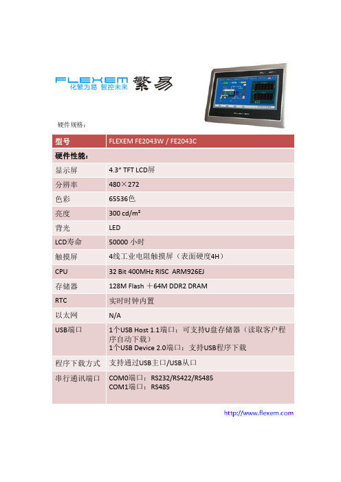
整机尺寸: 128mm×102mm×32mm(不含电源端子)
整机重量: 约500g/400g
端口说明:
1.电源端子
Pin1 DC24V Pin2 0V Pin3 FG
Pin讯口)
环境规格: 工作温度 -20~70℃/0~50℃ 存储温度 -30~80℃ 环境湿度 10~90%RH(无冷凝) 抗震性: 10 ~ 25 Hz (X、Y、Z方向 2G/30分钟) 冷却方式: 自然风冷 其它: 防护等级: 前面板符合IP65(配合平整盘柜安装),机身后壳符合IP20 机械机构: FE2043W: 前面板采用铝合金,表面硬化氧化着色,后壳采
Pin1 Rx- (B) (COM0 RS485)
Pin2 Rx+ (A) (COM0 RS485)
Pin3 Tx- (COM0 RS485) Pin5
Pin9
Pin4 Tx+ (COM0 RS485)
Pin5 GND
Pin6 TxD (COM0 RS232)
Pin7 D- (B) (COM1 RS485)
型号
FE2043W / FE2043C
电气规格:
额定功率 额定电压
< 4W DC 24V,可工作范围DC 18V~32V
电源保护 允许失电 CE & ROHS
具备雷击浪涌保护
< 5 mS
符合EN61000-6-2:2005 ,EN61000-6-4:2007 标准,符合ROHS 雷击浪涌±4KV,群脉冲±4KV;静电接触4K,空气放电8KV
Pin1
Pin6
Pin8 D+ (A)(COM1 RS485)
4寸TFT触摸屏指南书说明书
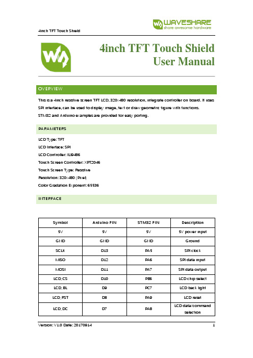
4inch TFT Touch ShieldUser ManualOVERVIEWThis is a 4inch resistive screen TFT LCD, 320x480 resolution, integrate controller on board. It uses SPI interface, can be used to display image, text or draw geometric figure with functions.STM32 and Arduino examples are provided for easy porting.PARAMETERSLCD Type: TFTLCD Interface: SPILCD Controller: ILI9486Touch Screen Controller: XPT2046Touch Screen Type: ResistiveResolution: 320x480 (Pixel)Color Gradation Exponent: 65536INTERFACESymbol Arduino PIN STM32 PIN Description 5V 5V 5V 5V power inputGND GND GND GroundSCLK D13 PA5 SPI clockMISO D12 PA6 SPI data inputMOSI D11 PA7 SPI data outputLCD_CS D10 PB6 LCD chip selectLCD_BL D9 PC7 LCD back lightLCD_RST D8 PA9 LCD resetLCD_DC D7 PA8 LCD data/commandselectionHOW TO USEHARDWARE CONFIGURATION•If there is ICSP interface on Arduino board, set the SPI Config switch onto ICSP position.(default)•If Arduino board has no ICSP interface, set the SPI Config switch onto the position that SCLK\D13, MISO\D12, MOSI\D11EXAMPLESWe provide Arduino UNO examples and XNUCLEO-F103RB examples for this screen.ARDUINO EXAMPLES1.Download the examples: 4inch TFT Touch Shield code.7z, and copy the libraries which are inArduino\lib folder of examples to the libraries folder which is under the installation directory of Arduino IDE.2.Before running the LCD_ShowBMP code, copy the pictures which is in the PIC folder to SDcard.3.Open the LCD_ShowBMP project with Arduino IDE, download to Arduino board.4.The Touch code use four sets of calibration values, could support painting operation in fourdirections. There are five colors which could be selected on the right. The size of paintbrush is 9 pixels by default. Users can also click the AD on screen to calibrate:Please use the stylus click the cross on the screen. The cross will always move until thescreen adjustment is completed.5.Following the prompt, click the red sign “+” one by one to finish the calibration.STM32 EXAMPLES1.Before running the code that display image. copy the pictures which is in the PIC folder toSD card. Then insert the LCD to NUCLEO or XNUCLEO board.2.Open the project with MDK, download to the NUCLEO or XNUCLEO development board.3.The LCD will first show some common functions: Draw dots, draw dotted line and solid line,rectangle, filled rectangle, circle and solid circle. Every figure keeps for 3s. You can change the size of dot, the width of lines and the size of the circles.4.The Touch code use four sets of calibration values, could support painting operation in fourdirections. There are five colors which could be selected on the right. The size of paintbrush is 9 pixels by default. Users can also click the AD on screen to calibrate:Please use the stylus click the cross on the screen. The cross will always move until thescreen adjustment is completed.5.Following the prompt, click the red “+” one by one to finish the calibration.Note:Image: 320x480, 24bit, bmp.SD card: FAT。
4.3英寸多色图形LCD显示器用户手册说明书

4.3inch Capacitive Touch LCDUser ManualOVERVIEWThis is a multicolor graphic LCD display, 4.3inch diagonal, 800x480 pixels.It is able to display 16,777,216 colors via the 24-bit RGB interface, supports up to 5-points capacitive touch control via I2C interface.Overview (1)Specificiations (3)Interface (3)Demo codes (4)Download Demo codes. (4)STM32F7 examples (4)Hardware connection (4)Expected result (6)STM32F4 examples (6)Hardware connection (6)Expected result (8)FAQ (9)Working voltage: 3.3V/5VLCD Interface:24-bit RGBLogic Level: 3.3VLCD Type:TFTDisplay Colors:16,777,216Resolution :800(H)RGB x 480(V) Display Size:95.04 (H) x 53.856 (V)mm Dot Pitch:0.1188(H) x 0.1122(V) mm Touch controller:GT911Touch Interface:I2CDimension:106 x 68(mm)DOWNLOAD DEMO CODES.Download demo codes from Waveshare wiki.https:///wiki/4.3inch_Capacitive_Touch_LCD#IntroductionUnzip it:STM32F429: Examples based on Open429I-C, whose chip is STM32F429IGT6. The project uses HAL librariesSTM32F746:Examples based on Open746I-C, whose chip is STM32746IGT6. The project uses HAL libraries. With Open746I-C, both RGB Header interface and RGB Cable interface are compatible, so we provide two examples for both interfaces.Clean.bat: Batch files sued to clean redundant files generated when compiling.STM32F7 EXAMPLESDevelopment board used is Waveshare Open746I-C, chip is STM32F746IGT6. The project uses HAL libraries.HARDWARE CONNECTIONFor this board, we provide two examples, with same functions. The only difference of them is that the touch interfaceRGB Header interface (Interface 1)RGB Cable interface (Interface 2), the only difference between Interface 1 is touch pins.EXPECTED RESULT1.Display a picture2.Display English and Chinese characters3.Draw point, line, rectangle and circle.4.Display the points where finger touch, supports up to 5-points touchSTM32F4 EXAMPLESDevelopment board used is Waveshare Open429I-C, chip is STM32F429IGT6. The project uses HAL libraries.HARDWARE CONNECTIONThe RGB Cable interface (Interface 2) is used for resistive touch screen, isn’t compatible with capacitive screen, therefore, we only provide RGB Header example (Interface 1) for this board. RGB Header Interface (interface 1)EXPECTED RESULT1.DISPLAY a picture2.Display English and Chinese characters3.Draw points, line, rectangle and circle4.Display points touched by fingers, supports up to 5-points touch1.Why the codes used RGB565 instead of RGB888 for color displaying?- The data of RGB888 are too much, required much more RAM. SDRAM is 16-bit input/output. If we use RGB888, we should save RGB data by writing several times, and cost much more times and CPU. In fact, even we use RGB565 to transmit data, LCD controller will convert it to RGB888 format and needn’t cost external CPU。
4.3 、5.0 、7.0寸导航参数
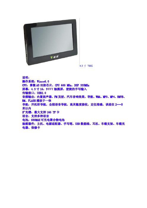
4.3寸700S说明:操作系统:Wince6.0CPU:掌微A5双核芯片,CPU 600 MHz,DSP 335MHz屏幕:4.3寸16:9TFT触摸屏,便捷的手写输入传输接口:USB2.0音频输出:内置扬声器,FM发射,汽车音响效果,导航、WMA、MP3、MP4、RMVB、RM、FLASH播放于一体导航:开机即导航,全程语音导航,高灵敏度接收,定位准确,误差在2---5米以内扩充槽:最大支持16G TF卡语言:支持多种语言电池:850MAH可充电聚合物电池装箱器件:主机、电源适配器、手写笔、USB数据线、耳机、车载支架、车载充电器、保修卡新增主要功能特色:1、主界面可以支持滑动动画翻页;2、提示的窗口可以拖动;3、小图标FM和喇叭音量调节分开,点喇叭小图标可进入音量设置;4、支持内存释放功能;5、语言增加繁体,变为中文简体-中文繁体-英文;6、系统设置下系统资源,支持看到内核版本号;7、已设置的时间关机后,可以保存。
8、内置存储空间为4G;9、TF卡支持16G,针对某些卡可以支持32G;10、支持RM视频格式;11、支持开机画面在系统设置中直接升级更改;12、原文件管理更改为GPS路径设置。
使用及配件注意事项:1、车充和座充请随机配套的,确保USB端口第4引脚悬空,不要和5V短接!2、地图请用能支持WinCE6.0平台的,端口和之前的不同,端口请设置为:COM1,波特率只要是标准的就OK。
3、USB连接线,请务必确保是专用USB连接线,要求编织屏蔽地,内阻小于0.4欧!5.0寸E900T型号和功能对应关系:E900T:带FM + 新固定电子狗预警功能功能说明:操作系统:Wince6.0CPU:掌微A5双核芯片,CPU 600 MHz,DSP 335MHz屏幕:5寸16:9高清TFT屏和手写触摸屏,便捷的手写输入传输接口:USB2.0音频输出:内置扬声器,FM发射,汽车音响效果,导航、WMA、MP3、MP4、RMVB、RM、FLASH播放于一体导航:开机即导航,全程语音导航,高灵敏度接收,定位准确,误差在2---5米以内扩充槽:最大支持16G TF卡语言:支持多种语言电池:1200MAH可充电聚合物电池机器尺寸:135*88.6*12.8 mm装箱器件:主机、电源适配器、手写笔、USB数据线、耳机、车载支架、车载充电器、保修卡新增主要功能特色:1、支持后台电子狗功能,任何功能界面下均能及时提醒固定预警点;2、提示的窗口可以拖动;3、小图标FM和喇叭音量调节分开,点喇叭小图标可进入音量设置;4、语言增加繁体,变为中文简体-中文繁体-英文;5、系统设置下系统资源,支持看到内核版本号;6、已设置的时间关机后,可以保存。
4.3寸TFT串口模组 4.3寸SPI液晶屏 显示屏

规格书·产品型号规格产品类型 基本型TJC4827T043_011N (N:无触摸屏) 产品型号 TJC4827T043_011R (R:4线电阻式触摸屏) 可视区对角线尺寸4.3 inch修订记录日期 描述 2016-03-10 编制数据手册 2016-04-06增加串口指令缓冲参数TJC4827T043_011XTJC4827T043_011X·外形参数参数 数据 说明颜色 65K(65536)色 16 bit调色板 5R6G5B120(L)×74(W)×5(H) TJC4827T043_011N外形尺寸120(L)×74(W)×6.2(H) TJC4827T043_011R显示屏尺寸 105.50mm(L)×67.20mm(W) 480×272像素模式可视尺寸(A.A.)95.04mm(L)×53.86mm(W) 480×272像素模式分辨率 480×272像素 可设置成272×480触控类型 4线精密电阻式触控次数 最少100万次背光模式 LED背光寿命(平均)>30,000小时250nit(TJC4827T043_011N) 可进行100级亮度调节亮度230 nit(TJC482T043_011R) 可进行100级亮度调节79.3g(TJC4827T043_011N)净重量93.8g(TJC4827T043_011R)·电器性能参数参数 测试条件 最小值 典型值 最大值 单位 工作电压 4.75 5 7 VVCC=+5V,背光亮度最大 - 250 - mA 工作电流SLEEP 模式 15 mA 推荐工作电源:5V 1A的直流稳压电源·工作环境和可靠性参数参数 测试环境 最小值 典型值 最大值 单位 工作温度 5V电压下,湿度60% -20 25 70 ℃ 储存温度 - -30 25 85 ℃ 工作湿度 25℃ 10% 60% 90% RH 三防处理 - - 无 - - ·接口性能参数参数 测试条件 最小值 典型值 最大值 单位 串口波特率 标准 2400 9600 115200 bps 串口输出电平(TXD)输出1,Iout=1mA 3.0 3.2 - V输出0,Iout=-1mA - 0.1 0.2 V输出1,Iout=1mA 2.0 3.3 5.0 V 串口输入电平(RXD)输出0,Iout=-1mA -0.7 0.0 1.3 V 接口电平 3.3V/5V TTL电平(非232电平)通讯模式 8,1,None用户接口方式 4Pin_2.54mm带锁扣SD卡接口 有(FAT32文件格式)最大支持32G MicroTF/SD卡TJC4827T043_011X扩展IO 无RTC 无·存储器特性存储器类别 参数 最小值 典型值 最大值 单位 FLASH存储器 字库图片储存空间 16 MB 用户存储 EEPROM 无运行内存(RAM) 控件/变量存储空间 3584 BYTE 串口指令缓冲 串口指令缓冲 1024 BYTE。
4.3寸屏 WXCAT43-TG3#001_V1.2
Product Specifications4.3” TFT-LCD with Touch Panel ModuleModel No. : WXCAT43-TG3#001PD Dept. PD Dept. PD Dept. Prepared byChecked byApproved bySun Jin Chwan-Gwo Chyau Dr.ChyauWANXIN IMAGE INC.4F, No. 65, Kuang-Fu North Rd., Hsin-Chu Industrial Park, Ho-Kuo, Hsin-Chu County, 303 Taiwan, R.O.C. Tel : 886-3-5976977 Fax : 886-3-5974074WANXIN IMAGE I N C O R P O R A T I O NContents1General Description (4)1.1Features (4)1.2Application (4)1.3General Specification (5)2Absolute Maximum Ratings (6)2.1Electrical Absolute Maximum Ratings (6)2.2Environment Absolute Maximum Ratings (7)3Electrical Characteristics (8)3.1TFT-LCD Module (8)3.2Back-Light Unit (8)3.3Touch Panel (8)4Optical Specification (9)4.1TFT-LCD Module (9)4.2Touch Panel (9)5Block Diagram (13)5.1TFT-LCD Module (13)5.2Touch Screen Panel (13)6Interface Specification (14)7Interface Introduction (16)7.124-bit RGB interface timing (16)7.2Power ON/OFF Control (16)7.3DC Characteristics (17)7.4AC Characteristics (18)8Outline Dimension (22)9Package (24)10Precautions (25)10.1Handling (25)10.2Storage (25)10.3Operation (25)10.4Touch Panel Mounting Notes (26)10.5Others (27)1 General DescriptionWXCAT43-TG3#001 is a transmissive type a-Si TFT-LCD (amorphous silicon thin film transistor liquid crystal display) module, which is composed of a TFT-LCD panel, a driver circuit, a backlight unit, and a 4-wires analog resistive type touch panel. The panel size is 4.3 inch and the resolution is 480×272. The panel can display up to 16.7M colors and is suitable for portable device display application.1.1 FeaturesLow power consumption.Ambient Temperature ()℃A l l o w a b l e F o r w a r d C u r r e n t (m A )8 Outline Dimension See next page.23/2810 PrecautionsPlease pay attentions to the followings as using the LCD module.10.1 Handling(a) Do not apply strong mechanical stress like drop, shock or any force to LCDmodule. It may cause improper operation, even damage.(b) Because the polarizer is very fragile and easy to be damaged, do not hit, press orrub the display surface with hard materials.(c) Do not put heavy or hard material on the display surface, and do not stack LCDmodules.(d) If the display surface is dirty, please wipe the surface softly with cotton swab orclean cloth.(e) Avoid using Ketone type materials (e.g. Acetone), Toluene, Ethyl acid or Methylchloride to clean the display surface. It might damage the polarizer permanently.The recommended solvents are water and Isopropyl alcohol.(f) Wipe off water droplets or oil immediately.(g) Protect the LCD module from ESD. It will damage the LSI and the electroniccircuit.(h) Do not touch the output pins directly with bare hands.(i) Do not disassemble the LCD module.10.2 Storage(a) Do not leave the LCD modules in high temperature, especially in high humidity fora long time.(b) Do not expose the LCD modules to sunlight directly.(c) The liquid crystal is deteriorated by ultraviolet. Do not leave it in strong ultravioletray for a long time.(d) Avoid condensation of water. It may cause improper operation.(e) Please stack only up to the number stated on carton box for storage andtransportation. Excessive weight will cause deformation and damage of carton box.10.3 Operation(a) When mounting or dismounting the LCD modules, turn the power off.(b) Protect the LCD modules from electric shock.The corner part has conductivity. Do not touch any metal part after mounting.10.5 Others(a) If the liquid crystal leaks from the panel, it should be kept away from the eyes ormouth.(b) For the fragility of polarizer, it is recommended to attach a transparent protectiveplate over the display surface.(c) It is recommended to peel off the protection film on the polarizer slowly so that theelectrostatic charge can be minimized.<This last page is left blank>。
广州大彩串口屏F系列4.3寸电容触摸屏数据手册
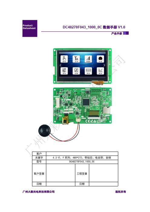
产品手册DC48270F043_1000_0C 数据手册V1.0V1.0V10.V1.0广州大彩光电科技有限公司版权所有目录1.硬件介绍 (1)1.1硬件配置 (1)1.2调试工具 (1)2.产品规格 (2)3.可靠性测试 (4)4.产品尺寸 (5)5.产品定义 (6)6.产品架构 (7)7.开发软件 (8)7.1什么是虚拟串口屏 (8)7.2Keil与虚拟串口屏绑定调试 (9)1.硬件介绍以下主要介绍产品的一些硬件配置信息和调试所需工具。
1.1硬件配置以下为该产品硬件配置图,如图1-1所示。
图1-1硬件配置图1.2调试工具以下为该产品调试工具参考图,如图1-2所示。
图1-2调试工具图2.产品规格◆产品参数产品型号DC48270F043_1000_0C(电容触摸)产品系列F系列核心处理器*32位大彩深度定制专用处理器操作系统嵌入式实时操作系统,上电即可运行协议类型大彩组态指令集尺寸 4.3寸分辨率480*272存储空间64Mbit字库内置矢量字体,边缘抗锯齿处理,包含任何大小点阵ASCII、GBK、GB2312、UNICODE 字库,可自定义任意电脑字体显示图片存储支持JPEG、PNG(半透/全透)压缩,支持任意大小图片存储。
累加可存储约125张全屏图片(按大小63KB/张计算,不建议BMP格式)。
图片压缩比不同,此值会上下浮动颜色65K色,16位RGB电压5-15V(误差±0.2V)功耗背光最亮:1.2W;关背光:0.65W通讯接口RS232/TTL(出厂默认232电平)接口规格默认PH2.0-8P,可选配FPC1.0-10P图片下载UART/SD卡(U盘预留)外部键盘不支持实时时钟(RTC)选配(支持倒计时、定时器、年月日等时间显示)屏有效显示区(AA)长×宽=96.0mm×54.9mm产品尺寸长×宽×高=121.9mm×74.7mm×13.7mm配套上位机软件VisualTFT®AV输入不支持声音播放WAV、MP3音频格式(喇叭4Ω2W,单声道),与图片共用存储空间。
4.3寸40PIN高亮显示屏规格书
SPECIFICATION NO.:CXT430C10H29-1200P40NACCEPTEDBYCUSTOMERProduct: 4.3” TFT 480(RGB)*272 PixelsVerson: V00Date: 2013/11/23APPROVED CHECKED PREPARED—————————————————————————————————1Catalog:N0. ContentsPage 1 History Verson1 2 Mechanical Description 2 3 Mechanical Drawing 3 4 Interface Definition 4 5 Interface Timing5-6 6 Absolute Maximum Ratings 7 7 DC Characteristics 7 8 Blacklight7-8 9 Optical Specification 8-9 10 Reliability testing 10 11 Inspection Standard 11-12 12 Precaution 12-131. History VersonSample versonDoc.versonDate Discription ModifyV00 V00 2013-11-23 First issue Ljj—————————————————————————————————12.Mechanical DescriptionName Content Unit Outline Size 105.50 (W) * 67.20 (H) * 2.90(T) mmModule size 4.3 (V.A) inchResolution 480(RGB)* 272 Pixels -Viewing size 95.04(W) * 53.86(H) mmPixel size 0.198 * 0.198 mmLCD Type TFT (262K)/ Transmissive / Positive - Viewing Angle 6 H - Driver IC OTA5180A - Backlight Type 6 Serial 2 Paralle LEDs - Interface Type 24 Bit RGB -—————————————————————————————————23.Mechanical Drawing—————————————————————————————————3PIN NO. PIN Name Funtion Description1 LEDK back light power supply negative2 LEDA back light power supply positive3 GND Ground4 VCC Power supply5-12 R0-R7 Red Data13-20 G0-G7 Green Data21-28 B0-B7 Blue Data29 GND Ground30 CLK Colock signal31 DISP Display on/off32 HSYNC Horizontal sync input in RGB mode33 VSYNC Vertical sync input in RGB mode34 DE Data enable35 NC No Connection36 GND Ground37 NC(YU) NC(touch panel Y-up)38 NC(XL) NC(touch panel X-left)39 NC(YD) NC(touch panel Y-bottom)40 NC(XR) NC(touch panel X-right) —————————————————————————————————4—————————————————————————————————55.1 Reset Timing5.2 RGB Interface Timing5.3 AC Timing Diagram—————————————————————————————————66. Absolute Maximum Ratings:Name symbol Min Type Max Unit Operation Temperature T OP-20 - 70 ℃ Storage Temperature T ST-30 - 80 ℃7. DC CharacteristicsName Symbol Min Type Max Unit Logical Voltage VDD 3.0 3.3 3.6 V Input High Voltage V IH0.8IOVCC - IOVCC V Input Low Voltage V IL-0.3 - 0.2IOVCC V Output High Voltage V OH0.8IOVCC - - V Output Low Voltage V OL- - 0.2IOVCC V Current Consumption IDD 4 10 - mA 8.Blacklight:Name Min Type Max Unit Current -40 50 mA Voltage -19.2 21 VPowerConsumption-768 - mWluminance 1000 1200 - CD/M2 (Note1)Luminanceuniformity75% 80% - (Note2) X ColorCoordinates0.27 0.28 0.31 -Y ColorCoordinates0.27 0.28 0.31 - Note1:This luminance is tested with assembling the LCD.Note2:Definition of Luminance Uniformity.—————————————————————————————————7—————————————————————————————————89. Optical SpecificationNameSymbol Min Type Max Unit Transmittance rate T(%) - 4.6 - % Contrast ratio C/R 250 350 - - Response timeTr+Tf- 45 - msViewing AngleθU50 60 - degree (C/R>10)θD 60 70 - θL 60 70 - θR6070-*Viewing angle descriptin:—————————————————————————————————9*Contrast rate description(CR) :Tested in the center of the LCM panel*Response time description : Sum of TR and TF—————————————————————————————————1010.Reliability testing :*One single product test for only one item. * Judgment after test: keep in room temperature for more than 2 hours. - Current consumption < 2 times of initial value - Contrast > 1/2 initial value - Function: work normallyItemNo Name Condition Remark 1 High temperature Operating 70°C , 168Hours Finish product (With polarizer) 2 Low temperature Operating -20°C , 168 Hours Finish product (With polarizer) 3 High temperature Storage80°C , 168 Hours Finish product (With polarizer) 4 Low temperature Storage-30°C , 168 Hours Finish product (With polarizer) 5High temperature & humidity Storage60°C , 90%RH, 168 HoursFinish product (With polarizer) 6 Thermal Shock Storage(Nooperation) -20°C , 30min.<=> 70°C , 30min.10 CyclesFinish product (With polarizer) 7 ESD testVoltage:+8KV R:330 ohm,C:150pF Air discharge,10 times Finish product (With polarizer) 8 Vibration test10 => 55 =>10 => 55 => 10 Hz, within 1 minute;Amplitude:1.5mm.15 minutes for each Direction( X,Y,Z )Finish product (With polarizer) 9 Drop testPacked, 100CM free fall 6 sides, 1 corner, 3edgesFinish product (With polarizer)—————————————————————————————————1111.Inspection Standard11.1 Defect Defination11.2 StandardNo. D efect ClassDefinationContent1重缺陷(MA )影响显示的功能缺陷短路、断路、缺划、大电流、视角错、漏液、显示不清等严重外观缺陷产品尺寸不符、漏部品等 2 轻缺陷(MI ) 不影响产品功能,但对产品外观有影响反黑/反白点、偏光片缺陷、针孔、污点No. Item Inspection StandardClassification of defects1 显示状态 不显、显示乱码、多划、少划、少画面、视角错、闪烁等均不允许重缺陷无法用文字描述的现象,必要时制定限度样板进行参考。
专业4.3寸TFT触摸屏资料
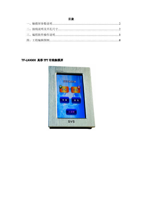
目录一、触摸屏参数说明 (2)二、接线说明及开孔尺寸 (2)三、编程软件操作说明 (3)四、工程编辑图例 (6)TF-LK4300 真彩TFT有线触摸屏一、触摸屏参数说明1.处理器CPU:64位ARM处理器运行速度:60MIPS,启动时间不超过2S2.存储器64MByte RAM和128M NORFLASH3.显示显示屏类型:TFT显示屏显示像素:480X272屏幕尺寸:对角4.3英寸高宽比:16:9对比度:9级可调显示颜色:16位真彩可视角度:水平正负60度,垂直正负35度按键:3D/2D按键和多种显示效果4.电源外接适配器: 1.5A@5VDC。
输入电源100V~240V 50/60HZ 5.通讯通用RS-232信号传输计算机管理端口: RS-232下载通讯端口6.界面语言支持支持各种语言显示屏显示7.触摸屏支持横放和竖立等任意方向放置方式8.外壳豪华磨砂耐磨铝面板9.安装方式可墙面及桌面横向或纵向嵌入式安装二、接线说明及开孔尺寸RS-232串口接线说明:2脚发送,3脚接收,5脚接地开孔尺寸图(mm):三、编程软件操作说明1、打开触摸屏编程软件后,选择“工程”>>>“新建”可以选择一个文件位置和自定义文件名,新建一个工程。
2、选择“工程”>>>“加载图片…”,然后选择格式为“BMP”或“JPG”的图形文件加载。
(所加载的图片需要经过图形处理软件进行处理,附赠光盘里面包含有图形处理软件以及一些我公司几款代表主机的标准程序)。
3、加载图片以后,在“工程设计”树形结构里面,排在第一位的页面默认为首页,可根据要求按箭头上下切换。
A、所编辑的图片,每一个页面由两张图片构成,第一张为弹起状态图片,第二张为按下状态图片。
所有触点都在弹起状态图片绘制即可。
B、在可编辑区域点击鼠标右键会出现一个红色可编辑区域,区域大小可根据图片按钮大小的要求改变。
C、选择一个红色区域,在属性框填写相应属性。
TFT_4.3模块编程手册v2.0
LCD043T480272WD使用手册V2.0目 录1产品简介 (1)1.1 主要功能与基本参数 (1)1.2 模块结构 (1)1.3 系统环境 (2)2液晶显示器介绍 (4)2.1 显示RAM区映射情况 (4)2.2 操作时序 (5)2.3 TFT模块显示特性 (7)2.3.1窗口模式 (7)2.3.2特定颜色屏蔽模式 (8)2.3.3双图层显示 (9)2.3.4填充方向控制 (10)2.3.5自动2D填充 (10)2.4 控制寄存器 (11)2.4.1控制寄存器介绍 (11)2.4.2TFT驱动模块寄存器说明 (11)3TFT模块控制流程 (14)3.1 TFT驱动模块控制方法 (14)3.2 TFT驱动模块的基本操作 (15)3.2.1寄存器写入操作的流程图 (15)3.2.2数据写入/读出操作流程图 (15)3.2.3系统寄存器设置操作 (16)3.3 TFT驱动模块模块底层接口程序参考 (19)3.3.1模块与MCS51的连接 (19)3.3.2与LCD模块连接的端口定义 (19)3.3.3TFT驱动模块基本操作函数 (20)3.3.4初始化TFT驱动模块以及绘制一个点 (22)4驱动程序移植 (24)1 产品简介1.1 主要功能与基本参数TFT 驱动模块是一块高画质的TFT 真彩LCD 驱动模块,模块内置LCD 控制器以及驱动器,外部8位或16位的8080总线接口,可方便的使用单片机对其进行连接控制,具有编程方便、易于扩展等良好性能。
TFT 驱动模块内部的控制器包含有显示缓存,无需外部显示缓存,而其背光可由指令控制(128级可调)。
TFT 驱动显示模块的基本参数如下表:项目规格单位注备显示点阵数 480×RGB ×272 Dots LCD 尺寸 4.3(对角线) 英寸 LCD 模式 65K TFT16位色深度总线 8位或16位Intel 80总线工作电源电压 5 V 端口电压3.3 V1.2模块结构TFT 驱动模块在PCB 背板上集成了一个LCD 控制器以及显存、背光控制等电路;而模块以DIP 的双排插针引出控制接口(8位/16位8080并行总线)模块以便于用户连接。
TFT-4.3 数据手册V1.00
广州周立功单片机科技有限公司
TFT-4.3
液晶套件
1.1 主要产品特性
产品类别 外形尺寸 有效显示区域尺寸 液晶屏类型
LCM 显示色彩 分辨率(宽×高) 对比度 响应时间 可视角度 背光类型 背光亮度
工作环境
用户接口 触摸屏
1.2 环境参数
表 1.1 产品特性
标准型(Standard)
126.0(长)mm × 80.0(宽)mm × 13.8(厚)mm
3.2 温湿度测试
放电极性 +/+/-
表 3.2 湿度测试
项目 高温工作 低温工作
60℃,4 小时 -20℃,4 小时
测试条件
测试现象 自恢复正常显示
正常显示
测试结果 通过 通过
测试结果 工作正常 工作正常
产品数据手册
©2013 Guangzhou ZLG MCU Technology Co., Ltd. 4
TFT-4.3 使用了 4.3 英寸TFT真彩液晶屏,使用广州周立功单片机科技有限公司自定义的 数据接口,带有 4 线电阻触摸屏;拥有宽屏幕、高亮度、低功耗的优越性能。产品实物如图 1.1和图 1.2所示。
图 1.1 产品实物——正面
图 1.2 产品实物——背面
产品数据手册
©2013 Guangzhou ZLG MCU Technology Co., Ltd. 1
图 2.1 引脚接口图
表 2.1 引脚说明
引脚
名称
1、2
VCC(5V)
3 4、5
GND VDD_LCD(3.3V)
6
TS_XM
7
TS_XP
8
TS_YM
9 10、11
4.3寸HDMI触摸屏说明书

4.3inch HDMI LCD (B)User Manual OVERVIEWThis is a 4.3inch capacitive touch screen, 800x480 resolution, HDMI interface, supports various system.FEATURES⚫IPS screen, 800x480 hardware resolution, configurable by software (up to 1920x1080)⚫Supports popular mini PCs such as Raspberry Pi, BB Black, Banana Pi, as well as general desktop computers⚫When works with Raspberry Pi, supports Raspbian/Ubuntu/Kali/Retropie/WIN10 IOT, driver free⚫When work as a computer monitor, supports Windows 10/8.1/8/7, five-points touch, and driver free⚫Multi languages OSD menu, for power management, brightness/contrast adjustment, etc.⚫ 3.5mm audio jack, speaker connector, supports HDMI audio outputOverview (1)Features (1)How to use (3)Workign with PC (3)Connection (3)Configure the touch display (4)Working with Raspberry Pi (6)Setting and connection (6)Orientation (7)Keys (9)WORKIGN WITH PCTo work with common desktop computer, this LCD can support Windows7/8/8.1/10 OS.CONNECTION1.Turn on the backlight switch on the backside of LCD2.Connect Touch Interface of LCD to one of USB ports of PC3.Connect HDMI (Display) interface of LCD to HDMI port of PC4.Connect earphone to HP interface or speaker to speaker interface of LCD if requireaudio output.After connecting and starting, you can see that the LCD can display the desktop of OS like below (Some of PC cannot support hot-plug, in this case you need to restart your PC)CONFIGURE THE TOUCH DISPLAYAs we know, the touch screen connected is set to control the main display by default, sometimes we need to make the touch to control other display than the main display if we set the touch screen as second display. Herein we show you how to configure it.1.Open Tablet PC Settings from Control Panel2.Open the Tablet PC Settings, and click Setup…:3.Following the hint to finish setting:hints:Tap this screen with a single finger to identify it as the touchscreen. If this is not the Tablet PC screen, press Enter to move to the next screen. To close the toll, press Esc.For example:I connect a big size display and one touch screen to my PC (Windows 10), the bigdisplay is recognized as display 1 (the main display), the touch screen isrecognized as display 2 (the second display). Before tablet setting, the touchscreen controls the main display if I touch it. Now I want to make the touch screen to control itself-the second display.So, I click Setup…, the hint appears on display 1 and display 2 is white. I pressEnter, the hint turns to display 2 and display 1 is white. I tap the center of thetouch screen (display 2). The setting is finish, and now if I tap the touch screen, I can control the display 2 with the touch screen instead of main display.WORKING WITH RASPBERRY PIThis LCD supports Raspbian, Ubuntu Mate, Kali, Retropie and WIN 10 IOT1. To work with Raspberry Pi, you need to configure resolution of OS manually for properly displaying, herein we take Raspbian as example.SETTING AND CONNECTION1.Download the lastest Raspbian image from Raspberry Pi website.2.Writing the image to SD card3.After writing, open and modify the config.txt file, which located at root directory(BOOT) of SD card, append/modify these lines to config.txt file【Note】There should not be spaces in both sides of equal-sign. Sometimes you may need to change hdmi_cvt 800 480 60 6 0 0 0 to hdmi_cvt=800 480 60 6 0 0 0 if LCD cannot work with the configuration above.4.Save and exit. Insert the SD card to Raspberry Pi5.Turn on the backlight switch on the backside of LCD6.Connect Touch interface of LCD to USB port of Raspberry Pi7.Connect HDMI interface of LCD to HDMI port of Raspberry Pi8.Power on Raspberry Pi1There aren’t calibration tools for WIN 10 IOT, we recommend you capacitive screen if you want to use WIN 10 IOT.ORIENTATIONDisplay Rotating1.To rotating the display, you can append this statement to the config file2.Reboot the Raspberry PiTouch RotatingNote: To rotate the touch, you can re-compile the kernel as well. There is an example for reference (use 7inch HDMI LCD (C).)⚫Re-Compilation MethodAnother way, you can set the libinput.1.Install libinput2.create an xorg.conf.d folder3.copy file 40-libinput-conf to the folder which we created4.Append a statement to touchscreen part of the file as below:5.save and reboot your PiAfter completing these steps. The LCD could rotate 90 degree both display and touch. 【Note】90 degree: Option "CalibrationMatrix" "0 1 0 -1 0 1 0 0 1"180 degree: Option "CalibrationMatrix" "-1 0 1 0 -1 1 0 0 1"270 degree: Option "CalibrationMatrix" "0 -1 1 1 0 0 0 0 1"KEYSPower: Open/Close LCD display (backlight)Menu: Open menu/OKUp/Left: DirectionDown/Right: DirectionExit: Return/Exit【Note】You can close display by button power toreduce consumption.。
- 1、下载文档前请自行甄别文档内容的完整性,平台不提供额外的编辑、内容补充、找答案等附加服务。
- 2、"仅部分预览"的文档,不可在线预览部分如存在完整性等问题,可反馈申请退款(可完整预览的文档不适用该条件!)。
- 3、如文档侵犯您的权益,请联系客服反馈,我们会尽快为您处理(人工客服工作时间:9:00-18:30)。
目录
一、触摸屏参数说明 (2)
二、接线说明及开孔尺寸 (2)
三、编程软件操作说明 (3)
四、工程编辑图例 (6)
TF-LK4300 真彩TFT有线触摸屏
一、触摸屏参数说明
1.处理器
CPU:64位ARM处理器
运行速度:60MIPS,启动时间不超过2S
2.存储器
64MByte RAM和128M NORFLASH
3.显示
显示屏类型:TFT显示屏
显示像素:480X272
屏幕尺寸:对角4.3英寸
高宽比:16:9
对比度:9级可调
显示颜色:16位真彩
可视角度:水平正负60度,垂直正负35度
按键:3D/2D按键和多种显示效果
4.电源
外接适配器: 1.5A@5VDC。
输入电源100V~240V 50/60HZ 5.通讯
通用RS-232信号传输
计算机管理端口: RS-232下载通讯端口
6.界面语言支持
支持各种语言显示屏显示
7.触摸屏支持横放和竖立等任意方向放置方式
8.外壳
豪华磨砂耐磨铝面板
9.安装方式
可墙面及桌面横向或纵向嵌入式安装
二、接线说明及开孔尺寸
RS-232串口接线说明:
2脚发送,3脚接收,5脚接地
开孔尺寸图(mm):
三、编程软件操作说明
1、打开触摸屏编程软件后,选择“工程”>>>“新建”可以选择一个文件位置和自定义文
件名,新建一个工程。
2、选择“工程”>>>“加载图片…”,然后选择格式为“BMP”或“JPG”的图形文件加载。
(所加载的图片需要经过图形处理软件进行处理,附赠光盘里面包含有图形处理软件以及一些我公司几款代表主机的标准程序)。
3、加载图片以后,在“工程设计”树形结构里面,排在第一位的页面默认为首页,可根据
要求按箭头上下切换。
A、所编辑的图片,每一个页面由两张图片构成,第一张为弹起状态图片,第二张为按
下状态图片。
所有触点都在弹起状态图片绘制即可。
B、在可编辑区域点击鼠标右键会出现一个红色可编辑区域,区域大小可根据图片按钮
大小的要求改变。
C、选择一个红色区域,在属性框填写相应属性。
各属性说明如下。
“左”,“右”,“上”,“下”指示的是触点区域坐标位置。
“切换图片”:填写跳页图片的名称,即按下该区域按钮即将切换到哪张图片。
“背景图片”:填写按下当前区域按钮时按下状态的图片名称。
“发送代码”:填写该区域按钮被点击的时候所需要发送的16进制代码。
4、程序上传说明
A、上传准备:
上传之前请确认电脑的数据线已经和触摸屏连接,并且触摸屏在正常供电。
系统连机:
选择“操作”>>>“系统连机”,弹出“连接”对话框以后选择正确的串口,此时波特率
默认为115200即可,点击“连接”按钮,连接成功以后在编程软件最右下角状态栏可以看
到当前连接状态如图
B、程序传送
A、“下载全部编辑图”:传送所有图片。
B、“下载编译”:传送编程程序,包括触点和代码。
C、完成
所有程序传送完成以后,都需要重新进行系统连机,操作步骤为:选择“操作”>>>“系统连机”>>>“断开”,然后重新连机,并且把“波特率”修改为“9600”后再点击“连接”。
5、系统设置说明
1.选择“操作”>>>“系统连机”>>>弹出“连接”对话框后选择连接,如下图所示:
2.再次选择“操作”>>>“系统设置”>>>弹出“输入密码”对话框,密码为:123,然后点击确定,如下图所示:
然后会进入到系统设置的对话框页面:
可以设置屏幕背光的亮度,对触摸屏进行校准,并且可以设置屏保,将“开启屏保”选项打上勾以后,分别有30秒、1分钟、2分钟的屏保时间选择,根据实际情况及个人需求而定。
四、工程编辑图例
工程程序编辑图(横向):
工程程序编辑图(竖向):。
