调光器使用说明书-后切
led调光器使用方法

led调光器使用方法
LED调光器是一种用于控制LED灯光亮度的设备,它可以帮助
用户实现灯光的调节和控制。
在本文中,我们将介绍LED调光器的
使用方法,帮助大家更好地了解如何使用这一设备。
首先,LED调光器通常具有多种控制方式,包括旋钮式、触摸式、遥控式等。
用户可以根据自己的需求和喜好选择合适的控制方式。
其次,使用LED调光器时,首先需要将LED灯和调光器连接好,并确保电源已经接通。
接下来,根据调光器的说明书,进行相应的
操作,例如旋动旋钮、触摸屏操作或者遥控器控制,来调节LED灯
的亮度。
此外,LED调光器通常还具有定时、记忆、情景模式等功能,
用户可以根据自己的需求进行设置和调节。
比如可以设置定时开关灯,或者通过情景模式来实现不同场景下的灯光效果切换。
需要注意的是,使用LED调光器时,要根据LED灯的功率和调
光器的功率匹配情况来选择合适的调光器,以免造成设备损坏或者
不良使用效果。
总的来说,LED调光器是一种非常实用的灯光控制设备,能够帮助用户实现灯光的调节和控制,提升居家、办公等环境的舒适度和美观度。
希望通过本文的介绍,大家能更好地掌握LED调光器的使用方法,从而更好地享受LED灯光带来的便利和舒适。
调光灯光控制器使用说明

DK-503调光控制器使用说明书(1.1)深圳市必爱歌电子科技有限公司版本作者日期内容1.0 丁度旭2010.09.02 创建1.1 胡冬贤2011.11.11 增加三路单独控制,线性调光。
DK-503调光灯光控制器使用说明书(V1.1)请注意:DK-503和DK-05、DK-08的工作状态设置方法不一样一、DK-503调光灯光控制器基本参数:产品规格:DK-503灯光控制器5路开关控制,3路调光控制工作电压:220V-250V 功耗10W;外型尺寸:220*125*55 (长*深*高)单路负载:可调灯光1500W(7A)开关灯光6000W(30A)产品特点: a、三路调光可实现每路独立控制。
b、每路的亮度开关记忆功能。
d、调光亮度变化渐变,避免视觉冲击。
e、调光每路可编入场景中,且不同场景亮度不同。
F、灯光控制器上可直接按键操作设定灯光亮度。
g、可恢复出厂默认值。
二、DK-503前面板图:前面板自左至右八个按键有两种含义。
含义一:“通道”对应后面板连接的八路负载,按键上方的LED灯表示状态,正常工作时,LED亮表示该路负载接通为亮;设置状态时,LED亮表示该路负载受控制。
含义二:“场景”代表本机的灯光组合(注:另一叫法为“场景”),有八个场景A-H和开机场景共九种场景。
前面板最右边按键代表“确认设置”键,其上方的LED代表“设置指示灯”。
后面板灯光接线图灯控墙板举例(用网线连接灯光墙板至DK系列墙板的任意一个LINK口)三、出厂默认设置:1、出厂默认灯光场景:出场默认开机场景:通道1-8连接的8个灯全亮。
场景A(动感):通道1灯的亮灭控制场景B(柔和):通道2灯的亮灭控制场景C(明亮):通道3灯的亮灭控制场景D(抒情):通道4灯的亮灭控制场景E(未取名):通道5灯的亮灭控制场景F(未取名):通道6灯的亮灭控制场景G(未取名):通道7灯的亮灭控制场景H(未取名):通道8灯的亮灭控制2、什么是“灯光场景”:多路灯光的亮灭组合而成的场景就是所谓的“灯光场景”。
萤石 智能照明-调光驱动器 CS-HAL-WD3-2V150G 使用说明书

产品简介安装设备WD3是一款新型无线调光控制设备(以下简称“设备”),将设备关联到萤石网关并添加到“萤石云视频”客户端,配合灯带一起使用,可以实现亮度和色温调节、联动控制等功能。
*RESET按键长按5秒:设备重置并进入添加模式装箱清单用户指南×1调光驱动器×1连线示意图RESET按键设备的安装位置需要有零线;当环境有多个零线回路时,需保证它和所控制的灯处于同一零线回路中。
请勿在潮湿、污染、腐蚀的环境中使用。
请专业人员按照电工规范和产品说明书要求进行安装、调试。
产品可直接平放在吊顶内,无需安装。
安装时务必关闭总闸,开启总闸前请确认是否安装正确,避免发生危险。
.. . ..完成示意图L下载“萤石云视频”登录“萤石云视频”客户端,选择添加设备,进入扫描二维码界面。
21扫描下面的二维码,下载并安装。
手机扫描二维码下载“萤石云视频”客户端-20℃~50℃0%~95%RH Zigbee 3.0220-240V~,50/60Hz 工作温度工作湿度通讯方式电源电压IP20IP20防水等级防尘等级规格参数版权所有©杭州萤石软件有限公司。
保留一切权利。
本手册的任何部分,包括文字、图片、图形等均归属于杭州萤石软件有限公司或其关联公司(以下简称“萤石”)。
未经书面许可,任何单位或个人不得以任何方式摘录、复制、翻译、修改本手册的全部或部分。
除非另有约定,萤石不对本手册提供任何明示或默示的声明或保证。
关于本产品本手册描述的产品仅供中国大陆地区销售和使用。
本产品只能在购买地所在国家或地区享受售后服务及维保方案。
关于本手册本手册仅作为相关产品的指导说明,可能与实际产品存在差异,请以实物为准。
因产品版本升级或其他需要,萤石可能对本手册进行更新,如您需要最新版手册,请您登录萤石官网查阅(w w )。
萤石建议您在专业人员的指导下使用本手册。
商标声明· 、 、 为萤石的注册商标。
·本手册涉及的其他商标由其所有人各自拥有。
CODE PD 系列数码调光器 说明书 VER1.51
Ver 1.51C OD EPD 系列数码调光器使用手册顾德电子有限公司CODE ELECTRONIC CO., LTD.欢迎使用CODE PD系列数码调光硅箱。
本设备采用国际通用的DMX-512/1990协议标准的数码控制信号,可与采用该协议标准输出的调光控制台配合使用,构成数码式调光控制系统。
本设备的电磁干扰抑制效果极佳,可广泛应用于电视演播、剧院、文艺团体、歌舞厅等调光控制系统。
安全警告必须连接良好性能的接地地线,确保操作人员及设备的安全。
机内有高电压,切勿擅自打开,确保生命安全!1. 技术参数z DMX512数码光电隔离输入z调光回路:产品型号调光回路负载最大电流220V可接负载PD 1202 12 每路10A 每路2KWPD 604 6 每路20A 每路4KWPD 606 6 每路30A 每路6KWz 2048级调光精度。
z 10种调光曲线,各通道独立选择。
z 0-20%预热可调,各通道独立设置。
z软启动功能,延长灯泡寿命z控制信号中断时自动保持各通道调光值,保证不会产生黑场。
z可储存24个场景,可脱离控台独立预置、调用场景;可手动调光。
z高精度过零检测,各通道输出一致性好。
z高性能抗干扰电感器,谐波分量少,电磁噪音小。
z调光回路双重保险装置:过流及短路电子保护+高速空气开关。
z独立的过载及短路保护,功率器件过热保护,异常状况解除后自动恢复输出。
z根据工作温度自动调节散热风扇速度z具有输出限压功能,当电源电压高于本地电压系统标准值时,输出回路输出自动限制在本地电压标准值附近,保证灯泡安全运行。
z DMX接收地址设置及显示z电源频率自动跟踪及显示z各相电压实时检测及显示z工作温度实时检测及显示z异常状况警告显示z DMX信号输入连接器:XLR-D3Mz DMX信号直通连接器:XLR-D3Fz电源:AC100-240V, 50-60Hz, 三相或单相,50-60Hzz空载时功率消耗:6VAz尺寸与重量:产品型号尺寸重量482mm×133mm×510mm 19.3kgPD1202 19”3U,PD 604 19”3U, 482mm×133mm×510mm 18.5kgPD 606 19”3U, 482mm×133mm×510mm 20.9kg2. 面板与后板装置PD1202PD 604PD 6063. 主电源连接本设备可采用三相交流电源供电(不需要确定相序关系),也可采用单相交流电源供电。
前后沿调光

调光器1. 调光器基础知识调光器是一种用来改变电光源的光通量、调节照度的照明配件,广泛应用于家庭照明、剧场舞台、酒店客房、场馆展厅等场合.从原理上讲,所有调光器都是通过改变电光源的输入电流来获得不同强度的光输出,其控制方法包括改变加在负载上的电压幅值和改变电流流经负载的时间两种方式,前者直接改变了电流有效值,而后者是在交流电的半波内控制电流导通的时间及次数来实现的.1.调光器的分类调光器有很多种类别,按电源不同可以分为交流调光和直流调光,按控制电路的原理可以分为幅值调光和相位调光,按开关器件的种类可以分为无源调光和有源调光,按光线变化的级别可以分为分段调光和无极调光,按负载类型可以分为对电光源的直接调光和对照明控制器的间接调光等,下面对调光器的分类作综合介绍.1.1调幅式调光1.1.1可变电阻器调光可变电阻器调光是最早出现的调光方法,通过在白炽灯照明回路中串接一只大功率可变电阻器,调节可变电阻器就可以改变流过白炽灯的电流值,从而改变灯光亮度.这种调光方式在交直流电源回路中都可使用,并且不会产生无线电干扰,但由于可变电阻的功耗高、发热大,导致系统的效率很低,一般只作为原理演示使用.1.1.2自耦调压器调光用一个自耦调压器串接在交流回路中,通过调节电刷的位置来改变供给白炽灯的电压幅值,从而改变灯光亮度.虽然自耦调压器体大笨重,还有工频噪音,但由于系统效率较高,增减负载也不影响调光等级,在早期曾经大量用于舞台调光.1.1.3二极管分档式调光电路这个电路由一只三档开关控制,分别作全电压供电、半波供电和关断控制.这里的二极管可以看成是一个工作在导通状态的单向可控硅(SCR),这种调光方式是调幅式调光到相位调光的过渡类型.由于白炽灯半波供压是一个固定电压值,不能任意调节,并且白炽灯在半波电压下会轻微闪烁,所以这种电路的实用性不是很好.1.2调相式调光调相式调光是通过调节交流电每个半波的导通角来改变正弦波形,从而改变交流电流的有效值,以此实现调光的目的,也称为“斩波式”调光.调相式调光包括前沿相位控制和后沿相位控制(也称前切和后切)两种类型,工作原理与调幅式调光完全不同.1.2.1 前沿相位控制调光器前沿调光器具有调节精度高、效率高、体积小、重量轻、容易远距离操纵等优点,在市场上占主导地位,多数厂家的产品都是这种类型调光器.前沿相位控制调光器一般使用可控硅作为开关器件,所以又称为可控硅调光器.可控硅调光器虽然电路简单、成本低廉,但由于可控硅开关时会产生较强的无线电干扰,若不采取有效的滤波措施,将会妨碍许多电器的使用.另外,可控硅调光器在开通时有一个很陡的前沿,电压波形从零电压突然跳高,这对白炽灯类电阻性负载的影响不大,但却不适合气体放电光源的调光使用.因为多数气体放电光源都需要驱动电路来配合工作,而驱动电路是一种容性负载,可控硅调光器产生的电压跳变会在容性负载上产生很大的浪涌电流,使电路工作不稳定,甚至造成驱动电路烧毁的故障.1.2.2 后沿相位控制调光器后沿相位控制调光器除了具有可控硅调光器的优点外,一个重要的特性就是能适应气体放电灯的调光需要.随着世界范围内对白炽灯的淘汰不断加快,用户对呈容性阻抗的电子节能灯等光源进行调光的需求开始逐渐增多,而后沿调光器正好适应这种市场变化.后沿相位控制调光器一般使用MOSFET作为开关器件,所以又称为MOSFET调光器.1.3 PWM调光器PWM调光器最早用于直流电源和钨丝灯泡等线性负载,它利用一个PWM信号去控制开关器件的导通和截止,通过改变占空比来调节流过灯泡的电流,从而实现调光控制.1.4 正弦波调光器正弦波调光器的原理与PWM调光方式有些类似,安装在交流线路中的功率开关受高频信号驱动,功率开关在正弦波的每个半波中都导通多次,且导通时间是可变的.负载两端的工频电压被高频信号切割,改变高频信号的频率就可以调节流过负载的电流,从而实现调光控制.正弦波调光器一般使用IGBT(绝缘栅双极晶体管)作为开关器件,所以又称为IGBT调光器.。
denon dcd-600ne 操作说明书
DCD-600NE COMPACT DISC PLAYER 操作说明书附件4安装电池5遥控器的操作范围5特点6高音效6高性能6部件名称与功能7前面板7显示屏9后面板10遥控器11连接方法连接放大器18连接带有数字音频输入端子的设备19连接定时器设备20连接电源线21播放基本操作23开启电源23切换电源至待机23切换显示屏亮度24切换纯直入模式24播放CD25播放CD25以特定顺序播放曲目(编程播放)27播放DATA CD28播放文件29使用定时器播放功能31设置设置自动待机模式32提示提示34故障诊断35电源无法开启/电源自动关闭36使用遥控器无法执行操作37本机显示屏不显示内容37不发出声音38声音中断或出现噪音38无法播放光碟39保修和修理40附录播放光碟41文件41文件的播放顺序43关于文件夹和文件43使用媒体的注意事项44装入光碟44关于媒体的使用45清洁光碟45术语解释46商标信息47规格48索引51感谢您购买本Denon产品。
为了确保正确操作,请在使用本品前认真阅读本操作说明书。
阅读之后,请务必妥善保管以备将来参考。
附件请检查并确认本产品附带下列部件。
安装电池1沿箭头所示方向抬起并取下后盖。
2按照指示将两节电池正确插入电池匣内。
3装上后盖。
注0为防止损坏电池或电池漏液 :0请勿将新旧电池混合使用。
0请勿使用两种不同类型的电池。
0如果打算长时间不使用遥控器,请取出遥控器中的电池。
0如果电池漏液,须仔细地擦去电池匣内的漏液,然后装入新电池。
遥控器的操作范围操作遥控器时应将其指向遥控感应窗。
特点高音效0AL32 Processing和高精度32位/192 kHz数模转换器配有AL32 Processing,Denon自有的模拟波形再现技术。
通过将16位数字数据扩展到32位,增强了弱信号的再现。
另外还配备了一个可兼容的32位/192 kHz的高精度数模转换器,用于将AL32 Processing扩展的数字数据转换为模拟信号。
易来 YLKG07YL YLKG08YL 智能调光开关 用户手册说明书
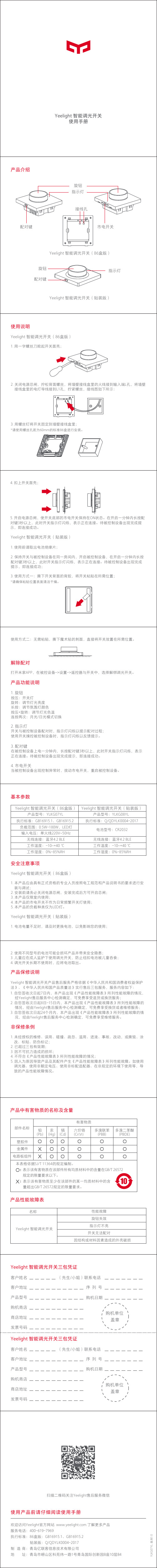
4. 扣上开关面壳;
5. 开启电源总闸,使开关底部的市电开关保持在ON状态。在开启一分钟内长按配 对键3秒以上,此时开关指示灯闪烁,表示正在连接。待被控制设备出现完成提 示,即连接成功。 Yeelight 智能调光开关(贴装版) 1. 使用前请取出电池绝缘片; 2. 保持开关与被控制设备在同一房间内,开启被控制设备,在开启一分钟内长按 配对键3秒以上,此时开关指示灯闪烁,表示正在连接。待被控制设备出现完成 提示,即连接成功; 3. 使用方式一:撕下开关背面的背胶,将开关粘贴在所需位置; *请确保粘贴位置表面清洁干燥。
情况,经由Yeelight售后服务中心检测确定,可免费享受换货或者维修服务; 3. 自您签收次日起24个月内,本产品出现《产品性能故障表》所列性能故障的情
况,经由Yeelight售后服务中心检测确定,可免费享受维修服务。
非保修条例
1. 未经授权的维修、误用、碰撞、疏忽、滥用、进液、事故、改动,或撕毁、涂 改、标贴、防伪标记;
Yeelight 智能调光开关(贴装版) 产品型号:YLKG08YL
执行标准:Q/QDYLK0004-2017
电池型号:CR2032
无线连接:蓝牙4.2 BLE 工作温度:-10~+40 ℃ 工作湿度:0%-85%RH
安全注意事项
Yeelight 智能调光开关(86盒版)
1. 本产品应由具有正式资格的专业人员按照电工规范和产品说明书的要求进行安 装与调试;
2. 安装前请务必关闭电源总闸,安装完成后方可开启总闸; 3. 本产品仅限室内使用; 4. 本产品的市电开关不作为日常频繁开关灯使用; 5. 本产品的负载种类仅为LED灯。
GrowFlux GFX-DIM 通用调光器说明书
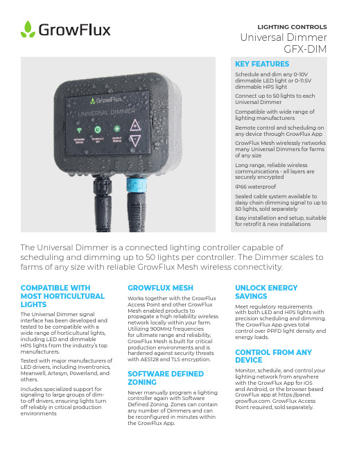
LIGHTING CONTROLSUniversal DimmerGFX-DIMKEY FEATURESSchedule and dim any 0-10Vdimmable LED light or 0-11.5Vdimmable HPS lightConnect up to 50 lights to eachUniversal DimmerCompatible with wide range oflighting manufacturersRemote control and scheduling onany device through GrowFlux AppGrowFlux Mesh wirelessly networksmany Universal Dimmers for farmsof any sizeLong range, reliable wirelesscommunications - all layers aresecurely encryptedIP66 waterproofSealed cable system available todaisy chain dimming signal to up to50 lights, sold separatelyEasy installation and setup, suitablefor retrofit & new installationsCOMPATIBLE WITHMOST HORTICULTURALLIGHTSThe Universal Dimmer signalinterface has been developed andtested to be compatible with awide range of horticultural lights,including LED and dimmableHPS lights from the industry’s topmanufacturers.Tested with major manufacturers ofLED drivers, including Inventronics,Meanwell, Artesyn, Powerland, andothers.Includes specialized support forsignaling to large groups of dim-to-off drivers, ensuring lights turnoff reliably in critical productionenvironmentsSOFTWARE DEFINEDZONINGNever manually program a lightingcontroller again with SoftwareDefined Zoning. Zones can containany number of Dimmers and canbe reconfigured in minutes withinthe GrowFlux App.GROWFLUX MESHWorks together with the GrowFluxAccess Point and other GrowFluxMesh enabled products topropagate a high reliability wirelessnetwork locally within your farm.Utilizing 900MHz frequenciesfor ultimate range and reliability,GrowFlux Mesh is built for criticalproduction environments and ishardened against security threatswith AES128 and TLS encryption.UNLOCK ENERGYSAVINGSMeet regulatory requirementswith both LED and HPS lights withprecision scheduling and dimming.The GrowFlux App gives totalcontrol over PPFD light density andenergy loads.CONTROL FROM ANYDEVICEMonitor, schedule, and control yourlighting network from anywherewith the GrowFlux App for iOSand Android, or the browser basedGrowFlux app at https://panel.. GrowFlux AccessPoint required, sold separately. The Universal Dimmer is a connected lighting controller capable of scheduling and dimming up to 50 lights per controller. The Dimmer scales to farms of any size with reliable GrowFlux Mesh wireless connectivity.BUILT FOR OPERATIONS CONTINUITYReliable through power outages, internet outages, and on-the-fly changes to devices to the network to ensure that your farm runs on schedule no matterwhat. Each device stores a schedule, and the Access Point has a battery backed clock to keep accurate date and time on site through power and internet outages.RETROFIT FRIENDLYDesigned to easily install into existing facilities to save energy and complywith evolving regulations. The Universal Dimmer family includes turnkey cabling that installs in seconds and supports the most commonly installed lights in the industry.IP66 WATERPROOFUV resistant IP66 construction with IP67connectors. Internal water resistant PTFE vent for pressure equalization keeps water out through changes in atmospheric pressure. Waterproof power cables are available separately.200 DEVICESUp to 200 Universal Dimmers can be connected to each Access Point.Each Universal Dimmer extends GrowFlux Mesh; high reliabilitywireless mesh network connection is automatically managed.ACCESS POINTSAdditional Access points can be added to a single facility for more GrowFlux Mesh devices. Accounts can have multiple access points in different time zones for multi-facility management .CONTROL ON ANY DEVICEManage your lighting systems from anywhere on any device with the GrowFlux App, available for iOS and Android, as well as the GrowFlux web app for browser and desktop control.Reconfigure your farm with ease with software defined zones. Schedules and settings are sent to all devices in a zone at once,eliminating repetitive programming tasks.Technical SpecificationsNotes:1. Some power supplies built into lighting products are biased with a positive voltage on the dimming control terminals, preventing thecontrol interface from reaching 0.00V. Electrical characteristics of some lights may prevent 0-10V line from reaching 10.00v; voltage at dimming control terminals at light is dependent on proper sizing of wiring.2. The Universal Dimmer contains specialized hardware and firmware for enhanced dimming performance for large networks of lights - upto 50 lights. Actual quantity of lights supported by the Universal Dimmer may vary by lighting manufacturer.3. Performance measured simulated loads on 0-10v interface; actual performance may vary by lighting manufacturer.4. The Universal Dimmer will extend network range of nearby devices by automatically meshing to devices at the edge of the network.10km+ (6+ mile) network range is common for networks incorporating devices spread out over large areas such as farms and cities. The Universal Dimmer will extend battery life of nearby battery powered sensors by automatically relaying messages, allowing sensors to reduce transmit power and stay asleep. Building materials such as metal, concrete, metal stud walls, and metal paneling will affect indoor through-wall range. GrowFlux Mesh typically performs with 100-300 foot range through concrete floors, CMU walls, brick walls, metal stud walls, and low-e coated windows. GrowFlux Mesh Repeaters or any GrowFlux Mesh enabled (non-battery powered) device can be used to extend wireless range for all GrowFlux Mesh enabled devices.DrawingsWhats IncludedNot Pictured:Perpetual license for Basic Cloud Controls Quickstart Guide2 conductor screw terminal break-out cable with sealed cable gland GFX-DIMA-ST24VDC Power Adapter5.5mm x 2.0mm barrel plug, NEMA 115 / North America plugUniversal DimmerGFX-DIM-10VP-1P2C-NAAccessoriesThe Universal Dimmer product family includes a sealed IP67 cable system to daisy chain dimming signal to up to 50 lights. See for latestmanufacturer compatibility.GFX-DIMTEESignal tee connectorGFX-DIMA-STScrew terminal barewire adapter with sealed cable glandGFX-ATM-DC2.0-3MIP67 sealed power cable, bare wire leads, 3 meters lengthGFX-ATM-DC2.0-FWIP67 sealed power connector. Soldering required.GFX-DIMA-RJAdapter cable with RJ connectorGFX-DIMA-FBAdapter cable for Fluence with 3-pin M16 push lock connector GFX-DIMA-FBM12Adapter cable for Fluence with 3-pin M12 threaded connector GFX-DIMA-PHAdapter cable for Philips GreenPower LED lightingGFX-DIMEXT-2MSignal extension cable, 2 metersGFX-DIMEXT-3MSignal extension cable, 3 meters GFX-DIMEXT-5MSignal extension cable, 5 metersGFX-DIMA-GEAdapter cable forGE CurrentOrdering Information Typical Part NumberGFX - DIM - AV - 1C2P - NA - KITAccessories1 2 3 4 5GFX-DIMTEE - Signal tee connector, IP67GFX-DIMA-ST - Screw terminal bare wire adapter with sealed cable gland, IP67 2022 GrowFlux, Inc. Specifications subject to change without notice. GrowFlux is a registered trademark of GrowFlux, Inc. App Store is a registered trademark of Apple, Inc. Google Play and the Google Play logo are trademarks of Google LLC. Some features require an internet connection; use of these features is subject to registration with GrowFlux, Inc. and acceptance of the GrowFlux Terms ofService, located at /tosGFX-DIMEXT-2M - Signal extension cable, 2 meters, IP67GFX-DIMA-RJ - Adapter cable with RJ connectorGFX-ATM-DC2.5-3M - Power cable, bare wire leads, 3 meters length, IP67GFX-DIMEXT-3M - Signal extension cable, 3 meters, IP67GFX-DIMEXT-5M - Signal extension cable, 5 meters, IP67GFX-DIMA-FB - Adapter cable with 3-pin M16 push lock connector, for Fluence, IP67GFX-DIMA-FBM12 - Adapter cable with 3-pin M12 threaded connector with metal locknut, for Fluence, IP67GFX-ATM-DC2.5-FW - Power connector, soldering required, IP67。
马兰士AMP-10K后级功率放大器操作说明书
后级功放操作说明书附件4特点5高音效5高性能5部件名称与功能6前面板6后面板8连接方法准备工作12扬声器12前级放大器14各种连接方法的示例15连接前级放大器16 Marantz AV 10前级放大器连接示例16双功放连接18BTL连接19连接外部控制设备20放大器控制(AMP CONTROL)插孔20 REMOTE CONTROL插孔21 FLASHER IN端子22直流控制(DC CONTROL)插孔23设置自动待机功能25连接电源线26播放基本操作28开启电源28进入待机模式28打开/关闭电平表显示屏29改变照明灯亮度30提示故障诊断31电源无法开启 / 电源关闭32不发出声音33保修和修理34附录术语解释35规格规格36索引38感谢您选购此Marantz产品。
为确保正确操作,使用该产品前请仔细阅读操作说明书。
阅读之后,请务必妥善保管以备将来参考。
附件请检查并确认本产品附带下列部件。
特点高音效016声道开关功率放大器模块开关功率放大器用于实现每声道(8Ω, 1kHz, T.H.D.: 0.05%, 双声道工作)200W的高输出。
为了确保出色的性能,所有频率下的失真都极小。
此外,频率特性几乎没有因扬声器阻抗的不同而发生变化。
本系统与带有HDAM电路的高速前级放大器相组合,可精确再现DSD和高分辨率音频源的细微差别。
0电流反馈放大器本机配备高速电流反馈放大器电路,用于精确放大来自高清音频设备(如蓝光光碟播放机)的信号。
高速电流反馈放大器也可再现天然声场。
0高音质部件电路的每个部件(包括高音质MELF电阻和电解电容)均按照确保高音质而设计。
0双层机箱0高端的机加工黄铜扬声器插孔高性能0非平衡RCA(UNBALANCED RCA)和平衡XLR(BALANCED XLR)之间切换您可以选择两种输入声道:非平衡RCA(UNBALANCED RCA)输入或平衡XLR(BALANCED XLR)输入。
0双功放/BTL连接设置功能您可以对两个声道中每个声道的功率放大器设置双功放连接和BTL连接,而无需从前级放大器再连接一根电缆。
LED调光器说明书
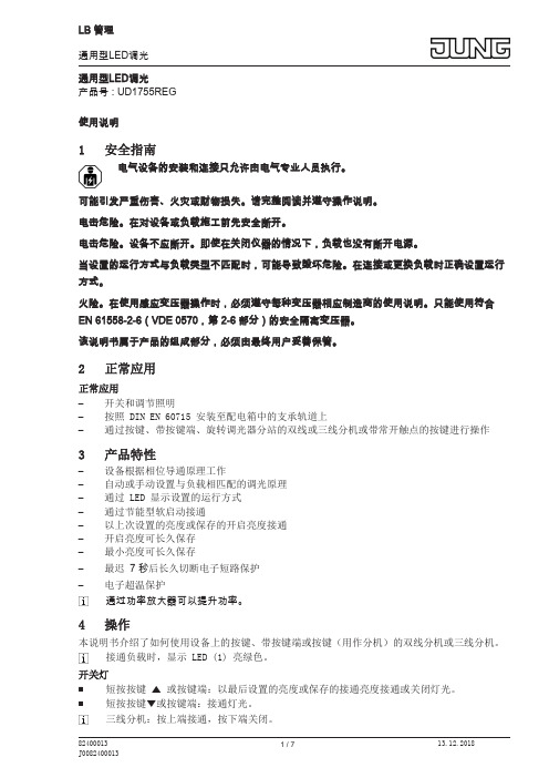
通用型LED调光产品号 : UD1755REG使用说明1安全指南电气设备的安装和连接只允许由电气专业人员执行。
可能引发严重伤害、火灾或财物损失。
请完整阅读并遵守操作说明。
电击危险。
在对设备或负载施工前先安全断开。
电击危险。
设备不应断开。
即使在关闭仪器的情况下,负载也没有断开电源。
当设置的运行方式与负载类型不匹配时,可能导致毁坏危险。
在连接或更换负载时正确设置运行方式。
火险。
在使用感应变压器操作时,必须遵守每种变压器相应制造商的使用说明。
只能使用符合EN 61558-2-6(VDE 0570,第 2-6 部分)的安全隔离变压器。
该说明书属于产品的组成部分,必须由最终用户妥善保管。
2正常应用正常应用–开关和调节照明–按照 DIN EN 60715 安装至配电箱中的支承轨道上–通过按键、带按键端、旋转调光器分站的双线或三线分机或带常开触点的按键进行操作3产品特性–设备根据相位导通原理工作–自动或手动设置与负载相匹配的调光原理–通过 LED 显示设置的运行方式–通过节能型软启动接通–以上次设置的亮度或保存的开启亮度接通–开启亮度可长久保存–最小亮度可长久保存–最迟 7 秒后长久切断电子短路保护–电子超温保护通过功率放大器可以提升功率。
4操作本说明书介绍了如何使用设备上的按键、带按键端或按键(用作分机)的双线分机或三线分机。
接通负载时,显示 LED (1) 亮绿色。
开关灯■短按按键 n 或按键端:以最后设置的亮度或保存的接通亮度接通或关闭灯光。
■短按按键o或按键端:接通灯光。
三线分机:按上端接通,按下端关闭。
设置亮度灯已开。
■长按按键 n 或按键上端。
灯光变亮至最大亮度。
■长按按键 o 或按键下端。
灯光变暗至最小亮度。
以最小亮度打开灯■长按按键 o 或按键下端。
将灯开到最小亮度。
■长按按键 n 或按键上端。
将灯开到最小亮度并且灯光变亮。
保存开启亮度发货时会将最大亮度设置为开启亮度。
■将灯调节至所需亮度。
■全方位长按按键 n 和 o 或按键端 4 秒。
Helvar调光驱动器说明书

Functional Description• DALI Type 8 compatible. One DALI address for controlling colour temperature by two output channels• DALI colour type: Colour temperature T c• Adjustable constant current output: 100 mA to 1200 mA• Current setting programmable via NFC, DALI or with external (LED-Iset) resistors • Suitable for flicker-free camera recording applications• Patented Switch-Control 2 functionality for easy-to-use intensity and colour temperature control with single push button • Full load recognition with automatic recovery, open and short circuit protection• Multipurpose terminal LED-Iset/NTC for current setting or overtemperature protection • Constant Light Output (CLO), adjustable up to 100 000 h (default disabled)• Energy consumption monitor (real time), running hour monitor (accumulative), energy management (accumulative)• Memory bank for OEM customer dataMains CharacteristicsNominal rated voltage range 220 V – 240 V, 0 / 50 – 60 Hz AC voltage range 198 VAC – 264 VAC Withstands max. 320 VAC (max. 1 hour) DC voltage range 176 VDC – 280 VDC DC starting voltage > 190 VDC Mains current at full load 0.23 - 0.26 A Frequency 0 / 50 Hz – 60 Hz Stand-by power consumption < 0.5 W THD at full power < 10 %Leakage current to earth < 0.7 mA Tested surge protection 1 kV L-N, 2 kV L-GND (IEC 61000-4-5)Tested fast transient protection 2 kV (IEC 61000-4-4)Insulation between circuits & driver caseMains circuit - SELV circuitDouble/reinforced insulation DALI circuit - SELV circuit Double/reinforced insulation Mains circuit - DALI circuit Basic insulation Output - Driver case Basic insulationMains and DALI circuit - Driver case Double/reinforced insulation Mains input - Ground inputDouble/reinforced insulationLoad Output (SELV <60 V)Output current (I out ) 100 mA – 1200 mAAccuracy ± 5 %1)Ripple < 1 %2) at ≤ 120 Hz1) At 350 - 1200 mA range. 2) Low frequency, LED load: Cree XP-G LED s.PstLM < 0.23)SVM < 0.01 3)3) At full power, measured with Cree XP-G LED modules.50 W Dimmable two channel intelligent Colour LED driver• 2-channel tunable white for human centric lighting• Wide dynamic range of colour temperatures on all dimming levels *• 0.1 % - 100 % dimming range per single channel (total range 2 % - 100 %)*• SELV output protection for safety and flexibility in luminaires• Amplitude dimming for the highest quality light output, complying with IEEE 1789 recommendation• NFC technology for wireless programming• Suitable for DC use• Ideal solution for Class I and Class II • Helvar Driver Configurator support*) See pages 2-3 for details50 W 220 – 240 V 0/ 50 –60 HzProduct code: 5775OUT(MAX) .Amplitude dimming technologyLL50iC-DA-100-1200 LED driver implements amplitude dimming technology across whole dimming range. Amplitude dimming offers the best available technology for dimming the light output in an accurate and flicker-free way to ensure high quality lighting in even the most demanding situations such as camera recording applications. Amplitude dimming technology complies with IEEE 1789-2015 recommendations of current modulation to mitigate health risks to viewers.100 %L E D c u r r e n tBrightnessD y n a m i c r a n g eDynamic range in colour temperature controlLL50iC-DA-100-1200 LED driver is ready to be used out of the box.Highest precision and color consistency in controlling combinations of different luminaire types is achieved by setting colour temperatures and lumen outputs before use with Helvar driver configurator. The configured colour temperatures of the channels should match the ones of the LED modules used. The factory default settings of cool and warm channels are 6500 K and 2700 K accordingly.After setting up the colour temperatures, the lumen output values of full dimming level (100 %) should be configured for both channels. By default, output currents are set to be equal in both channels.Total available dimming rangeset output currentD y n a m i c r a n g eSwitch-Control with tunable whiteRetractive SwitchHelvar iC drivers provide the simplest form of control in tunable white with Helvar patented single switch Switch-Control functionality. With single push button the user is able to control both the light intensity and colour temperature to the desired level. The system synchronises the light levels and CCTs every time the colour temperature is adjusted to ensure pleasant user experience and uncompromised lighting comfort. More information about the functionality can be found in Switch-Control user guide at .Wireless configurationLL50iC-DA-100-1200 LED driver is equipped with NFC wireless technology for effortless configuration of the driver via Helvar Driver Configurator Support. Helvar Driver Configurator enables easy-to-use automatic configuration of the driver parameters via NFC, without mains or DALI connection to the driver. The most popular MD-SIG qualified NFC readers (FEIG CPR30-USB & ISC.MR102-USB ) are supported giving flexibility for the operator. For further information about the usage with Helvar Driver Configura-tor, please see the user guide at Quantity of drivers per miniature circuit breaker 16 A Type CTotal continous current of the drivers and installation environment must always be considered and taken into calculations when installing drivers behind miniature circuit breaker. Example calculation of total drivers amount limited by continous current: n(I cont ) = (16 A (I nom,Ta ) / “nominal mains current with full load”) x 0.76). This calculation is an example according to recommended precautions due to multiple adjacent circuit breakers (> 9 MCBs) and installa-tion environment (T a 30 degrees); variables may vary according to the use case. Both inrush current and continous current calculations are based on ABB S200 series circuit breakers. More specific information in ABB series S200 circuit breaker documentation.NOTE! Type C MCB’s are strongly recommended to use with LED lighting. Please see more details in “MCB information” document in each driver product page in “downloads & links” section.CONTINOUS CURRENT I ½ IConnections and Mechanical DataWire size 0.5 mm 2 – 1.5 mm 2Wire type Solid core and fine-stranded Wire insulation According to EN 60598Maximum driver to LED wire length 1.5 m Weight 263 g IP rating IP20Helvar LED-Iset resistors and currents (Nominal I out(±5 % tol.*))The current can be adjusted also with normal resistors by selecting suitable resistor value (formula R [Ω] = (5 [V] / I_out [A]) * 1000). Reference resistor values can be found below order code in the table above.The LED-Iset resistor/current setting values are adjusted according to the LEDset specification. The resistor value for each required output current can thus be calculated from the formula R [Ω] = (5 [V] / I_out [A]) * 1000. Below are the available LED-Iset resistors from Helvar, pre-adjusted for the most common output currents.LL50iC-DA-100-1200 LED driver is suited for built-in usage in luminaires. In order to have safe and reliable LED driver operation, the LED luminaires will need to comply with the relevant standards and regulations (e.g. IEC/EN 60598-1). The LED luminaire shall be designed to adequately protect the LED driver from dust, moisture and pollution. The luminaire manufacturer is responsible for the correct choice and installation of the LED drivers according to the application and product datasheets. Operating conditions of the LED drivers may never exceed the specifications as per the product datasheet.Installation & operationMaximum ambient and t c temperature :• For built-in components inside luminaires, the t a ambienttemperature range is a guideline given for the optimum operating environment. However, integrator must always ensure proper thermal management (i.e. mounting base of the driver, air flow etc.) so that the t c point temperature does not exceed the t c maximum limit in any circumstance.• Reliable operation and lifetime is only guaranteed if the maximum t c point temperature is not exceeded under the conditions of use.Current setting resistorLL50iC-DA-100-1200 LED driver features a constant current output adjustable via current setting resistor.• An external resistor can be inserted in to the current settingterminal, allowing the user to adjust the LED driver output current.• When no external resistor is connected, then the LED drivers willoperate at their default lowest current level.• A standard through-hole resistor can be used for the current setting. To achieve the most accurate output current it is recommended to select a quality low tolerance resistor. Minimum diameter for resistor leg is 0.51mm.• Always connect the current setting resistor only into theterminals marked with LED-Iset on the LED driver label.• For the resistor/current values, refer to the table on page 4.LED driver earthing• LL50iC-DA-100-1200 is LED driver suitable for Class I and IIluminaires. When used inside Class I and Class II luminaires, the earth cable is recommended to be connected to improve the EMC performance of the driver, but it is not mandatory. It is the responsibility of the integrator to ensure that the assembled luminaire EMC performance complies with the latest standards. Miniature Circuit Breakers (MCB)• Type-C MCB’s with trip characteristics in according to EN 60898are recommended.• Please see more details in “MCB information” document in eachdriver product page in “downloads & links” section.Helvar Driver Configurator -supportLL50iC-D A-100-1200 LED driver is supported by Helvar D river configurator software. The LL50iC-D A-100-1200 driver supports output current setting with software, the output current of the driver can be programmed using Helvar D river Configurator, as well as OEM customer data and parameters for functions such as CLO and Tunable White behavior. Programming the driver with Helvar Driver Configurator can be done either wirelessly via NFCor then via DALI bus. Also the operation of the multifunction LED-Iset terminal usage can be changed from current setting resistor(default) to NTC overtemperature protection mp failure functionalityNo loadWhen open load is detected, driver will go to standby power consumption and remains in automatic recovery mode. In automatic recovery mode, the driver waits till load is returned and once that happens, it returns to normal operation.Short circuitWhen short circuit is detected, driver goes to automatic recoverymode and follows the same logic as described in the no load condition.OverloadWhen overload is detected, driver goes to standby mode and returnsthrough mains reset.UnderloadWhen undervoltage is detected, driver goes to standby mode and returns through mains reset.NTC triggerWhen NTC is enabled via Helvar Driver Configurator, driver follows NTC feature behaviour. D efault NTC trigger point is 8,2 kΩ, after which the driver starts to decrease the output level.Switch-Control 2Use of Switch-Control functionality• Maximum numbers of LED drivers to be connected to one switchis 60. Wire length is not restricted by the driver technology.• Ensure that all components connected to Switch-Controlcircuitry are mains rated.• More information in Switch-Control User Guide at www.helvar.com.Conformity & standardsGeneral and safety requirements EN 61347-1 Particular safety requirements for DCor AC supplied electronic control gearfor LED modulesEN 61347-2-13Additional safety requirements for AC or DC supplied electronic controlgear for emergency lighting EN 61347-2-13, Annex JThermal protection class EN 61347, C5e Mains current harmonics EN 61000-3-2 Limits for voltage fluctuations andflickerEN 61000-3-3 Radio frequency interference EN 55015 Immunity standard EN 61547 Performance requirements EN 62384 Digital addressing lighting interface:General requirements for DALI system Requirements for DALI control gear Requirements for control gear of LED modulesParticular requirements for control gear - Colour control (Dali Device Type 8)EN 62386-101 EN 62386-102 EN 62386-207EN 62386-209Recommended Practices forModulating Current in High-BrightnessLEDs for Mitigating Health Risks toViewersIEEE 1789-2015Compliant with relevant EU directivesRoHS/REACH compliantCE/UKCA and ENEC markedLabel symbolsSafety isolating control gear with short circuit protection(SELV control gear).Double insulated control gear suitable for built-in use.Thermally controlled control gear, incorporating means of protection against overheating to prevent the case temperature under any conditions of use from exceeding 120°C.D riverequipped with NFC wireless technology for effortless configuration.Helvar Intelligent Colour drivers providing DALI colour control (tunable white) functionality.。
2.4G调光LED遥控器操作说明书
技术支持万工 MOB:18665839241 MAIL:1299968664@
2.4G 智能家居遥控器
* 遥 控四组 设 备,可单 独控 制,可 群组 * 自 动识别 被 控设 备类 型 * 对 码操作 简 单可 靠 * 方 便的延 时 关灯 操作 * 4uA 的待 机 电流 * 单 键每组 可 控制 最大 250 个, 四键 1000 个 设 备
ZM2410PA08 使用说明--灯具配对操作
1. RF-2.4G 遥控手柄使用之前需要与被控制灯具进行配对,使被控制灯具允许此遥控手柄的 控制权限,防止未经配对的遥控手柄控制灯具。
群组键
第一步:打开需要配对的灯具电源,灯具开灯状态
第二步:连续短按‘设置’按键五-七次,灯具会 连续闪烁,此时关闭灯具电源,再次开启灯具时 配对完成。
小提示: 1.未加入群组的灯具,只能接受全开全关键控制,按群组键开关键不起作用。 2.未配对的灯具,不能完成群组操作。
ZM2410PA08
全开/全关
小夜灯 快速色温切换 配队与清理群组对码 上下键调节 RGB 灯颜色
RGB 灯动画播放
延时关灯 RGB 灯分段切换颜色
左右色温调节
情景模式切换 亮度加减
四个常用组别开关
.
2.4G 智能家居遥控器
* 遥 控四组 设 备,可单 独控 制,可 群组 * 自 动识别 被 控设 备类 型 * 对 码操作 简 单可 靠 * 方 便的延 时 关灯 操作 * 4uA 的待 机 电流 * 单 键每组 可 控制 最大 250 个, 四键 1000 个 设 备
使用说明--灯具群组操作 如果室内灯具较多,需要手柄进行分别开关灯或调节色温亮度等,可以将 灯具进行分组,
调光器和电源连接说明说明书

Dimmer & Power supply208Connectable length per dimmerble driverPX24606 (3A x 1ch)DALI6010 (10A x 1ch)DIM-S1L10V-0 (10A x 1ch)PWM-120-24*connectable up to 2.4A,when using 100W DC24V PSUas 60% load factor*connectable up to 3.75A,when using 150W DC24V PSUas 60% load factor*connect up to 108W as 90% load Model No.Output(W/m)Max. lengthper circuit (m)Connectable lengthper one driver (m)W (VA)Connectable lengthper one driver (m)W (VA)Connectable lengthper one driver (m)W (VA) LRE-1003-*DF-I31.2 3.3 1.856.2 2.887.4 3.4*106.1 LCEL or LCEF-0880-*-DF-I20.65 2.755.7 4.388.6 5.2*107.1 LSWK or LSXK-1008-*-DF-I-1313.16 4.356.4 6.889.18.2*107.4 LSWK or LSXK-1008-*-DF-I-88.167.1*57.611.1*89.913.3*107.7 LSWK or LSXK-1008-*-DF-I-4 4.3613.3*57.220.9*89.925.1*107.9 LNL-0980-*DF-I7.258*57.612.5*9015*108 LSM-T1000W-*-DF-I15.45 3.7*57 5.8*89.37*107.8 LFPEX15-T1000W-*-CL-*18.2 5.0 m (I), 3.5 m(O) 3.156.5 4.989.2 5.9*107.4 LFPEX20-T1000W-*-CL-*12.15 4.756.97.489.58.9*107.7 LFPEX30-T1000W-*-CL-*-99.556*579.4*89.311.3*107.4 LFPEX30-T1000W-*-CL-*-6 6.558.8*57.213.8*89.716.6*107.9 LFPEX30-T1000W-*-CL-*-4 4.5512.8*57.620*9024*108 LFPSC20-1000-*-CL-I14.25456.8 6.3*89.57.6*108 LFP15-T0900W-*-CL-*15.4 4.5 3.757 5.8*89.37*107.8 LFP20-T1000W-*-CL-*10.55 5.456.78.5*89.310.2*107.1 LFPA20-0960-*-CL-*10.45 5.5*57.28.6*89.410.3*107.1 LFTF10 or LFTXF10-T1000W-*-CL-* 3.9514.7*57.423*89.727.6*107.6 LFTF16-T1000W-*-CL-* 2.5523*57.536*9043.2*108 LRO-1142-*-DF-IW8.4 4.5 6.8*57.210.7*89.912.8*107.5 L-ELA9K2-096***-24C-P19.29357.6 4.688.3 5.6*107.5 L-ELS7K1-098***-247.7 6.97.4*5711.6*89.314*107.8 L-ELR9K2-098***-M-247.7 6.97.4*5711.6*89.314*107.8 LFU -T1000WS-*-DF-O-1515.85 3.656.9 5.688.5 6.8107.4 LFU -T1000WS-*-DF-O-121210 4.857.67.5909108 LFU -T1000WS-*-DF-O-88107.257.611.289.613.5*108 LFXK-T1000W-*-DF-O 4.81012*57.618.7*89.822.5*108Dimmer*Split into multiple circuitDimmer & Power supply | DimmerDimmer | Dimmer & Power supplyDimmer & Power supply209DALI or Touch DIM- Meets DMX512/1990- 1 output CH.,can drive 3A- With control system,can express perfect effect - Can set the DMX512 addess freely- Modularizing,can be combined with LED module neatly - Single channel constant voltage output ,10A - Meet DALI protocol IEC 62386- Dimming range from 0.1-100%- PWM digital dimming, no alter LED color rendering index - Suitable for indoor LED lighting application- Protections: Short circuit, over load, over temperature Wiring DiagramWiring DiagramMaximum wiring distance from - is 10m/20m.Please refer to manuals of each product. Please check the maximum of connectable LED length in one series referring to the catalog page of each product.When the LED total length exceeds the maximum length in series, please connect by separating into several circuit.Twist shield cable is recommended to use as a signal cable.Maximum wiring distance from - is 10m/20m.Please refer to manuals of each product. Please check the maximum of connectable LED length in one series referring to the catalog page of each product.When the LED total length exceeds the maximum length in series, please connect by separating into several circuit.Twist shield cable is recommended to use as a signal cable.0-10V DCDNX512INPUT DNX512OUTPUT For DC24V single color series PX24606series Constant Voltage - Dimmable driver (DC input) - 1ch DMX Driver 3A x 1chDimmable driver (DC input) - 1ch EUCHIPSFor DC24V single color series DALI6010Constant Voltage - Dimmable driver (DC input) - 1ch DALI Driver 10A x 1ch EUCHIPS* Please read and follow the specification and the instruction manual issued by the manufacturer of controller and driver. The specification may be subject to change without prior notice.Dimmer & Power supply2100-10V / 1-10VDC12-24VPOWERDimmer・Analog Signal driver,receive 0-10V/1-10V dimsingal.・1channel output,MAX 10A per 1ch.*Connectable 80% load=8A of LED・Over-temperature protection・Analog Signal driver,receive 1-10V dimsingal.Wiring DiagramWiring DiagramMaximum wiring distance from - is 20m.Maximum wiring distance from - is 20m.Please check the maximum of connectable LED length in one series referring to thecatalog page of each product.When the LED total length exceeds the maximum lengthin series, please connect by separating into several circuit.Twist shield cable is recommended to use as a signal cable.For DC24V single color seriesFor single color seriesDIM-S1L10V-0Walldim 103E1Constant Voltage - Dimmable driver (DC input) - 1chDimmer controller - 1ch0-10V/1-10V Driver 10A x 1ch1-10V Dimmer ControllerEUCHIPSEUCHIPSMaximum wiring distance from - is 10m/20m.Please refer to manuals of eachproduct. Please check the maximum of connectable LED length in one series referring tothe catalog page of each product.When the LED total length exceeds the maximum length in series, please connect byseparating into several circuit.Twist shield cable is recommended to use as a signal cable.* Please read and follow the specification and the instruction manual issued by the manufacturer of controller and driver. The specification may be subject to change without prior notice.Dimmer & Power supply | DimmerDimmer | Dimmer & Power supplyDimmer & Power supply211Twist shield cable is recommended to use as a signal cable.- DC 24V constant volage dimmable power supply - IP67 waterproof- 3 in 1 dimming function 0-10V, PWM, resistance Wiring DiagramFor DC24V single color series PWM-120-24Constant Voltage - Dimmable driver (AC input) - 1ch Dimmable power supply IP67MeanwellAC/L(Brown)AC/N(Blue)+V(Red)-V(Black)DIM+(Blue)DIM-(White)Dimmer & Power supply212- Support 3-in-1 dimming function(0-10V /1-10V active signal, Adjustable resistance, PWM)- Support dimming mode selectionc- Support the short circuit, over current protection and alarm functionc- Logarithmic dimming curve- Built-in CCT adjust mode, the user can adjust color temperaturewithout changing the output power- For adjusting the brightness/ color temperature of LED strip- Supply voltage of 12-15VDC- Output 2 channels 0-10V analog dimming signal- Can adjust brightness and color temperature of lamps- Show the current brightness or color grades- can be installed in compliance with DIN 49073 and 86 standard wall boxWiring DiagramWiring DiagramFor DC24V Dynamic white seriesFor Dynamic white seriesDIM-S2L8V-0Walldim 202Constant Voltage - Dimmable driver (DC input) - 2chDimmer controller - 2ch0-10V/1-10V Driver 8A, 2ch2ch Multi Function Panel ControllerEUCHIPSEUCHIPS0/1-10V SignalDC12-24VPOWER0-10V SignalDC12POWERLED DimmerConnectable length per dimmerble driver (DIM-S2L8V)ex. when using 150W PSU, 60% load factorModel No.Output(W/m)Max. lengthper circuit (m)Connectable lengthper one driver (m)W (VA)LFPTH-1000--*CL-I1158.1*89.1LTH-1000-*-DF-I31.24 2.887.4* Please read and follow the specification and the instruction manual issued by the manufacturer of controller and driver. The specification may be subject to change without prior notice.Twist shield cable is recommended to use as a signal cable.*Split into multiple circuitTwist shield cable is recommended to use as a signal cable.Dimmer & Power supply | DimmerDimmer | Dimmer & Power supplyDimmer & Power supply213- Wide input range 180 ~ 528 VAC - Constant current mode output - Metal housing with class I design- IP67 / IP65 design for indoor or outdoor installations - Function options:output adjustable via potentiometer; 3 in 1 dimming (dim-to-off); Timer dimmingWiring DiagramFor Vivoxy Graze HVGC-*-*B Constant Current - Dimmable driver (AC input) - 1ch Constant Current dimmable driver IP67MeanwellFG (Green/Yellow)AC/L(Brown)AC/N(Blue)HVGC-65DIM+(Blue)DIM-(White)-V(Black)+V(Red)* Please read and follow the specification and the instruction manual issued by the manufacturer of controller and driver. The specification may be subject to change without prior notice.Twist shield cable is recommended to use as a signal cable.Dimmer & Power supply214With thorough quality control,Luci continues to make products that customers canuse with confidenceQuality policy of Luci ORILEGA- In-house designed electric circuit and housing- Reliability test and safety test conducted by our company and third-party test laboratory- Ongoing operation test in high-temperature circumstance (60- Production process under Luci own standards and one hundred percent inspectionPSE certified range: AC100 - 242VComplied with CISPR11Ordinary LED driver used in Japan100V100V 120V242VORILEGA is PSE compliant at all voltages. Voltage range that can be used not onlyin Japan but also in many overseas countries.CISPR is an abbreviation of French of the International Special Committee on RadioInterference, and it is a standard that sets electromagnetic tolerance for equipment thatmay be affected by electromagnetic waves. Available to use in hospital and medicalinstitution as ORILEGA is in conformity to CISPR11 and CISPR15.Quiet structure conforming to JISReduced sound generation due to coil vibration during PWM dimming, maintainingoperating noise in 25 dB or less. Meets the requirements of JIS C 8115 sound level.CE mark compliance / RoHScompliant with environmental directivesAvailable to import and use in EU as ORILEGA comply with CE mark which required tobe labelled on the product complying with the laws and regulations and RoHS directivecompliant with the environmental standard in EU. In addition, ORILEGA is designedLuci ORILEGA conforms to various standardsPower SupplyPower supply | Dimmer & Power supplyDimmer & Power supply | Power supplyDimmer & Power supplyDimmer & Power supply215Luci Power Supply AC100v-242vPC isolated case, safe and durable structureRobust structure conforming to Japan indoor wiring regulations aimed at securing the safety of electrical equipment Countermeasures against discoloration and overheating*In case using LED fixture which maximum length per series is 5m.=1.25sqMaximum distanceto the terminal of LED fixture: 35 mThe distance from power supply to the terminal of LED fixture can be extended up to 35 m when the output cable is 1.25 sq mm.Structure of low heat dissipationRipple voltage occurs in DC24V output device. It may slightly affect the output effect of the LED fixtures. The lower output ripple voltage, the lower flickering occurs. Output ripple voltage of ORILEGA is 50mV which is lower than other power supply.TimetyPower supply | Dimmer & Power supplyDimmer & Power supply216LPSOLND : Non dimLPSOL -- 24 - ND -I145 : 145W 075 : 75W 030 : 30W24 : 24VLPSOL -145/075/030I : IndoorsCertification- PSE (AC100 ~242V) - CE - CCC - RoHS- IEC61000-3-2 Class C - CISPR11, CISPR15- JIS C 8115 Sound level requirement75W30W12.584side view 23512side view 25012side view 2Dimmer & Power supply | Power supplyDimmer & Power supply217Terminal block for Output side Model No. : LBX-O1Easy output side connectionOutput box with built-in terminal block Output branch (3 branch)9041.525.4side view 2side view 1top viewTerminal blockOption partsPower supply | Dimmer & Power supplyDimmer & Power supply218System configuration diagramDimmingLuci ORILEGA DC24V power supply LPSOL-*-24-ND-IExternal dimming driverInstallation Guide* Please read and follow the specification and the instruction manual issued by the manufacturer of controller and driver. The specification may be subject to change without prior notice.Dimmer & Power supply | Power supplyDimmer & Power supply219vertical orientation!- This product has a life span.- Degradation occurs inside after 8-10 years of installation even when the device looks fine from the outside.- Parts of the product degrade due to heat when using for a long period. This causes not only safety issues, but also reduces power efficiency and it is recommended to have regular maintenance and inspection. - Life cycle of the product will be shorter in high ambient temperature or in the use for a long period.- Cleaning and inspection should be performed at least once every 6 months.- Inspection by a specialist, such as a product contractor, should be performed at least once every 3 years.- If the product is used for a long time without having an inspection, there is a small possibility that it could lead to fuming, igniting, electric shock and the like. Inspection MethodsIs the output verification indicator (LED-green: located at the side of the lead-wire on output side) turned on?Are output voltage and output current in normal conditions?Is there any coloring/ fall-off/ abnormal heat build-up at wiring connection part?Is there any unusual smell, sound or heat?Are there any cracks, splits, or detached parts on any parts or joints?Cleaning MethodTurn off the power before cleaning the device.Lightly wipe this product with a soft cloth.To best clean this product, wipe dirt with a soft cloth which has been soaked in a neutral detergent diluted with water and wrung firmly. To finish off, wipe it with a damp cloth and dry it. Make sure the place of installation has enough strength to hold the weight of the device. Make sure the LED fixture meets the specification of this device.Do not perform installation/ removal work while power on. Otherwise, an electric shock may occur.Wire connection methodsInstalling the productMaintenance and Inspectioninstantly.Please ensure to connect the device to ground in order to protect from electric shock or devices from getting damaged by external noise.Power supply | Dimmer & Power supplyDimmer & Power supply220Model Product nameModel No.Rating Size noteCCC, CE Model35W Single Output Switching Power SupplyLRS-35-2485~264VACDC24V 1.5A W99 H82 D30- MEAN WELL - I/O terminal block-Protections: Short circuit / Overload / Over voltage100W Single Output Switching Power SupplyLRS-100-24DC24V 4.5A W129 H97 D30150W Single Output Switching Power SupplyLRS-150-2485~132VAC / 170~264VAC by switchDC24V 6.5A W159 H97 D30- MEAN WELL - I/O terminal block-Protections: Short circuit / Overload /Over voltage / Over temperaturCables used for connecting LED fixtures and Power supply must be a suitable type and gauge.The cable should be joined with a suitable terminal. Otherwise, the power supply will be broken. Please install appopriate envioment according to specifications.Caution: When using a long thin cable, the resistance of cable will increase. Voltage drop and heat accumulation may occur and result in brightness decreasing.Caution: When separate one cable to multiple circuits in the same gauge, the current loading are collected on the junction of the branch circuit and it will be high temprature there. Please consider the loading of the power supply (quantity of LED fixture) and review the wiring system to avoid the above problem.When connect the dimmer driver with power supply, unpredicted noise might occur. It is the characteristic of electronic devices, not a malfunction of the LED fixture.Please choose an appropriate power supply and consider a place to install. Reducing the loading factor of LED fixture mightimprove the noise from the power supply, and the noise from LED fixtures might be improved by splitting the circuit of LED fixtures into multiple.Pay attention to the electrical capacity of the load (lamp) connected to the power supply.For 15 to 150W, consumption of 70% of a full power or less by the load is typically assumed.When using dimming driver, the load factor of the LED fixtures connected to the power supply is recommended 60% or less to reduce the possibility of occurrence of noise.Example: Choosing power supply for 10pcs of Luci Power FLEX 20mm pitch Luci Power FLEX 20mm pitch 10.5W x 10pcs = 105W 105W ÷70% (load factor) = Approx. 150W Select a 150W power supply.Small noise may be emitted from the appliance and the dimmer while using the dimmer, but it is normal. Load capacity of 60% is recommended to reduce noise.Specification may be subject to change without announcement.Power supplyConnecting to power supplyPower supply selection method* Please read and follow the specification and the instruction manual issued by the manufacturer of controller and driver. The specification may be subject to change without prior notice.CE MARK CE MARK221Signature:Junko Kageyama。
2.4G调光调色温遥控器使用说明

2.4G调光调色温遥控器使用说明
按键功能
■单按“1总开机键”,所有灯具打开;长按“1总开机键”,所有灯具进入100%中性光,并且可统一调光调色温。
■单按“2总关机键”,所有灯具关闭;长按“2总关机键”,所有灯具进入小夜灯模式,即3%亮度。
■按“3、4”调亮度键,10%、100%亮度相互切换为:10等级。
单按一下,变化10%,持续按,以1%递增或递减,即松即停。
■按“4、5”调色温键,冷白光—暧白光相互切换为:10等级。
单按一下,变化10%,持续按,以1%递增或递减,即松即停。
■单按“7分组开键”,对应灯具打开;长按,对应灯具进入100%中性光;松开,再长按,进入100%冷白光;松开,再长按,进入100%暧白光,依次循环。
■单按“8分组关键”,对应灯具关闭;长按,对应灯具进入小夜灯模式。
■“9/10第二组开关键”、“11/12第二组开关键”、“13/14第二组开关键”类同以上“7/8第二组开关键”描述功能。
注:统一调光调色温,长按“1总开机键”后,再按相应调光调色温即可。
对码
第一步:打开灯具,持续通电3秒以上;
第二步:断电马上再通电,操作时间3秒之内,此时灯具渐渐变亮。
同时长按对应“分组开键”2-5秒后松开。
如灯具渐渐灭掉马上渐渐亮起,则对码成功。
第三步:若无变化对码失败,重复操作。
温馨提示:如出现遥控失灵现象,请取下遥控器电池再重新装入,即可恢复正常。
RLD灯光调光器使用与维护手册说明书

Manual for use and maintenanceLight DimmerAg/MIS/UmCn-2709-03/19 Rev 1.0P/N: 116182ChineseRLDManual for use and maintenanceRevision: 1.0 of 03/2019Product Software: Version 3.00/4.01This manual for use and maintenance is an integral part of the apparatus together with the attached technical documentation.This document is destined for the user of the apparatus: it may not be reproduced in whole or in part, committed to computer memory as a file or delivered to third parties without the prior authorization of the assembler of the system.Munters reserves the right to effect modifications to the apparatus in accordance with technical and legal developments.IndexChapter page 1INTRODUCTION ----------------------------------------------------------- 51.1Disclaimer--------------------------------------------------------------------------------------------------------------------------------------------------------------- 51.2Introduction ------------------------------------------------------------------------------------------------------------------------------------------------------------ 51.3Notes----------------------------------------------------------------------------------------------------------------------------------------------------------------------- 5 2预防措施--------------------------------------------------------------- 6 3RLD介绍---------------------------------------------------------------- 63.1产品描述--------------------------------------------------------------------------------------------------------------------------------------------------------------- 63.2软件类型--------------------------------------------------------------------------------------------------------------------------------------------------------------- 63.3缩略词及专业词汇解释---------------------------------------------------------------------------------------------------------------------------------- 73.4用户界面--------------------------------------------------------------------------------------------------------------------------------------------------------------- 7 4使用 RLD 数字调光器---------------------------------------------------- 94.1初始设置 - "选项"----------------------------------------------------------------------------------------------------------------------------------------------- 94.1.1系统参数 1 – 调光 (9)4.1.2系统参数 2 – 通道 (9)4.1.3系统参数 3– 下限 (10)4.1.4系统参数 4 – 亮度限值 (10)4.1.5系统参数5-点火脉冲 (10)4.2光亮 ---------------------------------------------------------------------------------------------------------------------------------------------------------------------- 104.3手动调光------------------------------------------------------------------------------------------------------------------------------------------------------------- 104.4自动调光------------------------------------------------------------------------------------------------------------------------------------------------------------- 114.5冷启动 ----------------------------------------------------------------------------------------------------------------------------------------------------------------- 11 5配置------------------------------------------------------------------ 125.1环境保护------------------------------------------------------------------------------------------------------------------------------------------------------------- 12 6安装------------------------------------------------------------------ 136.1RLD布线图 ---------------------------------------------------------------------------------------------------------------------------------------------------------- 136.2通道级别设置--------------------------------------------------------------------------------------------------------------------------------------------------- 156.2.1利用模拟输出卡 (15)6.2.2经通讯卡连接 (17)7问题与解决方案-------------------------------------------------------- 181Introduction1.1DisclaimerMunters reserves the right to make alterations to specifications, quantities, dimensions etc. for production or other reasons, subsequent to publication. The information contained herein has been prepared by qualified experts within Munters. While we believe the information is accurate and complete, we make no warranty or representation for any particular purposes. The information is offered in good faith and with the understanding that any use of the units or accessories in breach of the directions and warnings in this document is at the sole discretion and risk of the user.1.2IntroductionCongratulations on your excellent choice of purchasing an RLD!In order to realize the full benefit from this product it is important that it is installed, commissioned and operated correctly. Before installation or using the fan, this manual should be studied carefully. It is also recommended that it is kept safely for future reference. The manual is intended as a reference for installation, commissioning and day-to-day operation of the Munters Controllers.1.3NotesDate of release: July 2010Munters cannot guarantee to inform users about the changes or to distribute new manuals to them.All rights reserved. No part of this manual may be reproduced in any manner whatsoever without the expressed written permission of Munters. The contents of this manual are subject to change without notice.2预防措施•必将温度传感器线屏蔽接地。
LT-0610P智能调光控制器用户手册说明书

LT-0610P智能调光控制器用户手册北京星光莱特电子有限公司BEIJING STARLIGHT ELECTRONICS CO.,LTD北京市大兴区西红门镇金盛大街2号院18号楼3层100076 交货-拆包安全知识操作电缆注意事项主要功能产品特性产品安装和要求控制器的安装环境要求控制器的安装尺寸要求控制器的固定和安装电源线的连接主供电网络形式供电电缆接线要求接线端口星形系统单相变换输出连接控制信号的连接方式及走线要求协议简介:DMX512/1990协议简介:LT-NET控制电缆连接标准工作状态及方式的选择各类检测、保护及恢复方法交货-拆包当您收到LIGHTSPACE®的产品时,请确认包装尚未拆卸,并仔细检查设备是否完好;所有设备是经严格检验,并确认完好才允许出厂的;如果发现设备有任何损坏,请及时联系相关人员,并记录在案。
核对您收到的产品和系列产品规格与清单上的是否一致;检查您收到的设备的型号、数量与交付单上的是否一致;一旦发现出错,立即与发货方联系,说明情况直到收到满意答复。
确认无误后,把产品放回包装,置于符合存储条件的位置,等待最后的安装。
安全知识LT-0610P是专业型的全数字调光器,符合欧洲安全标准:EN60439,EN60950,它属于Ⅰ类设备,按EN 60439设计生产,按当地规格强制安全接地。
为防止任何触电事故,请不要打开外壳和防护措施,正常操作无需了解设备内部情况。
如设备有损坏必须由专业人员检查和维修,在检查和维修之前请确认电源已切断。
警告!!!内有致命电压!注意您的安全!安装调试和维修服务应由专业人员操作!任何人员使用前,务必仔细阅读此手册,并按照要求使用。
操作电缆注意事项供电电缆和连接器是设备安全的重要组成部分。
⚫电缆供电端必须有主断路器、保险器等,用于切断电源,并且不能触碰到电缆;⚫安装和检查时,要确保电缆和连接器无任何损坏;⚫电缆和信号线不能置于一处。
主要功能⚫6个调光通道输出,每个通道10A⚫每个通道有一个10A小型断路器和一个旁路直通开关⚫应用于分布式智能灯光控制系统⚫双接口输入,可接收LT-NET信号和DMX-512信号⚫系统输出一组12V直流电压,供给控制系统使用⚫三相电源LED指示及一个通讯指示LED⚫可预置场景128个⚫可分区域128个⚫渐变时间:1~100秒⚫采用大功率可控硅及快速电磁开关,降低因短路事故烧毁可控硅的概率⚫每个通道有一个专业滤波器上升斜率为120uS,减少灯丝噪音⚫自动限压功能使输出电压限制在230V以内,延长灯泡的使用寿命⚫可以控制白炽灯泡、卤钨灯泡、经变压器的低电压灯泡产品特性电子控制:全数字、微处理器控制额定功率:调光器连续工作额定负荷:6 x 2 kWLT-0610P 最大整机负荷为12 kW工作温度范围:0℃到40℃,25℃时相对湿度不大于90%,大气压力小于106kP供电系统:3NPE 400V 50Hz (TN-S 系统, 中性线直接连接到地,相和中性线间230V) 不允许减少N线线径可以单相工作(单相保护)供电电压范围:198 V 到264 V (230 V±14 %)额定供电电流:星型3-相3N~ with PE 供给: 230V 时每相20 A单相供给:在230 V 时60 A调光器保护:MCB 微型断路器(最大分断能力6kA)输入控制:双接口输入,DMX 和LT-NET信号可同时工作,遵从大者优先原则DMX控制信号:正确的DMX 信息——通讯LED指示灯连续闪动LT-NET控制信号:正确的LT-NET信息——通讯LED指示灯红绿交替变化控制端输出电压:12V /0.2A地址:调光器的首地址可通过手持编程器设定(设定时应将机内拨码开关拨下)前面板指示:每个通道电源连接是否正常(MCB是否跳开)DMX512 或LT-NET 控制信号是否正常(通讯LED指示灯显示)电源故障信息(电源LED指示灯显示)调光器测试功能:当按下紧急直通按钮时,可使用机内的微调电位器0~100%调整6路通道的输出亮度旁路直通开关:当功能模块出现故障,可按下对应回路的旁路直通开关响应时间:DMX≤30ms调光器精度:1024 级功率半导体器件:反并联可控硅每路调光器最小负荷:≥60W输出电压的DC成份:在额定负载范围内低于1V负载类型:白炽灯泡、卤钨灯泡、经变压器的低电压灯泡供电电缆颜色:相线L1,L2,L3棕色或黑色中性线N蓝色地线PE黄绿色电磁兼容标准:EN55103-1:1996EN55103-2:1996安全标准:EN60439,EN60950保护:⑴由MCB (6k A 分断能力)提供每路保护,在规定条件下系统安全运行;⑵电源端子进线线径:刚性最大25 mm2、柔性最大16 mm2;⑶负载端子出线线径:刚性最大6mm2、柔性最大4 mm2;⑷从机框的顶部敲落孔或后面板中的进线方孔进电缆;⑸控制信号的接线端在底部敲落孔进线。
萤石 智能照明-调光控制器 CS-HAL-LC1 使用说明书

萤石LC1用户指南使用产品前请仔细阅读用户指南目录装箱清单 ������������������������������������������������������������3外观介绍 ������������������������������������������������������������4配置流程概览 �����������������������������������������������������5下载“萤石云视频” ������������������������������������������5安装设备 ������������������������������������������������������������6添加至“萤石云视频” ���������������������������������������7参数信息 ������������������������������������������������������������9售后服务支持 ���������������������������������������������������10上门安装服务 �����������������������������������������������������������������������������10声明 ������������������������������������������������������������������������������������������10版权声明 ����������������������������������������������������������11装箱清单使用“萤石云视频”客户端扫描该二维码可快速添加设备使用其它工具(例如微信、浏览器等)扫描该二维码可查看详细用户指南设备 x1用户指南 x1文中所有图片仅供参考,请以实物为准。
SOC-2100S 调光器高压切换柜 用户手册说明书
SOC-2100S 调光器高压切换柜用户手册大连宗益科技发展有限公司SOC-2100S 调光器高压切换柜用户手册版本:中文 1.1时间:2017年10月编写:张灵复核:高峰版权所有○C大连宗益科技发展有限公司感谢您选购了我公司研制生产的调光器系列产品,为使您的设备工作在最佳状态,请详细阅读本手册,并保存以供参考。
请遵守本手册中的操作规程及注意事项。
本手册介绍了SOC-2100S型高压切换柜的性能,及如何将其与我公司生产的CCR-2100型和CCR-2100S型调光器组成切换系统。
若您将以上高压切换柜与其他厂家的设备组成切换系统,请与我公司联系,以获得详尽、完善的配置方案。
您可以通过以下方式联系我们:大连宗益科技发展有限公司地址:大连市高新园区凌秀路60A邮编:116023电话:**************************传真:*************E-mail:*****************SOC-2100S 调光器高压切换柜目录系统配置7设备安装8电气连接9人机界面系统简介12人机界面操作12报警显示19运行测试方法22自动切换26手动切换28安全注意事项●操作该设备的人员必须经过专业培训。
●该设备运行时,柜内具有高压,请勿打开前、后门。
●回路检修时,请务必断开切换柜及调光器的供电电源。
●若切换组内调光器发生故障,请在助航灯光使用结束后进行维修。
●发生自动切换后,严禁进行手动切换,直到故障调光器维修完毕并且灯光使用结束后再进行复位操作。
●若调光器故障时切换系统不能自动切换,可进行手动切换使备调光器投入运行。
●请定期检查真空继电器是否有破损,如有损坏应及时更换。
●切换柜必须保持可靠接地。
●请注意紧固切换柜前、后接线板上接线端子螺丝。
●请注意保持柜体内外清洁,注意防尘和防潮。
安全提示设备运行时,在切换柜内灯光回路电缆接线端有高压,请注意安全!产品主要特点●调光器高压切换系统用于调光器的热备份,在主调光器故障时能够快速将该调光器所带灯光负载自动或手动切换到备调光器,保障灯光回路正常运行。
灯光控制台说明书
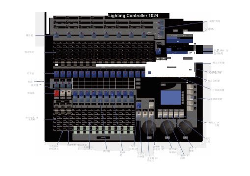
属性^页纯 功罪瓢属性键 帧过指杆 一灯具定位键〜充缎选灯链灯耳谊 、灯具翻页键黑场饿 菜源速揉健确定[更索材槌Lighting Controller 1024w HH离开或 取消诩预苦推杆 的思调无菜单 下翻桃多多的 向后继续控台鹿L 调光推杆 名景的 哲杪键、编程区 济空键重演 -------- 拥页键7^ 重:演 健连接 多址设菜单 上翻键重演推杆 的总渭光重演推杆Ik. vr Clifira△tup:九 k :辱-LE 1%btt 绮 air« T*Mr■■,■K3H2■ Fp~尸 IT 1MUlrfT预置.推杆 功能切换犍hif LKk#.^v^aaCHF-x'b-vLM L■■f:灯具菜单键客景的 向前继续 键一、灯光配接1.电脑摇头灯、帕灯需用灯库配接。
配接时所有推子归(0),注意:预置推杆 灯具配接如下:配接灯具(红灯亮)。
配接电脑灯一^配接摇头灯一光束灯-230W-DMX 咽(转盘V )修改地址码一选择灯具页与未配接通道连接。
।一 配接帕灯-LEDPAR7-DMX 000 (转盘V )修改地址码一选择灯 具页与未配接通道连接。
配接天排灯—LEDPAR8-DMX 000 (转盘V )修改地址码一选择 灯具页与未配接通道连接。
J 配接常规灯—DMXMER —DMX 000 (转盘V )修改地址码一选择灯P 灯 (7通道) 灯具页0:面光 灯 ①1-7灯架 ②观众8-14 ③观众 15-21④主屏 22-28⑤主屏29-35⑥左屏36-42⑦右屏43-49(图表1)天排灯 (7通道) 灯具页1 灯架⑧1-8 50-56(图表2)电脑灯(16通道) 灯具页0灯架⑨主屏 57-72 ⑩主屏 73-88 ⑪左屏 89-104⑫右屏105-120台面⑬地面121-136⑭地面137-152(图 3表 3)蜘蛛灯 (18通道)台面⑮自动153-170蜘蛛灯通道 M1轴 M2轴X 轴左右旋转 3B调光 6 B 调光 12 B18通道程序旋转 4 B 旋转 12 A频闪 2 B 频闪 13 A红色 8 B 红色 14 A绿色 11 B 绿色 15 A蓝色 1 A 蓝色 13 B 白色11 A白色14 B(图 三表4)二、数据备份与读取(插入U 盘,U 盘格式:FAT32)备份:设置一优盘管理一保存数据A 一(转盘V 修改名称)一确认 读取:设置一优盘管理一读取数据B 一确认 三、帕灯操作流程1.帕灯通道:1-7 (见图表1)总控(推到10)一选择通道一定位(点炮)一属性页(选择功能)一转盘调光,绿灯亮具页与未配接通道连接。