霍尼韦尔CARE控制资料
care中文手册
word格式-可编辑-感谢下载支持目录1、定购与注册2、启动CARE3、CARE 概述4、CARE 界面5、基本操作6、工程定义与管理7、设备定义与管理8、控制器定义、捆绑设备与管理9、设备原理图10、控制策略11、开关逻辑12、文本编辑器13、创建时间程序14、端子分配功能15、文件管理16、LonWorks 网络设计17、Excel 10 应用程序18、XLINK 控制器19、OLink 控制器20、OPS 控制器21、在线调试-XL Online22、点属性表23、工程单位24、错误信息第一章订购与注册CARE4.01.00 可以从客户服务中心(CSC)/GE51 或者从下面网址下载这个版本是未注册的限制功能的演示版本(评估版本)。
为了进一步使用CARE 的完整功能,用户需要为你的演示版本申请一个授权。
这个授权可以通过运行CARE 的同时,连接霍尼韦尔授权服务中心(e.ge51.honeywell.de)完成。
授权的过程基于3 个方面:➢订购号:打印在CARE 光盘的标签上➢参考码:在CARE 安装时自动在硬盘上创建➢授权码:由霍尼韦尔授权服务器自动创建用户拥有一个授权后,可以免费获得另一台电脑的授权(如笔记本或台式机)。
如果软件有新版本,已获得授权的用户能够选择需要的新功能进行版本升级。
一个已经报失的授权码一年后可以用新的代替。
另外,用户也可以将CARE 的授权转给其他的计算机。
授权包括以下两个步骤:订购注册重要提示:CARE 只能通过使用霍尼韦尔订购系统的分公司或霍尼韦尔的代理商订购。
一、1 CARE 注册界面介绍步骤:1、运行CARE,进入主窗口2、菜单栏帮助(Help)->注册(Registration)3、进入注册对话框,查看注册授权信息。
Reference Code:安装CARE 的机器码。
User ID:你的授权注册用户名。
Expiration:使用期限。
Features:获得授权的功能。
十一 CARE中VAV2控制器工程与调试

5)
Control Parameters
-
(
)
• • •
< < < <
<
< <
<
6) Input
PID
Copyright @ 2008-2009 Honeywell. All rights reserved.
Page 14 of 31
CARE
VAV2
ECC AP Technical Assistance Center
Page 16 of 31
CARE
VAV2
ECC AP Technical Assistance Center
5. VAV2
5.1 VAV2
1) 2)
CARE
Plug-Ins (
/
)
“VAV2 OEM 3) 4) Plugin Configuration
” VAV2 Configure ( / )
Project Setting
3)
Plugin
VAV2 Configure
4)
Configuration
Copyright @ 2008-2009 Honeywell. All rights reserved.
Page 13 of 31
CARE
VAV2
ECC AP Technical Assistance Center
Copyright @ 2008-2009 Honeywell. All rights reserved.
Page 3 of 31
CARE
VAV2
ECC AP Technical Assistance Center
HoneywellAccessControl(HAS)门禁系统精选产品参数手册

HoneywellAccessControl(HAS)门禁系统精选产品参数手册霍尼韦尔门禁产品精选手册原北方电脑系列1门禁管理软件系统............................................................. ....................................................41.1WinPak2 005............................................................ ......................................................41.2WinPa kPro2005....................................................... .. (6)2门禁控制器............................................................. . (10)2.1.1主控制模块(PRO22IC).................................................... ....................................102.1.2PRO22双读卡器模块(PRO22R2).................................................... ...................122.1.3PRO2200单读卡器模块(PRO22R1).................................................... ...............142.1.4PRO2200继电器输出模块(PRO22OUT)................................................... .........152.1.5PRO2200报警输入模块(PRO22IN).................................................... ................162.1.6PRO2200RS232/485通信协议转换器(PRO22CVT1).........................................172.1.7PRO2 200以太网通讯卡(PRO22EN)...................................................... .. (17)2.2NS2+两门门禁控制器............................................................. (183)Honeywell门禁系统系列前端配件............................................................. .........................193.1感应智能卡读卡器(OmniCla系列)........................................................... ..............193.2感应智能卡读卡器(JT-MCR系列)........................................................... ..................223.3ID感应读卡器(OmniPro某系列)........................................................... (234)附录............................................................. ............................................................... .........244.2主要设备、器材的选择和配置原则............................................................. . (24)4.1.1主控模块的配置............................................................. .....................................244.1.2读卡器模块的配置............................................................. ..................................244.1.3读卡器的配置............................................................. ........................................254.1.4电锁的配置............................................................. ............................................254.2系统调试............................................................. . (25)4.2.1系统阻抗测试.....................................................................................................264.2.2阻抗测量............................................................. ................................................264.2.3绝缘阻抗测量............................................................. .........................................264.2.4系统接地电阻测量............................................................. ...............................264.2.5各种模块(主控模块及扩展模块等)通电调试..................................................264.2.6前端设备调试............................................................. .......................................274.2.7系统联调............................................................. ..............................................274.2.8系统试运行。
霍尼韦尔楼宇自控系统介绍-控制原理图说明

28
高压进线
电 流
智能电表1630
电压 电压
变配电系统
低压进线
电 流
配电系统
配电系统
配电系统
配电系统
内部组网
智能电表1630 Modbus
SCADA
OPC Server
LAN
A53
OPC Client
SymmetrE
Honeywell Confidential
29
SymmetrE
变配电系统 高压母联状态 高压进线状态 高压进线故障 高压主进有功功率 高压主进功率因数 高压主进电流 高压主进电压 高压主进频率 低压母联状态 低压进线状态 低压进线故障报警 低压主进有功功率 低压主进功率因数 低压主进电流 低压主进电压 低压主进频率 变压器高温报警
新风机组
AI AO DI DO 1
1 1 1 2
1 1
21
1
1
1
5
3
8
Field Device
H7050B1018 CN6120A1002 V5011P1038
ML7420 T6950A1000
DPS400
选择DDC XL50
新风机组
Honeywell Confidential
9
空调机组
Honeywell Confidential
Honeywell Confidential
18
潜污泵 水泵启停 运行状态 故障报警 手自动状态 报警水位 启泵水位 停泵水位 合计
生活排水系统
AI AO DI DO 现场设备
2
2
2
2
1
MAC-3-5M
1
MAC-3-5M
udc2300 霍尼韦尔通用控制器说明书
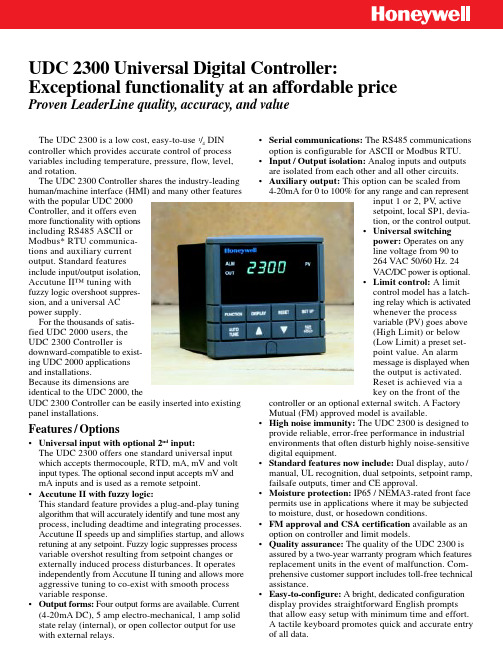
UDC 2300 Universal Digital Controller:Exceptional functionality at an affordable priceProven LeaderLine quality, accuracy, and valueThe UDC 2300 is a low cost, easy-to-use 1/4 DIN controller which provides accurate control of process variables including temperature, pressure, flow, level,and rotation.The UDC 2300 Controller shares the industry-leading human/machine interface (HMI) and many other features with the popular UDC 2000Controller, and it offers even more functionality with options including RS485 ASCII or Modbus* RTU communica-tions and auxiliary current output. Standard features include input/output isolation,Accutune II™ tuning with fuzzy logic overshoot suppres-sion, and a universal AC power supply.For the thousands of satis-fied UDC 2000 users, the UDC 2300 Controller isdownward-compatible to exist-ing UDC 2000 applications and installations.Because its dimensions are identical to the UDC 2000, theUDC 2300 Controller can be easily inserted into existing panel installations.Features / Options•Universal input with optional 2nd input:The UDC 2300 offers one standard universal input which accepts thermocouple, RTD, mA, mV and volt input types. The optional second input accepts mV and mA inputs and is used as a remote setpoint.•Accutune II with fuzzy logic:This standard feature provides a plug-and-play tuning algorithm that will accurately identify and tune most any process, including deadtime and integrating processes.Accutune II speeds up and simplifies startup, and allows retuning at any setpoint. Fuzzy logic suppresses process variable overshot resulting from setpoint changes or externally induced process disturbances. It operates independently from Accutune II tuning and allows more aggressive tuning to co-exist with smooth process variable response.•Output forms: Four output forms are available. Current (4-20mA DC), 5 amp electro-mechanical, 1 amp solid state relay (internal), or open collector output for usewith external relays.•Serial communications: The RS485 communications option is configurable for ASCII or Modbus RTU.•Input / Output isolation: Analog inputs and outputs are isolated from each other and all other circuits.•Auxiliary output: This option can be scaled from 4-20mA for 0 to 100% for any range and can representinput 1 or 2, PV , active setpoint, local SP1, devia-tion, or the control output.•Universal switching power: Operates on any line voltage from 90 to 264 VAC 50/60 Hz. 24VAC/DC power is optional.•Limit control: A limit control model has a latch-ing relay which is activated whenever the process variable (PV) goes above (High Limit) or below (Low Limit) a preset set-point value. An alarm message is displayed when the output is activated.Reset is achieved via a key on the front of thecontroller or an optional external switch. A Factory Mutual (FM) approved model is available.•High noise immunity: The UDC 2300 is designed to provide reliable, error-free performance in industrial environments that often disturb highly noise-sensitive digital equipment.•Standard features now include: Dual display, auto /manual, UL recognition, dual setpoints, setpoint ramp,failsafe outputs, timer and CE approval.•Moisture protection: IP65 / NEMA3-rated front face permits use in applications where it may be subjected to moisture, dust, or hosedown conditions.•FM approval and CSA certification available as an option on controller and limit models.•Quality assurance: The quality of the UDC 2300 is assured by a two-year warranty program which features replacement units in the event of malfunction. Com-prehensive customer support includes toll-free technical assistance.•Easy-to-configure: A bright, dedicated configuration display provides straightforward English prompts that allow easy setup with minimum time and effort.A tactile keyboard promotes quick and accurate entry of all data.Condensed Specifications51-52-58-16 (5M) 1/99•Highly secure: Non-volatile memory assures data integrity during loss of power. Four configurable security levels plus a four-character code prevent accidental or unauthorized changes to the process.Industrial Automation and ControlHoneywell Inc.U.S.A.: Honeywell Industrial Automation and Control, 16404 North Black Canyon Hwy., Phoenix, AZ 85053Canada: The Honeywell Centre, 155 Gordon Baker Rd., North York, Ontario M2H 3N7Latin America: Honeywell Inc., 480 Sawgrass Corporate Parkway, Suite 200, Sunrise, Florida 33325Japan: Industrial Operations Tokyo, 4-28-1 Nishi-Rokugo Ohtu-ku, Tokyo 144, JapanAsia: Honeywell Asia Pacific Inc., 101 Thomson Road, #06-00 United Square, Singapore 307591, Republic of Singapore Pacific Division: Honeywell Pty Ltd., 5 Thomas Holt Drive, North Ryde NSW Australia 2113Northern Europe and Southern Africa: Honeywell Ltd., Honeywell House, Arlington Business Park, Bracknell, RG 12 1EB, U.K.Central Europe: Honeywell A.G., Kaiserleistraße 39, D-63067 Offenbach, GermanyWestern and Southern Europe: Honeywell S.A., Avenue du Bourget 1, B-1140 Brussels, Belgium Eastern Europe: Honeywell Praha, s.r.o., Budejovicka 1, 140 00 Prague 4, Czech RepublicMiddle East: Honeywell Middle East Ltd., Khalifa Street, Sheikh Faisal Building, Abu Dhabi, U.A.E.©Honeywell Inc. Printed in U.S.A. Recycled Paper•Additional Options include:–Two alarms or a second control output and one alarm –Remote setpoint via Input 2–Digital input (mutually exclusive with auxiliary output and communications)–Setpoint program (six ramps + six soaks)–Customer ID tag –Rear terminal coverThe reliability, accuracy and quality of Honeywell’s industry-proven LeaderLine ® family of controllers are sec-ond to none and offer the best total value of ownership.The UDC 2300 is backed by a two-year warranty and, as with all Honeywell industrial products, is supported by the largest service network in the industry.Honeywell provides a complete line of temperaturesensors including thermocouples, RTDs, and non-contact sensors that are compatible with the UDC 2300 andother industrial control products.*Modbus is a trademark of Modicon.。
HONEYWELL自控教程

H O N E Y W E L L自控教程 Document number:WTWYT-WYWY-BTGTT-YTTYU-2018GT目录目录 (2)1、BAS系统设备检测及调试步骤(STAM)概述 (1)2、DDC 加电检测 (2)Excel 50加电检测步骤 (2)XL50 DDC测试报告 (5)Excel 100 加电检测步骤 (6)XL100 DDC测试报告 (9)Excel 500 加电检测步骤 (10)XL500 DDC-测试报告 (13)3. BA系统监控设备现场调试方案 (14)空调机组的调试方案 (14)空调机组“关”状态下的目视及功能测试 (14)空调机组送风风机启停检查 (14)空调机组温度控制 (15)空调机组过滤器报警 (15)连锁功能测试 (15)机组间连锁功能的测试 (15)最终调整与标定 (15)固定和手动模式的复位 (16)、新风机组测试方案 (16)新风机组“关”状态下的目视及功能测试 (16)新风机组送风风机启停检查 (16)新风机组温度控制 (17)新风机组防冻报警 (17)连锁功能测试 (17)最终调整与标定 (17)固定和手动模式的复位 (18)FCU末端的调试方案 (18)FCU现场调试方案 (18)FCU 调试方案 (18)FCU风机启停检查 (19)固定和手动模式的复位 (19)送、排风机的调试方案 (20)送、排风机“关”状态下的目视及功能测试 (20)送、排风机机启停检查 (20)固定和手动模式的复位 (20)给水系统调试方案 (20)给水水泵“关”状态下的目视及功能测试 (20)水泵启停检查 (21)液位变送器校准 (21)联动功能测试 (21)固定和手动模式的复位 (21)排水系统调试方案 (21)排污泵“关”状态下的目视及功能测试 (21)水泵启停检查 (22)水位开关的测试 (22)联动功能测试 (22)固定和手动模式的复位 (22)照明系统调试方案 (22)照明回路“关”状态下的目视及功能测试 (22)照明回路开关检查 (22)固定和手动模式的复位 (23)冷热站调试方案 (23)直燃机房被控设备目视及功能测试 (23)空调补水系统联动功能测试: (23)1、BAS系统设备检测及调试步骤(STAM)概述本手册所述检测与调试步骤是按照中铁一局BAS系统设计要求进行编制的.编制本手册的目的是:A.在实际调试工作开始之前准确的制定调试计划,并使用户能够了解我们的调试步骤.B.指导调试人员进行系统调试..C.按调试步骤制定及生成准确的调试记录和报告.编制:Date:Approved By:Date:2、DDC 加电检测Excel 50加电检测步骤供电之前:1)对DDC盘内所有电缆和端子排进行目视检查,以修正显性的损坏或不正确安装。
霍尼韦尔DDC编程软件(CARE)简介

二、CARE中的基本概念
1.Controller——控制器
就是DDC控制器,如Excel 50,80,100,500,600以及Excel Smart等。 2.Plants——设备
CARE的所有功能都是基于设备的。
一个设备是一个被控系统。例如:一个设备可以是空 气处理机组(air handle),锅炉(boiler)或是制冷设备 (chiller)。
如果要编辑设计CARE的应用程序(设备原理图、 控制策略、开关逻辑、时间程序),对应的应用程序 也会在信息与编辑面板中显示出来。
四、 CARE主要应用程序
CARE提供4个主要的应用程序来设计控制 程序:
设备原理图 控制策略 开关逻辑 时间程序
另外,参考码、授权用户名、订购号等信息也是工程 的一部分。
4.Plant Schematics——设备原理图
每个设备创建一个原理图。
一个设备原理图是若干段的一个组合,这 一个控制系统如锅炉、泵以及其他设 备的组成元件。元件包括传感器、状态点、阀门等。 CARE提供了一个宏库,它有预定义的元件和设备。
5.Control Strategy——控制策略
建立了一个原理图之后,就可以创建控 制策略,使得控制器具有处理系统的智能。
控制策略根据具体情况,数据计算, 或时间表来做出决策,控制可由控制器的模拟 点、数字点或软件点完成。
CARE提供了标准控制算法如PID、最小 值、最大值、平均值等。
6.Switching Logic —— 开关逻辑
2、网络结构分支树:
网络树提供一 个关于工程的总线系 统和网络结构的总的 轮廓,这有助于管理、 组织的工程中用到的 网络组件(C-Bus控 制器、LON装置、LON 对象等)。
楼宇自控系统应用手册(霍尼韦尔)

并使用户能够及时掌握各种情况。 • 设计与开发均符合 ISO 9001 国际质量标准
SymmetrE是什么 SymmetrE 是一个具有高度可配置性的设备管理系统,它提供了一种有效而又可靠的方法,能够确保用户的舒适度及楼宇和设备 的高效运行。 SymmetrE 是一个智能楼宇管理系统,它为存取信息及对一个或多个楼宇的控制需求提供了一套完整的解决方案。
LonWorks BUS
Router Modem
XPC 500-PCI Card
Excel 50
Honeywell C-Bus Devices
3nd Party Lon Devices
Plant Contro Ilers
Excel 500
Smart Excel 500
CVAHU XL10
FCU XL10
领导历史的潮流
Honeywell 公司是在 1999 年 6 月通过 Allied Signal(联信)公司
和 Honeywell(霍尼韦尔)公司合并后重新组成的。合并的两家公司都 具有悠久的历史。
Allied Signal 公司的历史可追溯到本世纪初。Allied 化学品和燃料 公司成立于 1920 年,它是由五家美国化学品公司组成的,这些公司的 历史都可追溯到十九世纪后期。1985 年,Allied 公司与 Signal 公司合并。 Allied Signal(联信)公司成为一家在技术和制造领域领导潮流的高科技 公司,其股票是 Dow Jones(道 • 琼斯)30 种主要工业股票之一。
Distributed
I/O
Smart I/O
HONEYWELL CARE培训资料

39
HONEYWELL - CONFIDENTIAL
File Number
修改数据点(Modify Datapoints)
方法B:Modify Datapoints in Grid Display 1.从Logic Plant tree 选择设备Plant 2.适合修改一批(多个)数值
40
HONEYWELL - CONFIDENTIAL
HONEYWELL - CONFIDENTIAL
File Number
CARE 概念 1. Plants---设备
一个设备是一个被控系统。例如:空调机,锅炉,冷冻机 CARE的所有功能是基于设备的 一个DDC可以包含一个或多个设备,取决于DDC点的数量
2.
Points--- 点
•
CARE 中常用六种类型的点:
File Number
CARE环境
20
HONEYWELL - CONFIDENTIAL
File Number
CARE环境
Q&A?
21
HONEYWELL - CONFIDENTIAL
File Number
Project 的建立步骤
• • • • • • • • • • • • • • • 创建工程/项目 创建控制器 创建设备 创建设备原理图 修改控制点 手动分配控制器端子 设计控制策略 设计开关逻辑 创建时间程序 设计、配置C-Bus网络 在网络树中创建、布置控制器 连接控制器 编译控制器 下载到控制器 配置OPEN-LON装置
9
HONEYWELL - CONFIDENTIAL
File Number
CARE 概念 CARE 系统模型
10
霍尼韦尔 S10010 S20010 A使用说明书

® U.S. Registered TrademarkEN0B-0463GE51 R0418Copyright © 2018 Honeywell Inc. • All rights reservedS10010 / S20010SPRING RETURN DIRECT-COUPLED DAMPER ACTUATORS10/20 Nm (88/177 lb-in) FOR MODULATING AND FLOATING CONTROLPRODUCT DATAGENERALThese direct-coupled damper actuators provide modulating / floating control for: ∙ air dampers, ∙ VAV units, ∙ air handlers, ∙ ventilation flaps, ∙ louvers, and∙ reliable control for air damper applications with up to1.5 m 2 / 16 sq.ft (10 Nm / 88 lb-in) or 4.6 m 2 / 50 sq.ft. (20 Nm / 177 lb-in) (seal-less dampers; air friction-dependent).FEATURES∙ Self-centering shaft adapter ∙ Removable access cover∙ Mechanical end limits (non-adjustable)∙Rotation direction selectable by choice of mounting orientation∙ Mountable in any orientation (IP54 only whenmounted on a horizontal shaft with access cover below the shaft)∙ Mechanical position indicatorSPECIFICATIONSSupply voltage S10010 / S20010 24 VAC ±20% / 24 VDC, 50/60 Hz Nominal voltage S10010 / S20010 24 VAC / 24 VDC, 50/60 Hz All values stated hereinafter apply to operation under nominal voltage conditions. Power consumption Holding Driving S10010 5 VA / 5 W 14 VA S20010 5 VA / 5 W 16 VA Ambient limitsAmbient operating limits -40...+60 ︒C Ambient storage limits -40...+70 ︒C Relative humidity 5...95%, non-condensing SafetyProtection standard IP54 Overvoltage category III Lifetime Full strokes 60000 Repositions 1.5 million Full stroke spring return 60000 MountingRound damper shaft 10...27 mm Square damper shaft 13...19 mm Shaft length 25 mm End switch (when included) Rating 5 A (resistive) / 3 A (induct.) Triggering points 7︒ / 85︒ Torque rating S10010 10 Nm (88 lb-in) S20010 20 Nm (177 lb-in) Runtime 90 sec (50 Hz) Spring return timing 20 sec (50 Hz) Rotation stroke 95︒ ± 3︒ Dimensions see Fig. 8 on page 6 Weight 3.2 kg Noise rating Driving 40 dB(A) Holding 20 dB(A) (no audible noise) Spring return 50 dB(A)SmartAct S10010, S20010 – PRODUCT DATAEN0B-0463GE51 R0418 2MODELSorder numbersupply voltage end switchespower consumption torque S1001024 VAC / 24 VDC-- 14 VA (driving) / 5 VA (holding) 10 Nm (88 lb-in) S10010-SW2 2 S20010-- 16 VA (driving) / 5 VA (holding)20 Nm (177 lb-in)S20010-SW2 2Product Identification SystemFig. 1. Product Identification SystemOPERATION / FUNCTIONSContents of Package1 Self-centering shaft adapter2 Retainer clip3 Rotational angle scales (0...90° / 90...0°)4 Mechanical end limits (non-adjustable)5 Hex wrench for manual adjustment6 Rotation direction switch7 Access coverRotary MovementThe actuators are designed to open a damper by driving the damper shaft in either a clockwise or counterclockwise direction.NOTE: Actuators are shipped in the fully-closed (springreturn) position.Position IndicationAn arrow molded into the hub points to tick marks on the label to indicate the hub rotary position.CCW to close (failsafe position)CW to open90°0°45°CW to close (failsafe position)CCW to open90°0°45°Fig. 2. Mounting orientationSmartAct S10010, S20010 – PRODUCT DATA3 EN0B-0463GE51 R0418Manual Adjustment IMPORTANTTo prevent equipment damage, before manual adjustment, you must remove power.The actuator can be operated with no power present. Use this feature during installation or to move and lock the damper or valve shaft position when there is no power.Operating the Manual PositioningTo operate the manual positioning with no power, proceed as follows:1. If the power is ON, turn it OFF.2. Insert the supplied hex wrench (key) as shown in Fig.3. 3. Rotate the key in the direction indicated on the cover.4. Once the desired position has been reached, hold the keyto prevent the spring return from moving the actuator. 5. With the key held in place, use a screwdriver to turn thegear train lock pin in the indicated direction until the detent is reached.NOTE: At the detent, the pin resists further rotation.6. Remove the key without rotating it further.Releasing the Manual PositioningTo release the manual positioning with no power present, proceed as follows:1. Insert the supplied key.2. Turn the key ¼ of a turn in the direction indicated on thecover.3. Remove the key without engaging the gear train lock pin.4. The spring will return the actuator to the failsafe position.NOTE: Once power is restored, the actuator will return tonormal automated control.Fig. 3. Manual positioningInternal End SwitchesNOTE: Only those actuators for which "-SW2" has beenspecified when ordering (e.g.: "S10010-SW2") feature internal end switches.The internal end switches are set to switch from "common" to "normally open" at angles of 7° (±3°) and 85° (±3°), respectively, from the totally counterclockwise position.Fig. 4. Internal end switch triggering pointsMechanical Stroke Limit ReductionFor applications requiring a span of less than 95°, a simple adjustment can be made. When the rotational mounting of the shaft coupling is changed, the actuator drives less than the full 95° stroke.The stroke is adjustable in 5° increments. Once adjusted, the actuator drives until the shaft coupling reaches themechanical stop (part of the housing). The stop causes the motor to discontinue driving, and the shaft coupling drives no farther. When the actuator returns, it stops at the fail-safe position.To set the fail-safe position, proceed as follows:1. Remove the retainer clip from the shaft coupling and set itaside for later use.2. Remove the shaft coupling from the actuator.3. Rotate the coupling to the desired fail-safe position,aligning it based on the stroke labeling. See Fig. 5.EXAMPLE: Setting the shaft coupling to an approx. fail-safeposition of 35° (as indicated on the housing) limits the stroke to 60° (see Fig. 5).4. Install the shaft coupling at this position.5. Replace the retainer clip on the shaft coupling using thegroove of the coupling.6. If necessary, replace the holder and position indicator onthe shaft coupling.SmartAct S10010, S20010 – PRODUCT DATAEN0B-0463GE51 R0418 4Fig. 5. Stroke reductionINSTALLATIONThese actuators are designed for single-point mounting.IMPORTANTTo prevent equipment damage, before manual operation, you must remove power.Mounting InstructionsAll information and steps are included in the Installation Instructions supplied with the actuator.Mounting PositionThe actuators can be mounted in any position (IP54 only when mounted on a horizontal shaft with access cover below the shaft). Choose a mounting position permitting easyaccess to the actuator's cables and controls. When stationing outdoors, equip with suitable cover to protect against UV and rain.Mounting Bracket and ScrewsIf the actuator is to be mounted directly on a damper shaft, use the mounting bracket included in the delivery package.Self-Centering Shaft AdapterThe self-centering shaft adapter can be used for shafts having various diameters and shapes (round: 10...27 mm; square: 13...19 mm).In the case of short shafts, the shaft adapter may be reversed and mounted on the duct side.StrokeThe stroke amounts to 95° ( 3°) and is mechanically limited by end limits (non-adjustable).WiringConnecting to the Power SupplyIn order to comply with protection class II, the power source of 24 V actuators must be reliably separated from the network power supply circuits as per DIN VDE 0106, part 101.Access CoverTo facilitate wiring the actuator to the controller, the access cover can be detached from the actuator.IMPORTANTRemove power before detaching the access cover. Once the access cover has been removed, please take care to avoid damaging any of the parts now accessible.Fig. 6. Access cover (S10010-SW2)Fig. 7. S10010-SW2 with access cover removedSmartAct S10010, S20010 – PRODUCT DATA5 EN0B-0463GE51 R0418Wiring DiagramsS10010 / S20010S10010-SW2 / S20010-SW2NOTE: Internal end switches S1 and S4 must be connected to the same power source.SmartAct S10010, S20010 – PRODUCT DATAManufactured for and on behalf of the Environmental & Energy Solutions Division of Honeywell Technologies Sàrl, Rolle, Z.A. La Pièce 16, Switzerland by its Authorized Representative:Home and Building Technologies Honeywell GmbH Böblinger Strasse 1771101 Schönaich, Germany Phone +49 (0) 7031 637 01 Fax +49 (0) 7031 637 740 EN0B-0463GE51 R0418Subject to change without noticeDIMENSIONS40M I N . 64247MIN. 76MIN. 76757ANTI-ROTATION BRACKET230 mm2 mm20 mm13 mm7 mm10 mmSHAFT ADAPTERALTERNATE POSITION1005050MIN. 15MIN. 155SHAFT ADAPTER SUITABLE FOR SHAFTS WITH LENGTH OF 25 ... 80 mmWHEN THE SHAFT ADAPTER IS INSTALLED IN ALTERNATE POSITION, THE POSITION INDICATOR IS NOT VISIBLE.170 (190)20...25 NmFig. 8. Dimensions (in mm)。
霍尼韦尔控制资料

C ARE 概述一个暖通空调(HVAC)控制系统一般有控制器和设备组成。
控制器可以是EXCEL 5000系列的控制器。
设备按类型分为空调系统、冷冻水系统和热水系统常用控制系统:设备是一个被控的机械系统。
如,一个设备可以是温湿度控制器、锅炉、冷冻机、或者是由锅炉、加热器、水泵、传感器和其他装置组成的变风量系统(VAV)。
基于机械物理原理,每种装置都有其输入或者是输出。
控制器和设备通过它们的输入或输出连接。
设备与控制器的连接方式按使用的总线类型分C-B us 或LON-Bus。
设备通过运行在控制器中的应用程序控制(控制策略、逻辑开关、时间程序等)。
例如:传感器温度值变化,执行器驱动调节阀到适当的位置来补偿温度偏差。
CARE 控制系统模型:一个暖通空调控制系统在CAR E 中由一个“控制器-控制点-设备连接图”模型来实现。
控制器:CARE 应用程序提供控制器一种智能化处理的能力,在控制器中可以存储程序和数据点的控制信息。
控制器与数据点交换信息,控制器接受数据点(输入点)状态信息,经CPU 处理,输出对数据点(输出点)的控制信息。
设备原理图:设备的连接由一个表示设备的安装和布局情况的图表来描绘。
数据点:在图表的底部,箭头表示装备控制点的输入输出。
箭头包括颜色代码、方向(向下是输入,向上是输出)和一些表示额外信息的特殊符号。
点类型颜色三角形方向数字量输入绿色向下模拟量输入红色向下数字量输出蓝色向上模拟量输出紫色向上Flex 点浅蓝向上设备图表可以选择不显示元件符号,只用三角形箭头来表示控制点。
CARE 中通过是否和设备的输入输出点连接来区分物理点(硬件点)和软件点(虚拟点)。
软件点用来做为软件程序计算处理的结果。
控制点按照一定的标准来分类,比如:按点类型分模拟量和数字量等,按地址分(Oa Temp 表示室外空气温度)。
在EXCEL5000 系统中,每个点都对应唯一的用户地址。
通过在设备图表中加控制策略、逻辑开关和时间程序,我们来控制装置(参考CARE主要应用节)。
霍尼韦尔燃烧产品手册

霍尼韦尔燃烧控制产品手册燃烧安全控制器燃气阀门组7800 系列燃烧安全控制器Satronic 系列燃烧安全控制器Honeywell 锅炉及燃烧器控制产品目录7800 - 系列燃烧程序控制器 (5)EC7800 / R M7800 - 燃烧程序控制器..........................................................................................5Q7800 - 通用接线座...............................................................................................................5S7800A - 吹扫时间定时卡......................................................................................................5S7800 - 工作状态显示板.........................................................................................................5S7810 - 数据通讯板..................................................................................................................5S7820A - 远端复位板...............................................................................................................5R7800 - 火焰信号放大器............................................................................................................5其它常用燃烧程序控制器 (6)R4343D/E - 火焰开关型控制器......... ................................................................................................6FC1000A/B-火焰开关型控制器...................................................................................................6RA890F/G - 基本型燃烧安全控制器.......................................................................................6火焰探测器 (7)C7015A - 红外滤波型火焰探测器.............................................................................................7C7027A - 一体化紫外型火焰探测器.............................................................................................7C7035A - 紫外型火焰探测器(紫外探测管可更换)........................................................................7C7061A/F-紫外,自检型火焰探测器................................................................................................7C7012A/C/E/F - 紫外型火焰探测器(可带探头自检及防爆)...............................................................7Satronic 燃烧安全控制器 (8)数字微处理器型燃油燃烧程序控制器.......................................................................................8数字微处理器型燃气燃烧程序控制器..........................................................................................8模拟型燃油燃烧程序控制器................................................................................................8模拟型燃气燃烧程序控制器...................................................................................................8点火变压器..................................................................................................................8火焰探测器.........................................................................................................8风门执行器 (9)MT4000 - 中小型燃烧机用风门或蝶阀执行器..............................................................................9LKS - 系列风门执行器...............................................................................................................9MODUTROL I V - 大中型燃烧器用风门执行器..............................................................................9MODUTROL I V - 系列执行器通用配件.......................................................................................9压力开关及压力控制器............................................................................................................10 L404-锅炉压力控制开关 (10)L91B - 锅炉蒸汽压力控制器...................................................................................................10P7800 - 锅炉蒸汽压力控制器................................................................................................10C6097A - 燃气、空气压力开关.............................................................................................10燃气电磁阀(UGV系列) (11)VE400AA - 系列点火电磁阀 (11)VE4000A1 -无流量调节功能,通断,常闭,快开螺纹连接电磁阀 (11)VE4000B1 -具有流量调节功能,通断,常闭,快开螺纹连接电磁阀 (11)VE 4000B3 -具有流量调节功能,通断,常闭,快开法兰连接电磁阀 (12)VE4000 C1- 具有流量调节和缓慢开启功能的通断常闭阀 (12)VE5000及V5055 -系列电液执行器型电动阀 (12)VQ400 -系列 “A”级 组合电磁阀 (13)VR400 -系列组合“A”级电磁阀 (14)VQ465、VQ480 -系列大口径组合电磁阀 (15)VG400、VG4000 -系列手动复位“A”级电磁阀 (16)BT-BC -系列大口径电磁阀 (16)VF 5000 - 系列燃气调节蝶阀 (17)HUPF -带过滤器的调压器,HUF -过滤器 (17)HUPF- 带过滤器的调压器 (17)HUF -过滤器 (17)HUG -燃气连接软管 (18)A4021A -燃气阀门泄漏检测器 (18)小型家用及商业用燃气电磁阀及控制器 (19)CVI 控制系统 (19)VR4605AB/CB 系列电磁阀及 S4560 系列控制器 (20)阀门流量曲线图 (21)VE400及VE4000 - 系列电磁阀流量曲线图 (21)VE4000及VE5000 -系列电磁阀流量曲线图......................................................... (22)VQ400 -系列组合电磁阀流量曲线图 (22)VQ465/VQ480 - 系列电磁阀流量曲线图 (23)VF5000A -系列蝶阀流量曲线图 (24)HUPF -系列调压器流量曲线图 (25)HUF -系列过滤器流量曲线图 (25)产品型号索引 (26)本产品手册如与出厂资料不同,请以出厂资料为准。
carel温控器说明书

标准文档I R33F0E000控制器使用说明I R33F控制器是集压缩机控制、冷风机控制、温度控制、融霜控制于一体的多功能控制器。
温度设定显示或设定温度,参照以下流程:1)按“S e t”超过一秒,显示设定温度2)按“或“减小或增大设定值。
3)按“S e t”确认。
手动复位报警同时按“”和“超过5秒,可以重新设定手动复位报警。
手动融霜按”5秒以上,进入自动融霜关键点分析和临界点控制(下简称H A C C P)本控制器具有关键点分析和临界点控制功能,它能够监视食品温度,“H A”报警:超高温报警;”H F”报警:断电超时一分钟报警。
显示报警参数:按“S e t”和“或“可进行查看。
H A C C P报警删除:按“和“S e t”超5秒,屏幕出现”r e s”表明已删除。
取消已存报警:按“S e t”和“、“超5秒,即可。
连续循环同时按住“或“超过5秒,启动连续循环功能。
当连续循环设定时间达到或达到最低指定温度,连续循环停止。
设置默认参数当H d n=0时:1.关闭设备2.打开设备3.持续按“”,直到出现”s t d”注:只可为可视值(C或F类)参数设置默认值。
需更详细信息,参阅“运行参数汇总”。
当H d n〈〉0时:1.关闭设备2.打开设备3.持续按“”,直到出现”0”4.利用“、“,在0和”H d n”间选择默认参数。
5.持续按“”,直到出现”s t d”访问C类参数1.同时按“”“S e t” 5秒钟以上,显示屏出现00。
2.利用“、“,直到显示数字22,此密码为允许访问参数。
3.按“S e t”进行确认。
4.显示屏将显示第一个可修改的C型参数代码。
修改参数步骤参照以下修改参数一节访问F类参数1.按“” 5秒钟以上(如果报警被激活,先关掉蜂鸣器),显示屏将显示第一个可修改的F型参数代码。
修改参数步骤参照以下修改参数一节修改参数C型或F型参数显示后,按以下步骤操作:1.利用“、“翻到需要修改的参数。
Honeywell Salisbury Arc Protective Blankets 操作手册说明
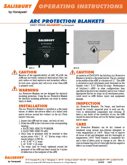
arc PrOTEcTION blaNkETs ONlY FrOM salIsbUrYby Honeywell 101 E. Crossroads Pkwy., Ste. A Bolingbrook, IL 60440 toll free ph (USA):877.406.4501 toll free fax (USA):866.824.4922 ph:630.343.3700Salisbury by Honeywell © 2009 Honeywell International Inc. All Rights Reserved. APB-INSTR110309 ARC45-15ARC45-40CAUTION Because of the unpredictability of ARC FLASH, theAPB may not totally contain arc flash and arc blast, butonly reduce or limit explosive and incendiary effects.In such cases, injuries may still occur, even when APBis properly used.WARNING Arc Protective Blankets are not designed for electricalinsulating protection. Using the Arc Protective Blanketfor electrical insulating protection can result in seriousinjury or death. INsTAllATION The Arc Protective Blanket is installed as a flat panelbarrier, to deflect the adverse effects of a failed cableand/or devices around the worker/s in the Arc Flashhazard work area.1. Inspect the APB and tie straps, see back of card.2. Orient the APB in the work area to the correspondinglabeling:a. FACE THIS SIDE TO WORKERb. FACE THIS SIDE TO ARC3. Each loop or grommet shall be attached to firmanchor points with 1” X 42” Kevlar straps with atensile rating ≥ 4,000 lbs.a. 48” X 60” = 12 strapsb. 48” X 96” = 16 straps4. Tie straps shall be evenly tightened around theperimeter of the APB and there should be 4 inchesof deflection at the midpoint of the APB.CAUTIONAs noted in ASTM F2676, the Salisbury Arc Protective Blanket is tested as a flat panel barrier. The arc centered in the middle of the APB, at a distance of 12”. The APB is anchored at each attachment point furnished on the blanket, with 1” X 42” Kevlar tie straps. Performance of Salisbury’s APB’s in other configurations than specified in the above test standard, and/or uses without appropriate Kevlar tie straps on all attachment points, could result in APB failure, injury and equipment damage.INsPECTIONArc Protective Blankets, Tie Straps, and hardware should be visually inspected prior to each use for: worn or deteriorated components and stitching. If there is any doubt of the suitability of use, the APB should be removed from service for further inspection and/or repair CARE Arc Protective Blankets can be dry cleaned or laundered using normal non-chlorine detergents in water temperatures at 140o F. Rinse well to remove all traces of dirt and detergents and dry thoroughly at temperatures 140o F. Verify blanket is completely dry and is free of debris prior to storage or use. Best to store in blanket bag (out of white light that has negativeeffects on Aramid based materials)。
udc2300 霍尼韦尔通用控制器说明书
UDC 2300 Universal Digital Controller:Exceptional functionality at an affordable priceProven LeaderLine quality, accuracy, and valueThe UDC 2300 is a low cost, easy-to-use 1/4 DIN controller which provides accurate control of process variables including temperature, pressure, flow, level,and rotation.The UDC 2300 Controller shares the industry-leading human/machine interface (HMI) and many other features with the popular UDC 2000Controller, and it offers even more functionality with options including RS485 ASCII or Modbus* RTU communica-tions and auxiliary current output. Standard features include input/output isolation,Accutune II™ tuning with fuzzy logic overshoot suppres-sion, and a universal AC power supply.For the thousands of satis-fied UDC 2000 users, the UDC 2300 Controller isdownward-compatible to exist-ing UDC 2000 applications and installations.Because its dimensions are identical to the UDC 2000, theUDC 2300 Controller can be easily inserted into existing panel installations.Features / Options•Universal input with optional 2nd input:The UDC 2300 offers one standard universal input which accepts thermocouple, RTD, mA, mV and volt input types. The optional second input accepts mV and mA inputs and is used as a remote setpoint.•Accutune II with fuzzy logic:This standard feature provides a plug-and-play tuning algorithm that will accurately identify and tune most any process, including deadtime and integrating processes.Accutune II speeds up and simplifies startup, and allows retuning at any setpoint. Fuzzy logic suppresses process variable overshot resulting from setpoint changes or externally induced process disturbances. It operates independently from Accutune II tuning and allows more aggressive tuning to co-exist with smooth process variable response.•Output forms: Four output forms are available. Current (4-20mA DC), 5 amp electro-mechanical, 1 amp solid state relay (internal), or open collector output for usewith external relays.•Serial communications: The RS485 communications option is configurable for ASCII or Modbus RTU.•Input / Output isolation: Analog inputs and outputs are isolated from each other and all other circuits.•Auxiliary output: This option can be scaled from 4-20mA for 0 to 100% for any range and can representinput 1 or 2, PV , active setpoint, local SP1, devia-tion, or the control output.•Universal switching power: Operates on any line voltage from 90 to 264 VAC 50/60 Hz. 24VAC/DC power is optional.•Limit control: A limit control model has a latch-ing relay which is activated whenever the process variable (PV) goes above (High Limit) or below (Low Limit) a preset set-point value. An alarm message is displayed when the output is activated.Reset is achieved via a key on the front of thecontroller or an optional external switch. A Factory Mutual (FM) approved model is available.•High noise immunity: The UDC 2300 is designed to provide reliable, error-free performance in industrial environments that often disturb highly noise-sensitive digital equipment.•Standard features now include: Dual display, auto /manual, UL recognition, dual setpoints, setpoint ramp,failsafe outputs, timer and CE approval.•Moisture protection: IP65 / NEMA3-rated front face permits use in applications where it may be subjected to moisture, dust, or hosedown conditions.•FM approval and CSA certification available as an option on controller and limit models.•Quality assurance: The quality of the UDC 2300 is assured by a two-year warranty program which features replacement units in the event of malfunction. Com-prehensive customer support includes toll-free technical assistance.•Easy-to-configure: A bright, dedicated configuration display provides straightforward English prompts that allow easy setup with minimum time and effort.A tactile keyboard promotes quick and accurate entry of all data.Condensed Specifications51-52-58-16 (5M) 1/99•Highly secure: Non-volatile memory assures data integrity during loss of power. Four configurable security levels plus a four-character code prevent accidental or unauthorized changes to the process.Industrial Automation and ControlHoneywell Inc.U.S.A.: Honeywell Industrial Automation and Control, 16404 North Black Canyon Hwy., Phoenix, AZ 85053Canada: The Honeywell Centre, 155 Gordon Baker Rd., North York, Ontario M2H 3N7Latin America: Honeywell Inc., 480 Sawgrass Corporate Parkway, Suite 200, Sunrise, Florida 33325Japan: Industrial Operations Tokyo, 4-28-1 Nishi-Rokugo Ohtu-ku, Tokyo 144, JapanAsia: Honeywell Asia Pacific Inc., 101 Thomson Road, #06-00 United Square, Singapore 307591, Republic of Singapore Pacific Division: Honeywell Pty Ltd., 5 Thomas Holt Drive, North Ryde NSW Australia 2113Northern Europe and Southern Africa: Honeywell Ltd., Honeywell House, Arlington Business Park, Bracknell, RG 12 1EB, U.K.Central Europe: Honeywell A.G., Kaiserleistraße 39, D-63067 Offenbach, GermanyWestern and Southern Europe: Honeywell S.A., Avenue du Bourget 1, B-1140 Brussels, Belgium Eastern Europe: Honeywell Praha, s.r.o., Budejovicka 1, 140 00 Prague 4, Czech RepublicMiddle East: Honeywell Middle East Ltd., Khalifa Street, Sheikh Faisal Building, Abu Dhabi, U.A.E.©Honeywell Inc. Printed in U.S.A. Recycled Paper•Additional Options include:–Two alarms or a second control output and one alarm –Remote setpoint via Input 2–Digital input (mutually exclusive with auxiliary output and communications)–Setpoint program (six ramps + six soaks)–Customer ID tag –Rear terminal coverThe reliability, accuracy and quality of Honeywell’s industry-proven LeaderLine ® family of controllers are sec-ond to none and offer the best total value of ownership.The UDC 2300 is backed by a two-year warranty and, as with all Honeywell industrial products, is supported by the largest service network in the industry.Honeywell provides a complete line of temperaturesensors including thermocouples, RTDs, and non-contact sensors that are compatible with the UDC 2300 andother industrial control products.*Modbus is a trademark of Modicon.。
- 1、下载文档前请自行甄别文档内容的完整性,平台不提供额外的编辑、内容补充、找答案等附加服务。
- 2、"仅部分预览"的文档,不可在线预览部分如存在完整性等问题,可反馈申请退款(可完整预览的文档不适用该条件!)。
- 3、如文档侵犯您的权益,请联系客服反馈,我们会尽快为您处理(人工客服工作时间:9:00-18:30)。
霍尼韦尔CARE控制资料 霍尼韦尔CARE 控制器LON 2011年06月13日CARE 概述一个暖通空调(HVAC)控制系统一般有控制器和设备组成。
控制器可以是 EXCEL 5000系列的控制器。
设备按类型分为空调系统、冷冻水系统和热水系统常用控制系统:设备是一个被控的机械系统。
如,一个设备可以是温湿度控制器、锅炉、冷冻机、或者是由锅炉、加热器、水泵、传感器和其他装置组成的变风量系统(VAV)。
基于机械物理原理,每种装置都有其输入或者是输出。
控制器和设备通过它们的输入或输出连接。
设备与控制器的连接方式按使用的总线类型分 C-B us 或 LON-Bus。
设备通过运行在控制器中的应用程序控制(控制策略、逻辑开关、时间程序等)。
例如:传感器温度值变化,执行器驱动调节阀到适当的位置来补偿温度偏差。
CARE 控制系统模型:一个暖通空调控制系统在 CAR E 中由一个“控制器-控制点-设备连接图”模型来实现。
控制器:CARE 应用程序提供控制器一种智能化处理的能力,在控制器中可以存储程序和数据点的控制信息。
控制器与数据点交换信息,控制器接受数据点(输入点)状态信息,经 CPU 处理,输出对数据点(输出点)的控制信息。
设备原理图:设备的连接由一个表示设备的安装和布局情况的图表来描绘。
数据点:在图表的底部,箭头表示装备控制点的输入输出。
箭头包括颜色代码、方向(向下是输入,向上是输出)和一些表示额外信息的特殊符号。
点类型颜色三角形方向数字量输入绿色向下模拟量输入红色向下数字量输出蓝色向上模拟量输出紫色向上Flex 点浅蓝向上设备图表可以选择不显示元件符号,只用三角形箭头来表示控制点。
CARE 中通过是否和设备的输入输出点连接来区分物理点(硬件点)和软件点(虚拟点)。
软件点用来做为软件程序计算处理的结果。
控制点按照一定的标准来分类,比如:按点类型分模拟量和数字量等,按地址分(Oa Temp 表示室外空气温度)。
在 EXCEL5000 系统中,每个点都对应唯一的用户地址。
通过在设备图表中加控制策略、逻辑开关和时间程序,我们来控制装置(参考CARE 主要应用节)。
控制过程中,控制器和设备通过运行在控制器中的程序运算处理来交换数据。
控制点数据交换根据相关的控制逻辑等来执行。
工程:控制器和依附的设备的相关信息被保存在工程中。
如下:一个包括 4 个设备和 3 个控制器的工程工程—Honeywe ll 水塔热水设备------------------------控制器 1冷水设备------------------------控制器 2空调系统 1----------------------控制器 3空调系统 2----------------------控制器 3另外,参考码、授权用户名、订购号等信息也是工程的一部分。
总线类型:控制器和设备使用公用的通讯协议连接到一个通讯总线上,能够互相通讯。
CARE 支持其设计者霍尼韦尔的 C-Bus(本地 LON-Bus)、开放式的 LON-Bus(LonWorks)和第三方的总线类型如 Meter-Bus。
网络结构:在 CARE 中,除总线类型外,设备在总线上的物理分布通过网络结构来表示。
主要应用程序: CARE 提供 4 个主要的应用程序来设计控制程序:•●设备图表•●控制策略•●逻辑开关•●时间程序设备图表:实际的装置在 CARE 中用一个图表来表示,可以显示装置在设备的位置和分布顺序。
控制策略:在设备图表创建后,需要编写控制策略,它能使控制器智能化的管理操纵系统。
控制策略定义一个基于触发条件、数学计算和时间日程表等的控制回路。
控制可以基于模拟量、开关量。
CARE 提供了标准的控制算法如比例-积分-微分(PID)、取最小值、取最大值、取平均值和排序等。
逻辑开关:除了控制策略,对于开关量的控制如开关状态要在图表中编写逻辑开关。
开关逻辑是基于逻辑或、逻辑与和逻辑与非的逻辑表。
比如,开关逻辑可以定义回风机在送风机启动一段时间后启动。
时间程序:设置时间程序来控制设备的开关,使之与其使用时间相符。
定义一个每日时间表(如周日、周末、节假日)并分配给周时间表。
输入/输出的连接:根据使用的硬件和总线类型,CAR E 为设备与控制器提供两种连接方式:输入、输出。
端子分配(C-Bus):如果控制器和设备已经连接在 C-Bus 上,控制器会有 IP 或者分布式 I/O 模块。
那么装置的输出/输入相应的控制点将会自动的分配到控制器终端。
我们可以在控制器终端看到并可以重新布局。
绑定(开放式LON-Bus):如果一个 LON 控制器和其他的第三方 LON 装置连接到一个开放式的 LON-Bus 上,控制器既不使用 IP 也不用 I/O 模块。
相反地,装置输入/输出对应的控制点是没有赋值的,那么需要通过拖、拽没赋值的点到 L ON 装置的点位(称为网络变量NVs)。
这个连接各个 LON 装置的过程称做绑定。
下载应用程序到控制器:在设备完成原理图、控制策略、逻辑开关和时间程序的编辑后,应用程序文件可以编译成控制器可识别的格式。
然后这个文件可以下载到控制器并开始调试控制器。
CARE 特性CARE 软件提供一种图形化编程工具,来方便的编写能下载到 EXCAL5000 控制器的程序。
CARE 包括以下几个主要的内容:•C-Bus 和 LON-Bus 网络●原理图●控制策略●逻辑开关●点属性●点映射文件(可选)●时间程序●文档管理支持的控制器和装置:●Excel 10/50/80/100/500/600●Excel S mart 控制器●Smart I/O 模块●分布式 I/O 模块●OPS 控制器●Excel IRC●Excel E link 可兼容 LON 协议和其他霍尼韦尔的LON 装置的线性阀门执行器 M7410G●第三方的 LON 装置Excel 10 应用软件:Excel 10 应用软件使用一个 Excel 10 区域管理控制器作为 C-Bus 连接的 EXCEL5000 与 E-Bus 连接的 Excel 1 0 控制器。
为了实现 C-Bus 和 E-Bus 之间的点映射,Excel 1 0 区域管理控制器应具有除没有硬件点外的 Excel 100 的所有功能。
Excel 10 应用软件包括使用 VAV1(标准变风量系统)的 Q7 750A1xxx(1000 系列)和包括 Q7750A2xxx 区域管理器的 2000 系列,它使用 VAV2 和 FC U 式的通讯控制器。
CARE4 .01.00 只能应用于 2000 系列。
因为在 CARE 中只能完成一部分,最终要在E-Vision 软件工具完成。
整个过程在 Excel E-Vision 使用向导 74-258 8 中有说明。
这个向导中 Excel 10 应用软件章节中介绍了 CARE 的设计步骤。
OPS 控制器:OPS 控制器(开放式点位服务器),先前称为 OLink 控制器。
在CARE 中能象 Exce l 500 控制器一样定义。
外部总线系统信息比如来自 M-Bus,能够通过子系统点位与 CARE 点位的简单映射集成到一起。
CARE运行界面(不能上传图片,还请高手指教)启动 CARE 后,你可以看到 3 个分区的 CARE 界面。
设备分支树:设备树提供一个关于工程逻辑结构的总的轮廓。
这有助于你管理、组织你的工程中用到的组件(控制器、设备表、点位)。
网络结构分支树:网络树提供一个关于工程的总线系统和网络结构的总的轮廓,这有助于你管理、组织你的工程中用到的网络组件(C-Bus 控制器、L ON 装置、LON 对象等)。
展开与收缩目录树的显示:点击+、-能够展开和收缩显示的目录树的大小。
信息与编辑面板:在设备树和网络树中选择不同的项目会在右边的面板中出现不同的界面。
它显示你选择的项目的属性信息。
例如:它能显示一个工程的名字、客户、计量单位等信息,它也能显示一个选定的控制器的端子分配情况设备分支树一个工程的逻辑结构可以在一个分级的逻辑设备树中表示出来。
它能够显示出控制器与其下的设备表以及按模拟量输入、模拟量输出、开关量输入、开关量输出四种类型分组的点位列表。
设备逻辑树:设备逻辑树的图表含义如下:工程(最多一个)控制器设备表点类型单个点下面的信息能够在右边的面板中点击设备树中相应的部分:工程、控制器、设备和点位的属性端子分配表设备原理图查看和编辑属性:在设备树中点击想查看的部分(工程、控制器、设备、点位)可以在右边的编辑面板中看到相应的属性。
例 3:工程属性如想看到详细的工程、控制器、设备、点位属性的编辑请参照相应章节。
查看设备原理图:在设备树中点击设备,然后在右面的面板中选择原理图(Schema tic)可以显示设备原理图(只能查看)。
要创建和编辑一个设备原理图,请参照创建设备原理图章节。
网络分支树.总线类型和网络结构:一个工程可以使用多个不同的总线类型(C-Bus ,LON-Bus 等)来构建网络。
例 4 :具有多种总线类型(C-Bus 和 LON-Bus )的工程显示在设备树的下面的分级网络树构成一个网络。
网络树中显示两种基本的总线类型,C-Bus 和 L ON-Works。
每个总线都默认的分级,允许按照建筑物中的网络组件的实际分布来安排结构。
C-Bus 目录下包括一个默认的 C-Bus 1 子目录。
再创建子目录的话会自动按数字递增生成。
C-Bus 子目录显示实际的工程C-Bus 网络结构,以及包含的控制器。
注意:子目录名字可以选备选名也可自由编辑。
例如,默认的 C-Bus1 子目录可以命名为 Area 1 或 Block A。
LON-Works 目录显示 LON-B us 的网络界面。
默认的被分成实际部分-Channels(通道)和逻辑部分-Default System 默认系统。
通道目录包括一个默认的 Channe l_1 子目录。
可以创建其他的通道并可自由编辑。
在通道目录下,通道的布局显示出使用的物理媒介如双绞线并列出其下连接到通讯线上的所有 LON 设备。
Default Sy stem(默认系统)体现 LON-Bus 结构,能提供 LON 装置、LON 对象、网络变量等必要功能。
通常包含以下组件:子系统(在默认系统下创建)●LON 装置●LON 对象●NVS(网络变量)●SCPTS(标准属性配置)提示:默认系统和子系统还可以有下级子系统,命名做“默认系统”和“子系统”是做一个范例,用户能自由编辑。
查看和编辑属性,在网络树中点击想查看的部分(工程、子系统、LON 装置、LON 对象、网络变量),可以在右边面板中查看和编辑相应的属性。
四、3 设备树与网络树间关联在工程设计过程中,为工作方便,同时操作设备树和网络树是可以的。