ACS500数据采集器-装置使用说明书
数据采集器现场安装及调试操作指南
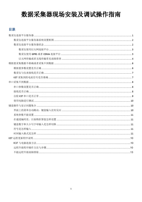
数据采集器现场安装及调试操作指南目录数采仪连接平台服务器 (1)数采仪连接平台服务器系统设置框图 (2)数采仪连接平台服务器状态 (2)数采仪使用以太网连接平台 (3)数采仪使用GPRS或者CDMA连接平台 (3)以太网传输或者无线传输常见故障排查 (4)模拟量采集数据不准确或者采集不到数据 (6)模拟量参数设置是否正确 (6)数采仪与仪表接线是否正确 (7)K37采集到的电流信号是否准确 (7)串口采集不到数据 (8)串口参数设置是否正确 (8)接线是否正确 (8)自检K37串口是否正常 (9)使用电脑进行测试 (10)键盘操作与显示问题集合 (10)界面上的菜单自动跳动,键盘输入没有反应 (10)系统参数不能设置 (11)在通道编码里,污染物折算值怎样设置 (11)键盘数字和大小写字母输入是怎样切换 (11)符号是怎样输入 (11)时间输入格式是怎样 (11)K37远程更新程序说明 (10)K37与电脑连接方法 (10)远程升级程序操作方法与步骤 (10)不能远程升级故障排除 (13)一、数采仪连接平台服务器※ 数采仪连接平台服务器系统设置框图采集器参数设置系统编码MN 号码保存周期31-烟气32-污水环保局统一分配根据环保局要求分钟历史数据上传周期设置网络参数设置以太网GPRSCDMAIP 地址子网掩码网关APN拨号名称拨号密码移动公网:cmnet 联通公网:uninet 专网有专门APN公网拨号名称:card 公网拨号密码:card通信链路0-关闭1-以太网2-GPRS 3-CDMA中心地址中心端口实时周期心跳周期平台IP 地址平台监听端口环保局要求实时数据周期一般默认为2分钟服务器参数设置连接平台设置第一步第二步第三步数采仪连接平台服务器状态在数采仪显示屏左上角,将数采仪与平台连接状态显示出来。
如果屏幕的左上角出现天线符号,则表示当前有链路在使用无线通信方式GPRS 或者CDMA 。
如果没有天线符号,则会出现字符“E ”,代表当前只使用了以太网通信方式。
ACS550变频器说明书(中文版)
Drive IT 低压交流传动用户手册ACS550-01 变频器 (0.75...90 kW)2ACS550 用户手册ACS550 变频器手册通用手册ACS550-01/U1 用户手册 (0.75…90 kW) / (1…150HP)•安全指南•安装•起动•诊断•维护•技术数据ACS550-02/U2 用户手册 (110…355 kW) / (150…550 HP)•安全指南•安装•起动•诊断•维护•技术数据ACS550 技术参考手册•详细产品描述–产品技术描述,包括外形尺寸图–柜体安装信息,包括功率损耗–软件和控制包括完整参数描述–用户接口和控制连接–完整可选件描述–备件–其它等•实际工程指导–PID & PFC 工程指导–安装和选型指导–诊断和维护信息–其它等可选件手册( 现场总线适配器, I/O 扩展模块等,手册和可选件一起发货 )继电器输出扩展模块•安装•起动•诊断•技术数据ACS550 用户手册3安全指南警告! 只有专业技术人员才允许安装 ACS550!警告! 即使电机已经停止, 功率端子 U1, V1, W1和 U2, V2, W2 以及UDC+, UDC-或 BRK+ , BRK- 上面依然存在危险电压!警告!主回路电源得电后即存在危险电压。
电源断开后等候5分钟(让中间回路电容充分放电)再打开前面板。
警告!ACS550断电后,在继电器端子上 ( R01…R03 )依然可能有外部危险电压。
警告! 当两个或两个以上的变频器的控制端子并联使用时,用于控制连接的辅助电源应来自同一个单元或外部电源。
警告! ACS550-01/U1不是可以在现场维修的机器。
不要试图修理损坏的单元,请与供应商或当地授权的维修站联系。
警告! 当输入电源短时断电之后再次恢复时,如果外部运行指令为ON,ACS550 将自动起动。
警告! 散热器的温度可能很高。
参见127页的“技术数据”。
警告!如果变频器用在浮地电网时,请拆下螺钉EM1和EM3(外形尺寸R1…R4)或F1和F2(外形尺寸 R5 或R6)。
二代数据采集器使用说明书
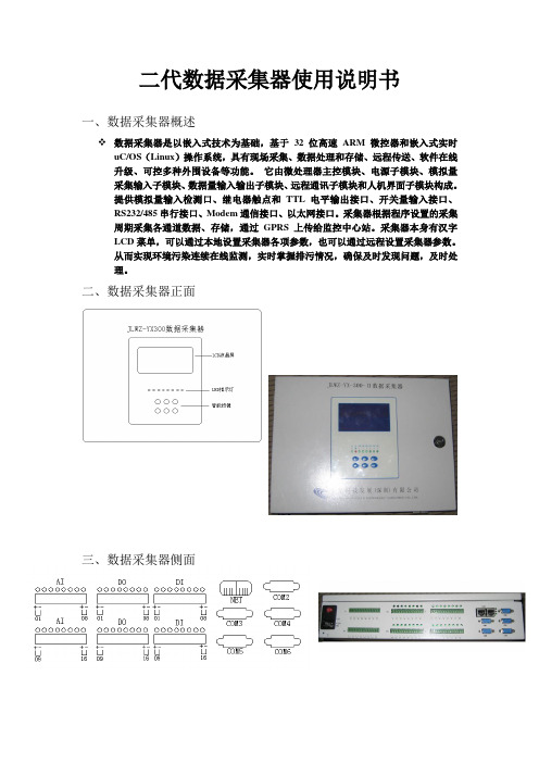
二代数据采集器使用说明书一、数据采集器概述数据采集器是以嵌入式技术为基础,基于32位高速ARM微控器和嵌入式实时uC/OS(Linux)操作系统,具有现场采集、数据处理和存储、远程传送、软件在线升级、可控多种外围设备等功能。
它由微处理器主控模块、电源子模块、模拟量采集输入子模块、数据量输入输出子模块、远程通讯子模块和人机界面子模块构成。
提供模拟量输入检测口、继电器触点和TTL电平输出接口、开关量输入接口、RS232/485串行接口、Modem通信接口、以太网接口。
采集器根据程序设置的采集周期采集各通道数据、存储,通过GPRS上传给监控中心站。
采集器本身有汉字LCD菜单,可以通过本地设置采集器各项参数,也可以通过远程设置采集器参数。
从而实现环境污染连续在线监测,实时掌握排污情况,确保及时发现问题,及时处理。
二、数据采集器正面三、数据采集器侧面四、数据采集器内部图主串口1)主控板2)模拟输入板模拟通道JP01~JP16(两脚短路是电流型,断开是电压型)3)串口板数据采集器主要组成部件说明1、模拟板:用于将外围设备输出(4-20mA)的模拟信号转成数字信号。
2、数字输入/输出板:用于数字量输入,及反控设备。
3、串口扩展板:用于连接网络,采集外围设备输出量。
4、主控板:处理外围设备输入数据,并上传给监控中心。
5、按键板:数据采集器设置输入,状态指示。
6、LCD显示屏:用来显示信息7、开关电源:给数据采集器提供稳定电源。
8、蓄电池:在停电状态下给数据采集器供电,起备用电源作用。
五、数据采集器主界面开机工作后,机器工作正常,LCD第一行显示输入密码,第2行显示宇星科技,第3行显示系统的日期和时间,第4行显示监测的实时因子数据。
按任意键LCD屏幕亮后,要求输入密码,输入正确的密码后进入菜单设置。
六、数据采集器密码操作6个智能按键分别为:上“▲”,下“▼”,左“◄”,右“►”,“取消”,和“确认”。
初始普通用户密码为:“▲”,超级密码为“▲▼►▼▲”。
数据采集器采集各种设备和仪表的配置说明(doc 79页)
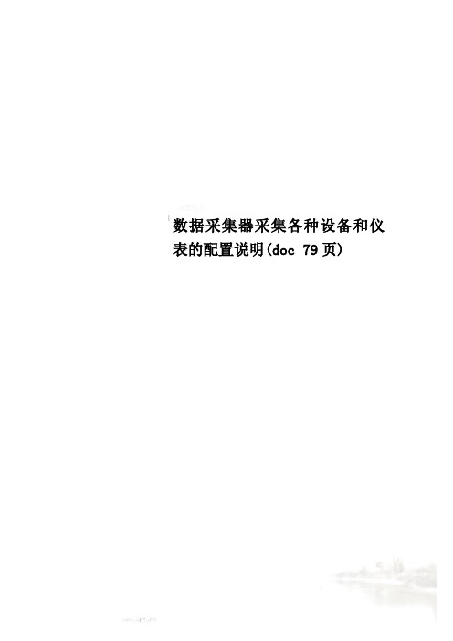
数据采集器采集各种设备和仪表的配置说明(doc 79页)DED-BA-E7101数据采集器设备和仪表配置说明(内部使用,未完待续)重庆德易安科技发展有限公司Chongqing EHS Technology Development Co.,Ltd.目录界面概述 (20)1.沈阳航发热能表 (23)1.1.航发超声波表配置231.2.航发机械表配置242.德易安温控器 (29)3.江阴众和电表(645-2007) (30)4.埃美柯水表 (32)5.TTD温度传感器 (33)6.深圳北电电表(645-1997) (35)7.长沙索拓温控器 (36)8.宁波甬港热能表 (37)17.浙江立新DDS238-4单相电子式电能表 .. 5917.1.采集端口配置:5917.2.配置温控器地址:6017.3.采集数据配置:6017.4.采集数据显示:6017.5.解析:6018.浙江立新DDS238-7三相电子式电能表 .. 6018.1.采集端口配置:6018.2.配置温控器地址:6118.3.采集数据配置:6118.4.采集数据显示:6118.5.解析:6219.深圳北电电表三相四线电子式有功电能表(645-1997) (62)19.1.采集端口配置:6219.2.配置表地址:6219.3.采集数据配置:6219.4.采集数据显示:6320.浙江立新DTS238-7 ZN/S型三相四线电子式电能表ModBus (63)20.1.采集端口配置:6320.2.配置表地址:6320.3.采集数据配置:6420.4.采集数据显示:6720.5.解析:6721.21.德易安温湿度传感器 (67)21.1.采集端口配置:6821.2.配置表地址:6821.3.采集数据配置:6821.4.解析:6822.浙江立新DTS238-7 ZN/S型三相四线电子式电能表T645-2007 (68)22.1.采集端口配置:6822.2.配置表地址:6922.3.采集数据配置:6922.4.采集数据显示:7322.5.解析:7323.华控信业室外温湿度传感器 (73)7323.2.配置表地址:7423.3.采集数据配置:7423.4.采集数据显示:7523.5.解析:7524.光照度传感器 (75)24.1.采集端口配置:7524.2.配置表地址:7524.3.采集数据配置:7624.4.采集数据显示:7624.5.解析:7725.中力格林配置方法 (77)7725.2.配置表地址:7725.3.采集数据配置:7825.4.采集数据显示:7825.5.解析:7826.浙江立新DTS238型三相四线有功电能表(645-1997) (79)26.1.采集端口配置:7926.2.配置表地址:7926.3.采集数据配置:7926.4.采集数据显示:8027.深圳北电单相电子式电能表(645-2007)808027.2.配置表地址:8027.3.采集数据配置:8027.4.采集数据显示:8127.5.解析:8128.F2000TSM-VOC系列变送器 (81)28.1.采集端口配置:8128.2.配置表地址:8128.3.采集数据配置:8228.4.采集数据显示:8228.5.解析:8229.EDA9033F三相电参数 (82)8229.2.配置表地址:8329.3.采集数据配置:8329.4.采集数据显示:8329.5.解析:8330.RS485压力变送器 (84)30.1.采集端口配置:8430.2.配置表地址:8430.3.采集数据配置:8430.4.采集数据显示:8430.5.解析:8431.EX8-214 三相电子式电能表(力创97—645协议) (85)31.1.采集端口配置:8531.2.配置表地址:8531.3.采集数据配置:8531.4.采集数据显示:8531.5.解析:8532.EX8-214 三相电子式电能表(力创07—645协议) (86)32.1.采集端口配置:8632.2.配置表地址:8632.3.采集数据配置:8632.4.采集数据显示:8632.5.解析:33.EX8 +三相电子式电能表(力创ModBus 通信协议) (87)33.1.采集端口配置:8733.2.配置表地址:8733.3.采集数据配置:8733.4.采集数据显示:8733.5.解析:8734.山东DDSD—113型电能表(力创97—645协议) (88)34.1.采集端口配置:8834.2.配置表地址:8834.3.采集数据配置:8834.4.采集数据显示:34.5.解析:8835.建恒热能表 (88)35.1.采集器端口配置(功能码:3 命令码:8080)(采集器程序2.84a) (89)35.2.配置表地址8936.上海安特瑞三相四线表 (89)36.1.采集器端口配置8936.2.一次侧有功电能8936.3.相电压9036.4.频率9037.江阴华诺HN530E三相四线有功电能表. 9137.1.(测试时烧写的程序是das_multi_FMGS_v2.82a01_20150924.hex) 9138.照明模块 (92)38.1.采集器端口的配置9338.2.配置表地址9338.3.采集数据配置9338.4.采集数据显示9339.机电模块 (94)39.1.采集端口配置9439.2.配置表地址9439.3.采集数据配置9439.4.采集数据显示9440.华邦三相四线电子式有功电能表(97-645)9540.1.采集器端口配置9540.2.配置表地址9540.3.采集器数据显示9541.大连道盛热量表 (96)41.1.端口配置9641.2.通道配置9642.威胜电表DTSY341电子式预付费614-2007 (96)42.1.端口配置9642.2.配置表地址9642.3.数据格式9743.上海广合DDS850Y-BK 电子式预付费 (97)43.1.端口配置9743.2.地址配置9743.3.数据格式9843.4.串口修改地址9844.常州驰高电表CG194E-9S4/9S7/9S9/9S9A9844.1.端口配置9844.2.地址配置9844.3.数据格式9945. (99)45.1.端口配置9945.2.地址配置9946.数据格式 (100)界面概述A: 根据采集器下连接的设备选择相应的协议和参数,选择好后单击“下载采集器端口配置”都配好需要保存配置时,单击上方的“保存配置”。
ABB变频器操作说明书-(最新版-修订)

CONST SPEED
ABB
ACS550
RELAY OUTPUT ( 继电器输出)
1404-1418
继电器1-6的延时(3600S)
© Company name - 20
1406 1408
1407 1408
ABB
ACS550
Parameter lock ( 参数锁定)
参数1602和1603
torque limits Critical
frequencies lock-out
Extensive protection features
Preprogrammed software functions
保护特性
Hardware features
▪ Overcurrent ▪ DC overvoltage ▪ DC undervoltage ▪ Power plate
ABB
© Company name - 8
ACS550
应用宏: PID 控制
该应用宏用于多种闭环控制系统,如压力控制,流量控制等。
输入信号 • 模拟给定(AI1) • 实际值(AI2) • 起/ 停– 手动/PID (DI1, 6) • EXT1/EXT2 选择(DI2) • 恒速选择(DI3, 4) • 运行允许(DI5)
Push-button use 按钮控制
Alternating the direction 交替变换转动方向
Ref. in- and decrease through Dis 数字信号来控制给定
Two control modes (HVAC) 两种外部控制模式
Closed loop control: pressure, flow ... 闭环控制系统:压力,流量 For pump and fan
ACS550变频器说明书(中文版)

Drive IT 低压交流传动用户手册ACS550-01 变频器 (0.75...90 kW)2ACS550 用户手册ACS550 变频器手册通用手册ACS550-01/U1 用户手册 (0.75…90 kW) / (1…150HP)•安全指南•安装•起动•诊断•维护•技术数据ACS550-02/U2 用户手册 (110…355 kW) / (150…550 HP)•安全指南•安装•起动•诊断•维护•技术数据ACS550 技术参考手册•详细产品描述–产品技术描述,包括外形尺寸图–柜体安装信息,包括功率损耗–软件和控制包括完整参数描述–用户接口和控制连接–完整可选件描述–备件–其它等•实际工程指导–PID & PFC 工程指导–安装和选型指导–诊断和维护信息–其它等可选件手册( 现场总线适配器, I/O 扩展模块等,手册和可选件一起发货 )继电器输出扩展模块•安装•起动•诊断•技术数据ACS550 用户手册3安全指南警告! 只有专业技术人员才允许安装 ACS550!警告! 即使电机已经停止, 功率端子 U1, V1, W1和 U2, V2, W2 以及UDC+, UDC-或 BRK+ , BRK- 上面依然存在危险电压!警告!主回路电源得电后即存在危险电压。
电源断开后等候5分钟(让中间回路电容充分放电)再打开前面板。
警告!ACS550断电后,在继电器端子上 ( R01…R03 )依然可能有外部危险电压。
警告! 当两个或两个以上的变频器的控制端子并联使用时,用于控制连接的辅助电源应来自同一个单元或外部电源。
警告! ACS550-01/U1不是可以在现场维修的机器。
不要试图修理损坏的单元,请与供应商或当地授权的维修站联系。
警告! 当输入电源短时断电之后再次恢复时,如果外部运行指令为ON,ACS550 将自动起动。
警告! 散热器的温度可能很高。
参见127页的“技术数据”。
警告!如果变频器用在浮地电网时,请拆下螺钉EM1和EM3(外形尺寸R1…R4)或F1和F2(外形尺寸 R5 或R6)。
数据采集使用说明书
G01通用数据采集仪和分析系统使用说明书中国地震局工程力学研究所目录一.功能和用途说明--------------------------------------------------------------3二.软件安装步骤说明----------------------------------------------------------3三.软件使用说明-----------------------------------------------------------------4四.采集仪使用说明------------------------------------------------------------24一、功能和用途说明本系统包括采集仪和软件两个部分。
采集仪为16位、USB总线、最高采样率可达到400KHz的16通道的数据采集仪器。
软件有数据采集、数据触发采集、时域滤波、波形编辑、数据微分、积分和统计、频域分析、自动判断结构固有频率、结构振型分析、多通道信号失真度测量、虚拟电压表和示波器共11个模块组成。
提供了多种采集方式、丰富的数据时域分析、频率分析等功能。
可用于地脉动、结构脉动、爆破、桥梁、大坝和结构等建筑物的健康诊断和分析、环境振动影响分析、结构振型分析等。
二、安装步骤1.先安装驱动程序。
解压缩“数据采集驱动程序”文件,解压缩后选择“USB2080”文件里面的“app”文件,打开“app”文件,点击setup。
如果已经安装了波速测量软件、挠度测量软件、振动台标定软件中的任何一个驱动程序,在这不需要再安装驱动程序,直接安装应用程序。
2.安装应用软件。
打开”数据采集应用软件”文件,点击setup。
安装完后。
3.安装完后,连接好仪器和电脑,电脑会自动安装仪器的USB口驱动,按照提示分别选择“自动安装”、“只安装一次”,此过程需要一定的时间,请耐心等待。
4.到电脑的“所有程序”里就可以看到了“中国地震局工程力学研究所数据采集软件”了。
ACS550用户使用手册.

ACS550 用户使用手册纸189页嵌入式现场总线概览设立的ACS550能够使用标准的串行通信协议从外部系统接受控制。
当使用串行通讯时,ACS550能够做到下面的事情:从现场总线接受所有的控制信息或者被总线控制的集合体和其他可用的控制路径所控制,例如数字或模拟的投入和控制面板。
两个基本串行通信可被配置嵌入式现场总线-----采用RS485接口使用在终端X1:28….32上的控制板,一种控制系统通信网的驱动器使用的Modbus 协议。
(对于协议和外形的描述,参见这一章后面的Modbus 协议电子数据和ABB 控制配置文件技术数据两部分)现场总线适配器-----参见221页现场总线适配器章节。
控制接口总体上, Modbus 和驱动器之间的基本控制接口包括下面的部分:输出字---控制字---参考资料1---参考资料2输入字---状态字---实际价值1---实际价值2纸190页---实际价值3---实际价值4---实际价值5---实际价值6---实际价值7---实际价值8这些字的内容被概况定义了,关于使用的概况的细节参见209页ABB 控制配置文件技术数据部分。
说明:关于字输入和输出的使用是从现场总线控制器的角度看的,例如输出描述数据流从现场总线控制器到驱动器,从驱动器的角度显示的是输入。
规划网络规划应解决下列问题:什么类型和数量的设备必须是连接到网络?什么控制信息必须设置到驱动器?什么反馈信息必须送交从驱动器的控制系统?机械和电气安装----嵌入式现场总线警告!连接应该只在驱动器断开电源时。
驱动器终端28….32是为了RS485通信。
使用贝尔登9842或相等物。
贝尔登9842是一种扭曲的,对屏蔽电缆的波阻抗是120欧姆。
在使用上述其中一种双屏蔽双绞线的485链接。
使用此对连接所有A (- )终端一起和所有B(+ )终端在一起。
使用一个电线在其他两个的逻辑地面(终端31 ),造成一个电线使用。
在任何时候不直接连接地面485网络。
ABB ACS550-01, IP21 UL Type 1, Quick Start 说明书
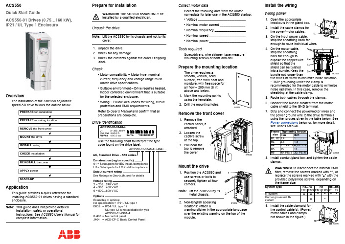
ACS550Quick Start GuideACS550-01 Drives (0.75…160 kW),IP21 / UL Type 1 EnclosureOverviewThe installation of the ACS550 adjustablespeed AC drive follows the outline below.ApplicationThis guide provides a quick reference forinstalling ACS550-01 drives having a standard enclosure.Note:This guide does not provide detailedinstallation, safety or operationalinstructions. See ACS550 User’s Manual forcomplete information.Prepare for installationWARNING! The ACS550 should ONLY beinstalled by a qualified electrician.Unpack the driveNote:Lift the ACS550 by its chassis and not by its cover.1.Unpack the drive.2.Check for any damage.3.Check the contents against the order / shippinglabel.Check•Motor compatibility – Motor type, nominalcurrent, frequency and voltage range mustmatch drive specifications.•Suitable environment – Drive requires heated,indoor controlled environment that is suitablefor the selected enclosure.•Wiring – Follow local codes for wiring, circuitprotection and EMC requirements.Refer to User’s Manual and confirm that allpreparations are complete.Drive identificationUse the following chart to interpret the type code found on the drive label.Collect motor dataCollect the following data from the motornameplate for later use in the ACS550 startup:•Voltage __________________________•Nominal motor current ______________•Nominal frequency _________________•Nominal speed ____________________•Nominal power ____________________Tools requiredScrewdrivers, wire stripper, tape measure,mounting screws or bolts and drill.Prepare the mounting locationThe drive requires asmooth, vertical, solidsurface, free from heat andmoisture, with free space forair flow – 200mm (8in)above and below.1.Mark the mounting pointsusing the template.2.Drill the mounting holes.Remove the front cover1.2.3.Mount the drivewarning sticker in the appropriate languageover the existing warning on the top of themodule.Install the wiringWiring power1.Open the appropriateknockouts in the gland box.2.Install the cable clamps forthe power/motor cables.3.On the input power cable,strip the sheathing back farenough to route individual wires.4.On the motor cable,strip the sheathingback far enough toexpose the copper wireshield so that theshield can be twistedinto a bundle. Keep thebundle not longer thanfive times its width to minimize noise radiation.– 360° grounding under the clamp isrecommended for the motor cable to minimizenoise radiation. In this case, remove thesheathing at the cable clamp.5.Route both cables through the clamps.6.Connect the bundle created from the motorcable shield to the GND terminal.7.Strip and connect the power/motor wires andthe power ground wire to the drive terminalsusing the torques given in the table below. SeePower connections below or, for more detail,see User’s Manual.8.Install conduit/gland box and tighten the cableclamps.WARNING! To disconnect the internal EMCfilter, remove the screws marked with “-”, orreplace the screws marked with “” with theprovided polyamide screws, depending onthe frame size.9.Install the cable clamp(s) forthe control cable(s). (Power/motor cables and clampsnot shown in the figure.)PREPARE for installation PREPARE mounting location REMOVE the front coverMOUNT the drive INSTALL wiring CHECK installation REINSTALL the cover APPLY power START-UPSernoACS550-01-08A8-4*2030700001*U1 3~ 380...480 VI2N/ I2hd 8.8/6.9 APN/Phd 4.0/3.0 kWACS550-01-08A8-4+J404+…AC, Standard Drive – 550 seriesSee Ratings in User’s Manual for detailsConstruction (region specific)Output current ratingVoltage rating2=208…240V AC4=380…480V AC6=500…600V ACExamples of options:No specification=IP21 / UL type 1B055=IP54 / UL type 12UL type 12 is not available for typeACS550-01-290A-4.0J400=No control panelJ404=ACS-CP-C Basic Control Panel01=Setup/parts for IEC install./complianceU1=Setup/parts for US install./complianceOptionsFramesizeTightening torqueN·m lb·ftR1, R21.41R3 2.5 1.8R4 5.6; PE: 24; PE 1.5R51511R640; PE: 830; PE: 6System type R1...R3R4R5...R6EM1EM3EM1EM3F1F2IT system----Corner grounded TNsystem-Wiring the controls1.Strip control cable sheathingand twist the copper shield into a bundle. 2.Route control cable(s)through clamp(s) and tighten clamp(s). 3.Connect the ground shieldbundle for digital and analog I/O cables at X1-1. (Ground only at the drive end.)4.Strip and connect the individual control wires to the driveterminals. Use a tightening torque of 0.4 N·m (0.3 lb·ft). See Control connections below or, for more information, see User’s Manual . 5.Install the conduit/gland box cover (1screw).Control connectionsNote 1.Jumper setting (two switch types possible):Note 2. Code: 0=open, 1=connectedWARNING! The maximum voltage for digital inputs is 30 V.Check installationBefore applying power, perform the following checks.Reinstall the cover1.Align the coverand slide it on. 2.Tighten the captive screw. 3.Install the controlpanel.Apply powerAlways reinstall the front cover before turning power on.WARNING! The ACS550 will start upautomatically at power up, if the external run command is on.1.Apply input power.When power is applied to the ACS550, the green LED comes on.Note: Before increasing motor speed, check thatthe motor is running in the desired direction.Start-upIn start-up, enter motor data (collected earlier) and, if needed, edit parameters that define how the drive operates and communicates.Assistant Control PanelThe Start-up Assistant steps through typical start-up selections, and runs automatically upon the initial power up. At other times, use the steps below to run the Start-up Assistant.For common parameters and menu items,use the Help key to display descriptions.If you encounter alarms or faults, use the Help key or refer to chapter Diagnostics in User’s Manual .Basic Control PanelThe Basic Control Panel does not include the Start-up Assistant. Refer to section How to start up the drive in User’s Manual and manually enter any parameter changes desired.(U2, V2, W2)(U1, V1, W1)(U2, V2, W2)(U1, V1, W1)Frame size R6Optional brakingFrame size TerminallabelsBrake options R1, R2BRK+, BRK-Brake resistor R3…R6UDC+, UDC-•Braking unit•Chopper and resistorbraking below.below.DI3DI4Output 00Reference through AI110CONSTANT SPEED 1 (1202)01CONSTANT SPEED 2 (1203)11CONSTANT SPEED 3 (1204)1SCR 2AI13AGND 410V 5AI26AGND 7AO18AO29AGND 1024V 11GND 12DCOM 13DI114DI215DI316DI417DI518DI619RO1C 20RO1A 21RO1B 22RO2C 23RO2A 24RO2B 25RO3C 26RO3A 27RO3BExt. freq. ref. 1: 0…10V Output freq.: 0…20mA Start/Stop: Active = start Fwd/Rev: Active = rev. dir.Constant speed sel.2Constant speed sel.2Ramp pair: Active = 2nd ramp pair.Relay output 1Default operation:Relay output 2Default operation:Relay output 3Default operation:X1Output current: 0…20mA Not usedAnalog input com. Not usedAnalog output com.Aux. volt. commonDigital input com. for all Analog input com.Ready = 19/21 connected Running = 22/24 connected Fault(-1) =25/27 connected (Fault => 25/26 connected)Ref. voltage 10V DC Aux. volt. output +24V DC ABB Standard macroSignal cable shield (screen)J1AI1: 0 (10V)AI2: 0(4)…20mAONONON12or J1CheckEnvironment conforms to specifications.The drive is mounted securely.Proper cooling space around the drive.The motor and driven equipment are ready for start.For IT systems and corner grounded TN systems: The internal EMC filter is disconnected (see the table in Wiring power ).The drive is properly grounded.Input power (mains) voltage matches the drive nominal input voltage.The input power (mains) terminals, U1, V1, W1, are connected and tightened as specified.The input power (mains) fuses are installed.The motor terminals, U2, V2, W2, are connected and tightened as specified.Motor cable is routed away from other cables.NO power factor compensation capacitors are in the motor cable.Control terminals are wired and tightened as specified.NO tools or foreign objects (such as drill shavings) are inside the drive.NO alternate power source for the motor isconnected – no input voltage is applied to the output of the drive.?C o d e : 3A F E 68243513 R E V E / E NE f f e c t i v e : 2009-07-07S u p e r s e d e s : 2007-04-16。
数据采集器使用说明书

1.概述1.1 引言该数据采集器采用当代微电子技术,对电力设备运行中的数据进行记录、存储、显示。
具有工作可靠、操作简单、数据便于收集和计算机分析等特点。
U盘作为新型移动存储设备,以体积小、速度高、抗震动、通用性强的特点倍受青睐。
该数据采集器可将采集的数据直接存储到普通U盘中。
数据采集完毕后,用户可直接从采集器上取下U盘,利用计算机方便地实现对采集数据的收集和分析处理。
1.2 系统组成该数据采集器主要有五部分组成:电源单元、交流采样单元、处理单元、U盘存储单元、显示单元,框图如下图1所示。
图1 数据采集器框图1.3 功能介绍1.3.1 电力数据采集数据采集器能采集、存储、显示电力设备运行中的实时三相电压、三相电流、有功功率、无功功率、功率因素、U盘读取之后的电能累计值。
电能数据保存时带有时标。
1.3.2 数码显示该数据采集器面板采用数码管分别进行功能和数值显示。
功能显示为2位数码管显示。
功能显示码“UA”、“UB”、“UC”、“IA”、“IB”、“IC”、“pt”、“qt”、“EA”、“PF”分别代表“A相电压”、“B相电压”、“C相电压”、“A相电流”、“B相电流”、“C相电流”、“有功功率”、“无功功率”、“电能”、“功率因素”。
用户可以使用功能按键、增加按键、减少按键使功能显示码循环显示。
数值显示为4位数码管显示。
当电能数值超过4位数时,功能显示码仅用左边的数码管显示为“E”,功能显示码右边的数码管和4位数值显示数码管一起构成5位数码管来显示当前的电能数值。
1.3.3 数据管理和存储数据采集器每隔15分钟将电力运行数据存储在处理单元的控制芯片内部flash里面。
用户定期(建议半个月一次,最长一个月)可以使用U盘对存储数据进行读取,以txt文件形式存储,以当前的月日时分信息进行命名。
读取时,U盘读取指示灯LUSB点亮,读取操作完成后,U盘读取指示灯LUSB熄灭,控制芯片内部flash中数据将被清空。
艾克夫sl500中文说明书

图形显示采用10.5"液晶显示器、16种颜色、分辨率640 x 480 pixels像素形象显示。
基本菜单控制程序启动时,计算机显示一个主屏。
第一屏称为主菜单,它形象地显示采煤机及其主要参数。
用户操作功能键F1 – F8可以直接转换基本菜单。
.可使用以下基本菜单:F1: 主菜单形象化的采煤机、截割、牵引和泵电机的温度、电缆拖拉监测、位置和速度信息。
F2: "截割"菜单所有读数涉及截割电机:温度、电流、电压和所有数字监测传感器。
F3: "牵引"菜单所有读数涉及牵引驱动: 温度、电流、电压和所有数字监测传感器F4: "液压"菜单所有读数涉及液压系统: 温度、电流、电压和所有数字监测传感器F5: "水"菜单所有读数涉及滚筒喷雾和冷却水F6: "温度"菜单所有读数涉及的传感器温度,这些传感器不属于上述菜单或者由于空间限制未能出现在上述菜单中F7: "电流 /电压"菜单所有读数涉及的电流电压不属于上述菜单或者由于空间限制未能出现在上述菜单中F8: "自动化" 菜单 (可选项)所有读数涉及与功能和自动化系统的状态相关的重要信息。
可以使用基本菜单中的下列其它键:F9作为基本菜单的功能显示图形菜单??显示故障信息、其它帮助文字或者储存的故障信息ENTER进入已选择的显示各种参数的菜单图形显示说明标题栏标题栏由3部分组成。
中间部分显示标题和当前时间。
条的颜色显示控制程序的状态。
如果没有出现故障,条的颜色为灰色。
如果出现引起单元出错的多个故障,颜色变为红色。
如果只出现警告、不太重要的或者过时信息,则条的颜色为黄色。
标题栏的两端反应的是指令发生器的状态(手动/遥控)。
其中的文字指的是当前运行的指令发生器。
条的颜色表明:来自该指令发生器的驱动是否能够接通?灰色- 采用该指令发生器不能接通驱动绿色- 采用该指令发生器能接通驱动红色- 指令发生器预先接通,但是没有运行带限制的垂直图形条这些垂直图形条主要用于显示温度、电流和电压读数。
变频器说明书大全
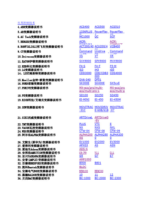
红邦控制技术4.ABB变频器说明书ACS400ACS500ACS5105.AB变频器说明书1336PLUS II PowerFlex 4PowerFlex 406.AC Tech变频器说明书MC1000QC SCF7.BERGES变频器说明书ACM-D2/S2/S3ACM-COMPACT8.BONFIGLIOLI邦飞利变频器说明书ACT200/400ACU200/400VCB4009.CT变频器说明书Command er GP Unidrive SP Command er SE 10.Drivecon变频器说明书XS XT XR 11.EATON伊顿变频器说明书SVX9000SPX9000MVX900012.KEB科比变频器说明书F4-S F4-F F5-M 13.LG变频器说明书iS3iH3iG514、LUST路斯特变频器说明书CDD3000CDE/CDB3000CDS400015.Moeller金钟-默勒变频器说明书DV6-340DF5116.NORD诺德变频器说明书SK300ESK400ESK5xxE17.PDRIVE变频器说明书18.PE变频器说明书SD100SD250SD45019.RICH利佳/艾瑞克变频器说明书EI-MINIEI-450EI-450M20.SEW变频器说明书MOVITRAC -31C MOVIDRIV E-60B/61B MOVITRAC -0721.SIEI西威变频器说明书ARTDriveL ARTDriveG-EV22.TMT变频器说明书PLUS VTC E 23.VACON瓦控变频器说明书NX NXS NXL 24.WEG变频器说明书CTW-04CFW-08CFW-0925.阿尔法ALPHA变频器说明书ALPHA2000G ALPHA2800ALPHA330026.艾默生(原华为)变频器说明书EV1000EV2000EV300027.爱得利变频器说明书APXG3ASASN28.爱迪生Adsen变频器说明书ADS-A29.安邦信AMBITION变频器说明书G9/P9V11G1130.安川YASKAWA变频器说明书G5G7E731.安普(AMPLE)变频器说明书AMP100032.百德福BEDFORD变频器说明书B500B80133.斑科Bantek变频器说明书BLDC34.宝德电气BODE变频器说明书BEM100BEM20035.葆德BALDOR变频器说明书10111236.贝西B&C变频器说明书BC-1000BC-2000BC-2300MX-eco/pro/multi-eco/multi-pro-1MX-eco/pro/m eco/multi-pro-237.传动之星(STAR@DRIVE)变频器说明书SD-5L-G/P/YSD-5L-S SD-7L38.创杰变频器说明书ACT-V6G/P/ZACT-M739.春日(KASUGA)变频器说明书KVFC40.丹佛斯(Danfoss)变频器说明书FC51FC100FC20041.德弗(DOVOL)变频器说明书DV300DV600ST50042.德莱尔变频器说明书DVA DVM DVS43.德力西变频器说明书CDI900044.德瑞斯(DIRISE)变频器说明书DRS1000-M DRS2000DRS280045.东达变频器说明书TDS-F8TDS-V846.东洋(TOYO)变频器说明书VF61R VF6447.东元(TECO)变频器/伺服说明书7300EV7300CV7200MA48.东芝(TOSHIBA)变频器说明书VF-nC1VF-S9VF-S1149.方禾(FangH)变频器说明书TE280F66-B F66-C50.飞兆变频器说明书FG51.佛朗克(FRANCK)变频器说明书FRS2000FRB600052.佛斯特(FIRST)变频器说明书FST-500FST-550FST-60053.富凌(FULING)变频器说明书DZB60J DZB70B DZB200M54.富士(FUJI)变频器说明书FRN-G11S FRN-P11S E1S55.高士达(GOLDSTAR)变频器GS200L56.哥伦(GRET)变频器说明书GD-V557.格立特(GREAT)变频器说明书VF10VF11VF1558.海利普变频器说明书HOLIP-A/F/H/MHOLIP-C HOLIP-P59合康亿盛高压变频器说明书HIVERT通用HIVERT矢量60.泓筌变频器说明书HC1-A HC1-M61.鸿宝(HOSSONI)变频器说明书HB-G9/P9HB280-G HB280-P62.华科(HUANIC)变频器说明书HI3G/F HI9G/F63.华蓝(HLinverter)变频器说明书HL200064.汇川(INOVANCE)(默纳克NICE)变频器说明书MD300MD300A MD32065.汇菱(HUILING)变频器说明书H300066.基创变频器说明书E35067.吉纳变频器说明书MSC-3MFI-Case00/CaseA/CaseB68.加能变频器说明书ACmaster-H7IPC-MD IPC-DR69.佳川(JiaChuan)变频器说明书BP60JCRQ70.佳灵变频器说明书JB6C-T971.金肯(JINKEN)变频器说明书JK-G/P72.九德松益变频器说明书CT-200073.开拓变频器说明书KT-A6G/P74.凯迪华能变频器说明书CD200075.康沃(博世力士乐)变频器说明书S1G2G376.科陆变频器说明书CL1700CL2700CL370077.科姆龙变频器说明书KV1900KV200078.库马克变频器说明书CMK-30079.酷马(QMA)变频器说明书Q7000Q900080.乐邦变频器说明书LB60G LB90G81.乐星产电变频器说明书Starvert82.雷诺尔变频器说明书JJR1000JJR2000JJR500083.力普变频器说明书LP10084.菱科(LINGKE)变频器说明书LK600-G/P/ZSLK80085.隆兴变频器说明书LS200A LS600LS80086.路斯特(LUST)驱动器说明书AD系列CDD系列87.伦茨(Lenze)变频器说明书8200/82108220/8240823088.麦孚变频器说明书VFD-F540VCD100089.麦格米特变频器说明书MV300MV60090.美之源(MZY)变频器说明书MZY-M/Y/Z/T/L91.蒙德(MODROL)变频器说明书IMS-GF IMS-GL2IMS-GL392.米高变频器说明书Micovert2003Micovert34 0N93.明电舍(MEIDEN)变频器说明书VT230S VT230SE VT240S94.南方安华变频器说明书A100E100S10095.能士(NSA)变频器说明书NSA20NSA8096.宁茂(赫力)变频器说明书RM597.欧陆变频器/直流调速器说明书512C590+590P98.欧姆龙(OMRON)变频器说明书3G3JV3G3EV3G3FV99.欧瑞(HFinverter)(原惠丰)变频器说明书F2000-G F3000F1000-G100.派克汉尼汾(parker)变频器说明书AC650AC650V AC690+ 101.派尼尔(Pioneer)变频器说明书VF2100VF3000VF5000 102.普传(POWTRAN)变频器说明书PI97G PI7000/7100PI7500103.群倍(QUNBEI)变频器说明书QLP5000104.日搏变频器说明书RB600RB3000RB5000 105.日锋(RiFeng)变频器说明书RF200RF9000106.日虹变频器说明书CHRH-A CHRH-C CHRH-D 107.日立(HITACHI)变频器说明书SJ100L100SJ200 108.日普(RIPOW)变频器说明书RP3200109.日拓变频器说明书HL3000110.日业(SUNYE)变频器说明书SY3200111.荣信电力电子变频器说明书HVC112.瑞恩(RELIANCE)变频器说明书PSC4000/5000/DDS5000PSC7000VZ3000113.赛普(SAPPHIRE)变频器说明书SAP500G SAP300114.赛普变频器说明书SAP900G SAP300V115.三晶变频器说明书SAJ8000116.三肯(SANKEN)变频器说明书SAMCO-i SAMCO-vm05SAMCO-e117.三菱(MITSUBISHI)变频器说明书A500E500F500 118.三木(MIKI)变频器说明书V6119.三品(SANPIN)变频器说明书SKJ SPRQ-333120.三碁(SANCH)(三川)变频器说明书SA SE121.三星(SAMSUNG)变频器说明书MOSCON-E7MOSCON-F7MOSCON-F500122.森兰(SENLAN)变频器说明书SB50SB60/61SB61Z 123.山宇变频器说明书SY6000SJR2124.珊星变频器说明书F5000F6000125.深川变频器说明书SVF2000SVF3000126.神源(SYRUNS)变频器说明书SY4000SY5000127.施耐德变频器说明书ATV38ATV58-1ATV58-2 128.时代变频器说明书TVF1000TVF3000TVF5000 129.时运捷变频器说明书SuperBona-iF/iPDB-2100130.士林变频器说明书SH系列SS系列SB系列131.世通(EACON)变频器说明书EC1000EC3000EC5000 132.收获(Seoho)变频器说明书SOHO-VD SOHO-SMS133.思达(SD)变频器说明书JPSD3000-G/P/V/H134.斯德博(STOBER)变频器说明书FAS4000FDS4000MDS5000 135.四方变频器说明书C300C320E320 136.松下(PANASONIC)变频器说明书VF0VF0C VF-8Z 137.台安(TAIAN)变频器说明书E2N2V2138.台达(DELTA)变频器说明书VFD-A VFD-B VFD-F 139.台凌(TAILING)变频器说明书TL80TL100TL100H 140.腾龙变频器说明书VG3000-G/H141.天正变频器说明书TVFS9TVFG9/P9TVFG11 142.万谷(WANGU)变频器说明书VF2000143.威尔凯变频器说明书WKF WKS WKR5000 144.威科达变频器说明书V6145.威灵(WELLING)变频器说明书WELLING-G/P/F146.微能变频器说明书WIN-VB WIN-9G WIN-9F 147.韦尔变频器说明书AC30G/P/W/H148.伟创(VEICH)变频器说明书AC20AC32AC60 149.沃森(VicRuns)变频器说明书VSI9000150.西驰变频器说明书CFC1000CFC4000151.西尔康变频器说明书H3000152.西林变频器说明书EH600A EH600M EH600W 153.西门子(SIEMENS)变频器说明书MM410MM420MM430154.现代(HYUNDAI)变频器说明书N50N100N300 155.晓磊(CHXL)变频器说明书LEI2000LEI2005LEI3000 156.信捷(XINJE)变频器说明书V5/F5157.星河(XINHE)变频器说明书SD-5L158.亚泰(YT)变频器说明书YTD-G160.阳冈电子变频器说明书G1/H1/P1E1S1 161.依尔通(Emotron)变频器说明书FDU VFX VSA 162.依托(ESTAR)变频器说明书EG/EF163.亿森变频器说明书参数表164.易能变频器说明书EDS700EDS2860165.易驱变频器说明书ED2003ED2800ED3000 166.意科(IECCO)变频器说明书SINUS-N167.英泰(Invertek DRIVES)变频器说明书OptidrivePlus 3GV OptidrivePlus3GVCompactOptidriveVTC168.英威腾(INVT)变频器说明书CHV100CHV190CHF100 169.鹰垦(INK)变频器说明书SLX170.优利康变频器说明书YD3000YD5000171.尤尼康(UNICON)(原北京兰海)变频器说明书低速大扭矩无码盘有码盘172.誉强(YUQIANG)变频器说明书YQ3000-M YQ3000-A YQ3000-G 173.远川(YCDZ)变频器说明书YC-G YC-P174.正频(JPS)变频器说明书PDS PDA/H/E175.正泰(CHINT)变频器说明书NI01176.正弦(SINEE)变频器说明书SINE300SINE303SINE307 177.正阳(Zhengyang)变频器说明书ZY29/31/98ZY-812178.中源(ZYDL)变频器说明书ZY-G800ZY-G800E ZY-A900 179.中远变频器说明书MF6MF5/20MF30 180.珠峰变频器说明书DLT-G11/P11/Z181.住友(SUMITOMO)变频器说明书HF320SF320HF430 182.紫日(CHZIRI)变频器说明书ZVF7ZVF9ZVF9V 183.南海华腾(V-T)变频器说明书V5-H E5-P V6-HACS600ACS800ACS1000PowerFlex 400PowerFlex 70PowerFlex 700SE1SW1SYN10S/T SPL200/400VF5100HG VF51RG VFDBVF61CVF61VF64VFK1/VFN 1GVX9000F5-M/S iS5iHSK530E SK700E SK750ESD700EI-500EI-550EI-600EI-700EI-7001EI-8001EI Super NMOVIRET-315/328/355/380/3150IP55 PLUS IP55 E CFW-10CFW-11EV3100EV3500TD900TD1000TD2000TD3000TD3100MSE11Z9/Z11F7J7V7PC3P5/PC514ro/multi-co/multi-pro-2FC300VLT2000VLT2800VLT2900VLT3000VLT5000 HL2000DV1000DRS30007200GA7300PA7200GSVF-A5VF-A7VF-AS1DZB300BF1S FRN-FVR-E11SMini/C1SHB280-ZMD330ME280NICE3000IPC-RF9300Vector690+590C3G3HV3G3MV3G3RVF1500-GPI7600/78PI766000SJ300SJ300-EL L200L300P VZ7000MF/MS ES/ET/EF IHF/IPF SHF/SPFS500A700E700F700D700 SB70SB100SB200BT40ATV61ATV68-1ATV68-2ATV68-3SDS4000E350E380E520H320M1X M2XVF100DV700/707SV300N310S310EV300VFD-G VFD-M VFD-S VFD-VWIN-9I WIN-9LAC61-Z AC62-LEH600ZMM4406RA706SE70J300TOPVERT TOPVERT TOPVERTVSC CDX CDU MSF ED300S ED3100Optidrive E OptidriveE1OptidriveE2OptidriveMEMA 4XSINE308SINE309 ZY-P800ZVF11VFN2TD3200TD3300。
ABB-ACS500变频器参数设置

0
212
模拟输出通道1调幅
4095
4095
213
模拟输出通道2调零
0
0
214
模拟输出通道2调幅
4095
4095
215
模拟输出通道3调零
0
0
216
模拟输出通道3调幅
4095
4095
217
模拟输出通道4调零
0
0
218
模拟输出通道4调幅
4095
4095
219
模拟输入1断线保护底阈值
323
323
220
模拟输入1断线保护顶阈值
74
开机起始运行频率
100
100
75
拐点频率
5000
5000
76
最低工作频率
100
100
77
最大运行频率
5000
5000
78
频率跳跃点1
5300
5300
79
频率跳跃点2
5300
5300
80
频率跳跃点3
5300
5300
81
频率跳跃点1的跳跃范围
0
0
82
频率跳跃点2的跳跃范围
0
0
83
频率跳跃点3的跳跃范围
0
0
84
给定频率阈值
30
30
85
数字量输入的频率给定1
3000
3000
86
数字量输入的频率给定2
4000
4000
87
数字量输入的频率给定3
5000
5000
88
额定过载倍数
120
120
500-S安装使用说明书

500S可燃气体探测器安装使用说明书中美合资无锡梅思安安全设备有限公司WUXI MSA SAFETY EQUIPMENT CO.,LTD.目录一、概述: (2)二、工作原理: (2)三、性能特点: (2)四、技术参数: (2)五、安装 (3)六、日常标定与调整 (4)七、维护 (5)八、探测器标定箱 (6)一、概述:500S点型可燃气体探测器的探头系美国原装进口,可连续检测空气中的可燃性气体和可燃性蒸汽的浓度(最低爆炸下限的浓度)。
广泛适用于石化、钢铁、化学、采矿、电子、建筑、电信等行业。
二、工作原理:500S点型可燃气体探测器安装了一个接触反应式的催化燃烧探头。
探头由一个活化的灯丝(检测用)和钝化的灯丝(补偿用)组成。
可燃气体或蒸汽-空气混合物通过扩散到达灯丝处,气体会在检测灯丝上进行无焰燃烧,这就改变了灯丝上的温度和电阻,造成电桥的不平衡,而电桥的输出信号和气体的浓度成正比,这个信号就可被送到可燃气体报警控制器,进行处理。
三、性能特点:⏹不锈钢制造,耐腐蚀,配套防雨罩,抗雨淋水袭;⏹探头原装进口,零点稳定,可靠耐用,典型寿命≥3年;⏹扩散式采样,抗高浓度可燃气体及蒸汽的冲击;⏹与同类产品相比,具有较强的抗卤化物能力;⏹可配套本公司的可燃气体报警控制器。
四、技术参数:工作温度:-40℃~70℃工作湿度:≤90% RH测量范围:0 ~100%LEL测量精度:±5% LEL防爆等级:ExdⅡCT6(硝酸乙脂除外)防护等级:IP65外型尺寸:长×宽×高(mm):196×178×66重量: 2.5公斤响应时间:达到90%稳定值≤30秒探头电流:372mA (1S抗中毒灯丝)传输电缆:1)RVVP4×1.5mm2 (传输距离≤750m)2)RVVP4×2.5mm2(750m≤传输距离≤1500m)五、安装探测器的防爆等级为dⅡCT6,可安装在1级危险场所。
Хоefеr PS 500 XT电离仪操作登记表 说明书

r manualElectrophoresis Systems, Standards and Reagents500XTPSDC power supplyc on ont t e n t s1Operating Instructions . . . . . . . . . . . . . . . . . . . . . . . . . . . . . . . . . 1 Constant current mode . . . . . . . . . . . . . . . . . . . . . . . . . . . . 1 Constant voltage mode . . . . . . . . . . . . . . . . . . . . . . . . . . . . 1 Constant current to constant voltage . . . . . . . . . . . . . . . . . . 1 Constant voltage to constant current . . . . . . . . . . . . . . . . . . 2 2Troubleshooting . . . . . . . . . . . . . . . . . . . . . . . . . . . . . . . . . . . . . 2 3Maintenance . . . . . . . . . . . . . . . . . . . . . . . . . . . . . . . . . . . . . . . . 3 Cleaning . . . . . . . . . . . . . . . . . . . . . . . . . . . . . . . . . . . . . . 3 Replacing Fuses . . . . . . . . . . . . . . . . . . . . . . . . . . . . . . . . 3 Output fuse . . . . . . . . . . . . . . . . . . . . . . . . . . . . . . . . . . . . . . .3Input Fuses . . . . . . . . . . . . . . . . . . . . . . . . . . . . . . . . . . . . . . .4 A Specifications . . . . . . . . . . . . . . . . . . . . . . . . . . . . . . . . . . . . . . . 5Ordering Information. . . . . . . . . . . . . . . . . . . . . . . . . . . . . . . . . . . 6 Technical Service and Repair . . . . . . . . . . . . . . . . . . . . . . . 6 Important repacking instructions . . . . . . . . . . . . . . . . . . . . . . . .6Safety InformationThe PS 500XT power supply must be plugged into a properly grounded 3-wire power outlet for your safety.All loads powered by the supply must be connected before turning on the power supply. Both the positive and negative leads from the load(s) must be connected. Failure to connect one lead could cause a safety hazard.Turn the power supply off before disconnecting the leads.O p e r a t i n g I n s t r u c t i o n s 1Operating InstructionsSet the 4 sets of output jacks on the PS 500XT to supply either constant voltage or constant current power. The voltage reading is the same across all sets of jacks; the current reading is the sum of the loads connected to all sets of jacks. If the loads are of differing resistance, you may briefly connect each load singly to check what current it pulls; otherwise the current reading is divided equally among them.Use the dial on the front panel to set the 7-hour time. For operation longer than 7hours, set the dial to the ON HOLD position.Constant current mode1.Plug the power cord into the mains power module in the back of the unit andinto a properly grounded 3-wire power outlet.2.Connect the load(s).3.Turn the current adjust knob fully counter-clockwise.4.Turn the voltage adjust knob fully clockwise.5.Turn on the mains power switch and set the timer.6.Turn the current adjust knob to the desired value, as displayed on the LEDammeter. The current is now set to remain constant while the voltagechanges in response to load requirements.Constant voltage mode1.Plug the power cord into the mains power module in the back of the unit andinto a properly grounded 3-wire power outlet.2.Connect the load(s).3.Turn the voltage adjust knob fully counter-clockwise.4.Turn the current adjust knob fully clockwise.5.Turn on both the mains power switch and set the timer.6.Turn the voltage adjust knob to the desired value, displayed on the LEDvoltmeter. The voltage is now set to remain constant across the load while the current changes to meet load requirements.Constant current to constant voltage1.Plug the power cord into the mains power module in the back of the unit andinto a properly grounded 3-wire power outlet.2.To start a run set for constant current with a voltage ceiling, first turn on thepower supply with no load attached.3.Turn the current adjust knob slightly and then set the maximum desiredvoltage with the voltage adjust knob.4.Turn the power off and connect the load.T r o u b l e s h o o t i n g5.Turn the power back on.6.Set the desired current with the current adjust knob. Do not adjust thevoltage adjust knob.Constant voltage to constant current1.Plug the power cord into the mains power module in the back of the unit andinto a properly grounded 3-wire power outlet.2.Turn on the power supply with the load attached.3.Turn the voltage adjust knob fully clockwise and then turn the current adjustknob to the desired maximum current setting.4.Then turn the voltage adjust knob so that the desired starting voltage isdisplayed.2TroubleshootingProblem Probable Cause RemedyNo display No power to circuits.Check that the supply isplugged into a workingpower outlet.Make sure both the rearpower switch and timerare on.Check input fuses. SeeMaintenance section.No output but displays are lit and limits are set correctly Power supply failure.Call an AmershamPharmacia BiotechService representative.3MaintenanceCleaningTurn off and unplug the power supply before cleaning. The cabinet and displaymay be cleaned with a mild cleaning solution and a soft cloth.Important Do not set liquid containers on top of the power supply. Do not pour liquids on or near the supply.If substances are spilled on or near the power supply, unplug the unit immediatelyand move it away from the spill. Dry off the power supply with a soft cloth orpaper towel. If liquid has been spilled inside the supply, unplug it and allow it tosit for five minutes. Then remove the cover and blot up any standing liquid.Allow the unit to air dry for several hours.Important If it appears that a spill has leaked onto the circuit boards, call an Amersham Pharmacia Biotech service representative before attempting to operate the unit.Replacing FusesThe fuses in the mains power module in the back of the unit do not requiremaintenance, but may fail due to fatigue under normal operating conditions.Fuses protect equipment by disconnecting loads too large for the instrument'scircuit design, so it is imperative that fuses are replaced only by identical fusetypes.Output fuse115 V AC model - one 0.5 A, 250 V, Fast Blo, 5 x 20 mm230 V AC model - one 0.5 A, 250 V, Fast Blo, 5 x 20 mmImportant Turn off the power supply and detach the power cord before replacing fuses.e a small flat blade screwdriver to push in the fuse cap and rotate it 1/4turn counter-clockwise.2.Insert the new fuse into the fuse cap and push it back into the fuse holder.Rotate the fuse cap 1/4 turn clockwise to lock it into position.Input Fuses115 V AC models - two 5 A fuses, 250 V, Slo Blo, 5 x 20 mm230 V AC models - two 2.5 A fuses, 250 V, Slo Blo, 5 x 20 mmFig3-1 illustrates how to replace the mains power module fuses.Fig 3-1Changing mains power module fusesImportant Turn the mains power supply switch off and detach the power cord before replacing input fuses!1.Open the fuse compartment by inserting a small flat-blade screwdriver intothe slot at the left side of the power module. Twist the screwdriver 1/8-turnto re-lease the cover, then pull out the hinged compartment, which opens tothe right.2.Insert the screwdriver above the arrow on one fuse cassette, catch thecassette end, and slowly slide it completely out of the module.3.Pull the fuse out of its cassette and inspect.If the fuse element is burned or broken, replace the fuse with an identicaltype. If the fuse appears to be intact, check it with an ohmmeter. A shortcircuit indicates the fuse is still usable.4.After placing a good fuse into the cassette, slide it into the power module,making sure the arrow on the cassette points to the right, the same directionas the guide arrows on the inside of the compartment door.5.Repeat steps 2 - 4 for second cassette.6.Close the fuse compartment cover and gently press it into the power moduleuntil it snaps shut.7.Plug unit in and turn mains power switch on.S p e c i f i c a t i o n sAppendix A SpecificationsMains power115 VAC 230 VAC ±10%, 60 Hz ±10%, 50 HzFuses (All fuses are 250 V)115 VAC 230 VAC Input: 5.0 A, Slo Blo, 5 x 20 mm (2) Output: 0.5 A, Fast Blo, 5 x 20 mm Input: 2.5 A, Slo Blo, 5 x 20 mm (2) Output: 0.5 A, Fast Blo, 5 x 20 mmPower supply 0 to 500 V DC constant voltage at0 to 400 mA DC constant current0 to 200 W DC powerLoad regulation V - <1.0% at 0-100% full loadI - <1.0% at 100% load change Ripple and noise250 mV RMS290µA RMSLine regulation <1%, ±10% line voltageOperating temperature0–40 °CSafety Certified to comply with UL 1244 andIEC 1010-1 safety standards.O r d e r i n g I n f o r m a t i o nOrdering InformationTechnical Service and RepairAmersham Pharmacia Biotech offers complete technical support for all our products. If you have any questions about how to use this product, or would like to arrange to repair it, please call or fax your local Amersham Pharmacia Biotech representative.Important repacking instructions Request a copy of the Amersham Pharmacia Biotech “Contamination Clearance Certificate” before returning the item. No items can be accepted for servicing or return unless this form is properly completed.Amersham Pharmacia Biotech UK Limited Amersham Place Little Chalfont Bucks HP7 9NA England Amersham Pharmacia Biotech AB SE-751 84 Uppsala Sweden Amersham Pharmacia Biotech Inc 800 Centennial Avenue PO Box 1327 Piscataway NJ 08855 USA Amersham Pharmacia Biotech Europe GmbH Postfach 5480 9 D-79021 Freiburg Hoefer is a trademark of Amersham Pharmacia Biotech Limited or its subsidiaries.Amersham is a trademark of Nycomed Amersham plc Pharmacia and Drop Design are trademarks of Pharmacia and Upjohn Inc.All goods and services are sold subject to the terms and conditions of sale of the company within the Amersham Pharmacia Biotech group which supplies them. A copy of these terms and conditions is available on request.© Amersham Pharmacia Biotech 1999—All rights reserved.Qty.Code No.PS 500XT DC Power Supply with 7-hour timer and four dual output jacks, 0-500 V DC, 400 mA. Can be set to constant voltage or constant current with automatic crossover. 115V , 60 Hz 230V , 50 Hz. 1180-6102-9980-6103-18Power cord (115 V) 180-6106-03Power cord (230 V) 180-6230-10Output fuses 250 V , 0.5 A, Fast Blo, 5 x 20 mm (5/pkg) 1 pkg 80-6335-74Input fuses for 115 VAC model 250 V , 5 A, Slo Blo, 5 x 20 mm (5/pkg) 1 pkg 80-6112-30Input fuses for 230 VAC model 250 V , 2.5 A, Slo Blo, 5 x 20 mm (5/pkg) 1 pkg 80-6110-21Printed in USA。
ABB变频器使用说明书

一、环境条件⏹防护等级IP21/UL 1: 这个等级规定安装现场无粉尘, 无腐蚀性气体或液体, 无导电性颗粒物, 例如凝露、碳粉或小金属颗粒。
IP54/UL 12: 这个等级可以提供对气体粉尘以及各个方向的轻度溅水的保护。
•与IP21/UL 1 的防护等级相比, IP54/UL 12防护等级具有以下特点:•与IP21/UL 1 的防护等级相同的内部塑料罩。
•不同的出风口侧塑料盖板。
•附加一个内部风扇以改善冷却。
•更大的外部尺寸。
•同样的容量(不需要降容使用)。
⏹环境条件• 1.海拔高度•海拔高度在0~1000米时, 输出电流=I2N 额定电流海拔高度在1000~2023米时, 每升高100米则PN和I2N 降容1%。
假如安装地点海拔高度高于2023米, 请联系本地的ABB变频器。
• 2.环境温度•最低温度-15℃-不允许有结霜。
•最高温度(fsw=1或4KHZ)为40℃。
fsw指开关频率•假如PN和I2N 降容到90%时, 允许温度为50℃.•假如PN和I2N 降容到80%时, 允许最高温度(fsw=8KHZ)为40℃。
•假如PN和I2N 降容到65%时, 允许最高温度(fsw=12KHZ)为30℃.温度在40~50℃之间, 温度高于40℃时(fsw=4KHZ)每增长1℃, 额定输出电流减少1%。
实际输出电流要乘以降容因子例如:假如环境温度是50℃, 那么降容因子为100%-1%/℃x10℃=90%或0.90则输出电流为0.90 xI2N 。
•3.相对湿度•小于95%(不允许结露)•4.污染级别•不允许有导电性粉尘存在。
•ACS510应根据外壳防护等级安装在清洁的通风环境中。
•冷却空气必须是清洁的, 无腐蚀性气体和无导电性粉尘。
•化学气体: Class 3C2固体颗粒: Class 3S2二、基本型控制盘使用三、参数设立Group 99:启动数据•此参数组专门用于配置:•设立变频器•输入电机数据Group 01:运营数据这些参数涉及了变频器装置的运营数据, 涉及实际信号。
S7200Smart如何与ABBACS550进行Modbus通讯

S7-200Smart如何与ABB-ACS550进行Modbus通讯现在来介绍一下S7 200Smart如何与ABB ACS550进行Modbus通讯,在这里我使用了S7 200Smart库中的Modbus主站通讯程序。
具体步骤如下:1. ABB ACS 550变频器设置:9802=1 MODBUS5302=3 站号5303=9.6kbit/s 波特率5304=0 无校验5305为0 ABB DRV LIM(ABB传动简装版)1001=10 启/停和方向信号来自现场总线(由MODBUS控制变频器启停)1102=0 选择外部控制11103=8 给定值来自串行通讯2. 在STEP 7-MicroWIN SMART软件中编写程序。
(如图)3. 下载并调试程序。
程序编写完成后,使用SMART 200CPU自带的以太网口进行下载至CPU中。
并将CPU切换至运行状态。
通过STEP 7-MicroWIN SMART软件中的状态图表来进行在线修改变量,从而达到启、停和改变变频器的转速,或监控变频器的实际频率与电流等。
变频器参数设定完成后,给变频器断电,接好SMART 200CPU与变频器之间的串行通讯电缆,并重新启动变频器,记住不要忘了将变频器的控制模式切换远程控制模式下。
打开STEP 7-MicroWIN SMART软件中的状态图表,输入需要监控的变量。
在程序中使用了VB300来监控变频器0XXXX寄存器中的控制字,在说明书中已明确了该寄存器中的控制字为只读(除非使用了强制功),因此使用读功能来读取,读取方式为字节,如V300.0,V300.1…;同样我们可以读取1XXXX寄存器中的状态字。
(如图)启动变频器:在ABB ACS550变频器的手册中,已定义了变频器的控制字是直接映射到了4XXXX寄存器中的40001(在本程序中对应CPU中的存贮区为VW500),是以字节的形式读写的(以十六进制存格式保存);4XXXX寄存器中的40002(在本程序中对应CPU中的存贮区为VW502)为外部控制1,同样也是以字节的形式读写的。
- 1、下载文档前请自行甄别文档内容的完整性,平台不提供额外的编辑、内容补充、找答案等附加服务。
- 2、"仅部分预览"的文档,不可在线预览部分如存在完整性等问题,可反馈申请退款(可完整预览的文档不适用该条件!)。
- 3、如文档侵犯您的权益,请联系客服反馈,我们会尽快为您处理(人工客服工作时间:9:00-18:30)。
编 校 审 批
写 对 核 准 _________
南京南瑞集团公司水利水电技术分公司 2012 年 08 月 26 日
NARI
ACS500 数据采集器 使用说明书 V1.0
南京南瑞集团公司
NARI
使用说明书
前言
前言
简介
本手册为用于介绍 ACS500 数据采集器的使用方法和注意事项。适用读者为 相关用户。
提示和警告
本手册中采用了以下几种图标,其含义分别如下。 可能造成设备永久性损坏情况的警告 有助于正确使用产品的相关信息 有助于理解产品工作方式的举例 产品维护技巧
- II -
NARI
使用说明书 文件修订记录
文件修订记录
序号 1 修订日期 2012-8-26 修订内容 初版 版次 V1.0
i
ii
NARI
............................................................................................................................................ I 简介........................................................................................................................................... I 版权所有©................................................................................................................................ I 商标声明................................................................................................................................... I 注意! ......................................................................................................................................... I 无担保声明.............................................................................................................................. II 提示和警告.............................................................................................................................. II 目录 ................................................................................................................................................. A 第一章 概述..................................................................................................................................... 1 1.1 用途.................................................................................................................................... 1 1.2 功能.................................................................................................................................... 1 1.3 特点.................................................................................................................................... 1 1.4 技术参数............................................................................................................................ 2 1.4.1 电气参数......................................................................................................................... 2 1.4.2 传感接口................................................................................................................. 2 1.4.3 其它接口................................................................................................................. 2 1.4.4 存储容量................................................................................................................. 2 1.4.5 通信接口................................................................................................................. 2 1.4.6 时钟参数................................................................................................................. 3 1.4.7 工作环境条件......................................................................................................... 3 1.4.8 其它参数................................................................................................................. 3 第二章 硬件接口及接线................................................................................................................. 5 2.1 外观.................................................................................................................................... 5 2.2 电源接口............................................................................................................................ 5 2.2.1 供电电源接口......................................................................................................... 5 2.2.2 浮充电源接口......................................................................................................... 6 2.3 传感器接口........................................................................................................................ 6 2.3.1 传感器电源接口..................................................................................................... 7 2.3.2 雨量计接口............................................................................................................. 7 2.3.3 SDI-12 接口 .............................................................................................................. 8 2.3.4 RS485 接口............................................................................................................... 9 2.3.5 其他传感器接口................................................................................................... 10 2.4 通信接口.......................................................................................................................... 10 2.5 指示灯.............................................................................................................................. 11 2.6 TEST 按键 ........................................................................................................................ 12 2.6.1 远程测试功能....................................................................................................... 12 2.6.2 调试功能................................................................................................................ 12 2.7 SD 卡接口 ........................................................................................................................ 12 2.8 继电器开出口.................................................................................................................. 13 2.9 箱门状态接口.................................................................................................................. 13
