库柏(cooper)离心式压缩机手册
TA3000中文手册
第一章简介 TA3000中文手册在本章使用者将学到如下内容:※库柏压缩机※ TA3000离心式压缩机※安全预防※安全标识※保修期※责任范围※无授权之维修库柏压缩机简介:作为世界领先水平的离心式压缩设计和制造者,Cooper压缩有着超过四十年的技术传统。
此种技术领先和革新起始于1955年,在那时此公司的前身JOY 生产了第一台整体齿轮增速式离心式压缩机,随着JOY的成长最后发展成为Cooper压缩机。
在早些年发展起来的原始技术成为创造性设计的标准,也将继续成为无油离心式压缩机的定义标准。
其可靠、有效和可调的生产线使Cooper压缩机成为在高技术离心式压缩机生产的全球领先者。
从最初的MSG G8系列到改进的TA2000和TA3000,都是从简易的自动化和高的运行可靠性而著称。
Cooper 离心式压缩机现已遍布全球六大洲。
随着国际社会对清洁环境的关心,这促使用户选择使用Cooper压缩机产品,可以让用户以无油压缩空气作为动力的同时减少所需的能源消耗。
美国纽约州Buffalo包括本部、制造工场领先成为研究和发展设施及培训机构。
这些资源再加上遍布全球的分销商和经过培训和授权的服务人员使得Cooper压缩机有限公司能够提供给那些使用Cooper 离心式压缩机用户最好的产品和服务。
Cooper压缩机公司通过了ISO9001认证。
要了解更多的信息请参观我们的网站:。
TA3000离心式压缩机:TA3000离心式压缩机是符合用户需求的具有先进水平生产无油压缩机空气其简捷而可靠的设计使其具有许多优点。
其设计中包含了最好的空气动力学技术以达到最佳的能效。
其单位流量所消耗的功比其它无油离心式压缩所消耗的功要低。
使用最先进的压缩机元件:TA3000压缩机内部使用了工业界独一无二的元件。
优良的小齿轮轴承设计使其在任何载荷下具有无限的使用寿命,非接触式、非磨损型油封不需要阻油空气就能保证无油压缩空气。
叶轮设计采用了Sigma—radial和后倾式叶轮的优点,与叶轮相对应的扩压器具有非常高的效率。
卡麦龙(库伯)产品介绍
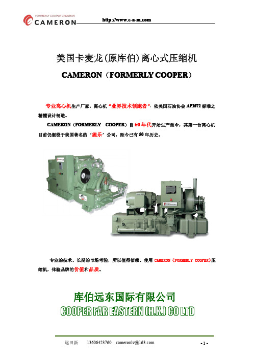
美国卡麦龙(原库伯)离心式压缩机CAMERON(FORMERLY COOPER)专业离心机生产厂家,离心机“业界技术领跑者”,依美国石油协会API672标准之精髓设计制造。
CAMERON(FORMERLY COOPER)自50年代开始生产至今,其第一台离心机目前仍服役于美国著名的‘施乐’公司,距今已有50年历史。
专业的技术、长期的市场考验,所以值得信赖。
使用CAMERON(FORMERLY COOPER)压缩机,体验品牌的价值和品质。
在美国纽约证券交易所挂牌的卡麦龙集团(Cameeron)(股票代号:CAM),是在石油、天然气、工业设备和相关服务方面具有全球领先地位的大型跨国企业,遍布全球的一万五千多名员工,为客户提供优质的产品和服务。
Cameron集团在世界各地都有业务,2/3的收入来自大约115个国家,几乎包括全世界每一个主要石油产地。
公司的工厂和服务中心遍及美国、加拿大、墨西哥、委内瑞拉、巴西、阿根廷、英国、挪威、荷兰、爱尔兰、法国、德国、奥地利、阿塞拜疆、哈萨克、尼加拉瓜、埃及、阿联酋、阿曼、巴基斯坦、新加坡、澳大利亚等。
分为三大部门油气开采和生产部主要为陆地和海洋钻采和生产提供各种钻采设备、流体控制系统、油气分离和处理系统,如防井喷器等。
1995年由Cooper Industry Company的一个部门形成。
下设3个子部门Cameron Controls,Cameron Actuators和Cameron Willis。
主要生产:陆上井口,陆上钻井,海上井口,海上钻井,闸阀,截断阀,防喷器,水下采油树,并负责整个系统的集成及检测服务。
防喷器等井控设备制造基地设在美国的休斯敦、Bervick和法国的Bezier。
Cameron为全球用户提供Camserv品牌的全面的卓越的售后服务体系,使每个用户可以放心使用Cameron的产品并得到及时满意的全天候24小时服务。
阀门和计量部致力于石油、天然气、能源以及冶金领域流体控制设备,始终保持着业界先驱的地位和行业最具竞争力的企业。
离心式压缩机原理教程

离心式压缩机原理教程§1 离心式压缩机的结构及应用排气压力超过34.3×10⁴N/m2以上的气体机械为压缩机。
压缩机分为容积式和透平式两大类,后者是属于叶片式旋转机械,又分为离心式和轴流式两种。
透平式主要应用于低中压力,大流量场合。
离心式压缩机用途很广。
例如石油化学工业中,合成氨化肥生产中的氮,氢气体的离心压缩机,炼油和石化工业中普遍使用各种压缩机,天然气输送和制冷等场合的各种压缩机。
在动力工程中,离心式压缩机主要用于小功率的燃气轮机,内燃机增压以及动力风源等。
离心压缩机的结构如图8-1所示。
高压的离心压缩机由多级组成,为了减少后级的压缩功,还需要中间冷却,其主要可分为转子和定子两大部分。
分述如下:1.转子。
转子由主轴、叶轮、平衡盘、推力盘、联轴器等主要部件组成。
2.定子。
由机壳、扩压器、弯道、回流器、轴承和蜗壳等组成。
图8-1 离心式压缩机纵剖面结构图(1:吸气室 2:叶轮 3:扩压器 4:弯道 5:回流器 6:涡室 7,8:密封 9:隔板密封10:轮盖密封11: 平衡盘12:推力盘 13:联轴节 14:卡环 15:主轴 16:机壳 17:轴承 18:推力轴承 19:隔板 20:导流叶片 )§2 离心式压缩机的基本方程一、欧拉方程离心式压缩机制的流动是很复杂的,是三元,周期性不稳定的流动。
我们在讲述基本方程一般采用如下的简化,即假设流动沿流道的每一个截面,气动参数是相同的,用平均值表示,这就是用一元流动来处理,同时平均后,认为气体流动时稳定的流动。
根据动量矩定理可以得到叶轮机械的欧拉方程,它表示叶轮的机械功能变成气体的能量,如果按每单位质量的气体计算,用表示,称为单位质量气体的理论能量:(8-1)式中和分别为气体绝对速度的周向分量,和叶轮的周向牵连速度,下标1和2分别表示进出口。
利用速度三角形可以得到欧拉方程的另一种形式:(8-2)二、能量方程离心式压缩机对于每单位质量气体所消耗的总功,可以认为是由叶轮对气体做功,内漏气损失和轮组损失所组成的。
COOPER产品系列
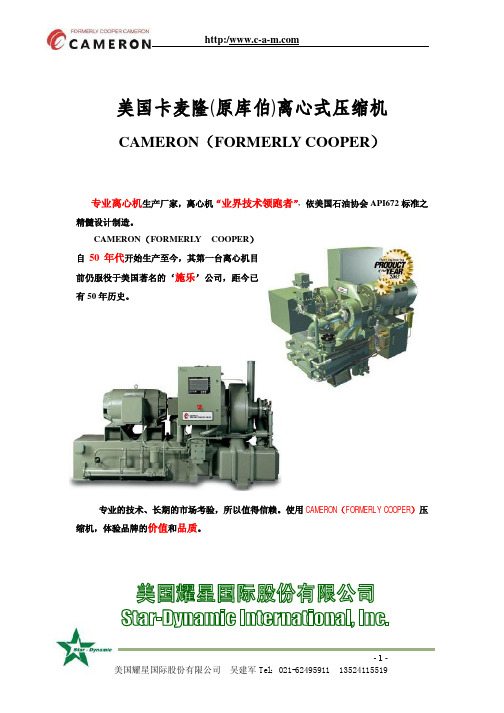
http:/美国卡麦隆(原库伯)离心式压缩机CAMERON(FORMERLY COOPER)专业离心机生产厂家,离心机“业界技术领跑者” ,依美国石油协会 API672 标准之精髓设计制造。
CAMERON(FORMERLY COOPER)自 50 年代开始生产至今,其第一台离心机目 前仍服役于美国著名的‘施乐’公司,距今已 有 50 年历史。
专业的技术、长期的市场考验,所以值得信赖。
使用 CAMERON(FORMERLY COOPER)压 缩机,体验品牌的价值和品质。
-1美国耀星国际股份有限公司 吴建军 Tel:021-******** 135********http:/一. CAMERON(FORMERLY 户的产品已逾 2000 台/套。
二. CAMERON(FORMERLY 等行业。
产品系列包括: 1. TA2000 系列COOPER)压缩机品牌的前身为 JOY。
其专业设计与制造离心式压缩机已有 50 余年的历史。
为全球用户提供了大量的离心式压缩机,仅销给国内用COOPER)之离心机被公认为世界上最好的离心式压缩机之一,广泛应用于空分、钢铁、石化、化工、纺织、制药、发电、汽车、玻璃、电子、造纸气 量:14 m/min 至 55 m/min 排 压:3Bar (表) 至 15Bar (表)2.TA2000 风 冷 系 列 气 量:15.5 m/min 至 50 m/min 排 压:3.5Bar (表) 至 10Bar (表) 电机功率:110~260 kW-2美国耀星国际股份有限公司 吴建军 Tel:021-******** 135********http:/3.TA2020 系 列 气 量:28 m/min 至 60 m/min 排 压:3.5Bar (表) 至 8.6Bar (表)4.TA3000 系列 气 量:56 m/min 至 120 m/min 排 压:3Bar (表) 至 15Bar (表)5.TA6000 系列 气 量:114 m/min 至 250 m/min 排 压:3Bar (表) 至 15Bar (表)-3美国耀星国际股份有限公司 吴建军 Tel:021-******** 135********http:/5.TA9000 系 列: 气 量:184 m/min 至 350 m/min 排 压:3.5Bar (表) 至 15Bar (表)6.TA11000 系列 气 量:212 m/min 至 400 m/min 排 压:3Bar (表) 至 25Bar (表)-4美国耀星国际股份有限公司 吴建军 Tel:021-******** 135********http:/7.TWINTURBO 双排气压力组合机系列 气 量: 排 压: m/min 至 Bar (表) 至 m/min Bar (表)8.TA2040 小流量高压力系列 气 量: 40m/min 至 50m/min 排 压: Bar (表) 至 42Bar (表)-5美国耀星国际股份有限公司 吴建军 Tel:021-******** 135********http:/9.TA 系列 气 量:35 m/min 至 800 m/min 排 压:1Bar (表) 至 70Bar (表) 机器规格:TA26 TA70 TA85 TA200A 等 TA30 TA35 TA35A TA40 TA120 TA50 TA55 TA55A TA60 TA200 TA100 TA100A TA110 TA120A TA16010.MSG 系列 气 量:35 m/min 至 5000 m/min 排 压:2Bar (表) 至 85Bar (表) 机器规格:MSG6 MSG14 MSG7 MSG7A MSG8 MSG9 MSG9A MSG12 MSG14 MSG25 等 MSG16 MSG20-6美国耀星国际股份有限公司 吴建军 Tel:021-******** 135********http:/11.Fuel Gas Booster 工艺气体离心压缩机系列 适用介质: 甲烷等燃料气类、烃烯类、氨类、一氧化碳、二氧化碳、合成气、低分子 量富气、氮气等。
离心式压缩机培训教材
19
离心式压缩机的结构、原理
扩压器
气体从叶轮流出时的速度很高,为了充 分利用这部分速度能,在叶轮后设置流 通截面逐渐扩大的扩压器,以便将速度 能转变为压力能。
20
离心式压缩机的结构、原理
回流器
34
离心式压缩机的结构、原理
防止喘振的措施 由于喘振的危害性很大,压缩机在运行中应
严格防止发生喘振,防止喘振的措施有以下几 条,供参考。 (1)压缩机应备有标明喘振界限的性能曲线。 为安全考虑应在喘振线的流量大出5-10%的 位置上加一条防喘振警戒线,以提醒操作者的 注意。最好设置测量与显示系统,用屏幕显示 工况点的位置,严加注意工况点接近喘振线。
30
离心式压缩机的结构、原理
离心式压缩机工作原理 离心式压缩机与离心泵在工作原理和结 构形式等方面具有很多相似之处,两者 不同之处是输送气体和液体介质性质的 区别和流速大小的差别。离心式压缩机 高速旋转的叶轮带动气体,获得极高的 速度,进入扩压器时,速度降低,压力 升高,然后将增压后的气体输出机外
(5)操作者应了解压缩机的性能曲线, 熟悉各监测系统和控制调节系统的管理 和操作,尽量使压缩机不进入喘振状态。
37
汽轮机部分
38
汽轮机的结构及工作原理
汽轮机的特点 汽轮机的转速可在一定的范围内变动,
增加了调节手段和操作的灵活性;适用 输送易燃易爆的气体,即使泄漏也不易 引起事故;蒸汽的来源比较稳定。与其 它原动机相比,汽轮机具有单机功率大、 效率高、运行安全可靠、使用寿命长等 优点。
32
离心式压缩机的结构、原理
33
离心式压缩机的结构、原理
库珀 10-300 型 冷冻压缩机 技术手册说明书
COMMERCIAL REFRIGERATION COMPRESSORS180****1700************************/IndiaEmerson and Copeland are trademarks of Emerson Electric Co. or one of its affiliated companies. ©2018 Emerson Climate Technologies Inc. All rights reserved.A S I A 10-B 0303-R 01-07/2018REGISTERED HEAD OFFICEEmerson Climate Technologies (India) Pvt. Ltd.Plot No. 23, Rajiv Gandhi Infotech Park, Phase - II, Hinjewadi, Pune-411 057Tel: (91-20) 4200 2000MumbaiEmerson Climate Technologies (India) Ltd.Delphi B-Wing, 601-602, th 6Floor, Central Avenue,Hiranandani Business Park, Powai,Mumbai- 400076Tel: (91-22) 6662 0566Pvt. SecunderabadEmerson Climate Technologies (India) Ltd.C/o Maruthi Corporate Point,nd Swapnalok Complex 2 Floor, Block -B , Sarojinidevi Road, Secunderabad-500003 Tel: (91-40) 3315 4018Pvt. SALES OFFICES:GurgaonEmerson Climate Technologies (India) Private Ltd.th 18 Floor, Tower B, Building No. 5,Epitome, DLF Cyber City,Phase - III, Gurgaon 120 002Tel: (91-124) 489 4500CONTACTS LISTEmerson Commercial & Residential Solutions SecunderabadEmerson Climate Technologies (India) Pvt. Ltd.C/o: Agility Logistics Pvt. Ltd, # 8-122,Devaryamjal Road, Kompally, Shameerpet Mandal, Ranga Reddy Dist.,Secunderabad-500014,Tel: (91) 9247000174/9000649871ChandigarhEmerson Climate Technologies (India) Pvt. Ltd. C/O Agility Logistics Pvt LtdKhata No-694/712 Village–Pabhat MC Zirakpur, District – SAS Nagar Mohali, Punjab-140603Tel: 8054001380HowrahEmerson Climate Technologies (India) Ltd.C/o Agility Logistics Pvt. Ltd., Sankrail Industrial PARK,Mauza-Kandua, Bhagabatipur, Po-Kandua Howrah-711 302 Tel: +919093970556Pvt. New DelhiEmerson Climate Technologies (India) Ltd.56, Rama Road Industrial Area,Nr. Mahindra Showroom,New Delhi-110 015Tel: (91-11) 45751000Pvt. BengaluruEmerson Climate Technologies (India) Ltd. C/o Agility Logistics Pvt. Ltd., Shed No. 8, Survey No. 31, th 18 KM old Madras Road,Virgonagar, Bengaluru-560 049 Tel: +918970772593Pvt. GurgaonEmerson Climate Technologies (India) Ltd.C/o Agility Logistics Pvt. Ltd.,Khasra No.9/7/2,7/3 Min,8/1 Min, 8/2, 8/3, Off. Revenue Estate Of Village Gadoli Khurd, Sector-37 B, Pataudi Road,Gadoli Khurd (Gurgaon)-122 001 Tel: +919013774070Pvt. MumbaiEmerson Climate Technologies (India) Ltd.Unit No. 59, Ground Floor, ‘AA’ Wing,Building No.1, at Kailas Industrial complex, CTS No. 1/7 & 1/11, Veer Savarkar Marg, Near Hiranandani Park,Vikhroli (West), Mumbai-400 079 Tel: (91-22) 4270 8001Pvt. WAREHOUSES:AhmedabadEmerson Climate Technologies (India) Ltd.C/o Agility Logistics Pvt. Ltd.,Plot No. 796, Corporate Warehouse Hub,Opp. Hotel ALFA, National Highway No. 8, Aslali, Ahmedabad-382 427 Tel: 079-30924722Pvt. ChennaiEmerson Climate Technologies (India) Ltd.C/o. Agility Logistics Pvt Ltd.,Kanishk Warehouse, Sr. No. 204,Vijayanallur Village Road, Nallur Village,Cholovaram Po, Ponneri Tk, Chennai-600067.Tel: +918939571199Pvt. LucknowEmerson Climate Technologies (India) Ltd.C/o Agility Logistics Pvt. Ltd., C-522, Maya Bhagwan Complex,Near Shaheed Path Road, Transport Nagar, Lucknow-226 008 Tel: +919044225771Pvt. PLANTAtit Pali Road, Atit - 415 519, Maharashtra.Tel: (91-2162) 224200, Fax: (91-2162) 262069COLD CHAIN CENTERS Emerson Climate Technologies (India) Pvt. Ltd.Plot No. G-8/3, Block M.I.D.C. Chakan Industrial Area, Phase - III, Taluka : Khed. Dist : Pune - 410 501 Tel: (91- 2135) 625300ChakanEmerson Climate Technologies (India) Pvt. Ltd.Plot No. 127,Udyog Vihar, Phase IV,Gurgaon - 122 015, Haryana Tel: (91 124) 2866600GurgaonHeadquarters in St. Louis, Mo.200 Manufacturing LocationsFeatured in the Fortune 500 list ofAmerica's Largest Corporations by revenueManufacturing Plant at Atit, IndiaPsychrometric Lab Facility at Karad, India per fect cooling, creating value for its users.The compressors are manufactured at a state-of-the-art India plant located at Atit, in Maharashtra.The performance of the compressors is optimized using Computer Aided Engineering facilities with the components being subjected to stringent Emerson qualification standards. Additionally the compressor performance is validated by testing in a suitable appliance 0 at an ambient of 46C.The countrywide sales and service network of Emerson is geared to provide prompt after sales service to our customers.Emerson is a global technology and engineering company providing innovative solutions for customers in industrial, commercial, and residential markets. Our Emerson Commercial and Residential Solutions business helps ensure human comfort and health, protect food quality and safety, advance energy efficiency, and create sustainable infrastructure.Emerson provides advanced compressors, condensing units, flow control systems and electronic controls to protect food quality while enabling operators to maximize equipment uptime and increase energy efficiency.Fractional and Integral Horse Power compressors provideAbout EmersonPartner For All Your Cooling Needs With Energy Efficient And Rugged DesignsKCE to HP R22, R134a1/61/2KCJ 1 to 1 ¼ HP R22, R404AKCJ to 1HP R22, R134a,R404A¼KCN to HP R404AR134a, 1/61/2CRKQ 4 to 6HP R22M CRK6/KCM 1.3 to 3HP, R22, R134a, R404A1/2Split AC Cold RoomDisplay CabinetWater CoolerVisi CoolerDeep FreezerBulk Milk CoolerECZ 0.17 - 0.46 HP R134a, R404AFreezer on WheelsProduct Range Serving your High, Medium & Low Temp ApplicationsTOTAL NUMBER OF DIGITS IN THE*COOLING CAPACITY AT 60 Hz (IN Btu/h)FIRST TWO DIGITS IN THE*COOLING CAPACITY AT 60 Hz (IN Btu/h)KCE 444H A G B 332HECZ PRODUCT FAMILYCAPACITYNUMBERS OF DIGITS IN NOMINAL COMPRESSOR COOLING CAPACITY AT 60Hz RATING CONDITIONSCAPACITYFIRST TWO DIGITS IN NOMINAL COMPRESSOR COOLING CAPACITY AT 60Hz RATING CONDITIONSAPPLICATION L LBP C CBP H HBPREFRIGERANT E R-22G R-134a H R-290L R-404AMOTOR & PROTECTOR CODESCODE MOTOR PROTECTOR 1 STANDARD EXTERNAL 2 STANDARD INTERNAL 3 MODIFIED EXTERNAL 4 MODIFIED INTERNAL220-230V, 1PhG ECZ 4 44H 1 1 M11D0C 62R K Q M T F D XXX XXRefrigerant Identifies Code R PRefrigerant R22/R407C/R404AR410ACapacityFirst Two Digits Of Nominal Compressor Cooling Capacity At 60 Hz Rating ConditionCapacity Multiplier K : 1,000Model Series Variation Arbitrary Number Or Letter Assigned To Indicate Different Model Types Within Any One Family Series Q: CR Large; 6:CR,7: High Eff CR8: Ultra High EfficiencyIdentifierM : Optimized DesignMotor TypeSingle Phase Capacitor Run,Permanent Split CapacitorThree PhaseCode P TMotor Protection Type Internal Inherent ProtectionOne Protector, Use With Contactor (Single or Three Phase)CodeDescriptionFTypical Electrical CodesV -208-230, 1Z 220-240,1-D 380-420, 3380-460, 3M 380-420, 3-5-200-230, 31220-240V, 1-Code 50 Hz 60 HzPerformance Nominals And SpecificationsPerformance Nominals And Specifications#*These are optionalo Permitted Evaporating Temperature Range in C* Except KCN463HAG / KCJ498HAG : -6.7 to 12.8 o o** Except KCN : -37 C to -6.7 Co o C CPerformance Nominals And Specifications#Performance Table at ARI Conditions.5. Compressors with CSIR, CSCR circuit and three phase models may be usedwith thermostatic expansion valve.6. Compressors with RSIR Circuit must use capillary tube only.7.All compressors use two pole motors.8. Compressors for specific applications are rated for IS-10617 Part I andPart III-1983.9. All run capacitor should have a rating of 440 VAC and start capacitor 275VAC surge, unless otherwise specified by Emerson.1. Electrical rating is 230 V, 50 Hz and 230 V, 60 Hz for single phasemodels and, 400 V, 50 Hz for three phase models.2. Operating voltage range signifies the range of voltage for which thecompressor can start and run up to 43C ambient.3. Cooling capacity and power consumption are nominal values atspecified rating conditions and subject to +5% variation.4. Direct air flow on glass terminal cover should be avoided.NotesPerformance Nominals And SpecificationsPlease refer our separate catalogue for KCM low temperature 3 phase modelsASRE/T Rating ConditionsMedium Temperature (R134a)Operating EnvelopesHigh Temperature (R22)High Temperature (R134a)High Temperature (R134a)High Temperature (R134a)High Temperature (R22)Low Temperature (R134a)Low Temperature (R134a)Medium Temperature (R404A)Low Temperature (R404A)Low Temperature (R404A)* Contact Emerson Representative for non standard BoM.Standard BoM DataStandard BoM Data For CR CompressorKCNDimensional DrawingsKCJ423LAGKCJ412LAG 0.504/0.507 [12.80/12.88] I.D.SUCTION TUBE 0.254/0.257 [6.45/6.53] I.D.PROCESS TUBE 0.316/0.319 [8.03/8.10] I.D.DISCHARGE TUBE 1.31 [33.2]19Suction Tube (Copper)(6.43/6.50) ID (6.45/6.52) ID (Flared)(6.43/6.50) ID*Height is 215.5mm for ECZ416/417/419ECZ411, ECZ416, ECZ417, ECZ419, ECZ434, ECZ444KCM475LAL/KCM511CAL/514CAL with Suction TubeKCM475LAL/KCM511CAL/514CAL with SpudSUCTION SPUD ADAPTOR FOR 0.375 1-14 UNS-2A EARTHINGDISCHARGE TUBE 0.379/0.382[9.63/9.70]I.D.SUCTION TUBE 0.504/0.507[12.80/12.88] I.D.PROCESS TUBE 0.254/0.257[6.45/6.53] I.D.KCJ450LAL with Suction SpudKCJ450LAL with Suction Tube200.504/0.507 [12.80/12.88] I.D.SUCTION TUBE 0.254/0.257 [6.45/6.53] I.D.PROCESS TUBE 0.316/0.319 [8.03/8.10] I.D.DISCHARGE TUBEKCJ430LALKCJ444HAGSUCTION TUBE[6.15/6.53] I.D.DISCHARGE TUBEPROCESS TUBE0.254/0.257KCM519CAL/522CAL with Spud KCM522CAL with Suction TubeKCJ467HAG0.504/0.507[12.80/12.88] I.D.SUCTION TUBE0.254/0.257[6.45/6.53] I.D.PROCESS TUBE0.316/0.319[8.03/8.10] I.D.DISCHARGE TUBEEARTHINGKCJ482HAG.87[22..75[19.SUCTION TUBE (COPPER)0.504/0.507[12.80/12.88] I.D. (FLARED)PROCESS TUBE (COPPER)0.254/0.257[6.45/6.53] I.D.DISCHARGE TUBE (COPPER)0.379/0.382[9.63/9.70] I.D. (FLARED)KCM519CAL with Suction TubeKCJ498HAGSUCTION TUBE0.504/0.507[12.80/12.88] I.D.PROCESS TUBE0.254/0.257[6.45/6.53] I.D.DISCHARGE TUBE0.316/0.319[8.03/8.10] I.D.]]22KCJ513HAG]SUCTION TUBE (COPPER)0.504/0.507[12.80/12.88] I.D. (FLARED)KCJ511HAG21KCJ513HAESUCTION TUBE 0.504/0.507 [12.80/12.88] I.D.PROCESS TUBE 0.254/0.257 [6.45/6.53] I.D.DISCHARGE TUBE 0.379/0.382 [9.63/9.70] I.D.KCJ511HAESUCTION TUBE 0.504/0.507 [12.80/12.88] I.D.PROCESS TUBE 0.254/0.257 [6.45/6.53] I.D.DISCHARGE TUBE 0.316/0.319 [8.03/8.10] I.D.0.87 [22.1]SUCTION TUBEKCJ***CAL with Suction TubeSUCTIONSPUD ADAPTOR FOR 0.3751-14 UNS-2AKCJ***CAL with Suction Spud2324CR36K6MCR22K6M / CR30K6MSQUARE MOUNTSUCTION TUBE PROCESS TUBE 1/4 [6.5] IDDISCHARGE TUBE 3/8 [9.6] IDCR 47, 53, 57, 62, 72 KQMCR42K6M25Wiring DiagramsPERMANENT SPLIT CAPACITOR (PSC)CAPACITOR START INDUCTION RUN(CSIR) WITH PLUG-IN START RELAYFig. 1 Fig. 2RESISTANCE START INDUCTION RUN (RSIR) WITH PLUG-IN START RELAYCAPACITOR START CAPACITOR RUN (CSCR)Fig. 3Fig. 4CAPACITOR START INDUCTION RUN (CSIR)CAPACITOR START INDUCTION RUN (CSIR)WITH CURRENT RELAYCAPACITORFig. 5Fig. 6Wiring DiagramsCAPACITOR START CAPACITOR RUN (CSCR)WITH PTC Fig. 7CAPACITOR START CAPACITOR RUN (CSCR) WITH NTCFig. 82627ApplicationsDeep Freezer Refrigerator Ice Cube machine Walk-in Freezer Laboratory Appliance Bottle Cooler Visi-Cooler Display Cabinet Pastry Cabinet Softy IcecreamWater CoolerOil Coolers / Panel Cooler Water Chiller Refrigerated Air Dryer Walk-in Cooler Milk Cooler* These are preliminary guidelines. The actual compressor selection may differ from the guidelines. Please check the system details before selecting compressor model.Deep FreezerHard Top (Ltr)Glass Top (Ltr)300 200400 300450 300450 300 500 400 800 - 1100 - 1800-ModelKCN396LAG/ECZ396LGKCN411LAG/ECZ411LGKCJ412LAG KCN415LAG/ECZ416LGKCJ423LAG KCJ430LAL KCJ450LALKCN372LAG/ECZ380LG Model Selection Guide*Cold Room o(+4 C Room Temperature)Room Size (cft)5008001200160020002500R22 R134aKCM511CAL KCM511CAL KCM514CAL KCM519CAL KCM522CAL -R404AKCJ484CAL KCM511CAL KCM514CAL KCM514CAL KCM519CALKCM522CALKCJ513HAE CR22K6M CR30K6M CR30K6M CR36K6M CR42K6M CR53KQM CR62KQM------Water CoolerCapacityR22R134a(Ltr/Hr)20-KCE419HAG/ECZ421HG 40-KCE444HAG/ KCJ444HAG/ECZ444HG60KCE461HAE KCN463HAG/ KCJ467HAG 100KCJ511HAE KCJ498HAG/KCJ511HAG150KCJ513HAE KCJ513HAG 200KCM514CAL 300KCM522CALCR22K6M CR30K6MFreezer on Wheels28Bottle CoolerCapacity(Ltr)R22R134a100-120-KCE419HAG/ECZ421HG150-200-KCE425HAG/ KCN413CAG/ECZ426HG 220-250-KCE432HAG/KCN416CAG/ECZ431HG/ECZ434HG260-350 KCE443HAE KCE444HAG/KCJ444HAG/ECZ444HG350-500 KCE461HAE KCN463HAG/KCJ467HAG600-800 KCJ511HAEKCJ498HAGVisi-CoolerCase 2 (110 ltr)4 (150 ltr)7 (250 ltr)9 (400 ltr)12(650 ltr)ModelKCE419HAG/ECZ421HGKCE425HAG/ KCN413CAG/ECZ426HG KCE432HAG/KCN416CAG/ECZ431HG/ECZ434HGKCE444HAG/KCJ444HAG/ECZ444HGKCN463HAGFreezer on WheelsCapacity (Ltr)80 - 100-110 - 140 ECZ412LL 150 - 180ECZ417LL 200 - 300ECZ419LLR404A 0Water inlet temperature : 10C 0Water outlet temperature: 5CWater Chiller Flow Rate R22R134a R404A (Ltr/Hr)600KCM514CAL KCJ484CAL 800KCM519CAL KCM511CAL 1000KCM522CALKCM514CAL 1400-KCM519CAL 1600-KCM522CAL----KCJ513HAE CR22K6M CR30K6M CR36K6CR42K6CR53KQM CR62KQM--Softy MachineCapacity (Ltr)15 KCM511CAL 20 KCM514CAL 30 KCM519CAL 40KCM522CALR404A ECZ380LG ECZ411LG ECZ416LG -R134ASystem Practice GuideSystem CleanlinessŸIt is absolutely necessary that all impurities / contamination like moisture, burr, cleaning agent and chemicals areremoved from the system before operation in order to avoid compressor failures.ŸAll system components have to be de-hydrated and should be Nitrogen charged till they are taken for assembly. Usebright annealed refrigeration grade Copper tubes.ŸUse Try-chloro Ethylene for flushing followed by dry air or Nitrogen to remove the trace of Try-chloro Ethylene.BrazingŸWhile brazing all the joints purge low pressure Nitrogen through the tube. This will avoid internal oxidation andformation of contamination. Use adequate amount of flux while brazing.ŸThe joints have to be free from oil and grease before brazing. For Copper to Copper joints use phosphorousCopper as brazing alloy and Copper - Silver for Copper toSteel joints. Oxy Acetylene is best suited for brazing.Leak TestingŸThe system has to be adequately pressurized with dry air or Nitrogen.ŸUse of electronic leak detectors is the best way to detect leaks.ŸConventional methods of checking the leaks can also be used.ŸDo not pressurize the system with air and R134a.EvacuationEffective evacuation of the system ensures removal of moisture. For achieving desired vacuum level of 200 microns:ŸPull vacuum from both sidesŸHeat the system with bulbs or infra red lampsŸUse Copper tubes to connect the vacuum pump and the systemŸThe connecting Copper tubes have to be short in length and bigger in diameterŸUse adequately sized two stage rotary vacuum pump having anti-suckback provisionŸUse electronic vacuum gauge to measure the vacuum level ŸNever use a hermetic compressor for evacuation. It is not meant for evacuation and cannot achieve desired vacuum levelRefrigerant ChargingŸQuality and quantity of refrigerant immensely influences theperformance and reliability of any refrigeration system.ŸRefrigerant should be procured from genuine source. Usedigital weigh balance during refrigerant charging.ŸMaintain a separate set of hoses, tubes, valves for differentrefrigerants. Do not use anti-choke as it damages thecompressor.ŸUse pressure temperature chart of refrigerant for achievingoptimum system performance.Compressor MountingŸTorque the nut adequately and ensure that the washer / bolthead rest on the sleeve and not on the rubber grommet.ŸThe suction and discharge piping should be properly loopedto avoid vibrations and refrigerant leakages. The compressorshould not be held rigidly by any means.ŸThese compressors are not suitable for mobile applications.ElectricalsŸAlways check the voltage across C & R terminals. Voltage atthis point should fall within the prescribed operating voltagerange. If the supply voltage conditions are poor, useappropriately sized voltage stabilizer with low, high voltagecutout and On-delay timer.ŸAlways use genuine electrical accessories supplied byEmerson.ŸEarthing the appliance is necessary from the safety standpoint.ŸAll electrical joints have to be firm and properly insulated.Attending The Field ComplaintsŸVerify the field complaint based on facts and observationsmade through use of proper tools and equipment. Rule outall the possibilities before replacing the compressor. Analyzethe compressor independently for its proper functioning.ŸRemoving of compressor from the system withoutunderstanding the root cause will lead to anothercompressor failure.DisclaimerNoteAbout EmersonTechnical data given was correct at the time of printing. Updates may occur, and should you need confirmation of a specific value, please contactEmerson stating clearly the information required. Emerson cannot be held responsible for errors in capacities, dimensions, etc., stated herein.Products, specifications and data in this literature are subject to change without notice. The information given herein is based on data and testswhich Emerson believes to be reliable and which are in accordance with today's technical knowledge. It is intended for use by persons having theappropriate technical knowledge and skill, at their own discretion and risk. Our products are designed and adapted for fixed locations. Formobile applications, failures may occur. The suitability for this has to be assured from the plant manufacturer, which may include makingappropriate tests.The components listed in this catalogue are not released for use with caustic, poisonous or flammable substances. Emerson cannot be heldresponsible for any damage caused by using these substances.Emerson (NYSE:EMR), headquartered in St. Louis, Missouri (USA), is a global technology and engineering company providing innovativesolutions for customers in industrial, commercial, and residential markets. Our Emerson Automation Solutions business helps process, hybrid,and discrete manufacturers maximize production, protect personnel and the environment while optimizing their energy and operating costs.Our Emerson Commercial and Residential Solutions business helps ensure human comfort and health, protect food quality and safety, advanceenergy efficiency, and create sustainable infrastructure. For more information visit 3029。
离心式制冷压缩机教程

受加工工艺的限制,叶轮直径一般不宜小于200~250mm)。此外,离心 式压缩机转速很高。因此,其排气量很大,即使采用单位容积制冷能力小的 制冷剂,单级容量也不宜小于500kW。
(适用于大型制冷装置,如中央空调、大型冷库、石化工业等)
离心式制冷压缩机
三、离心式压缩机的特性 (1) 离心式压缩机的特性曲线
离心式制冷压缩机
离心式制冷压缩机
离心式制冷压缩机的优点:
➢ 制冷能力大,大型离心式制冷压缩机的效率接近现代大型立式
活塞式制冷压缩机;(适用于大型中央空调系统及石化工业使用)
➢结构紧凑,质量轻,比同等制冷能力的活塞式制冷压缩机轻
80~90%,占地面积越减少一半;
➢没有磨损部件,工作可靠,维护费用低; ➢运行平稳,噪声低。并且运行时制冷剂不与润滑油混合。
离心式制冷压缩机
(3)叶轮外缘圆周速度和最小制冷量 由于各种能量损失,气态制冷剂所获得的能量头恒小于理
论能量头,即: w' hwc,th h u2u22 u22
式中 ηh-水力效率;φ-压力系数。
可见, 叶轮外缘圆周速度越大,气体获得的能量头越大。但
➢受叶轮材料强度的限制,u2不宜大于275m/s。 ➢受流动阻力的制约,马赫数Mu2也不宜太大,一般取1.3~1.5。
➢气体沿叶片所形成的流道流过叶轮,其速度称为相对速度v。 ➢气体随叶轮一起旋转,其速度称之为圆周速度u。
u1 r1 u2 r2
根据速度三角形
c
u
v
分别计算进出口气体的速 度,再计算它们在切线方 向的分量:
叶轮入口处 叶轮出口处
cu1, cu 2
叶轮中进出口速度三角形
离心式制冷压缩机
离心式压缩机的设计说明书
毕业论文离心式压缩机的设计姓名院(系)机电工程学院专业班级机械设计制造及其自动化081学号指导教师职称论文答辩日期 2012年5月20日仲恺农业工程学院教务处制学生承诺书本毕业设计是在老师的指导下独立完成,没有抄袭别人的结果.毕业设计所采用的数据及原理除小部分是通过查找相关文献资料得到,其余数据都是来自计算,绝对没有捏造成分。
本人郑重承诺:本人愿对文章负全部责任!本人签名:二零一二年五月十日摘要 (3)1 前言 (5)1。
1 离心式压缩机技术现状和发展趋势 (5)1。
2 离心式压缩机发展方向 (6)2. 离心压缩机气动参数计算 (8)2.1 原始数据 (8)2。
2 进气道参数 (8)2.3 压缩机叶轮参数 (10)2。
4 无叶扩压器段参数 (15)2。
5 叶片扩压器参数 (17)2.6 蜗壳参数 (19)2.7 压缩机参数校核 (19)2。
8 轴的强度校核 (20)2。
9 轴承和键的选择 (21)2。
10 轴承盖的参数计算 (21)3 结论 (21)参考文献 (22)致谢 (24)摘要离心式压缩机的用途很广。
例如氨化肥生产中的氮、氢气体的离心压缩机,空气分离工程、炼油和石化工业中普遍使用的各种压缩机,天然气输送和制冷等场合的各种压缩机。
在动力工程中,离心式压缩机主要用于小功率的燃气轮机、内燃机增压以及动力风源等。
本课题研究的内容是设计一台离心式压缩机。
叶轮和扩压器是离心式压缩机的关键部件,叶轮设计制造的好坏及其与扩压器的匹配将对压缩机的性能产生决定性的影响。
关键词:进气道叶轮扩压器英文摘要The Design of Centrifugal CompressorAbstract:Centrifugal compressor is very versatile. A variety of occasions such as nitrogen, hydrogen,ammonia fertilizer production in the centrifugal compressor,air separation engineering,commonly used in the refining and petrochemical industries, compressors, natural gas transportation and refrigeration compressors. In power engineering, the centrifugal compressor is mainly used for low-power gas turbines, internal combustion engine supercharged and dynamic wind source。
离心式压缩机手册
离心式压缩机手册
离心式压缩机是一种用于将气体压缩成高压气体的设备。
以下是离心式压缩机的操作手册:
1. 安全注意事项:
- 在操作压缩机前,确保压缩机和其周围环境干净和通风良好。
- 在操作离心式压缩机时,请戴上适当的个人防护装备,比如手套和护目镜。
- 遵守所有与操作压缩机相关的法规和标准。
2. 操作前的准备:
- 检查压缩机是否已正确连接并固定在基座上,确保压缩机的运转平稳。
- 确保母线电压和频率与压缩机的额定电压和频率相匹配。
- 检查压缩机的冷却系统是否正常运行,确保压缩机能够保持适当的温度。
3. 启动离心式压缩机:
- 打开压缩机的电源开关,并确保压缩机电机已正确连接并运转正常。
- 如果需要,打开压缩机的冷却系统,以保持压缩机的适当温度。
- 根据压缩机的操作手册,调整压缩机的操作参数,比如压力和温度。
4. 压缩机的运行:
- 监视压缩机的运行状态,包括压力和温度,确保它们在正常范围内。
- 如果发现任何异常,比如压力超过设定范围或温度过高,立即停止压缩机并排除故障。
5. 关闭离心式压缩机:
- 在关闭压缩机之前,先关闭压缩机的电源开关。
- 如果需要,关闭压缩机的冷却系统。
- 等待压缩机完全停止运行后,才能进行其他操作。
请注意,以上仅为一般性的操作手册。
在具体操作离心式压缩机前,请务必查阅压缩机的具体操作手册,并按照厂家提供的指导进行操作。
同时,如有任何疑问或困难,建议寻求专业人士的帮助。
第三部分润滑A
库珀涡轮压缩机公司技术规范IL-2736用户润滑说明发布:RDR-151 2001年9月18日J.D.MRDR-434 2001年9月19日J.D.M目的和适用范围润滑系统用以向压缩机轴承和齿轮喷雾润滑装置持续供给冷却的过滤油液。
建议经常监控润滑系统,以保证压缩机较长的使用寿命。
记录油液压力和温度读数,应作为正常检验程序的一部分,以便评估压缩机操作条件对油液的影响,防止出现潜在的问题。
这些记录还有助于确定润滑系统必要的卸油,清洁和更换新油的间隔时间。
注意与一些其它的回转设备不同,没有充分的润滑,高速齿轮传动压缩机不能操作,即使是很短的时间,也不能操作。
不允许中断润滑油的供给。
没有进行充分的润滑,压缩机就不能起动。
应急停机后,重新起动压缩机之前(油液无压力),一定要检查止推轴承和轴颈轴承。
对于润滑系统,应经常进行检查。
油液的选择润滑油的要求和选择建议,参见库珀涡轮压缩机公司技术规范IL2735。
说明主油泵可以选用几种传动方式,如,压缩机伸出轴,压缩机传动电机伸出轴,单独电动机或汽轮机。
辅助油泵可以由电动机,气动马达或汽轮机传动。
另外,润滑系统还包括油箱(库珀涡轮压缩机公司TA/MSG定制压缩机的最低滞留时间为5分钟),油冷却器,全流量滤油器(标称额定值10微米),压力调节器,油管,阀门,压力传感器和作为安全装置的RTD(电阻温度检测器),可以采用双联油冷却器和双联滤油器以及适应用户特殊要求的其它定制的装置。
压缩机润滑系统也可以用于传动装置。
所提供的润滑系统详细情况,参见本章的油路图。
工作原理正常操作期间,油箱内的油液由主油泵抽出。
采用一个止回阀,防止油液被辅助油泵泵回油箱。
在辅助油泵操作时,采用另一个止回阀,中断主油泵的油流。
冷却水流经油冷却器,用以清除油液的热量。
通过调节冷却水流,保持油液的工作温度。
采用滤油器,清除可能危害压缩机轴承和齿轮的有害颗粒。
采用压力传感器和RTD(电阻温度检测器),指示油液的压力和温度。
离心式压缩机文库.
离心式压缩机系统1.透平工作原理透平turbine,将流体(蒸汽介质中蕴有的热焓,转换成机械能的机器透平的转子或叶轮,安装在透平轴上,具有延圆周均匀排列的叶片,蒸汽具有的热焓,在流动中,经过喷嘴管,流过转子时,流体冲击叶片,将热焓转换成动能,推动转子旋转,从而推动透平轴旋转。
热焓越高,动能越大。
焓—亦称“热焓”。
它是表示物质系统能量的一个状态函数,通常用H来表示,其数值上等于系统的内能U加上压强P和体积V的乘积,即H=U+PV 焓H是热力学的基本概念之一,没有明确的物理意义。
提出焓H这一物理量,是因为经常用到U+PV.总的来说,封闭体系不做非体积功时的过程,内能变化可以通过测定恒容热效应求得,焓变可以通过测恒压热效应求得。
由于我们不能确定体系内能的绝对值,所以也不能确定焓的绝对值。
焓是状态函数,具有能量的量纲,但没有确切的物理意义,它的定义是由上式所规定下来的,不能把它误解为是“体系中含的热量”。
虽然体系的内能和焓的绝对值目前还无法知道,但是在一定条件下我们可以从体系和环境间热量的传递来衡量体系的内能与焓的变化值。
在没有其它功的条件下,体系在等容过程中所吸收的热量全部用以增加内能,体系在等压过程中所吸收的热量,全部用于使焓增加。
2. 离心压缩机工作原理动能转换成势能动力来源:1. 透平。
2. 变频调速马达压缩机系统构成:见图1轴、叶轮、机壳、径向瓦、轴向瓦、测速系统、调速系统、轴位移测量、轴密封保护、振动测量(加速度瓦温度测量、联轴节、机械密封(干密封、N2透平(变频调速电机机械失量调速器、润滑系统的油箱、油泵、过滤器、温度压力流量液位开关仪表、安全报警联锁(PLC、ESD系统、状态监测系统、防喘振控制系统(防喘振、速度、流量、压力控制系统冷却器、止逆阀、入口过滤器、油水分离器、机械安全阀、冷却水等。
压缩机原理:将动能转化为势能。
压缩机启动后,轴带动叶轮高速旋转,在离心力作用下,气体从叶轮中心被抛向叶轮外檐,在此过程中,气体获得能量,进入机壳,随能量的积累,气体被压缩,产生静压能和热量,使轴中心与机壳间形成了高压强差,在压强差的作用下,气体源源不断地流进、压缩,以一定的压强不断的排出。
- 1、下载文档前请自行甄别文档内容的完整性,平台不提供额外的编辑、内容补充、找答案等附加服务。
- 2、"仅部分预览"的文档,不可在线预览部分如存在完整性等问题,可反馈申请退款(可完整预览的文档不适用该条件!)。
- 3、如文档侵犯您的权益,请联系客服反馈,我们会尽快为您处理(人工客服工作时间:9:00-18:30)。
Turbo Air®3000 Centrifugal Compressors1Proven Performance WorldwideOne 350 HP (260 KW) Turbo Air ®Compressorinstalled at an automotive facility.Six 350 HP (260 KW) Turbo Air ®Compressorsinstalled at an automotive facility.Two 200 HP (150 KW) Turbo Air ®Compressorsinstalled at a chemicals facility.Two 1250 HP (930 KW) Turbo Air ®Compressorsinstalled at a chemicals facility.Three 200 HP (150 KW) Turbo Air ®Compressors installed at an electronics facility. Three 500 HP (370 KW) Turbo Air ®Compressors are also installed.Two 300 HP (225 KW) Turbo Air ®Compressorsinstalled at a water treatment facility.One 300 HP (225 KW) Turbo Air ®Compressorinstalled at a major university for instrument air.Four 1250 HP (930 KW) Turbo Air ®Compressors installed at a glass facility.One 10,000 HP (7455 KW) MSG ®Air Compressor installed at an air separation facility. One 11,000 HP (8200 KW) MSG ®combination Nitrogen Feed/Recycle Compressor is also installed.2Cooper Turbocompressor (founded by JoyManufacturing Company over forty years ago) is a leading manufacturer of modern, high efficiency,oil-free centrifugal compressors. CooperTurbocompressor’s refinement of the design of this technologically superior style of compressor has resulted in the continuing worldwidereplacement of older, less efficient, more costly compressors used to supply air for manufacturing and process applications. The success of our Turbo Air ®and MSG ®Turbocompressors for theseapplications has produced over 6,000 installations worldwide.Cooper Turbocompressor continues in the forefront of state-of-the-art compressor design with fully integrated facilities that are dedicated entirely to the engineering and manufacturing of centrifugal compressors.ISO 9001 certification is testimony to Cooper Turbocompressor’s commitment to be the best in the compressor industry. It means quality is an all-encompassing, company-wide attitude.Cooper Turbocompressor offers a broad line of oil-free centrifugal air compressors, each designed for long lasting performance, easy operation and convenient service. This brochure details theTurbo Air ®3000 Centrifugal Compressor designed for nominal flows from 2000 CFM to 4000 CFM.Other configurations are available from 550 CFM to 70,000 CFM.Industries worldwide depend on Cooper Turbocompressor for efficient and reliable oil-free air.Cooper Turbocompressor offers a complete range from 70,000 CFM (2,000 M 3/MIN),22,000 HP (15,000 KW) to 550 CFM (16 M 3/MIN), 150 HP (112 KW).Fully integrated manufacturing facilities located in Buffalo, New York, USA are dedicated entirely to centrifugal compressors.Cooper Turbocompressor —The Leader in Oil-Free,Centrifugal Compressors• Textiles• Food and Beverage • Automotive • Snowmaking • Refineries• Glass Manufacturing • Iron and Steel • GeneralManufacturing • Water Treatment• Pharmaceuticals • Chemicals • Bottles • Industrial Gases • Power Generation • Electronics • Pulp and Paper • Transportation Equipment • AerospaceWhy Cooper Turbocompressor?Oil-Free Air• Prevents oil contamination of your system.• Removes the potential for compressed airpipeline fires caused by oil carryover.• Eliminates costly waste disposal problemsassociated with oil-laden condensate.• Eliminates the expense and associatedmaintenance requirements of oil removal filters,since no oil enters the compressed air stream inthe compressor.High Reliability• Thrust loads absorbed at low speed.• No wearing parts.• Non-contact air and oil seals.• Stainless steel compression elements.• Conservative high quality gear design.• Unlimited life pinion bearing design.Lowest Cost Operation• True unloading capability.• Energy savings and increased uptime translateto minimum operating life cycle costs.• Standard inlet guide vanes for highest efficiencyoperation year round at all ambient temperatures.• Excellent part-load efficiencies for anyoperating load.• No sliding or rubbing parts in the compressionprocess causing wear and thereby efficiency loss.Easy Operation• State-of-the-art electronic controls withthe QUAD®2000 Control System.•Totally automatic operation for anyoperating condition.•Self diagnostics.•Quiet operation.Easy Maintenance•No wearing parts requiring periodic changesor replacement in the compression elements.•No oil removal filters to clean.•Accessible horizontally split gear box forquick inspection.•Intercooler bundles are easily removedfor cleaning.•Water-in-the-tube design intercoolers and after-coolers allows for simple mechanical cleaning.Simple Installation•Complete package including aftercooler,controls, motor, and lubrication system.•Minimum number of external connections.•Compact design requires minimum floor space.•Meets OSHA’s sound level requirements.34The Turbo Air ®3000 Compressor is engineered with three stages of compression to delivergreater flow for every KW. The system provides much better operating economy than rotary screw or other centrifugal pared to other machines of similarcapacity, the Turbo Air ®3000 Compressor has the best KW-to-flow ratio for ultimate powersavings. This alone can significantly speed up payback on your initial investment - and the savings continue to build the more you use the Turbo Air ®3000.Turbo Air ®3000 Compressors are the most efficient oil-free compressors at full load, part load, and no load.The Lowest Compressor Operating Life Cycle CostQUAD®2000 Control -For optimum control and easeof use. Option available tocommunicate with your DCSor PLC system.Superior Pinion Bearing Design -For unlimited life and operation atany load.Advanced Lubrication System -Self-contained, low pressure system.56Guide Vanes -Inlet guide vanes are mounted close to theimpeller to achieve maximum benefit.Impellers -Advanced design combines the best features of a semi-radial and backward leaning impeller.Horizontal Split Gear Box -Allows for easy access when customer’s maintenance policy requires periodic inspection.Intercoolers -Water-in-tubeintercooler and aftercooler bundles slide out for easy inspection andcleaning.Vaned Diffusers -Matching diffusers for superiorefficiency.7Cooper Turbocompressor features a superior arrangement of air flow components. Air movement through each stage of the compressor is directed so turbulence is reduced. Energy is added to the air in each stage which increases the pressure. Air is cooled after every stage to assure high efficiency. A built-in aftercooler eliminates the need for a separate pipeline type cooler.1st stage of compressionCooled airdischarged from aftercoolerOptional water manifoldAir enters the compressor through inlet guide vane which ismounted close to the impeller1st stage intercooler2nd stage intercoolerAftercooler2nd stage of compression3rd stage of compression3 Stages of Compression8。
