美国米顿罗(MILTON ROY)公司DC4000系列电导率控制仪使用说明书
美国米顿罗(MILTON ROY)公司DC4000系列电导率控制仪使用说明书
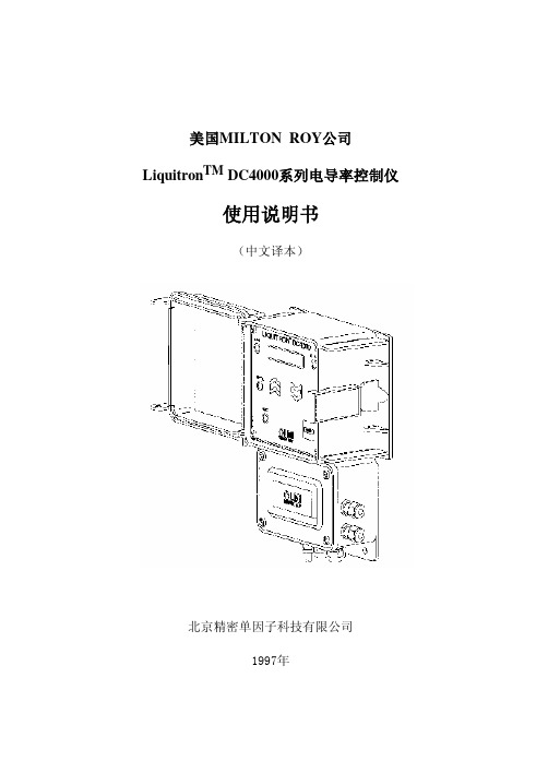
在启动时控制仪总是显示该项目,以及除去按键面板处于 使用状态的所有时间。
该主菜单项及其子程序可进行入下工作: ·观查电导率读数值。 ·改变(标定)电导率读数值。
(2)设定值:
该主菜单项及其子程序可进行入下工作: ·观查和改变电导率设定值。 ·观查和改变偏差值(回差值)。 ·观查和改变高限和低限电导率报警设定。
美国MILTON ROY公司 LiquitronTM DC4000系列电导率控制仪
使用说明书
(中文译本)
北京精密单因子科技有限公司 1997年
目录
1.0 DC4000型电导率控制仪介绍 前面板说明
2.0 安装 装配控制仪箱体 箱体安装尺寸 电气连接要求 端子板布置图
3.0 快速参考指南
4.0 主菜单 主菜单项目 菜单概述
DC4000型电导率控制仪是基于微处理器的电导率控制仪, 其设计可成用于各种需要精确控制总溶解固体和化学药剂投加 的水处理应用的形式。DC4000型电导率控制仪可以控制冷却 塔、锅炉和闭环系统的电导率和化学药剂投加就是许多应用中 的几种。
化学药剂投加可基于以下四个方面: ·具有锁定(限制)功能的投加和排放。 ·作为排放的百分比进行投加。 ·作为时间的百分比进行投加。 ·配有计数器的外部起动的装置。
因为流量计接线没有极性,所以输入可以颠倒。 输入到接线端子位置TB9-1。 输入到接线端子位置TB9-2。
流量开关输入: 该输入可用来连接一个提供开关闭路输出的流量开关或其
它设备。如果象这样的设备连接到DC-4000型控制仪,当该开 关处于“打开”位置时,其将起断开控制的作用。
8
该功能可用作一个安全过载,以避免给定条件下的控制作 用,如丧失流量。当使用流量开关(或其它设备)时,仅有继 电器电源被切断。仪器仍将显示现在的电导率,并可以充分使 用键盘。
Omega CN4000系列温度控制器用户指南说明书

e-mail:**************For latest product manuals: CN4000 SERIESTemperature ControllersShop online at User’s G ui d e***********************Servicing North America:U.S.A. Omega Engineering, Inc.Headquarters: Toll-Free: 1-800-826-6342 (USA & Canada only)Customer Service: 1-800-622-2378 (USA & Canada only)Engineering Service: 1-800-872-9436 (USA & Canada only)Tel: (203) 359-1660 Fax: (203) 359-7700e-mail:**************For Other Locations Visit /worldwideThe information contained in this document is believed to be correct, but OMEGA accepts no liability for any errors it contains, and reserves the right to alter specifications without notice.CONTENTSMODEL CONFIGURATION (2)SPECIFICATIONS (3)PARAMETER AND SETTING (4)SYMBOL DESCRIPTIONS (7)INSTRUMENT INSTALLATION AND WIRING (8)DISPLAY AND OPERATIONS (9)OPERATION DESCRIPTION (10)MODEL CONFIGURATIONModel DescriptionCN4116 (*)-(**)-(***) 1/16 DIN controllerCN4216 (*)-(**)-(***) 1/16 DIN controller, with 0.0 decimalCN414 (*)-(**)-(***) 1/4 DIN controllerCN424 (*)-(**)-(***) 1/4 DIN controller, with 0.0 decimalCN418V (*)-(**)-(***) 1/8 DIN Vertical controllerCN428V (*)-(**)-(***) 1/8 DIN Vertical controller, with 0.0 decimalCN418H (*)-(**)-(***) 1/8 DIN Horizontal controllerCN428H (*)-(**)-(***) 1/8 DIN Horizontal controller, with 0.0 decimal*Specify controlling output code from Output Options table below**Specify alarm code from Alarm Options table below***Low voltage power supply option (-LV)Controlling Output OptionsOption Type CodeRelay -R1DC SSR driver -DC1Alarming Output OptionsOption Type CodeRelay -R2DC SSR driver -DC2Low voltage power supply optionHz50/60AC/DC,-LV 24VSPECIFICATIONSThermocouple RTD Input TypeK S R E J N PT100Range ℃/ ℉0 to1300 ℃32 to 2372 ℉0 to1700℃32 to 3092 ℉0 to1600℃32 to 2412 ℉0 to1000℃32 to 1832 ℉0 to1200℃32 to 2192 ℉0 to 1300℃32 to 2372 ℉-200 to 800℃-328 to 1472 ℉Accuracy:CN 4116/CN414/CN4180.3%FS ± 1℃/1.8°FCN4216/CN424/CN428 0.3%FS ± 0.1℃/0.18°FTemperature Display ResolutionCN 4116/CN414/CN4181℃/1℉CN4216/CN424/CN4280.1℃/0.1℉ON / OFF ControlControl MethodAI PID Control with Auto Tuning (AT)Relay Output (1A/250VAC)Output TypeVoltage Output for SSR(12V/30mA)Limit High / LowAlarm(Modularization) High deviation/Low deviation100~240VAC (-15%, +10%), or 24VDC Supply Voltage50 to 60HzPower Consumption ≦ 3WOperating EnvironmentsTemperature: -10 to +60℃ / 14 to 140℉Humidity: 0~90RH%Electromagnetic compatibility (EMC) IEC61000-4-4: ± 4KV/5KHz IEC61000-4-5: 4KVPARAMETER AND SETTINGField parameter table (Primary parameters)Code Description Remarks SettingRange DefaultHIAL High limit alarm Alarm on when PV>HIALalarm off when PV<HIAL- AHYS-999~+3000 3000LoAL Low limit alarm Alarm on when PV<LoAL;alarm off when PV>LoAL + AHYS-999~+3000 -999HdAL Deviation highalarmAlarm on when PV-SV>HdAL;alarm off when PV-SV<HdAL - AHYS-999~+3000 3000LdAL Deviation lowalarmAlarm on when PV-SV<LdAL;alarm off when PV-SV>LdAL + AHYS-999~+3000 -999Loc Parameter LockLocAutoTuningSVPrimaryParameterSecondaryParameter0 X1 X X2 X X X3 X X X X808: allow to modify data or execute ATX : not allow to modify data or execute AT0~255 0System parameter table (Secondary parameters)Scb Input Shift Parameter Scb is used to make input shift tocompensate the error produced by sensor or inputsignal itself.PV-after-compensation=PV-before-compensation + Scb.-199~+400FILt PV input filter The value of FILt will determine the ability offiltering noise.When a large value is set, the measurement inputis stabilized but the response speed is slow.Generally, if great interference exists, then youcan increase parameter “FILt” gradually to makemomentary fluctuation of measured value lessthan 2 to 5.When the meter of the instrument is beingexamined at laboratory, “FILt” should be set to 0or 1 to short the response time.0~40 1Fru Selection of powerfrequency andtemperature scale50C: 50Hz, ℃50F: 50Hz, ℉60C: 60Hz, ℃60F: 60Hz, ℉50C, 50F,60C, 60F50CSPL Low limit of SV -999~3000SPH Upper limit of SV -999~3000400SYMBOL DESCRIPTIONS Symbol DescriptionorAL Input specification setting is incorrectOrInput wiring is disconnected/ thermocouple problem OrShort circuitedHIAL High limit alarm LoAL Low limit alarm HdAL Deviation high alarm LdAL Deviation low alarm EErr IC Software error 8888 IC Software errorINSTRUMENT INSTALLATION AND WIRINGWiring graph for instruments with dimension 1/4 DIN; 1/8 DIN Vertical and HorizontalNote: The compensation wires for different kinds of thermocouple are different, and should be directly connect to the terminals. Connecting the common wire between the compensation wire and the t e r m i n a l s w i l l c a u s e m e a s u r e m e n t e r r o r.Wiring graph for 1/16 DIN dimension instruments :DISPLAY AND OPERATIONS①Upper display window, displays PV,parameter code, etc.②Lower display window, displays SV,parameter value, or alarm③Setup key, for accessing parametertable and conforming parametermodification.④Data shift key, and auto tuning.⑤Data decrease key⑥Data increase key⑦LED indicator. MAN, PRG, MIO,COM, OP2, AL2, AU1 and AU2Com indicators is non-applicable.OP1 and AL1 will indicate I/O operation of the corresponding module.Basic display status:When power on, the upper display window of the instrument shows the process value (PV), and the lower window shows the set-point (SV). This status is called basic display status.When the input signal is out of the measurable range (for example, the thermocouple or RTD circuit is break, or input specification sets wrong), the upper display window will alternately display “orAL” and the high limit or the low limit of PV, and the instrument will automatically stop output. If the lower display window alternately display “HIAL”, “LoAL”, “HdAL” or “LdAL”, it means high limit alarm, low limit alarm, deviation high alarm, and deviation low alarm happening.OPERATION DESCRIPTIONz Set Value Setting:In basal display status, if the parameter lock “Loc” isn't locked, we can set setpoint (SV) by pressing 、 or . Press key to decrease the value, key to increase the value, and key to move to the digit expected to modify. Keep pressing or , the speed of decreasing or inscreasingvalue get quick. The range of setpoint is between the parameter SPL and SPH.The default range is 0~400.z Parameter Setting:In basal display status, press and hold for about 2 seconds can accessField Parameter Table. Pressing can go to the next parameter; pressing 、 or can modify a parameter. Press and hold can return tothe preceding parameter. Press (don't release) and then press key simultaneously can escape from the parameter table. The instrument will escape auomatically from the parameter table if no key is pressed within 30 seconds. Setting Loc=808 and then press can access System Parameter Table.●AI artificial intelligence control and auto tuningWhen AI artificial intelligence control method is chosen (CtrL=APId), the PID parameters can be obtained by running auto-tuning. In basal display status,press for 2 seconds, the “At” parameter will appear. Press to changethe value of At from “oFF” to “on”, then press to active the auto-tuning process. During auto tuning, the instrument executes on-off control. After 2-3 times of on-off action, the instrument will obtain the optimal control parametervalue. If you want to escape from auto tuning status, press and hold thekey for about 2 seconds until the "At" parameter appear again. Change “At”from “on” to “oFF”, press to confirm, then the auto tuning process will be cancelled.Note 1: If the setpoint is different, the parameters obtained from auto-tuning are possible different. So you’d better set setpoint to an often-used value ormiddle value first, and then start auto-tuning. For the ovens with goodheat preservation, the setpoint can be set at the highest applicabletemperature. Depending on the system, the auto-tuning time can befrom several seconds to several hours.Note 2: Parameter Ctl (on-off differential, control hysteresis) has influence on the accuracy of auto-tuning. Generally, the smaller the value of Ctl, thehigher the precision of auto tuning. But Ctl parameter value should belarge enough to prevent the instrument from error action around setpointdue to the oscillation of input. Ctl is recommended to be 2.0.Note 3: The instrument has the function of self-learning. It is able to learn the process while working. The control effect at the first run after auto tuningis probably not perfect, but excellent control result will be obtained after aperiod of time because of self-learning.10OMEGA’s policy is to make running changes, not model changes, whenever an improvement is possible. T his affords our customers the latest in technology and engineering.OMEGA is a trademark of OMEGA ENGINEERING, INC.© Copyright 2018 OMEGA ENGINEERING, INC. All rights reserved. T his document may not be copied, photocopied, reproduced, translated, or reduced to any electronic medium or machine-readable form, in whole or in part, without the prior written consent of OMEGA ENGINEERING, INC.FOR WARRANTY RETURNS, please have the following information available BEFORE contacting OMEGA:1. P urchase Order number under which the product was PURCHASED,2. M odel and serial number of the product under warranty, and3. Repair instructions and/or specific problems relative to the product.FOR NON-WARRANTY REPAIRS, consult OMEGA for current repair charges. Have the following information available BEFORE contacting OMEGA:1. Purchase Order number to cover the COST of the repair,2. Model and serial number of the product, and 3. Repair instructions and/or specific problems relative to the product.RETURN REQUESTS/INQUIRIESDirect all warranty and repair requests/inquiries to the OMEGA Customer Service Department. BEFORE RET URNING ANY PRODUCT (S) T O OMEGA, PURCHASER MUST OBT AIN AN AUT HORIZED RET URN (AR) NUMBER FROM OMEGA’S CUST OMER SERVICE DEPART MENT (IN ORDER T O AVOID PROCESSING DELAYS). The assigned AR number should then be marked on the outside of the return package and on any correspondence.T he purchaser is responsible for shipping charges, freight, insurance and proper packaging to preventbreakage in transit.WARRANTY/DISCLAIMEROMEGA ENGINEERING, INC. warrants this unit to be free of defects in materials and workmanship for a period of 25 months from date of purchase. OMEGA’s WARRANTY adds an additional one (1) month grace period to the normal two (2) year product warranty to cover handling and shipping time. This ensures that OMEGA’s customers receive maximum coverage on each product.If the unit malfunctions, it must be returned to the factory for evaluation. OMEGA’s Customer Service Department will issue an Authorized Return (AR) number immediately upon phone or written request. Upon examination by OMEGA, if the unit is found to be defective, it will be repaired or replaced at no charge. OMEGA’s WARRANT Y does not apply to defects resulting from any action of the purchaser, including but not limited to mishandling, improper interfacing, operation outside of design limits, improper repair, or unauthorized modification. T his WARRANT Y is VOID if the unit shows evidence of having been tampered with or shows evidence of having been damaged as a result of excessive corrosion; or current, heat, moisture or vibration; improper specification; misapplication; misuse or other operating conditions outside of OMEGA’s control. Components in which wear is not warranted, include but are not limited to contact points, fuses, and triacs.OMEGA is pleased to offer suggestions on the use of its various products. However, OMEGA neither assumes responsibility for any omissions or errors nor assumes liability for any damages that result from the use of its products in accordance with information provided by OMEGA, either verbal or written. OMEGA warrants only that the parts manufactured by the company will be as specified and free of defects. OMEGA MAKES NO OTHER WARRANTIES OR REPRESENTATIONS OF ANY KIND WHATSOEVER, EXPRESSED OR IMPLIED, EXCEPT THAT OF TITLE, AND ALL IMPLIED W ARRANTIES INCLUDING ANY W ARRANTY OF MERCHANTABILITY AND FITNESS FOR A PARTICULAR PURPOSE ARE HEREBY DISCLAIMED. LIMITATION OF LIABILITY: The remedies of purchaser set forth herein are exclusive, and the total liability of OMEGA with respect to this order, whether based on contract, warranty, negligence, indemnification, strict liability or otherwise, shall not exceed the purchase price of the component upon which liability is based. In no event shall OMEGA be liable for consequential, incidental or special damages.CONDITIONS: Equipment sold by OMEGA is not intended to be used, nor shall it be used: (1) as a “Basic Component” under 10 CFR 21 (NRC), used in or with any nuclear installation or activity; or (2) in medical applications or used on humans. Should any Product(s) be used in or with any nuclear installation or activity, medical application, used on humans, or misused in any way, OMEGA assumes no responsibility as set forth in our basic WARRANT Y /DISCLAIMER language, and, additionally, purchaser will indemnify OMEGA and hold OMEGA harmless from any liability or damage whatsoever arising out of the use of theProduct(s) in such a manner.Where Do I Find Everything I Need forProcess Measurement and Control?OMEGA…Of Course!Shop online at TEMPERATUREM U Thermocouple, RTD & Thermistor Probes, Connectors,Panels & AssembliesM U Wire: Thermocouple, RTD & ThermistorM U Calibrators & Ice Point ReferencesM U Recorders, Controllers & Process MonitorsM U Infrared PyrometersPRESSURE, STRAIN AND FORCEM U Transducers & Strain GagesM U Load Cells & Pressure GagesM U Displacement TransducersM U Instrumentation & AccessoriesFLOW/LEVELM U Rotameters, Gas Mass Flowmeters & Flow ComputersM U Air Velocity IndicatorsM U Turbine/Paddlewheel SystemsM U Totalizers & Batch ControllerspH/CONDUCTIVITYM U pH Electrodes, Testers & AccessoriesM U Benchtop/Laboratory MetersM U Controllers, Calibrators, Simulators & PumpsM U Industrial pH & Conductivity EquipmentDATA ACQUISITIONM U Communications-Based Acquisition SystemsM U Data Logging SystemsM U Wireless Sensors, Transmitters, & ReceiversM U Signal ConditionersM U Data Acquisition SoftwareHEATERSM U Heating CableM U Cartridge & Strip HeatersM U Immersion & Band HeatersM U Flexible HeatersM U Laboratory HeatersENVIRONMENTALMONITORING AND CONTROLM U Metering & Control InstrumentationM U RefractometersM U Pumps & TubingM U Air, Soil & Water MonitorsM U Industrial Water & Wastewater TreatmentM U pH, Conductivity & Dissolved Oxygen InstrumentsM4545/0418。
MTS-4000OTDR操作指南
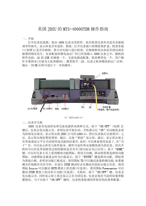
美国JDSU的MTS-4000OTDR操作指南一、开始打开仪表包装箱,取出4000仪表及其附件,依次检查仪表外壳是否有破损或零件缺失,显示屏是否有划伤、裂痕,打开仪表接口的塑胶保护盖,检查各接口(如图1)是否有破损,重点对光接口进行检查,仔细观察其内部是否清洁或有破裂的情况发生。
仪表配备的锂电池出厂时已经装载入4000仪表之中,随机的附件包括:1G的USB存储器一个、交流电源适配器、软质携带包一个、用户操作手册两本(分别为主机和模块)、携带把手一副、仪表主机和模块的出厂证明。
确认一切OK后即可进行下一步的操作。
二、仪表开关机4000仪表有电池供电和交流电源供电两种方式,按下“ON/OFF”(如图2)键后,仪表会发出提示音,表明仪表开始启动,开机指示灯“ON”从闪烁状态变为持续发出绿光,显示屏出现JDSU公司的LOGO后,然后仪表执行自检程序,之后,显示屏出现短暂的黑屏,随后,出现“帮助”显示屏,最后,显示屏出现主页界面或显示平台关闭前所选功能的结果页。
此时,可以准备使用设备了。
在“关于”页,可以显示所有与软件版本、硬件可选件和安装模块相关的信息、初次开机时可以在此界面检查定制的模块是否齐全(绿勾标出为已启用),按下“HOME”键,可以在仪表主页上看到模块功能图标,使用方向键,移动到需要选择的功能图标,功能图标未被选定时为白底显示,按下“ENTER”键选择该功能,图标变为黄底白框,表明该功能已被选定。
使用图标TD可以激活流量检测功能,如果被测光纤线路有光信号时,在进行OTDR测试时会在测试页面给出提示信息。
使用图标Source可以激活ODTR模块上的光源(可选项),使用图标Powermeter可以激活OTDR模块上的功率计功能(可选项)。
关机时,按下“ON/OFF”键,仪表会发出提示音,同时显示屏上将会显示正在关闭仪表,仪表会保存当前的结果和配置情况。
当下次按下“ON/OFF”键时,仪表将重新调用所保存的结果和配置。
DCK电导系列说明

DCK-4230/4231/4232/4332电导率仪使用说明一、使用前注意事项:1、安装、使用前请详细阅读本说明书相关章节,防止错误操作,造成测量误差或仪表损坏。
2、不恰当的安装和不合适的流速会使测量出现很大偏差,请详细了解安装章节。
3、此仪表属于精密电化学仪表,应由了解和掌握该专业知识的人员负责安装、操作。
二、保修条款:1、自购买之日起,产品质量保证期为一年。
在质量保证期内,产品出现质量问题,公司负责免费维修或更换产品。
2、公司对售出产品提供终身维护服务。
3、对下列原因造成产品的损坏,不在保修范围之内:A、使用、维护不当造成的烧毁、浸水;B、未经许可进行的改装和误用;C、超出本公司产品规定的使用环境造成的损坏;D、因选型不当造成的附带损失;E、安装、使用不当造成的线缆断裂、损坏;F、私自拆线或接线造成传感器测量不准;G、不谨慎拆卸造成的接头内部断线。
一、产品概述:DCK-4000系列工业在线电导率仪是工业流程水质连续测量与控制的分析仪表,采用一个内藏的微型计算机芯片存储、计算、补偿和有关测定电导率值的所有计算参数,例如:溶液电导率的常数修正,温度补偿,参数之间的相互换算,各项信号输出和控制的设定。
丰富的软件功能,使的本系列仪表具有功能完善、操作方便,抗干扰性强,测量准确,运行稳定,工作可靠,标准化程度高和极少维护等特点。
广泛应用于反渗透、电渗析,海水淡化,化学制程,中水回用及各种水处理装置作水质连续监控;水冷却系统、中央空调、锅炉底水的电导率监视控制和药剂投加。
特点:1.新一代翠绿色、大型字段式背景光液晶屏,具有多种提示符号及状态显示支持μS/cm,ppm (TDS),mS/cm,TEMP(温度)多功能选择显示;2.支持多种电极常数和电极离散性校正(0.1 cm-1 ;1.0cm-1;10cm-1);3.指定量程/自动量程双选择设定,可选的上限/下限动作模式,双路继电器构成三位控制;4.仪表/变送器双模式传送,隔离型、可迁移4~20mA电流环,适配所有国别、型号的PLC模块(DCK-4332型号),具有强大的兼容性。
400DS说明书
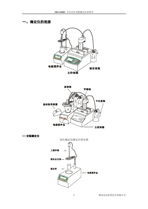
一、滴定仪的连接1.1安装滴定台电位滴定仪滴定台的安装水分测定仪滴定台的安装1.2滴定管1.3仪器背观图:主控制箱①电源开关②12V输出口2③12V输出口1 ④打印线接口:与打印机数据线连接⑤数据下载接口:与计算机连接⑥双铂电极接口⑦复合电极接口⑧指示电极接口⑨参比电极接口电磁搅拌台①COOLER:外接致冷器接口②REMOTE:外接控制接口③上搅拌接口④数字温度传感器接口⑤12V电源接口⑥加热器电源输出⑦加热器电源输入自动给排液器①溶剂接口②12V电源输入接口③12 V电源输出接口④废液接口1.4连接电极选用适当电极,将电极接头插入数据处理器后的相应电极接口,并锁紧,将电极固定于滴定台上。
双铂电极复合电极指示电极参比电极根据上述介绍将滴定仪安装好后,即可开始进行滴定。
在实验开始前要熟悉滴定仪的操作过程及各功能键的使用。
二、键盘说明2.1功能键系统:进行系统参数设定、实验员登录、修改密码等操作。
样品:调用预先设定好的方法,输入样品信息,开始滴定。
方法:选择/编辑方法,方法中包含公式编辑;在需要输入中文时按此键可以切换至区位码输入。
清洗:定量更换滴定管路中的液体,可以设定一个固定的值来定量推出一定量的滴定液;在浏览标定结果时按此键可以删除所有标定值。
单步:设定定量推出滴定管的液体,在最大体积足够大时连续按住单步可以达到清洗的效果。
公式:浏览、编辑公式,重新计算实验结果。
数据:浏览、统计、打印保存的数据;在公式编辑中,数据键可以用来输入负号。
校正:启动pH测量及校正功能。
可以显示pH值,校正电极斜率,显示电极斜率及删除原来校正的电极斜率。
回零:驱动主控制箱转动使滴定管活塞回到初始位置,此时滴定管处于可拆卸状态;在浏览标定结果时按此键可以删除当前标定值。
启动:启动一个过程,如启动滴定过程、启动数据打印过程等。
2.2数字键0~9:数字输入,选项选择。
“.”:输入小数点。
2.3辅助功能键退格:在输入状态下逐个删除原有的内容。
MTS4000光时域反射仪使用

2011-8-11
工作原理
- OTDR将一束光脉冲打进光纤回路,回路中的各种事件 OTDR将一束光脉冲打进光纤回路 将一束光脉冲打进光纤回路,
对于光脉冲会有不同程度的反射量, 对于光脉冲会有不同程度的反射量,这些反射光再沿 着光纤回到发射端,处理器将过程中收集的所有资料, 着光纤回到发射端,处理器将过程中收集的所有资料, 描绘出一条时间与反射能量的曲线
2011-8-11
2011-8-11
适用范围
接头损耗 光纤率减 线路测试 在线监控 故障点分析 光纤总长度
2011-8-11
注意事项
1.在尚未接好光纤的情况下,请勿执行扫描. 1.在尚未接好光纤的情况下,请勿执行扫描. 在尚未接好光纤的情况下 2.光纤插头端面的清洁非常重要,过高的突起形表 2.光纤插头端面的清洁非常重要, 光纤插头端面的清洁非常重要 示插入损失与回返损失变大. 示插入损失与回返损失变大. 3.可能因锁入光纤转接器的方法不当 可能因锁入光纤转接器的方法不当, 3.可能因锁入光纤转接器的方法不当,导致转接器 内的陶瓷套筒破裂,这将使得扫描结果时好时坏. 内的陶瓷套筒破裂,这将使得扫描结果时好时坏. 4.电池为易耗品 一般寿命为2 电池为易耗品, 4.电池为易耗品,一般寿命为2年。
2011-8-11
功能键介绍(2)
FILE(文件) (文件) 此按钮调用文件与目录管理菜单。它能够: 此按钮调用文件与目录管理菜单。它能够: – 选择存贮媒介:内部存贮器、USB存贮卡;文件名与格式,与存 选择存贮媒介:内部存贮器、 存贮卡; 存贮卡 文件名与格式, 贮在文件内的数据相关的信息。 贮在文件内的数据相关的信息。 – 存贮文件或调用它们进行选择、复制或删除将它们在目录与子目 存贮文件或调用它们进行选择、 录内进行分类。 录内进行分类。 SETUP(设置) (设置) 此按钮用于测试配置菜单。菜单内容取决于所使用的功能。 此按钮用于测试配置菜单。菜单内容取决于所使用的功能。 RESULTS(结果) (结果) 此按钮调用结果页(例如, 模块:反射计迹线、 此按钮调用结果页(例如,对于 OTDR 模块:反射计迹线、结果 与结果列表)并被用于分析结果。 与结果列表)并被用于分析结果。 START/STOP(启动/停止) (启动/停止) 启动与停止测试
分析电导率仪的按键说明和使用方法 电导率仪如何做好保养
分析电导率仪的按键说明和使用方法电导率仪如何做好保养为了让大家能够正确的使用电导率仪,我特意为您整理了认真的电导率使用方法。
首先在使用电导率仪前,我们应了解设备各个按键的作用,以便下一步更好的使用,以下为了让大家能够正确的使用电导率仪,我特意为您整理了认真的电导率使用方法。
首先在使用电导率仪前,我们应了解设备各个按键的作用,以便下一步更好的使用,以下是电导率仪的紧要按键及功能说明:1、电极常数:按此键快速设置和查看电极常数2、温补系数:按此键设置和查看温补系数3、确定:按此键接受设置4、测量:按此键回到测量状5、滚动(▼,▲):可用来更改测量方式中的人工温度设置和更改电极常数和温补系数再了解电导率仪的使用方法:1、未开电源开关前,察看表针是否指零,如不知零,可调整表头上的螺丝使表针指零。
2、将校正、测量开关扳在“校正”位置。
3、插接电源线,打开电源开关,并预热数分钟(待指针完全稳定下来为止)调整“调正”器使电表满度指示。
4、当使用(1)~(8)量程来测量电导率低于300 的液体时,选用“低周“,这时将板向“低周“即可。
当使用(9)~(12)量程来测量电导率在300 至范围里的液体时,则将扳向”高周“。
5、将量程选择开关扳到所需要的测量范围,如预先不知被测溶液电导率的大小,应先把其扳在最大电导率测量档,然后逐档下降,以防表针打弯。
6、量读数:一般的测量其“常数”的旋钮都打到1.0档,测量前调正(ADI)旋到最大值,然后再渐渐地调整,把测量开关打到校正档调好零点,选好量程,再把测量开关打到测量的位置然后再读数。
7、电极的使用:使用时用电极夹夹紧电极的胶木帽,并通过电极夹把电极固定在电极杆上。
以上就是全部内容,假如还想了解更多关于电导率仪的资讯可以关注我们~—专业分析仪器服务平台,试验室仪器设备交易网,仪器行业专业网络宣扬媒体。
相关热词:等离子清洗机,反应釜,旋转蒸发仪,高精度温湿度计,露点仪,高效液相色谱仪价格,霉菌试验箱,跌落试验台,离子色谱仪价格,噪声计,高压灭菌器,集菌仪,接地电阻测试仪型号,柱温箱,旋涡混合仪,电热套,场强仪万能材料试验机价格,洗瓶机,匀浆机,耐候试验箱,熔融指数仪,透射电子显微镜。
电导率仪使用说明书
一、 原理电导率是以数字表示溶液传导电流的能力。
水的电导率与其所含无机酸、碱盐的量有一定的关系,当它们的浓度较低时,电导率随着浓度的增大而增加,因此,该指标常用于推测水中离子的总浓度或含盐量。
电导(G )是电阻(R )的倒数。
因此当两个电极(通常为铂电极或铂黑电极)插入溶液中,可以测出两电极间的电阻R 。
根据欧姆定律,温度一定时,这个电阻值与电极间距L (cm )正比,与电极的截面积A (cm 2)反比,即R =ρ×AL其中ρ为电阻率,是长1cm ,截面积为1cm 2导体的电阻,其大小决定于物质的本性。
据上式,导体的电导(G )可表示成下式:G =R 1=ρ1×L A =K ×J1其中,K=1/ρ称为电导率,J =L /A 称为电极常数电解质溶液电导率指相距1cm 的两平行电极间充以1cm 3溶液时所具有的电导。
由上式可见,当已知电极常数(J ),并测出溶液电阻(R )或电导(G )时,即可求出电导率。
二、 CON-2A 电导率仪的特点CON-2A 型电导率仪是实验室测量水溶液电导率必备的仪器,它广泛应用于石油化工生物医药污水处理环境监测矿业冶炼以及大专院校和科研单位等。
仪器的特点如下:1. 仪器具有电极常数及温度补偿功能。
2. 仪器采用高性能集成电路组成的性能稳定的正弦波发生器,因此读数稳定,漂移小。
3. 仪器采用了相敏检波器,抑制了由电极引线分布电容对测量的影响,因而本仪器无需电容补偿,并且使低电导率测量精度大大提高。
三、 仪器的结构1. 电极常数调节旋钮:对不同电极进行常数调节。
2.温度旋钮:对被测溶液进行温度补偿。
3.量程开关旋钮:校准/量程选择开关,分校准、2 0µs、200 µs、2000 µs和20ms四个档4.校准调节旋钮:校准量程满度。
图一前面板示意图5.后面板结构图二后面板示意图①电极插座②接地端子③电源插座④电源开关四、技术性能1.测量范围:仪器测量范围为0~2×10⁵(µs/cm),共分四个量程。
美国米顿罗(MILTON ROY)公司DP5000智能化系统监控仪使用说明书

TB4 插头1~2:光隔离输入—如果没有流量开关,可加接跳线。 TB4 插头3~4:光隔离输入—如果没有液位开关,可加接跳线。 TB4 插头5~6:串行通讯线(选用附件)。 TB4 插头7~8:温度输入(铂1000W探头)。 TB4 插头9~10:用于预放大器的电源。
3.2.2 外部电缆说明 一般配有美国制式的长度为2米的交流电电缆,以及两个 30cm长度AC插座(开/关方式)或两个3米长度的计量泵驱动电 缆(比例方式)。PH探头上安装有一个BNC插座。 正确连接两个计量泵,安装PH探头,将电缆铺设到控制仪 处并接到BNC插座上。如果探头和控制仪的距离超过8米,选用 用预放大器以减小噪音的影响。如果存在这种情况,使用预放 大器所需的+5V/-5V接线端子。电流强度必须小于10mA。
TB3 插头1~2:光隔离输入—低点关闭计量泵(显示为OFF)。 TB3 插头3~4:光隔离输出—当报警条件发生时为低点。 TB3 插头5~6:光隔离输出—脉冲链驱动计量泵A。 TB3 插头7~8:光隔离输出—脉冲链驱动计量泵B。 TB3 插头9~10:空闲,未编程。 TB3 插头11~12:与PH值成比例的4~20mA输出(范围可编程)
开关所对应的接线端子,还可连接毫安或通讯端子(当配有选
用件时)。用于电极预放大的±5V电源也设在接线端子上。对 于4~20mA的选用件,可提供最大500Ω的电阻值。请参照图4 和图5。
用于比例控制的电缆 用于开关控制的电缆
3米
305mm
电源电缆 1.8 米
接配 pH 电极 ( BNC 接头)
备选件接线口
:这些按键用于关闭显示屏上的数值。
+
:同时按下这两个按键将锁定按键面板,
以避免偶然的更改。第二次按下这两个
Omega CN-TOT-A Series 蜂窝式热敏电导温度控制器说明书

Immediate hazards which WILL result in severe personal injury or death
Hazards or unsafe practices which COULD result in severe personal injury or death
Hazards or unsafe practices which COULD result in minor personal injury or property damage.
SAVE THESE INSTRUCTIONS!
Additional copies of this manual are available upon request.
End User Must Comply to the Following:
• Must be mounted vertically for outdoor use • Only qualified personnel are allowed to connect
electrical wiring. • All electrical wiring must follow local electrical
codes and highly recommend following NEC Article 427. • Final installation / wiring is to be inspected by the authority who has jurisdication in the area that the heater and temperature controller is installed. • The end-user is responsible for providing a suitable disconnecting device. • The end-user is responsible for providing suitable electrical protection device. It is highly recommended that a ground fault circuit breaker is used. Failure to observe these warnings may result in personal injury or damage to the controller.
DELTA4000系列12kV电子诊断系统说明书

DELTA4000 Series12 kV Insulation Diagnostic SystemnEasy to use with automatic and manual operationnAccurate and repeatable measurement results with high noise suppression for the most extreme conditionsnLightweight, rugged two-piece design, with unit weights of 14 kg and 22 kgnNew built-in intelligent temperature correction eliminates the need fortemperature correction tables (patent pending)nNew automatic voltage dependence detection (patent pending)DESCRIPTIONThe new DELTA4000 Series is a fully automatic 12 kV insulation power factor/dissipation factor (tan ∂) test set designed for condition assessment of electrical insulation in high voltage apparatus such as transformers, bushings, circuit breakers, cables, lightning arresters and rotating machinery. In addition to performing insulation power factor tests, the DELTA4000 Series can be used to measure the excitation current of transformer windings as well as to performautomatic tip-up tests and HV turns-ratio testing (an optional TTR Capacitor is available).The test set is designed to provide a comprehensive ACinsulation diagnostic test. The high power variable frequency design generates its own test signal independent of line frequency quality and the hardware design uses the latesttechnology available for digital filtering of the response signal. As a result, the DELTA4000 Series produces reliable results and stable readings in the shortest time with the highest accuracy, even in high interference substations.The DELTA4000 Series operates with PowerDB software for automatic testing and reporting or with Delta Control software for real-time manual testing.Measurements include voltage, current, power (loss), tan delta, power factor and capacitance. The test results are automatically stored in the computer and can also be downloaded directly to USB storage or a printer.DELTA4110 test set is to be used with an external computer (not included) while the DELTA4310 test set comes with an onboard computer.APPLICATIONSTEST CAPABILITIESnPower transformersn Distribution transformers n Instrument transformers n Rotating machines n Oil insulationn Bushings n Cables n Capacitors n Circuit breakers nSurge arrestorsnPower factorn Dissipation factor (tan ∂)n Excitation current n Automatic tip-up n Watts loss nInductancen Capacitance n Voltage n Current nTurns ratio** with optional accessoryDELTA4110 test setto be used with external computerDELTA4310 test set with onboard computerDELTA4000 Series12 kV Insulation Diagnostic System1981DELTA4000 Series 12 kV Insulation Diagnostic SystemFEATURES AND BENEFITSIndustry-Leading Performance and Accuracyn Generates its own test signal – resulting in accurate and clean measurements even in the most severe conditions and in the event power is required from a portable generator.n High noise suppression and advanced signal acquisition circuitry can handle up to 15 mA interference current ora signal to noise ratio of up to 1:20 resulting in extremely accurate and clean measurements even in the most severe conditions.n Industry leading frequency range (1-500Hz) reveals details in the insulation characteristics that are not possible to detect with other test sets.n Intelligent temperature correction (patent pending) allows the user to estimate the actual temperature dependence of the test object by measuring tan delta overa frequency range. Mathematically calculating accurate individual temperature correction results in a more accurate measurement of the insulating material’s condition.n Automatic voltage dependence detection (patent pending) Various high voltage components may have a voltage dependence where tip-up testing is recommended (i.e. the dissipation factor is pending test voltage). The DELTA4000 Series has a patented method for detecting voltage dependence and gives the user an alarm, suggesting additional tests should be performed at different voltage levels.n Fast test time - Dynamic noise suppression minimizes actual test time.Industry’s Lightest and Most Ruggedn Industry’s lightest two-piece design, weighing14 kg + 22 kg saves on effort, space, and shipping costs.n Designed for various work environments: in the field; in a test van; in a manufacturing facility; or in a repair facility.n Units have performed successful testing in the world’s most extreme conditions including: high temperatures,low temperatures, high elevations, high noise, and high humidity.Software Package — PowerDB Advancedn Automatic and manual operation – provides fully automatic operation for tan delta as well as excitation current and tip-up testing. The user simply selects the test object and the unit will automatically run the complete test and report the results back to the test form. The DELTA4000 Series can also be used with Delta Control software in a manual testing mode, where the operator has full control to set the test parameters including the possibility to manually adjust the output voltage and measure output current and otuput voltage continuously.n Easy to save and retrieve data – information will be saved in an XML file with all historical data. This allows the user to view previous year’s test sheet or trend specific test points. n Simple, intuitive, easy-to-use interface between operator and instrument.n Suspect data points are flagged visually with a red highlight.n Capability to trend a specific asset over time.n Easily recall transformer setups from the settings menu.n Ability to interface with other transformer test units such as MLR10 (leakage reactance, capacitance banks),TTR-series (transformer turns ratio), MTO210 (winding resistance), MIT/S1-series (DC insulation), MCT-series (CT measurements).Optional Database Software - PowerDB ProA comprehensive Acceptance and Maintenance TestData Management Software and database that allows you synchronize information from all of your different types of instruments into a single database, trend test results to similar equipment and the ability to design or modify test forms.n Easily import your historical data points even from other manufacturers’ databases.n Analysis and trending - As an immediate on-site assessment the user can compare the latest measurements with stored data and see how the insulation valuesmay have changed over time (trending). Comparison of measurements captured at different voltages and different frequencies can also be observed. Pass/Fail criteria canbe set to immediately identify a possible problem in your insulation.PREMIUM SUPPORTRegion dependent; please contact your nearest Megger Sales Representative for details. Available in 1-yr, 3-yr, and 5-yr agreements.n Extended product warranty protects your unit beyond the standard manufacturer’s warranty.n Loaner units and loaner accessories provide guaranteed reliability. Loaners are delivered within 1-2 business days.n Field application support provided by former utility engineers and PhD’s who have vast substation and transformer experience to guide you through your testing procedures and answer your questions.n Software support and guidance through installation, importing older data, customizing forms, comparing results, and data trending.n Annual onsite training on the equipment software, theory, field testing, data analysis, and PowerDB. Training can be provided on-site or at any of the Megger facilities.DELTA4000 Series 12 kV Insulation Diagnostic SystemSPECIFICATIONSInput Power90 - 264 V45 - 66 Hz16 A maxNo loss in performance when used with portable generator. Also possible to use 12 V dc with optional inverter kit (P/N 35271-16) Output Voltage0 to 12 kV, continuously adjustableTest Frequency Range45-70 Hz (12 kV)15-400 Hz (4 kV)1-505 Hz (250V)0.0001 Hz maximum resolutionOutput Power3.6 kVAOutput Current300 mA (4 minutes)200 mA (30 minutes)100 mA (continuous)The power supply capacity can be expanded to 4 A at 12 kV using the optional Resonating Inductor, (Cat. No. 670600-1). Measuring RangesVoltage25 V to 12 kV, 1 V resolutionCurrent0 to 5 Amps, 0.1 μA maximum resolution. The measurement can be corrected to either 2.5 kV or 10 kV equivalents.Capacitance0 to 100 μF, 0.01 pF maximum resolutionInductance6 H to 10 MH, 0.1 mH maximum resolutionPower factor0-100% (0-1), 0.001% maximum resolutionDissipation factor0-100 (0-10,000%), 0.001% maximum resolutionWatt Loss0 to 2 kW, actual power, 0 to 100 kW when corrected to 10 kV equivalent. 0.1 mW maximum resolution. The measurement can be corrected to either 2.5 kV or 10 kV equivalents.Temperature CorrectionIntelligent temperature correctionfrom 5°C to 50°C insulation test temperature to 20°C reference Standard tablesAs by international standards and manufacturers’ dataAccuracyVoltage ±(1% of reading + 1 digit)Current ±(1% of reading + 1 digit)Capacitance ±(0.5% of reading + 1 pF)Inductance ±(0.5% of reading + 1 mH)Power Factor ±(0.5% of reading + 0.02%)Dissipation Factor ±(0.5% of reading + 0.02%)Watt Loss ±(1% of reading + 1mW)Frequency ±0.005% of readingMeasurementThe following test modes are available:UST: Ungrounded Specimen TestingUST-R: UST: Measure Red, Ground BlueUST-B: UST: Measure Blue, Ground RedUST-RB: UST: Measure Red and Blue GST: Grounded Specimen TestingGST-GND: GST: Ground Red and BlueGSTg-R: GST: Guard Red, Ground BlueGSTg-B: GST: Guard Blue, Ground RedGSTg-RB GST: Guard Red and BlueNoise ImmunityElectrostatic15mA induced noise into any test lead with no loss of measurement accuracy at maximum interference to specimen current of 20:1Electromagnetic500 μT, at 50/60 Hz in any directionComputer InterfaceEthernet and USBPC RequirementsDELTA4110Operating system: Windows XP/Vista/7Processor: Min Pentium 1 GHzMemory: Min 1024 Mb RAMHard drive: Min 1 Gb availableInterface: USB and EthernetDELTA4310Internal PC with 8.4’’ full-color VGA, full QWERTY keypad, navigational pushbuttons, and joystick (external mouse can be connected), on-screen view of test forms, USB printer interface.Communication/Control/Data Management Software PowerDB and DELTA ControlEnvironmentTemperatureOperating: -20 to +55° C (-4 to +131° F)Storage: -50 to +70° C (-58 to +158° F)Relative humidityOperating: 0 to 95% non-condensingStorage: 0 to 95% non-condensingStandardsSafetyIEC/EN 61010-1:2001Shock and vibrationIEC 68-2-31, first edition, drop and topple (push over)IEC 68-2-31, second edition, free fallISTA 2AEMCFCC 47 CFR Part 15 Class A Emissions requirements (USA) (FCC Subpart B of Part 15 Class A)EN 55011:1998/A1:1999/A2:2002 Group 1 Class A ISM Emissions requirements (EUROPE)AS/NZS CISPR 11:2004 Class A ISM Emissions requirements (Australia)EN 61326:1997/A1:1998/A2:2001/A3:2003IEC/EN 61000-4-2/3/4/5/6/8/11IEC/EN 61000-6-2Test Equipment Specifications Met: IEC/EN 61000-6-4;IEC 801-2(1984) Electrostatic Discharge; ANSI/IEEE C37.90.1 Surge Withstand CapabilityDimensionsControl Unit: 290 x 290 x 460 mm (11 x 11 x 18 in.)High Voltage Unit: 290 x 290 x 460 mm (11 x 11 x 18 in.)*Does not include handles.WeightDELTA4100 DELTA4300 DELTA4010 Cables14 kg (31 lbs) 15 kg (33 lbs) 23kg (48 lbs) 15 kg (33 lbs)DELTA4000 Series12 kV Insulation Diagnostic SystemISO STATEMENTRegistered to ISO 9001:2000 Cert. no. 10006.01DELTA4000_DS_US_Megger is a registered trademark All information contained herein is subject to change without noticeUKArchcliffe Road, Dover CT17 9EN EnglandT +44 (0) 1 304 502101 F +44 (0) 1 304 207342******************UNITED STATES 4271 Bronze WayDallas, TX 75237-1019 USA T 1 800 723 2861 (USA only) T +1 214 333 3201 F +1 214 331 7399******************OTHER TECHNICAL SALES OFFICESValley Forge USA, College Station USA, Täby SWEDEN, Sydney AUSTRALIA, Ontario CANADA, Trappes FRANCE, Oberursel GERMANY, Mumbai INDIA, Johannesburg SOUTH AFRICA, Aargau SWITZERLAND, Chonburi THAILAND, and Dubai UAE。
Omega CDCN系列电导仪产品说明书
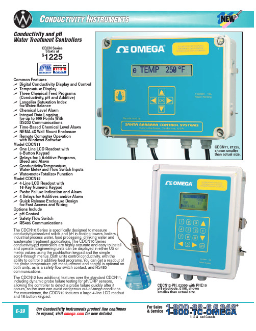
CDSA-1413
23
1413 µmho/cm conductivity solution, 946 mL (1 qt)
CDSA-1500
10
1500 µmho/cm conductivity solution, 946 mL (1 qt)
Comes complete with operator’s manual and 3V lithium battery. Probes sold separately.
RS232, RS485 RS232, RS485
RS232 RS232 RS232, RS485 RS232, RS485
Keypad/Display 5-button/one line 5-button/one line 5-button/one line 5-button/one line 16-button/four line 16-button/four line 16-button/four line 16-button/four line
PHA-7
5
7.00 pH buffer solution, 500 mL (1 pt) bottle
PHA-10
5
10.00 pH buffer solution, 500 mL (1 pt) bottle
CDSA-45
10
45 µmho/cm conductivity solution, 946 mL (1 qt)
ߜ Three Chemical Feed Programs (Conductivity, pH and Additive)
ߜ Langelier Saturation Index for Water Balance
电导率 仪器的基本操作
第1章功能特点1.1 基本功能1、高智能化:智能在线电导率仪采用高精度AD转换和单片机微处理技术,能完成电导率测量、温度测量、温度自动补偿、量程自动转换、仪表自检等多种功能。
2、高可靠性:元器件集成到一块线路板上, 没有了复杂的功能开关和调节旋钮。
3、抗干扰能力强:电流输出采用光电耦合隔离技术,抗干扰能力强,实现远传。
具有良好的电磁兼容性。
4、防水防尘设计:防护等级IP65,适宜户外使用。
5、自动量程转换:在电极所覆盖的测量范围内实现量程自动转换。
6、RS485通讯接口:可方便联入计算机进行监测和通讯(选配)。
8、相敏检波:消除导线对电导率测量的影响。
1.2 方便的中文菜单式操作1、中文显示、中文菜单:采用菜单结构,类似微机操作,操作简单,操作步骤全程中文导引,可不用说明书,即可方便完成。
2、多参数同屏显示:在同一屏幕上显示电导率、输出电流、温度和状态等。
3、优良的显示方式选用带背光的192× 64点阵图形式液晶显示屏,实现了图形和中文的显示。
可调的均匀背景光,在户外昏暗条件下也能清晰观察操作。
4、仪表稳定不死机看门狗程序确保仪表连续工作不会死机。
5、输出电流设置与检查功能手动电流源功能,可检查和任意设定输出电流值,方便检测记录仪和下位机。
7、软件设定电流输出方式4~20mA输出对应的电导率值可以任意设定。
1.4 优良的网络功能(选配定制)系列仪表保留了传统的隔离电流输出功能。
具有RS485通讯接口,可使仪表方便地联入计算机进行监测和通讯。
第2章技术指标1、电导率测量范围:0.01~30μS/cm (配0.01电极);0.1~300μS/cm (配0.1电极);1.0~3000μS/cm(配1.0 电极);10~30000μS/cm(配10.0电极);2、电子单元基本误差:电导率:±0.5%FS,温度:±0.2℃;3、自动温度补偿范围: 0~80.0℃,25℃为基准温度;4、被测水样:0~80.0℃,1.6MPa;5、仪器基本误差:电导率:±1.0%FS,温度:±0.5℃;6、电子单元自动温度补偿误差:±0.5%FS;7、电子单元重复性误差:± 0.2%FS±1个字;8、电子单元稳定性:±0.2%FS±1个字/24h;9、电流隔离输出:4~20 mA(负载<750Ω);10、输出电流误差:≤±1%FS;11、电子单元环境温度影响误差: ≤±0.5%FS;12、电子单元电源电压影响误差: ≤±0.3%FS;13、报警继电器:AC220V,3A;14、通讯接口;RS485(选配)15、电源:AC220V±22V ,50Hz±1Hz;16、防护等级:IP65;17、数据连续掉电保存时间:10年18、外形尺寸:96(长)×96(宽)×120(深)mm;开孔尺寸:92~92 mm19、重量: 1.0kg ;20、工作条件:环境温度0~60℃相对湿度<85%;21、可配电极:0.01、0.1、1.0、10.0四种电导电极。
RD4000中文手册

罗德与施瓦茨 DELTA4000系列 12 kV 绝缘故障诊断仪 用户手册说明书
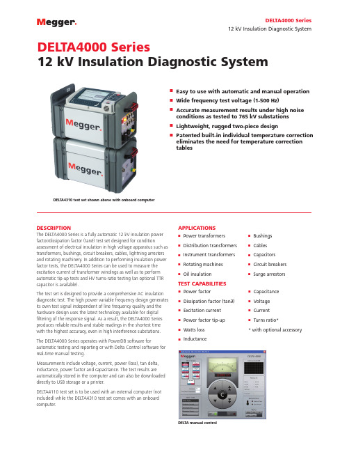
DELTA4000 Series12 kV Insulation Diagnostic Systemn Easy to use with automatic and manual operation n Wide frequency test voltage (1-500 Hz)n Accurate measurement results under high noise conditions as tested to 765 kV substations n Lightweight, rugged two-piece designnPatented built-in individual temperature correction eliminates the need for temperature correction tablesDESCRIPTIONThe DELTA4000 Series is a fully automatic 12 kV insulation power factor/dissipation factor (tan∂) test set designed for conditionassessment of electrical insulation in high voltage apparatus such as transformers, bushings, circuit breakers, cables, lightning arresters and rotating machinery. In addition to performing insulation power factor tests, the DELTA4000 Series can be used to measure the excitation current of transformer windings as well as to perform automatic tip-up tests and HV turns-ratio testing (an optional TTR capacitor is available).The test set is designed to provide a comprehensive AC insulation diagnostic test. The high power variable frequency design generates its own test signal independent of line frequency quality and the hardware design uses the latest technology available for digital filtering of the response signal. As a result, the DELTA4000 Series produces reliable results and stable readings in the shortest time with the highest accuracy, even in high interference substations.The DELTA4000 Series operates with PowerDB software forautomatic testing and reporting or with Delta Control software for real-time manual testing.Measurements include voltage, current, power (loss), tan delta, inductance, power factor and capacitance. The test results are automatically stored in the computer and can also be downloaded directly to USB storage or a printer.DELTA4110 test set is to be used with an external computer (not included) while the DELTA4310 test set comes with an onboard computer.APPLICATIONSTEST CAPABILITIESn Power transformersn Distribution transformers n Instrument transformers n Rotating machines nOil insulationn Bushings n Cables n Capacitors n Circuit breakers nSurge arrestorsn Power factorn Dissipation factor (tan∂)n Excitation current n Power factor tip-up nWatts loss nInductancen Capacitance n Voltage n Current nTurns ratio** with optional accessory12 kV Insulation Diagnostic SystemDELTA4310 test set shown above with onboard computerDELTA manual control12 kV Insulation Diagnostic SystemFEATURES AND BENEFITSPerformance and Accuracyn Generates its own test signal resulting in accurate and clean measurements even in the most severe conditions and in the event power is required from a portable generator.n High noise suppression and advanced signal acquisition circuitry can handle up to 15 mA interference current ora signal to noise ratio of up to 1:20 resulting in extremely accurate and clean measurements even in the most severe conditions.n Patented Individual Temperature Correction (ITC) allows the user to estimate the actual temperature dependence of the test object by measuring tan delta over a frequency range. Mathematically calculating accurate individual temperature correction results in a more accurate measurement of the insulating material’s condition.n Automatic voltage dependence detection (patent pending): various high voltage components may have a voltage dependence where tip-up testing is recommended (i.e. the dissipation factor is pending test voltage).n Dynamic noise suppression minimizes actual test time. Wide frequency range test output (1-500Hz)n Allows testing of large capacitive specimens as well as ITC. n Easier to test and lighter weight solution for large capacitive specimen testing.n The following table is a sample specimen sizevs. frequency output:Designed for the Fieldn Two-piece design, weighing 14 kg + 22 kg, saves on effort, space, and shipping costs.n Designed for various work environments: in the field; in a test van; in a manufacturing facility; or in a repair facility.n Units have performed successful testing in the world’smost extreme conditions including: high temperatures,low temperatures, high elevations, high noise, and high humidity.Software Package — PowerDB LITEn Automatic and manual operation – provides fully automatic operation for tan delta as well as excitation current and tip-up testing. The user simply selects the test object and the unit will automatically run the complete test and report the results back to the test form.n Easy to save and retrieve data – information will be saved in an XML file with all historical data. This allows the user to view previous year’s test sheet or trend specific test points. n Capability to trend a specific asset over time (with optional Advanced or Pro version).n Easily recall transformer setups from the settings menu.I Max Continuous (mA)Max Volt(kV)Frequency(Hz)Cap (nF)300126067 300860100 300660133 300460200 300260400 300124589300845133 300645178 300445267 300830200 300630267 300430400 300415800 3002151600PREMIUM SUPPORTRegion dependent; please contact your Megger Sales Representative for details. Available in 1-yr, 2-yr, and 3-yr agreements.n Extended product warranty protects your unit beyond the standard manufacturer’s warranty.n Loaner units and loaner accessories provide guaranteedreliability. Loaners are delivered within 1-2 business days.n Field application support provided by former utilityengineers who have vast substation and transformerexperience to guide you through your testing procedures and answer your questions.n Software support and guidance through installation,importing older data, customizing forms, comparing results, and data trending.n Onsite training on the equipment software, theory, fieldtesting, data analysis, and PowerDB. Training can beprovided on-site or at any of the Megger facilities.DELTA4310 OnBoard computer screen12 kV Insulation Diagnostic SystemSPECIFICATIONSInput Power90 - 264 V 45 - 66 Hz16 A maxNo loss in performance when used with portable generator.Output Voltage0 to 12 kV, continuously adjustableTest Frequency Range45-70 Hz (12 kV)15-400 Hz (4 kV)1-505 Hz (250V)0.0001 Hz maximum resolutionOutput Power3.6 kVAOutput Current300 mA (4 minutes)200 mA (30 minutes)100 mA (continuous)The power supply capacity can be expanded to 4 A at 12 kV using the optional Resonating Inductor, (Cat. No. 670600-1).Measuring RangesVoltage25 V to 12 kV, 1 V resolutionCurrent0 to 5 Amps, 0.1 μA maximum resolution. The measurement can be corrected to either 2.5 kV or 10 kV equivalents.Capacitance: 0 to 100 μF, 0.01 pF maximum resolutionInductance: 6 H to 10 MH, 0.1 mH maximum resolutionPower factor: 0-100% (0-1), 0.001% maximum resolutionDissipation factor: 0-100 (0-10,000%), 0.001% maximum resolutionWatt Loss0 to 2 kW, actual power, 0 to 100 kW when corrected to 10 kV equivalent. 0.1 mW maximum resolution. The measurement can be corrected to either 2.5 kV or 10 kV equivalents.Temperature CorrectionIndividual temperature correctionfrom 5°C to 50°C insulation test temperature to 20°C referenceStandard tablesAs by international standards and manufacturers’ dataAccuracyVoltage ±(1% of reading + 1 digit)Current ±(1% of reading + 1 digit)Capacitance ±(0.5% of reading + 1 pF)Inductance ±(0.5% of reading + 1 mH)Power Factor and Dissipation Factor ±(0.5% of reading + 0.02%)Watt Loss ±(1% of reading + 1mW)Frequency ±0.005% of readingNoise ImmunityElectrostatic15mA induced noise into any test lead with no loss of measurement accuracy at maximum interference to specimen current of 20:1Electromagnetic500 μT, at 50/60 Hz in any directionMeasurementUST: Ungrounded Specimen TestingGST: Grounded Specimen Testing PC RequirementsDELTA4110Operating system: Windows XP, Windows 7 and WIndows 8Processor: Min Pentium 1 GHzMemory: Min 1024 Mb RAMHard drive: Min 1 Gb availableInterface: USB and EthernetDELTA4310Internal PC (provided)DELTA4310 Provided HardwareTouchscreen DisplaySize: 8.4”Resolution: 1024 x 768 (XGA)Luminance: 1000 nitsColors: 16.7MCoating: anti-glareBacklight: LEDTechnology: 4-wire resistive touchscreenControls & CommunicationBuilt-in touchscreen, QWERTY keypad, navigational pushbutton and joystick2 only USB 2.0 and 1 only Ethernet interface (10/100 Mbps) provided for data export, optional printer as well as OnBoard computer remote control of the Megger TTR3XX, MTO3XX and MLR10.EnvironmentTemperatureOperating: -20 to +55° C (-4 to +131° F)Storage: -50 to +70° C (-58 to +158° F)Relative humidityOperating and Storage: 0 to 95% non-condensingStandardsSafetyIEC/EN 61010-1:2001Shock and vibrationIEC 68-2-31, first edition, drop and topple (push over)IEC 68-2-31, second edition, free fallISTA 2AEMCFCC 47 CFR Part 15 Class A Emissions requirements (USA)(FCC Subpart B of Part 15 Class A)EN 55011:1998/A1:1999/A2:2002 Group 1 Class A ISM Emissions requirements (EUROPE)AS/NZS CISPR 11:2004 Class A ISM Emissions requirements (Australia)EN 61326:1997/A1:1998/A2:2001/A3:2003IEC/EN 61000-4-2/3/4/5/6/8/11IEC/EN 61000-6-2Test Equipment Specifications Met: IEC/EN 61000-6-4;IEC 801-2(1984) Electrostatic Discharge; ANSI/IEEE C37.90.1 Surge Withstand CapabilityDimensionsControl Unit: 290 x 290 x 460 mm (11 x 11 x 18 in.)High Voltage Unit: 290 x 290 x 460 mm (11 x 11 x 18 in.)*Does not include handlesWeightDELTA4100 DELTA4300 DELTA4010 HV Cable Other Cables 14 kg (31 lbs) 15 kg (33 lbs) 23kg (48 lbs) 11 kg (25 lbs) 10 kg (23 lbs)12 kV Insulation Diagnostic SystemISO STATEMENTRegistered to ISO 9001:2000 Cert. no. 10006.01DELTA4000_DS_US_Megger is a registered trademark All information contained herein is subject to change without noticeUKArchcliffe Road, Dover CT17 9EN EnglandT +44 (0) 1 304 502101 F +44 (0) 1 304 207342******************UNITED STATES 4271 Bronze WayDallas, TX 75237-1019 USA T 1 800 723 2861 (USA only) T +1 214 333 3201 F +1 214 331 7399******************OTHER TECHNICAL SALES OFFICESValley Forge USA, College Station USA, Danderyd SWEDEN, Sydney AUSTRALIA, Ontario CANADA, Trappes FRANCE, Oberursel GERMANY, Mumbai INDIA, Johannesburg SOUTH AFRICA, Aargau SWITZERLAND, Chonburi THAILAND, and Dubai UAE。
电导率仪的使用方法和电导率仪工作原理之欧阳体创编
电导率仪的使用方法和电导率仪工作原理一.电导率仪的概念电导率:水的导电性即水的电阻的倒数,通常用它来表示水的纯净度。
电导率是物体传导电流的能力。
电导率测量仪的测量原理是将两块平行的极板,放到被测溶液中,在极板的两端加上一定的电势(通常为正弦波电压),然后测量极板间流过的电流。
根据欧姆定律,电导率(G)电阻(R)的倒数,是由电压和电流决定的。
二.电导率仪的单位电导的基本单位是西门子(S),原来被称为姆欧,取电阻单位欧姆倒数之意。
因为电导池的几何形状影响电导率值,所以标准的测量中用单位S/cm来表示电导率,以补偿各种电极尺寸造成的差别。
单位电导率(C)简单的说是所测电导(G)与电导池常数(L/A)的乘积.这里的L为两块极板之间的液柱长度,A为极板的面积。
=ρl=l/σ(1)定义或解释电阻率的倒数为电导率。
σ=1/ρ ;(2)单位: 在国际单位制中,电导率的单位是西门子/米,其它单位有:s/cm,us/cm。
1S/m=0.01s/cm=10000us/cm;(3)说明电导率的物理意义是表示物质导电的性能。
电导率越大则导电性能越强,反之越小。
三.电导率的测量原理引起离子在被测溶液中运动的电场是由与溶液直接接触的二个电极产生的。
此对测量电极必须由抗化学腐蚀的材料制成。
实际中经常用到的材料有钛等。
由二个电极组成的测量电极被称为尔劳施(Kohlrausch)电极。
电导率的测量需要弄清两方面。
一个是溶液的电导,另一个是溶液中1/A的几何关系,电导可以通过电流、电压的测量得到。
这一测量原理在当今直接显示测量仪表中得到应用。
而K= L /AA——测量电极的有效极板L——两极板的距离这一值则被称为电极常数。
在电极间存在均匀电场的情况下,电极常数可以通过几何尺寸算出。
当两个面积为1cm2的方形极板,之间相隔1 cm组成电极时,此电极的常数K=1cm1。
如果用此对电极测得电导值G=1000μS,则被测溶液的电导率K=1000μS/ cm。
电导率仪的使用方法和电导率仪工作原理之欧阳德创编

电导率仪的使用方法和电导率仪工作原理一.电导率仪的概念电导率:水的导电性即水的电阻的倒数,通常用它来表示水的纯净度。
电导率是物体传导电流的能力。
电导率测量仪的测量原理是将两块平行的极板,放到被测溶液中,在极板的两端加上一定的电势(通常为正弦波电压),然后测量极板间流过的电流。
根据欧姆定律,电导率(G)电阻(R)的倒数,是由电压和电流决定的。
二.电导率仪的单位电导的基本单位是西门子(S),原来被称为姆欧,取电阻单位欧姆倒数之意。
因为电导池的几何形状影响电导率值,所以标准的测量中用单位S/cm来表示电导率,以补偿各种电极尺寸造成的差别。
单位电导率(C)简单的说是所测电导(G)与电导池常数(L/A)的乘积.这里的L为两块极板之间的液柱长度,A为极板的面积。
=ρl=l/σ(1)定义或解释电阻率的倒数为电导率。
σ=1/ρ ;(2)单位: 在国际单位制中,电导率的单位是西门子/米,其它单位有:s/cm,us/cm。
1S/m=0.01s/cm=10000us/cm;(3)说明电导率的物理意义是表示物质导电的性能。
电导率越大则导电性能越强,反之越小。
三.电导率的测量原理引起离子在被测溶液中运动的电场是由与溶液直接接触的二个电极产生的。
此对测量电极必须由抗化学腐蚀的材料制成。
实际中经常用到的材料有钛等。
由二个电极组成的测量电极被称为尔劳施(Kohlrausch)电极。
电导率的测量需要弄清两方面。
一个是溶液的电导,另一个是溶液中1/A的几何关系,电导可以通过电流、电压的测量得到。
这一测量原理在当今直接显示测量仪表中得到应用。
而K= L /AA——测量电极的有效极板L——两极板的距离这一值则被称为电极常数。
在电极间存在均匀电场的情况下,电极常数可以通过几何尺寸算出。
当两个面积为1cm2的方形极板,之间相隔1 cm组成电极时,此电极的常数K=1cm1。
如果用此对电极测得电导值G=1000μS,则被测溶液的电导率K=1000μS/ cm。
- 1、下载文档前请自行甄别文档内容的完整性,平台不提供额外的编辑、内容补充、找答案等附加服务。
- 2、"仅部分预览"的文档,不可在线预览部分如存在完整性等问题,可反馈申请退款(可完整预览的文档不适用该条件!)。
- 3、如文档侵犯您的权益,请联系客服反馈,我们会尽快为您处理(人工客服工作时间:9:00-18:30)。
11
4.0 主菜单
当系统运行“system run”行出现在显示窗中时,系统可 自动切换到运行/操作方式。
该系统运行行是在顶部菜单页项目上。按“∧”和“∨”键 可将显示窗口移动到另一个行项目上。见图5下面的主菜单页中 主菜单项目顺序。
8.0 故障排除
9.0 部件表
10.0 部件分解图
图示说明
图1: 前面板 图2: 安装间距示图 图3: 箱体安装尺寸 图4: 端子板布置图 图5: 主菜单条款 图6: 冷却塔安装图 图7: 定时取样 图8: 连续取样 图9: 闭环安装 图10:测头清洗 图11:测试开关
3
1.0 DC4000型电导率控制仪介绍
(3)温度:
该主菜单项是只读项,按“ENTER”键没有响应。
13
(4)投加:
该主菜单项及其子程序可进行入下工作: ·观查和改变化学药剂(防腐剂)投加方式。 ·观查和改变投加所选定投加方式的周期。
(5)设定:
该主菜单项及其子程序可进行入下工作: ·启动或关闭流量报警。 ·选择上升或降低设定(断开)点。 ·设定并观察4~20 mA输出值。 ·启动、关闭、设定和观察定时取样方式的锅炉操作。 ·选择电导率屏幕,以µS或ppm/TDS表示形式显示。
(6)测试:
该主菜单项及其子程序可进行入下工作: ·测试单独的继电器输出。
14
4.2 菜单概述
15
5.0 启 动
DC-4000型控制仪能够为各种工艺要求进行编程。在完成 启动以前,必须根据控制仪编程确定某些参数。应该提前完成 下面的工作单,以帮助控制仪的编程。
一个最重要的问题是控制仪是否将用于冷却塔、锅炉或闭 环控制。如果运行的不是冷却塔或连续取样的锅炉,则设定菜 单将用来选择闭环系统的下降断开点,或选择锅炉方式。
5.1预启动工作单
1.现在系统的电导率(以µS 表示)
。
2.所需的电导率设定值(以µS 表示)
。
3.偏差值或范围(以µS 表示)
。
4.使用药剂的投加
。
a.)外部(脉冲PULSE):0-99秒运行时间,1-99个计数。
b.)时间(TIME)百分比(%):0-99分钟周期,1-99%的时间。
c.)控制百分比(%)(排放BLEED):1-99%的控制。
上时,电极应安装到旁通回路中,如图6所示。 电极必须接触到活动的、有代表性的系统水样。电极应该
安装成使得其可以从装配三通上水平取下来的位置。水样应该 从底部流进,从顶部流出。这样安装可确保装有电极的三通在 系统流动时处于充满水的状态,避免电极形成空气隔。
在电极两侧安装截止阀非常有必要,这样在系统流动时可 以取下电极。建议还要使用取样水嘴和过滤器。化学药剂可以 直接投加到旁通管中,但必须在电极的下游。这同样需要在两
用于流量开关输入的连接端子是端子TB9-3和TB9-4。该接 线没有极性,所以引线可以颠倒。如果不用流量开关,则必须 安装跳线。 注意:在安装控制仪期间,所有仪器,包括预装线的型号、辅助 件项如流量计、流量开关报警等,必须将线连接到端子板上。
图4.端子板布置图
测试开关
9
3.0 快速参考指南
电导率显示屏,“系统运行”(system run):
因为流量计接线没有极性,所以输入可以颠倒。 输入到接线端子位置TB9-1。 输入到接线端子位置TB9-2。
流量开关输入: 该输入可用来连接一个提供开关闭路输出的流量开关或其
它设备。如果象这样的设备连接到DC-4000型控制仪,当该开 关处于“打开”位置时,其将起断开控制的作用。
8
该功能可用作一个安全过载,以避免给定条件下的控制作 用,如丧失流量。当使用流量开关(或其它设备)时,仅有继 电器电源被切断。仪器仍将显示现在的电导率,并可以充分使 用键盘。
图 5.主菜单项目 当窗口中显示主菜单行项目时,按“ENTER”键可进入该 主菜单行项目的子菜单或编程菜单。 注意:温度是只读项,且没有子菜单。在温度显示窗口按 “ENTER”键转换到下一个主菜单行项目。
12
总共有六个主菜单行。电导率窗口(也称为系统运行 “system run”)是列表顶部的第一个窗口,按“∧”或“∨”键 可进入其它窗口。六个主菜单行形成一个闭环,当显示底部行 项目时,按“∨”键可使环返回到顶部主菜单行。
DC4000型电导率控制仪是基于微处理器的电导率控制仪, 其设计可成用于各种需要精确控制总溶解固体和化学药剂投加 的水处理应用的形式。DC4000型电导率控制仪可以控制冷却 塔、锅炉和闭环系统的电导率和化学药剂投加就是许多应用中 的几种。
化学药剂投加可基于以下四个方面: ·具有锁定(限制)功能的投加和排放。 ·作为排放的百分比进行投加。 ·作为时间的百分比进行投加。 ·配有计数器的外部起动的装置。
d.)限制(投加和排放):1-99分钟。
5.投加计时器设定
分钟/秒/周期。
6.高限报警设定
。(在设定值以上和以
下20%是好的起始点)
7.低限报警设定
。(在设定值以上和以
下20%是好的起始点)
8.如果使用流量量开关,当流量停止时是否启动报警?是,否。
5.2冷却塔安装 当DC-4000型控制仪安装在开放的循环水系统(冷却塔 壳体安装尺寸
图 3.壳体安装尺寸 2.3 电气连接要求 电气连接:为降低电击的危险,控制仪必须插到带有地线的插 座中,其规格应与标牌上的数据相匹配。其必须有良好的接 地。不要使用接配插头。所有的接线都必须符合当地的电气规 格。
DC-4000型电导率控制仪有115VAC或220 VAC两种规格。 220 VAC的规格提供了一个六脚带地线的交流电源线和PG-9防 液体接头。两种配置都提供了一个四针接头,用于电导率测头 输入。 注意:DC-4000型电导率控制仪提供了一个电压选择器开关, 以便仪器能使用115VAC或220 VAC两种电源。为转换电压,应 先断开仪器电源,并取下前面板。选择器开关位于电路板的变
16
侧安装截止阀以进行隔离。如果使用可选的电磁阀,也应安装 在该旁通回路中。参照下面的图可得到这些部件的相应位置:
图 1.仪器前面板
5
2.0 安 装
2.1 装配控制仪壳体 DC-4000型电导率控制仪配有内部式的墙壁装配凸缘,其
应安装在没有震动的位于人眼部高度的位置。所有可用的装配 孔都应使用上。
当使用预先穿孔的选用件时,壳体由NEMA 12X成形制造。 如果与防水的导线管连接,其能够由NEMA 4X成形制造。下面的 间距可以确保安装的顺利进行:
DC-4000系列电导率控制仪的一般操作显示是电导率读值 显示屏(如上所示),该显示屏在整个手册中都作为“系统运 行”(system run)。控制仪继电器输出不能启动除非仪器处 于“系统运行”或电导率读值方式。仅有的例外是当仪器处于 测试方式中。
在观察或改变电导率控制仪编程后,仪器必须返回到“系 统运行”或电导率读值方式,以便能进行自动控制。有三种方 法可以返回到“系统运行”显示屏: 1.使用“∧”或“∨”键在各种菜单之间移动,并返回到“系 统运行”显示屏。 2.同时按下任意两个键,可使仪器立刻返回到“系统运行”显 示屏。 3.在15分钟以后,仪器将自动返回到“系统运行”显示屏。
4.1 主菜单项 (1)电导率:
在启动时控制仪总是显示该项目,以及除去按键面板处于 使用状态的所有时间。
该主菜单项及其子程序可进行入下工作: ·观查电导率读数值。 ·改变(标定)电导率读数值。
(2)设定值:
该主菜单项及其子程序可进行入下工作: ·观查和改变电导率设定值。 ·观查和改变偏差值(回差值)。 ·观查和改变高限和低限电导率报警设定。
美国MILTON ROY公司 LiquitronTM DC4000系列电导率控制仪
使用说明书
(中文译本)
北京精密单因子科技有限公司 1997年
目录
1.0 DC4000型电导率控制仪介绍 前面板说明
2.0 安装 装配控制仪箱体 箱体安装尺寸 电气连接要求 端子板布置图
3.0 快速参考指南
4.0 主菜单 主菜单项目 菜单概述
7
压器附近。如果有必要改变电压,应使用适宜的保险管、电源 线和输出引线(如果配备的话)。 端子板配置:
要进行端子板的线路连接,应遵循以下步骤: 1.断开仪器的电源。 2.取下位于仪器下半部的四个螺丝和壳盖联接点。 3.根据下面的说明可得到需要的连接: 交流电源输入: 火线:接线端子位置TB4-1。 零线:接线端子位置TB4-2。 地线:接线端子位置TB4-3。 控制输出: 火线:接线端子位置TB3-1。 零线:接线端子位置TB3-4。 地线:接到地线(绞合连接)或GND位置。 注意:对于电机驱动种类的阀门的连接,将常开(NO)引线从 阀门连接到TB3-1,而常关(NC)引线接到TB3-2。 投加输出(泵): 火线:接线端子位置TB2-2。 零线:接线端子位置TB2-1。 地线:接到地线(绞合连接)或GND位置。 报警输出: 火线:接线端子位置TB2-4。 零线:接线端子位置TB2-3。 地线:接到地线(绞合连接)或GND位置。 4~20mA输出: 正极(+):接线端子位置TB6-1。 负极(-):接线端子位置TB6-2。 流量计输入:
5.0 启动 预启动工作单 冷却塔安装 冷却塔启动 锅炉安装 确定放气要求 定时取样方式 连续取样 锅炉安装提示 锅炉启动 定时取样启动 连续取样启动 闭环安装操作理论 闭环启动 闭环安装提示
6.0 功能说明
2
标定 电导率设定值和差别 继电器测试 电导率回路测试 流量开关 4~20 mA输出操作
7.0 维护 冷却塔和闭环测头清洗
附加的功能包括: ·一个完全可以调节的偏差(死区)。 ·一个内置式电路测试及用于每个继电器的测试功能。 ·一个已置入仪器的流量开关电路;当安装流量开关
