CJ曲面爪式联轴器样本2013
联轴器样本

更多图片请点击进入相册网页位置:首页 >>联轴器>>kc型滚子链联轴器>>联轴器配件Roller Chain Coupling - Products for Roller Chain Coupling - Manufacturers,Exporters,Suppliers,Companies,Fact KC Chain Coupling ,Roller Chain Couplings kc3012 kc-4012 kc-4014 kc-4016 kc-5014 kc-5016 kc-5018 kc-6018 kc-6联轴器联轴器联轴器弹性联轴器联轴器联轴器链轮联轴器联轴器点击放大Roller Chain Coupling - Products for Roller Chain Coupling - Manufacturers,Exporters,Suppliers,Companies,Factories KC Chain Coupling ,Roller Chain Couplings kc3012 kc-4012 kc-4014 kc-4016 kc-5014 kc-5016 kc-5018 kc-6018 kc-6最小最大L I S D O KC-301206B-2121664.829.8 5.23545KC-401214642122279.4367.43562链条尺寸型号链条孔径,Factorieskc-6022 kc-8018 kc-8020 kc-8022 kc-10020 kc-12018 cr 4012 cr 4014 cr 4016 cr 5014 cr 5016 cr 5018 cr 6018 cr 6,Companies,Factorieskc-6022 kc-8018 kc-8020 kc-8022 kc-10020 kc-12018 cr 4012 cr 4014 cr 4016 cr 5014 cr 5016 cr 5018 cr 6018 cr 6外壳尺寸扭距重量重量C kgf.m2kg A B kg10.20.2330.469630.314.4 1.020.877720.314.4 1.924 1.184750.4 14.4 3.285 1.492720.4 18.1 6.01 2.2101850.5 18.19.72 2.7110870.6 18.115.42 3.8122850.8 22.840.21 6.2147105 1.2 22.862.877.8158105 1.6 22.893.4510.4168117 1.8 29.3142.0312.7190129 2.5 29.3204.916210137 2.9 29.3341.1720.2226137 3.6 35.8646.2933281153 4.6 45.41075.7147307181 6.2 45.42454.5723571818cr 6022 cr 8018 cr 8020 cr 8022 cr 10020 cr 12018cr 6022 cr 8018 cr 8020 cr 8022 cr 10020 cr 12018。
15联轴器
与通用马达的连接 计算负载扭矩,将其的1~5倍作为补偿扭矩。并按照所得 补偿扭矩小于容许扭矩(轴滑移扭矩)的原则选型。
传动力(kW) 负载扭矩(N·m)=9550×
转速(r/min) 补偿扭矩=负载扭矩(N·m)×1~5倍
3 确认联轴器的容许值
请确认产品目录中记载的容许值(偏角、偏心、最高转速等)、 惯性矩是否满足装置的条件。
N型联轴器
ッ
プ
リ
ン
グ
外观照片
爪型
刚性型
·重量轻 ·因为是一体结构,所以无间隙 ·低惯性矩且高响应性
伺服马达 步进马达
○
GSACL P.853~P.858
波纹式
万向接头
特征
所适用的马达 零背隙
代表性类型 页
·低惯性矩 ·能承受轴向负载 ·安装简单
通用马达
○ CPN P.879
·高扭矩 ·电气绝缘 ·吸收振动
右表温度补偿系数相乘后的值选定联轴器。
使用温度(℃)
-20~ 30 30~ 40 40~ 60 60~100
◆组装步骤
1)确认夹紧螺栓已旋松,然后清除轴及联轴器轴孔部的灰尘、异物、油。
2)在轴中插入联轴器时,请注意不要使膜片压缩或强行拉拽膜片部位等。
3)请使用夹具对膜片式联轴器左右轮毂的同心度进行高精度调整。然后,以联轴器为基准,简单确认偏心、偏角。
选择容许扭矩为6.0N·m以上的D(外径)˰GCPW39
*补偿系数为使用普通伺服马达时的参考值。 请作为选型的大致标准使用。
3.确认联轴器容许值 容许偏心:0.25mm 容许偏角:1˃ 容许轴向振幅:±0.5mm 容许转速:10000rpm ˰符合条件
联轴器相关资料及CAD图纸

J 19JB/T 5987-1992钢球式节能安全联轴器1992-07-17 发布1993-07-01 实施中华人民共和国机械电子工业部发布目次1 主题内容与适用范围 (1)2 引用标准 (1)3 分类 (1)4 技术要求 (15)5 检验规则 (16)6 标志、包装、贮存 (16)附录 A 联轴器选用说明(参考件) (17)I11 主题内容与适用范围本标准规定了钢球式节能安全联轴器(以下简称联轴器)的分类、技术要求、检验规则、标志、包装和贮存等。
本标准规定的联轴器适用于联接两共轴线的带负载启动或频繁启动、需要安全保护、无需调速的中、高速传动轴系,具有将重载启动转变为空载启动、传递转矩可调节和容易实现过载保护的性能,具有一定的补偿被联两轴相对偏移、减振等特点,工作温度为–20~+90℃,传递功率为0.3~5550kW ;转速为600~3000r/min 。
2 引用标准GB 93标准型弹性垫圈GB 191包装储运图示标志GB 276滚动轴承 深沟球轴承 外形尺寸GB 3078优质结构钢冷拉钢材技术条件GB 3098.1紧固件机械性能 螺栓、螺钉和螺柱GB 3507机械式联轴器公称扭矩系列GB 3852联轴器轴孔和键槽型式及尺寸GB 3931机械式联轴器名词术语GB 4323弹性套柱销联轴器GB 4879防锈包装GB 4892硬质直方体运输包装尺寸系列GB 6388运输包装收发货标志GB 6543瓦楞纸箱GB 9439灰铸铁件GB 10412普通V 带轮GB 10413窄V 带轮GB 11352一般工程用铸造碳钢件GB 12458机械式联轴器分类3 分类3. 1 型号表示方法3. 1. 1 联轴器型号应符合下列规定机械电子工业部1992-07-17 批准中华人民共和国机械行业标准钢球式节能安全联轴器JB/T 5987-19921993-07-01 实施1)Z 表示D 表示联轴器型号示例:例1:转速(指交流电机的同步转速)为1500r/min ,传递功率为20kW 的基本型钢球式节能安全联轴器的型号为:AQ6;例2:转速为3000r/min ,传递功率为96kW 的带制动轮型钢球式节能安全联轴器的型号为:AQZ5;例3:转速为1000r/min ,传递功率为50kW 的皮带轮型钢球式节能安全联轴器的型号为:AQD10。
联轴器新旧标准表
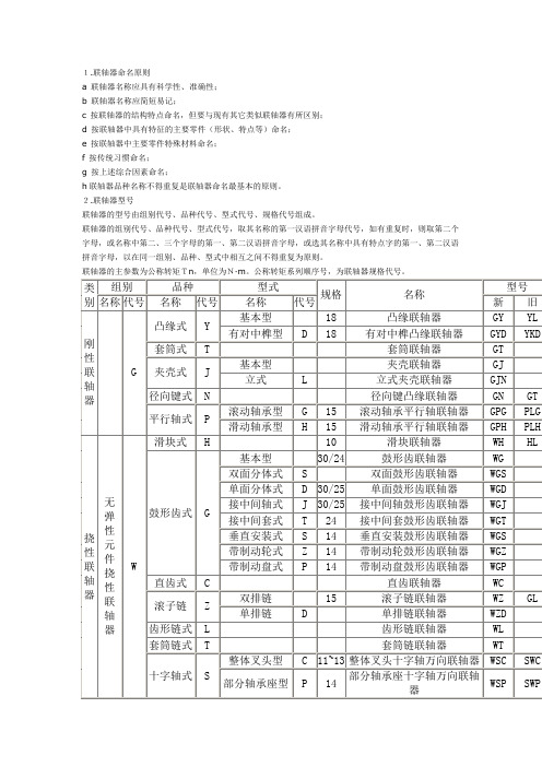
1.联轴器命名原则a 联轴器名称应具有科学性、准确性;b 联轴器名称应简短易记;c 按联轴器的结构特点命名,但要与现有其它类似联轴器有所区别;d 按联轴器中具有特征的主要零件(形状、特点等)命名;e 按联轴器中主要零件特殊材料命名;f 按传统习惯命名;g 按上述综合因素命名;h联轴器品种名称不得重复是联轴器命名最基本的原则。
2.联轴器型号联轴器的型号由组别代号、品种代号、型式代号、规格代号组成。
联轴器的组别代号、品种代号、型式代号,取其名称的第一汉语拼音字母代号,如有重复时,则取第二个字母,或名称中第二、三个字母的第一、第二汉语拼音字母,或选其名称中具有特点字的第一、第二汉语拼音字母,以在同一组别、品种、型式中相互之间不得重复为原则。
联轴器的主参数为公称转矩Tn,单位为N·m。
公称转矩系列顺序号,为联轴器规格代号。
联轴器新旧标准对照表序号现行标准号产品型号旧标准号1 JB/T8854.1-2001 GCLD JB/T8854.1-1999 ZBJ19012-89 JB/ZQ4380-862 JB/T8854.2-2001GⅠCLJB/T8854.2-1999ZBJ19013-89JB/ZQ4378-86 GⅡCLZ JB/T8854.3-1999ZBJ19014-89 JB/ZQ4379-863 JB/T8854.3-2001GⅠCLJB/T8854.2-1999ZBJ19013-89JB/ZQ4222-86 GⅠCLZJB/T8854.3-1999ZBJ19014-89JB/ZQ4223-864 JB/ZQ4644-1997 NGCL JB/ZQ4644-865 JB/ZQ4645-1997 NGCLZ JB/ZQ4645-866 JB/ZQ4186-1997 WG /7 JB/T7001-1993 WGP /8 JB/T7002-1993 WGC /9 JB/T7003-1993 WGZ /10 JB/T7004-1993 WGT /11 JB/ZQ4218-86 CL Q/ZB104-7312 JB/ZQ4219-86 CLZ Q/ZB105-7313 GB/T5272-2002 LM LMD LMS LMZ-ⅠLMZ-ⅡGB5272-85ML M14 GB/T4323-2002 LT LTZ GB4323-8415 GB/T5014-2003 LX LXZ GB5014-8516 GB/T515-2003 LZ LZJ LZD LZZ GB5015-85 ZL17 GB/T6069-2002 GL GB6069-8618 GB/T5843-2003 GY GYS GYH GB5843-8619 GB/T5844-2002 UL GB5844-8620 JB/ZQ4376-1997 YL JB/ZQ4376-8621 JB/ZQ4384-1997 WHL JB/ZQ4384-8622 JB/ZQ4018-1997 LLA LLB JB/ZQ4018-8623 JB/T5514-1991 TGL /24 JB/ZQ4389-1997 制动轮JB/ZQ4389-86常用联轴器款式及特点2007-12-28常用的联轴器款式有:金属螺旋弹簧联轴器,金属膜片联轴器,免键轴套,波纹管弹性联轴器,十字滑块弹性联轴器,梅花形弹性联轴器,尼无曲面体联轴器。
陕齿9JS图册

螺母M16×1.5 倒档中间轴垫圈 倒档止推垫圈 滚针轴承 倒档中间齿轮 杯形倒档垫圈 倒档中间轴 开槽平端紧定螺钉
机型
及用
量
单 位
RT11509C( 带取力
器)
易损C 常用B 非常用A
112511
备注
718000
1
件2
B
件2
B
件2
B
件2
B
件2
B
件2
B
件2
A
件2
B
六 、 上 盖 总 成
机型
及用
序 号
方头锥形螺塞
件1
B
8 12.7G100bGB-T308 钢球
件3
B
9 F96084-2
压缩弹簧
件2
B
10 F96085
压缩弹簧
件1
B
11 1642
操纵窗口衬垫
件1
B
12 11066
双头螺栓
件4
B
13 GB93-76
弹簧垫圈10
件2
B
14 Q361B10
2型六角螺母
件2
B
15 X-1-603
六角螺母3/8″-24
件8
B
底取力窗口盖
件1
B
底取力窗口衬垫
件1
B
方头锥形螺塞
件1
B
方头锥形螺塞
件1
B
变速器壳体
件1
A
序 号
图号
名称
机型
及用
量
单
易损C
位
常用B 备注 非常用A
序 号
图号
名称
1 16118 2 18701 3 14749 4 16748 5 14750 6 16750 7 16752 8 16754 9 16756 10 Q5280310 11 17109 12 18729
联轴器型式

GⅡCLZ1~13鼓形齿式联轴器JB/T 8854.2
Last Modified: 2004兺06懍14粧 10:05 湰屃
GⅡCLZ14~25鼓形齿式联轴器JB/T 8854.2
Last Modified: 2004兺06懍14粧 10:05 湰屃
GⅠCL1~14鼓形齿式联轴器JB/T 8854.3
Last Modified: 2004兺06懍14粧 10:05 湰屃
WS型双十字轴式万向联轴器JB/T 5901 1、3-半联轴器;2-叉形接头;4-十字轴;5-销钉;6-套 筒;7-圆柱销
Last Modified: 2004兺06懍14粧 10:05 湰屃
SWC型整体叉头十字轴式万向联轴器JB/T 5513 BH标准伸缩焊接式万向联轴器
Last Modified: 2004兺06懍14粧 10:05 湰屃
GⅠCL15~30鼓形齿式联轴器JB/T 8854.3
Last Modified: 2004兺06懍14粧 10:05 湰屃
GⅠCLZ1~14鼓形齿式联轴器JB/T 8854.3
Last Modified: 2004兺06懍14粧 10:05 湰屃
Last Modified: 2004兺06懍14粧 10:05 湰屃
紧箍夹壳式联轴器 1-紧箍环;2-夹壳;3-半环;4-钢丝挡圈
Last Modified: 2004兺06懍14粧 10:05 湰屃
滑块联轴器JB/ZQ4384 1、3-半联轴器;2-滑块;4-螺钉
Last Modified: 2004兺06懍14粧 10:05 湰屃
Last Modified: 2004兺06懍14粧 10:05 湰屃
GYS型凸缘联轴器GB/T5843
三爪联轴器标准

三爪联轴器标准三爪联轴器是一种常用的机械传动装置,其主要作用是实现两个或多个轴之间的传动。
作为一种标准化的产品,三爪联轴器有一系列的标准要求和参考内容。
下面是关于三爪联轴器标准的相关参考内容。
1. 三爪联轴器的基本结构和原理:三爪联轴器由外套、内圈、钢球和连心套四部分组成。
外套上有三个刀齿状凸缘,可以与内圈的刀齿状凹槽咬合,从而实现传动。
2. 三爪联轴器的分类:根据传动方式不同,三爪联轴器可以分为直通式、爪牙式和滚珠式三种。
直通式适用于低转速传动,爪牙式适用于高转速传动,滚珠式适用于超高转速传动。
3. 三爪联轴器的尺寸和容差要求:三爪联轴器应符合国家标准的相关尺寸和容差要求,例如直通式联轴器的最大偏斜角度应小于0.005弧度,爪牙式联轴器的轴向最大位移应小于0.2mm。
4. 三爪联轴器的材料和热处理要求:三爪联轴器的外套和内圈一般采用高强度钢材,经过淬火和回火热处理,以提高其硬度和耐磨性。
钢球一般采用轴承钢,连心套一般采用铸铁材料。
5. 三爪联轴器的静态和动态平衡要求:三爪联轴器在使用过程中要保持平衡,以减少振动和噪音。
在生产制造过程中,应进行静态和动态平衡测试,并按照国家标准的要求进行修正。
6. 三爪联轴器的使用和维护规范:三爪联轴器在使用前应进行试运转,确保正常工作。
在使用过程中,要注意润滑和防尘,定期检查联轴器的磨损情况,并及时更换磨损零件,以保证其传动效果。
7. 三爪联轴器的安全使用要求:三爪联轴器在运行过程中会产生很高的传动力矩,因此使用时要注意安全,避免发生卡爪、脱爪、断爪等事故。
在安装和拆卸联轴器时,要使用专用的工具,并按照操作规程进行。
8. 三爪联轴器的质量检验和验收标准:三爪联轴器在交付使用前需要进行质量检验和验收,检验项目包括外观检查、尺寸检查、传动试验等。
验收标准一般参照国家标准或行业标准的相关规定。
以上是对三爪联轴器标准的相关参考内容的介绍,三爪联轴器作为一种常用的机械传动装置,其标准化要求对于产品的设计、生产、使用和维护都具有重要的指导意义。
联轴器样本

4、复合固定方式:在联轴器的固定中,采用两种固定方式来进行联接固定 称为复合固定方式。
LK1
系列 Ⅰ、定位螺丝固定平行式
特点
·一体成型的金属弹性联轴器 ·适用较小力矩的轴联接
计算力矩
图3
图4
当知道电机的功率(KW),而未知电机的力矩时,则可按以下公式计算电机的力矩 电机力矩 T(N·m)= KW X 9550
rpm 其中,功率(KW)是所需要的实际或传动功率(如果未知,则使用电或机铭牌上的参数)。
常用电机功率与力矩转换一览表:
力矩
电机功率 (KW) 0.05 0.10 0.20 0.40 0.75 1.00 1.50 2.00 3.00 3.50 5.00 7.00
L K 9系 列 … … … … … … … … … … … … … … … … … … 胀 套 膜 片 联 轴 器
Ⅰ 、 单 节 胀 套 膜 片 联 轴 器 — — — — — — — — — — — — — — — — — —2 1 Ⅱ 、 多 节 胀 套 膜 片 联 轴 器 — — — — — — — — — — — — — — — — — —2 2
L K 2系 列 … … … … … … … … … … … … … … … … … … … … 弹 性 联 轴 器
Ⅰ 、 定 位 螺 丝 固 定 平 行 式 — — — — — — — — — — — — — — — — — —4 Ⅱ 、 定 位 螺 丝 固 定 螺 纹 式 — — — — — — — — — — — — — — — — — —5 Ⅲ 、 夹 紧 螺 丝 固 定 平 行 式 — — — — — — — — — — — — — — — — — —6 Ⅳ 、 夹 紧 螺 丝 固 定 螺 纹 式 — — — — — — — — — — — — — — — — — —7
联轴器样本
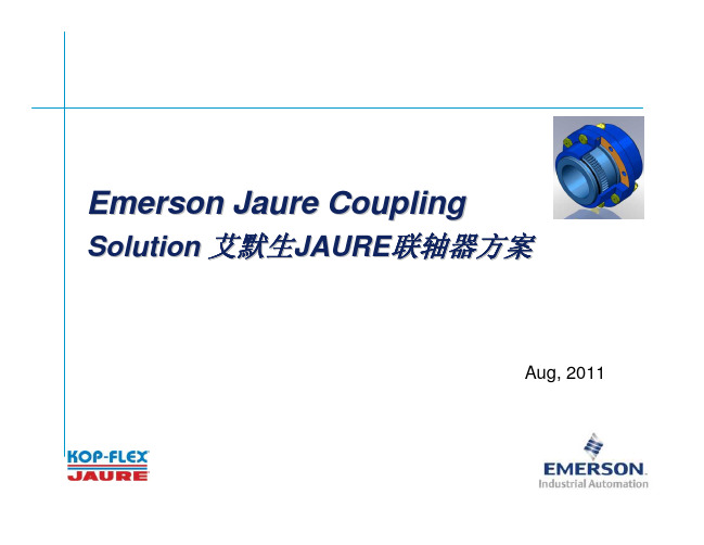
Emerson Couplings-Deep experience & testing Gear coupling Lubrication 艾默生联轴器-丰富的齿式联轴器润滑经验和测试
Why choose Kop-Flex/Jaure coupling 为何选择艾默生Kop-Flex/Jaure联轴器
Gear coupling 齿式联轴器特点 Improved material – 更好的材质选择 Improved heat treatment – 更合适的热处理选择 Higher torque capability – 更大的扭矩传递能力 Better lubrication with Kop-Flex coupling grease – 使用Kop-Flex 联轴器润滑脂后更佳的润滑效果 Better design and manufacturing which means Longer life time – 更好的设计和制造,意味着更长的使用寿命
Shear Coupling-Steel飞剪联轴器-钢铁 Underwater coupling-dredger水下联轴器-挖泥船
Winch coupling绞盘联轴器 Ball mill. Cement 球磨机-水泥
Emerson Couplings-Examples 艾默生联轴器-示例
Railway gear coupling 铁路齿式联轴器
Jaure 公司 (1958 - 2005)
Jaure – 艾默生动力传动旗 下子公司 (2005 - present)
Koopers 公司 -1928年
世界上第一台齿式联轴器专利图
两家公司累积的联轴器设计经验 > 135 年
3
cm-s-17-05
Torsionally highly elastic couplings for Diesel engines Hochdrehelastische Kupplungen für Antriebe mit DieselmotorenCENTAMAX®SB-SC-SD-SEPower Transmission Catalog CM-S-1 -0CENTAMAX-SThese torsional highly elastic CENTAMAX couplings were first introduced in 1980. Since that time they have been proved in numerous difficult applications.This coupling has been developed and tested following intensive research, calculations and market studies for the following areas of application:Drives subject to torsional vibration especially diesel engine drives, where the driven components have relatively small inertias and are required to run over a wide speed range from low idling rpm to full engine speed, free from dangerous resonances. For these applications it is desirable to shift the critical speeds far enough below engine idling speed so that the whole engine working speed range can be utilized without limitation.For such drives a torsionally very soft coupling is more desirable than a torsionally stiff coupling because the whole drive power train is then subjected to very low vibratory torques and is therefore more lowly stressed.CENTAMAX couplings are amongst the highest torsionally elastic couplings available on the market, with a torsional deflection of about 12° at nominal torque and about 30° at maximum torque for types SB.For the larger types, SC and SD, the torsional deflection is intentionally lower; it is about 6 – 8° at rated torque. Important Areas of Application:• Splitter gears, with several hydraulic pumps• Compressors• Ship propulsion• Generator sets• Pumping sets• Locomotives CENTAMAX-SDiese sehr drehelastische Kupplung wurde 1980 von der Firma CENTA Antriebe entwickelt und auf den Markt gebracht. Sie hat sich seitdem in tausenden schwierigen Einsatzfällen bestens bewährt.Nach eingehenden Überlegungen, Berechnungen und Marktstudien wurde diese Kupplung ganz gezielt für folgende Einsatzgebiete erprobt und entwickelt:Antriebe mit Drehschwingungen, insbesondere mit Dieselmotoren, wobei relativ kleine Trägheitsmassen über einen weiten Drehzahlbereich, möglichst bis zum niedrigen Leerlauf, ohne gefährliche Resonanzstellen angetrieben werden sollen. Es sollen also die Resonanzen auf niedrige Drehzahlen verschoben werden, so daß der gesamte Betriebsdrehzahlbereich des Motors nach Möglichkeit ohne Einschränkung genutzt werden kann.Für derartige Antriebe ist also eine extrem drehelastische Kupplung vorteilhafter als eine drehsteife Kupplung, weil dadurch der gesamte Antriebsstrang bei Betriebsdrehzahlen nur mit sehr geringen Dauerwechselmomenten belastet und somit sehr geschont wird.Die CENTAMAX gehört in dieser Hinsicht zu den hochelastischsten Kupplungen des Marktes. Bei der Bauform SB beträgt der Verdrehwinkel bei Nenndrehmoment je nach Ausführung ca. 12° und bei Maximalmoment ca. 30°. Bei den Bauformen SC und SD, die bewußt etwas drehsteifer ausgelegt wurden, beträgt der Verdrehwinkel bei Nenndrehmoment ca. 6 8°.Wichtige Einsatzgebiete:• Pumpenverteilergetriebe mit mehrerenhydraulischen Pumpen• Schraubenverdichter• Schiffsantriebe• Generatoren• Lokomotiven• KreiselpumpenIntroduction EinleitungFor generator sets the following characteristics of the CENTAMAX couplings are very advantageous:• Suited for blindfitting when set is flangemounted.• Free of backlash, even after long service time, therefore no creation of noise at idling or low load conditions.• Linear characteristic, that means resonances are not shifted by the load, important for sets which mustalso work satisfactorily under misfiring conditions.• Limitation of torque: at extreme overload (e.g. short circuit or wrong synchronizing), the coupling element will slip on the outer teeth and thereby protect engine and generator against dangerous overloads (slip torque is about 56 times rated torque). If this happens from time to time, the coupling will not be damaged. If it should happen frequently, then no dangerous broken metal pieces will be catapulted away, only harmless rubber particles which will neither hurt anybody nor cause further damage.CENTAMAX and CENTALOC are registered Trademarks of CENTA Antriebe.Bei Generatorantrieben sind folgende Eigenschaften der CENTAMAX Kupplungen besonders vorteilhaft:• Steckbar: bequeme Montage bei geflanschten Generatoren.• Spielfrei: auch nach längerer Laufzeit, keine Geräuschbildung durch Drehschwingungen bei Leerlauf oder geringer Teillast.• Lineare Kennlinie: d. h. keine Verschiebung der Resonanzen bei Teillast; wichtig für Antriebe, die auch bei Zylinderaussetzer betriebssicher sein müssen.• Drehmomentbegrenzung: Bei extremer Überlastung (z. B. durch Kurzschluß oder Fehlsynchronisierung) rutscht die Kupplung an der äußeren Verzahnung durch und schützt damit Motor und Generator vor Schäden durch Überlastung. (Durchrutschmoment ca.fünf bis sechsfaches Nenndrehmoment). Tritt dieser Fall gelegentlich auf, nimmt die Kupplung dabei keinen Schaden. Falls jedoch durch häufige Überlastung die Kupplung beschädigt wird, so werden keine gefährliche zerbrochene Metallteile weggeschleudert, sondern nur harmloser Gummiabrieb, der weder verletzen kann, noch Folgeschäden verursacht.CENTAMAX und CENTALOC sind eingetragene Warenzeichen der Firma CENTA Antriebe.Important characteristics and advantages• Torsionally very soft, no backlash.• Linear characteristic.• Torsional stiffness can be adjusted by choice of different Shore hardness discs.• Temperature resistant.• Dampens vibration and shock loads, accepts axial, radial and angular misalignment.• Good heat dissipation due to special airflow over disc.• Suitable for high speeds.• Hub accepts large bores.• No wearing parts, long life, reliable, maintenancefree.• Compact, slim design, input flange dimensions to SAE J620 for the connection of two shafts.• Easy installation, designed for blind fitting.• The rubber disc is free to float axially in the outer ring and no axial forces are generated by the transmission of torque.Wichtige Eigenschaften und Vorteile:• sehr drehelastisch, spielfrei• lineare Kennlinie• durch verschiedene Shorehärten kann die Drehsteifigkeit den schwingungstechnischen Erfordernissen angepaßt werden• dämpft Schwingungen und Stöße, gleicht axiale, radiale und winkelige Fluchtungsfehler aus.• allseitige Belüftung (Kühlung) der Gummischeibe• temperaturbeständig• geeignet für hohe Drehzahlen• große zulässige Bohrungen• verschleißfrei, langlebig, betriebssicher, wartungsfrei • kompakte, kurze Bauform: Anschlußmaße nach SAE J620 oder zur Verbindung von 2 Wellen• einfache Montage, axial steckbar• axial frei beweglich und frei von drehmomentbedingten axialen Kräften.KonstruktionDie Leistungsübertragung geht bei der CENTAMAX üblicherweise von einem Motorschwungrad über einen Leichtmetallring und von dort über eine Verzahnung formschlüssig auf eine Gummischeibe und von dieser auf die anvulkanisierte innere Abtriebsnabe.Der scheibenförmige Gummikörper ist so ausgebildet, daß über möglichst weite Bereiche eine gleichhohe Schubspannung auftritt, um einerseits möglichst große Verdrehwinkel zu erzielen und andererseits Spannungsspitzen zu vermeiden.An der inneren Vulkanisationsfläche und an der äußeren Verzahnung ist jedoch der Querschnitt überproportional ausgelegt, um dort noch niedrigere spezifische Belastungen zu erhalten. Durch diese niedrige spezifische Belastung ist die Vulkanisation der inneren Nabe sehr niedrig beansprucht, weitaus niedriger als üblich, und somit sehr betriebssicher.Das hier beschriebene Konstruktionsprinzip: Vulkanisation an innerer Nabe — Verzahnung an äusserer Nabe — hat folgende Vorteile:Große elastische Länge, somit große Verdrehwinkel, unproblematische, verschleißfreie und spielfreie Überleitung der Kräfte vom Gummi zu den metallischen Anschlußteilen, einfache, kompakte, betriebssichere und langlebige Bauweise.DesignA rubber disc which has moulded teeth on its outside diameter is engaged into an internally toothed aluminium ring that is usually driven by a flywheel. The centre of the rubber disc is vulcanized to an inner driven hub.The rubber disc has a designed shape to ensure that equal stress occurs over most of its section, thus providing a large torsional angle and avoiding high stress in these areas.However, on the inner vulcanized surface and on the outer teeth at these points, the loading of the rubber is reduced to a much lower level than is normally accepted, thus providing a very reliable drive.The design described above — vulcanization to the inner hub, with tooth engagement on the outer ring — has the following advantages:Long elastic length providing high torsional deflection angle, wear and backlashfree rubber connection between inner and outer hubs, ensures troublefree operation — simple, compact, reliable and long lastingClassificationCENTAMAX couplings can be supplied in accordance with the requirements of the leading classification societies. However, if this is required, it must be specified at the time of the initial enquiry and when ordered. The couplings have general type approval from many important societies. Please ask for details.If required, a …failsafe“ design of the coupling can be supplied (Page 18, figure 2). KlassifikationDie Kupplungen können gemäß den Klassifikationsvorschriften der verschiedenen Klassifikationsgesellschaften geliefert werden. Von den wichtigsten Gesellschaften liegt außerdem die allgemeine Typengenehmigung vor. Einzelheiten auf Anfrage.Falls vorgeschrieben, können die Kupplungen auch mit Durchdrehsicherung geliefert werden (Seite 18, Bild 2).Design SizesThe complete range is now comprised of 15 sizes for the torque range from 100 48000 Nm. This means it ranges from 1cylinder engines with a few kW up to large multicylinder engines with about 3000 kW capacity. Types 4000 SD and 18000 SD (D means double) are comprised of 2 parallel acting elements, in order to increase the torque.BaugrößenDie komplette Baureihe besteht zur Zeit aus 15 Baugrössen für den Drehmomentbereich von 100 bis 48000 Nm, d. h. sie reicht vom kleinen 1ZylinderMotor mit wenigen kW bis zu vielzylindrigen Motoren mit ca. 3000 kW Leistung. Die Bauformen 4000 – 18000 SD sind doppelt angeordnete Baugrößen zur Verdoppelung des Drehmomentes.MaterialsInner Hub: Steel with minimum tensile strength of 600N/mm2 (8500 psi).Outer ring: High grade cast aluminium alloy.Flexible disc: High quality, natural rubber (NR) in different Shore hardnesses, temperature resistant.For applications with high ambient temperature, especially in bell housings, we recommend the high temperature resistant version with Silicon elastomer (SI).Allowable ambient temperature:NR: –45°C up to + 90°CSI: –45°C up to +120°C WerkstoffeInnere Naben: Stahl von mindestens 600 N/mm2Zugfestigkeit (8500 psi).Äußerer Ring: Hochwertiger AluminiumgußElastische Scheibe: Hochwertige, temperaturbeständige, dämpfende Naturkautschukmischung, in verschiedenen Shorehärten lieferbar.Für Einsätze mit hoher Umgebungstemperatur, insbesondere in Flanschglocken, ist die hochtemperaturbeständige Ausführung in Silicon (SI) zu empfehlen.Zulässige Umgebungstemperatur:NR: 45°C bis + 90°CSI: 45°C bis + 120°CDimensionsThe outer driving ring is dimensioned to mount direct to flywheels machined to SAE standard J 620. Most sizes are available with various SAE flanges, thus providing the correctly dimensioned and sized coupling for every application.Other mounting dimensions or special designs are possible if required. The couplings are extraordinarily short in axial direction. The smaller sizes up to and including size 1200 with SAE 11,5" nominal flange fit into the contours of the SAE housing. The hub dimensions can be varied as necessary.AbmessungenDie äußeren Anschlußmaße der Flanschbauformen entsprechen der SAENorm J 620 bzw. DIN 6281 für Schwungräder. Die meisten Baugrößen sind mit verschiedenen SAEAbmessungen lieferbar, damit für alle Einsatzfälle die maßlich und leistungsmäßig richtig abgestimmte Kupplung zur Verfügung steht. Darüber hinaus sind Sonderbauformen oder abweichende Abmessungen gegebenenfalls möglich. Die Kupplung ist in axialer Richtung außerordentlich kurzbauend. Die kleineren Größen bis einschließlich der Grösse 1200 mit SAE 11,5"Anschluss liegen innerhalb der Kontur des SAESchwungradgehäuses. Die Naben aller Bauformen können in weiten Grenzen abgewandelt und den speziellen Erfordernissen angepaßt werden.Hub Design Naben-BauformenFlywheel — ShaftType SB — Sizes 1 0– 00The driven inner hub consists of two pieces, the vulcanized steel ring and the inner steelboss.These two parts are bolted together and the drive is transmitted by the friction force created by the axial bolts, drawing the tapered hub onto a mating taper in the element.This connection is very conservatively dimensioned but it can be easily disassembled if the coupling has to be removed. The steel ring to which the element is vulcanized creates very high inward pressure acting on the inner driven hub. In order to utilize this pressure, the driven hub can be slotted in an axial direction. This allows the driven hub to be compressed and provides a very strong backlash free connection between the driven hub and driven shaft. This effect can be used equally well on parallel cylindrical shafts with keys or splined shafts, and is absolutely free of backlash or wear. We call this feature CENTALOCSclamping.Refers to all sizes: Further figures after the type designation refer to the length of the inner hub (boss) or to special hubs. e. g., SB 1 means standard length of hub, SB 2 means longer hub a.s.o. Verbindung Schwungrad – Welle Bauform SB — Größen 1 0– 00Die innere Abtriebsnabe ist zweiteilig ausgeführt, sie besteht aus dem einvulkanisierten Stahlring und der eigentlichen inneren Stahlnabe.Diese beiden Teile sind über einen Konus reibschlüssig miteinander verbunden; die Anpreßkraft wird durch Schrauben auf den Konusring aufgebracht. Diese Verbindung ist einerseits sehr sicher dimensioniert, andererseits aber leicht lösbar, falls die Kupplung demontiert werden muß. Durch den Stahlring wird über den Konus ein sehr hoher, nach innen gerichteter Druck auf die innere Nabe aufgebracht. Um diesen radialen Druck auszunutzen, kann die innere Nabe mit einem Längsschlitz versehen werden. Dann ergibt sich durch das Zusammenpressen der inneren Nabe gleichzeitig eine sehr feste und spielfreie Verbindung zwischen Nabe und Welle. Dieser Effekt kann sowohl bei normalen zylindrischen Wellen und insbesondere bei Wellen mit Vielkeil oder Evolventenverzahnung vorteilhaft eingesetzt werden, weil sich dadurch eine völlig spielfreie, d.h. verschleißfreie Verbindung ergibt, genannt CENTALOCSKlemmung. Weitere Ziffern nach der Bauform bezeichnen die Nabenlänge bzw. Sondernaben. Zum Beispiel: SB 1 bedeutet Standardnabenlänge; SB 2 bedeutet verlängerte Nabe, usw.Type SC — Sizes 00–18000A potshaped flange made of spheroidal cast iron is vulcanized into the rubber element. This flange is bolted with generously dimensioned bolts to the inner boss.Depending upon the position (arrangement) of the rubber element, two different lengths are achieved with the same parts.Short version: SCALong version : SCB Bauform SC- Größen 00–18000In das Gummielement einvulkanisiert ist ein topfförmiger Flansch aus Sphäroguß. Dieser Flansch wird über reichlich dimensionierte Schrauben reibschlüssig mit der inneren Stahlnabe verbunden.Je nach Anordnung des Gummielementes ergeben sich mit den gleichen Teilen2 verschiedene Baulängen:kurze Bauform: SCAlange Bauform: SCBThis type is comprised of 2 rubber elements parallel acting which are bolted to the hub in order to double the torque capacity. This version is basically possible for the sizes 2800, 4000, 8000, 12000 and 18000.Bauform SDGrößen 000, 8000 und 18000Bei dieser Bauform werden 2 Gummielemente parallel angeordnet mit der Nabe verschraubt, um das übertragbare Drehmoment zu verdoppeln. Diese Anordnung ist grundsätzlich möglich für die Baugrößen 2800, 4000, 8000, 12000 und 18000.Types SBE, SCE and SDE Sizes 0–18000Flywheel - shaft connectionThese versions are particularly advantageous on larger sizes of couplings. The rubber element can easily and quickly be changed without disturbing the coupled shafts in these types on independently mounted, nonflanged sets, provided that the flywheel housing does not protrude too far over the coupling unit. If they protrude too much, then the coupling element can nevertheless be changed radially, if an additional spacer ring is provided between the driven hub and element, as shown on Picture 4, Page 18.The designation SDE indicates couplings with 2 elements, Sizes 4000 SDE, 8000 SDE, 12000 SDE and 18000 SDE.For the sizes 240 2400 SBE, the vulcanized hub in the element is different it has additional taped holes.For the sizes 2800 18000D, the element is identical to other types, but an additional steel clamp ring is used.Bauform SBE, SCE und SDE Größen 0–18000Verbindung Schwungrad – Welle Bei dieser Bauform für frei aufgestellte, nicht geflanschte Aggregate kann das Gummielement bequem und schnell ausgewechselt werden, ohne daß die gekuppelten Aggregate bewegt werden müssen. Voraussetzung ist dabei nur , daß das Schwungrad bzw. Schwungradgehäuse nicht zu weit über die Kupplung ragt. Sollten Schwungrad oder Schwungradgehäuse jedoch zu weit über die Kupplung ragen, dann ist die Kupplung trotzdem radial tauschbar , wenn ein zusätzlicher Distanzring zwischen Nabe und elastischem Element angeordnet wird. (Siehe Seite 18, Bild 4).Diese Bauform ist vor allem für grössere Aggregate wichtig. Die Bezeichnung SDE gilt für die Baugrößen 4000 SDE, 8000 SDE, 12000 SDE und 18000 SDE.Bei den Baugrößen 240 2400 SBE unterscheidet sich die in das Gummielement einvulkanisierte innere Nabe von den übrigen Bauformen, sie hat zusätzliche Gewindebohrungen. Bei den Baugrössen 2800 18000D ist das Gummielement identisch mit den übrigen Bauformen, es wird lediglich ein Ring mit den entsprechenden Gewindebohrungenhinzugefügt.Types SBEW, SCEW, SDEWRadial assembly/disassembly types for shaft-to-shaft drivesSizes 0–18000This type is for the connection of 2 shafts where the element can be removed radially without disturbing the driving or driven shafts. Here single cylindrical steel bolts are used instead of the aluminium teeth in the outer ring which engage with the toothed rubber disc, exept on the size 8000 SDEW (with double elements) where an outer aluminium ring is used.Types SBW, SCW, SDWSizes 0–18000Shaft to shaftThis type is shorter and lower in price than the dropout types. The coupling halves can be assembled radially — like a ‘threepiece’ coupling — but the element cannot be changed without disturbing the shafts.Special TypesIn addition to the standard types shown here, we have developed many special types.Samples are shown on Page 18.Bauform SBEW, SCEW und SDEWGrößen 0–18000Verbindung Welle – WelleDiese Bauform dient zur Verbindung von 2 Wellen, und sie ermöglicht gleichfalls den Wechsel der Elemente ohne Verschiebung der gekuppelten Aggregate (wie Bauform SE).Anstelle des verzahnten äußeren Rings sind hier einzelne zylindrische Bolzen angeordnet, die in die Verzahnung des Gummielementes eingreifen.Nur bei der Größe 8000 SDEW mit doppeltem Element ist der entsprechende äußere Aluminiumring (wie SAE 18) angeordnet.Bauform SBW, SCW und SDWGrößen 0–18000Verbindung Welle – WelleDiese Wellenbauform ist kürzer und preiswerter als die radial tauschbare Bauform EW. Die Kupplung kann radial (quer) montiert werden wie eine …dreiteilige“ Kupplung, jedoch kann das Gummielement in eingebautem Zustand der Kupplung nicht gewechselt werden.SonderbauformenNeben den hier gezeigten StandardBauformen haben wirzahlreiche Sonderbauformen entwickelt.Beispiele finden Sie auf Seite 18.The following wellknown formula can be used for the preliminary coupling selection, based on transmitted torque: T = · 9550Provided that: T < T KN · S t1P = Power [kW]n = Speed [rpm]T = Transmitted torque [Nm]T KN = Nominal torque of coupling [Nm]In closed flywheel housings there is always an ambient temperature of at least 60°C 70°C.For reliable coupling selection on drives subject to torsional vibration (diesel engines, piston compressors etc.) a torsional vibration analysis is necessary.If requested, we will carry out the calculations (free of charge) using our own computer program, upon receipt of the drive details.Eine überschlägige Zuordnung, ausgehend vom zu übertragenden Drehmoment, kann zunächst nach folgender bekannter Formel erfolgen:T = · 9550Bedingung ist: T < T KN · S t1P = Leistung [kW]n = Drehzahl [min 1]T = Drehmoment [Nm]T KN = Nenndrehmoment der Kupplung [Nm]In geschlossenen Schwungradgehäusen muß immer mit Temperaturen von mindestens 60°C bis 70°C gerechnet werden.Für eine betriebssichere Auslegung bei Antrieben mit Drehschwingungen (Dieselantriebe, Kolbenmaschinen) ist jedoch immer eine Drehschwingungsrechnung erforderlich. Die dazu erforderlichen Daten der Kupplungen finden Sie in diesem Katalog. Wir führen für Sie auch gern solche Drehschwingungsrechnungen durch, wofür wir eigene Computerprogramme entwickelt haben.Selection of CENTAMAX couplingsAuslegung der CENTAMAX-Kupplun-genP nP nSince these couplings are normally only applied to drives running over critical, i.e. work speeds above resonance speeds, the following details must be checked:• Where are the resonance speeds? There must be sufficient distance between the main resonance speed and lowest working or idling speed.• Is the maximum vibratory torque when passing throughresonance lower than the coupling value for T Kmax ? • Is the continuous vibratory torque T W at working speedlower than the allowable vibratory torque T KW of the coupling, considering the frequency factor S f and the temperature factor S t2 , or is the total loss of energy P V (by damping) from all the single orders lower than the allowable loss of energy P KV , considering the temperature factor S t2?Da diese Kupplung sinnvollerweise nur bei überkritischem Betrieb eingesetzt wird, d. h. die Betriebsdrehzahlen liegen oberhalb der kritischen Drehzahlen (Resonanzen), sollten folgende Kriterien überprüft werden:• Lage der Resonanzdrehzahlen, d. h. ist genügend Abstand der Resonanzen zur niedrigsten Betriebsdrehzahl bzw. Leerlauf gegeben? • Sind die beim Durchfahren der Resonanzen auftretenden Wechseldrehmomente zulässig, d. h. kleiner als T Kmax der Kupplung? • Ist das im Betrieb vorhandene Dauerwechseldrehmoment zulässig, d. h. kleiner als das zul. Dauerwechseldrehmoment T KW der Kupplung, unter Berücksichtigung des Frequenzfaktors S f und des Temperaturfaktors S t2, bzw. ist die Summe der Verlustleistungen P V aus den einzelnen Ordnungen kleiner als die zulässige Verlustleistung P KV , unter Berücksichtigung des Temperaturfaktors S t2?The CENTAMAX couplings are robust and reliable, but with the wrong torsional situation every coupling, and possibly the whole power train, is in danger . Therefore it is of the utmost importance to ensure that torsional vibration calculations are made at the beginning of the coupling selection procedure.The technical data on the next page refers only to the couplings as such. This is, for example, no indication for ensuring that the bolts attaching the flywheel flange onto the flywheel can always transmit these torques, especially when relatively small flanges are used. In these cases additional or larger bolts and/or dowel pins must be provided. If there are several SAE flange fittings provided in the flywheel, the largest one should be preferred. It is the responsibility of the customer to check this point as well as the other points such as the dimensions of shafts and keys, or any other connection to the coupling.The CENTA range of couplings is one of the broadest ranges available with couplings available in many stiffness grades from torsionally very stiff to torsionally very soft. Thus, using our worldwide experience in solving torsional vibration problems and our awareness of its importance, we can recommed the most suitable coupling for almost any application without compromising design standards. This ensures reliable and troublefree coupling operation.Die CENTAMAXKupplungen sind robust, aber bei falscherDrehschwingungslage ist jede Kupplung gefährdet, unter Umständen der gesamte Antriebsstrang. Darum ist es so wichtig, die Drehschwingungslage zu berechnen und von Anfang an eine geeignete Kupplung vorzusehen.Die folgenden technischen Daten beziehen sich nur auf die Kupplung als solche. Damit ist z. B. nicht ausgesagt, ob die Verschraubung des SAEFlansches am Schwungrad immer diese Drehmomente übertragen kann, insbesondere dann, wenn relativ kleine Flansche eingesetzt werden. Dann müssen gegebenenfalls zusätzliche oder grössere Schrauben und/oder Stifte vorgesehen werden. Stehen mehrere SAEAnschlüsse zur Wahl, sollte der grössere vorgezogen werden. Die Überprüfung dieses Punktes, ebenso wie die Verantwortung für die Dimensionierung von Wellen und Paßfedern oder sonstigen Verbindungen mit der Kupplung liegt beim Anwender .Die Fa. CENTA bietet eines der umfangreichsten Kupplungsprogramme mit Kupplungen aller Drehsteifigkeitsgrade, von sehr drehsteif bis extrem drehelastisch. Daher , und weil wir speziell Erfahrung mitDrehschwingungenhaben, können wir für fast jeden Fall die objektiv richtigeKupplung für betriebssichere Antriebe vorschlagen.。
爪式联轴器
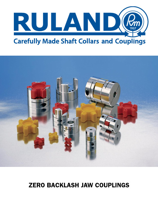
Introduction
Ruland Manufacturing Co., Inc. has been supplying carefully made products since 1937. We have manufactured everything from bicycle pumps to high pressure valves, including the valve that pressurized the spacesuit of the first American to walk in space. In recent years, all of our expertise has been devoted to making the best shaft collars and couplings available. Zero backlash jaw couplings are a new addition to our expanding line of motion control coupling products.
2
JC
ZERO BACKLASH JAW cOUPLING
JS
Inch DIMENSION SERIES
HUBS
part number
clamp style
Set Screw style
JC10-2-A JC10-3-A JC10-4-A JC12-3-A JC12-4-A JC12-5-A JC16-4-A JC16-5-A JC16-6-A JC16-8-A JC21-5-A JC21-6-A JC21-8-A JC21-10-A JC26-6-A JC26-8-A JC26-10-A JC26-12-A JC32-8-A JC32-10-A JC32-12-A JC32-14-A JC32-16-A JC36-8-A JC36-10-A JC36-12-A JC36-14-A JC36-16-A JC36-18-A
齿式联轴器

172 132 212 167 82 45
Hale Waihona Puke 20-172 132 212 167 112 -
5
20
29
34
142 107 290 272245225176 136 81 30 120 172 132 5 5
79.5 55.8 0.71 20
0.46
0.75
0.55
100、110、 212 167
120、125 65、70、71、 75 80、85、90、 WGT9 25000 95 100、110、 120、125 130、140 75 80、85、90、 95 WGT10 40000 100、110、 120、125 142 107 38
转动惯量 I /Kg·m Ⅰ
2
润滑脂/kg Ⅰ Ⅱ
Ⅱ
12、14 WGT1 710 16、18、19 20、22、24
32 42 52
30 - 50 30 75 2014 - 5.66 4.86 0.008 10 4 0.0063 0.085 0.04
25、28 30、32、35、 38 40、42 22、24 25、28 WGT2 1250 30、32、35、 38 40、42、45、 48、50、56 22、24 25、28 30、32、35、 38 WGT3 2500 40、42、45、
172 132
315 305265245190 140 88 30 155 5 5 28
106.5 80.5 1.05
0.77
1
0.79
212 167 252 202 142 28
38
172 132 355 340300280225 165 98 30 155 5
