Agilent8169A偏振控制器
Agilent-眼图、抖动、相噪
Agilent——眼图、抖动、相噪随着数据速率超过Gb/s水平,工程师必须能够识别和解决抖动问题。
抖动是在高速数据传输线中导致误码的定时噪声。
如果系统的数据速率提高,在几秒内测得的抖动幅度会大体不变,但在位周期的几分之一时间内测量时,它会随着数据速率成比例提高,进而导致误码。
新兴技术要求误码率(BER),亦即误码数量与传输的总码数之比,低于一万亿分之一(10-12)。
随着数据通信、总线和底板的数据速率提高,市场上已经出现许多不同的抖动检定技术,这些技术采用各种不同的实验室设备,包括实时数字示波器、取样时间间隔分析仪(TIA)、等时取样示波器、模拟相位检波器和误码率测试仪(BERT)。
为解决高数据速率上难以解决的抖动问题,工程师必需理解同步和异步网络中使用的各种抖动分析技术本文重点介绍3 Gb/s以上新兴技术的数据速率。
低于3 Gb/s的实时示波器可以捕获连续的数据流,可以同时在时域和频域中分析数据流;在更高的数据速率上,抖动分析要更具挑战性。
本文将从数字工程师的角度,介绍应对SONET/SDH挑战的各种经验。
抖动分析基本上包括比较抖动时钟信号和参考时钟信号。
参考时钟是一种单独的黄金标准时钟,或从数据中重建的时钟。
在高数据速率时,分析每个时钟的唯一技术是位检测和误码率测试;其它技术则采用某种取样技术。
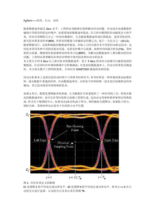
如图1所示,眼图是逻辑脉冲的重叠。
它为测量信号质量提供了一种有用的工具,即使在极高的数据速率时,也可以在等时取样示波器上简便生成。
边沿由‘1’到‘0’转换和‘0’到‘1’转换组成,样点位于眼图的中心。
如果电压(或功率)高于样点,则码被标为逻辑‘1’;如果低于样点,则标为‘0’。
系统时钟决定着各个位的样点水平位置。
图1: 具有各项定义的眼图E1是逻辑‘1’的平均电压或功率电平,E0是逻辑‘0’的平均电压或功率电平。
参考点t = 0在左边的交点进行选择,右边的交点及其后是位周期TB。
Eye Crossing Point: 眼图交点Left Edge: 左沿Right Edge: 右沿Nominal Sampling Point: 标称样点幅度噪声可能会导致逻辑‘1’的电压或功率电平垂直波动,低于样点,导致逻辑‘1’码错误地标为逻辑‘0’码,即误码。
Agilent-GCMS培训(完整版330页)

进样口和检测器出口
气路连接口
电缆连接口
电源连接口
炉箱冷却风进口
Agilent 7890A 键盘介绍
*
运行按键
气相部件按键
数字按键
信息按键
方法存储和自动运行按键
维护按键
*
Agilent GC6890前视图
*
Agilent GC6890侧后视图
*
即时功能键 功能键 快捷键 信息键 数字键 多功能键 方法存贮与自动 运行
MSD
10-5 Torr
<2 mL/min
760 Torr
0.5 - 15 mL/min
传输线
*
气相色谱和质谱的联用技术——传输线
传输线
涡轮泵
自动进样器
离子源
炉箱
*
色谱柱
流量 控制器
稳压器
空气
氢气
载气
分子筛
脱水管
固定
进样口
检测器
电子部件
PC
限流器
典型的气相色谱
*
分子筛 P/N 5060-9084
(0 to 218 V)
Signal Out
EM Voltage
电子倍增器
电压有使用上限(3000伏) 电压的提高,可以提高检测器的信号
*
电子倍增器的寿命曲线
*
提供足够的平均自由程 提供无碰撞的离子轨道 减少离子-分子反应 减少背景干扰 延长灯丝寿命 消除放电 增加灵敏度
为什么MS需要真空
空气压力应为 80 psi。
推荐管线压力
氢气压力应为 60 psi。
载气必须通过控制形成恒定的压力和恒定的流量。上下游控制器压差保持1公斤以上。
ARTISAN技术组-设备说明书

ErrataTitle & Document Type:Manual Part Number:Revision Date:HP References in this ManualThis manual may contain references to HP or Hewlett-Packard. Please note that Hewlett-Packard's former test and measurement, semiconductor products an d chemical analysis businesses are now part of Agilent Technologies. We have made no changes to this manual copy. The HP XXXX referred to in this document is now the Agilent XXXX. For example, model number HP8648A is now model number Agilent 8648A.About this ManualWe’ve added this manual to the Agilent website in an effort to help you support your product. This manual provides the best information we could find. It may be incomplete or contain dated information, and the scan quality may not be ideal. If we find a better copy in the future, we will add it to the Agilent website.Support for Your ProductAgilent no longer sells or supports this product. You will find any other available product information on the Agilent Test & Measurement website:Search for the model number of this product, and the resulting product page will guide you to any available information. Our service centers may be able to perform calibration if no repair parts are needed, but no other support from Agilent is available.16500B/16501A Logic Analysis System User's Reference 16500-97010April 1994U s er’s Ref er encePubl i c a t i on num be r16500-97010Fi r s t edi t i on,Apr i l1994For Sa f e t y i nf or m a t i on,W a r r a nt i es,a nd Reg ul a t or yi nf or m a t i on,s ee t he pa ges be hi nd t he i nde x©Copyr i g ht Hewl et t-Pac ka r d Com pa ny1987,1990,1993,1994 Al l Ri ght s Re s er v edHP 16500B/16501ALogi c Anal ys i s Sys t emI n Thi s BookW el c om e t o t he He wl et t-Pac ka r d Logi c Ana l y s i s Sys t em!The HP 16500B Logi c Ana l y s i s Sys t em i s des i gned t o be t heea s i es t s ys t em t o us e,ev e r.I t s m odul a r des i gn a l l ows you t o c onf i gur e i t wi t h j us t t he m ea s ur em ent m odul es you need now, yet a dd ot he r m odul es l a t e r.Thi s r e f er enc e expl a i ns t he oper a t i on of t he s ys t em m a i nf r a m e a nd I nt er m odul em enus.Al s o i nc l ude d i s i nf or m a t i on ont he m os t c om m on s ys t em opt i ons.O r gani zat i onW hen you or der t he HP 16500B,you get t wo bi nder s(one i s ext r a f or l a t e r us e). The m a i nf r a m e r e f er enc e i nf or m a t i on i s f ound be hi nd t he f i r s t t a b "HP 16500BM a i nf r a m e."I nf or m a t i on on t he opt i ona l keyboa r d,m ous e,a nd t he HP 16501A Expa ns i onFr a m e i s f ound behi nd t he s ec ond t a b, "Sys t em Opt i ons."As you a c c um ul a t eot her s ys t em opt i ons,pl a c e t hes er ef er e nc es behi nd t hi s t a b.Behi nd t he t hi r d t a b "Com m on M odul e Oper a t i ons"i s i nf or m a t i on c om m on t om os t m odul es,l i ke i ns t a l l i ng m odul e s,us i ng s ym bol s,a nd a s s i gni ng l a bel s.As you pur c ha s e a ddi t i ona l m ea s ur em ent m odul es,pl a c e t hei r r ef er e nc es a t t heba c k of t hi s bi nde r or i n t he s e c ondbi nder.W hat i s i n t he H P 16500B Us er’s Ref er ence?•Cha pt e r1 i nt r oduc es t he HP 16500B by s um m a r i z i ng i t s f ea t ur es.•Cha pt e r2 di s c r i bes t he m a i nf r a m e’s Sys t em Conf i g ur a t i on m e nu.•Cha pt e r3 di s c r i bes t he HP-I B a nd RS-232C i nt er f a c es.They a r e us ed f or pr i nt i ng s c r eens a nd c om put e r c ont r ol l ed m ea s ur em ent s.•Cha pt e r4 expl a i ns how t o pr i nt s c r eens t o v a r i ous g r a phi c s pr i nt er s.•Cha pt e r5 di s c r i bes t he f l exi bl e di s k a nd ha r d di s k ope r a t i ons.•Cha pt e r6 des c r i bes t he Sys t em Ut i l i t i es m enu.Adj us t m ent s t o t he r ea l-t i m e c l oc k,t ouc h c a l i br a t i on,a nd s c r een c ol or s a r e m a de her e.•Cha pt e r7 expl a i ns how t o m a ke i nt er m odul e m ea s ur em ent s.•Cha pt e r8 l i s t s t he i ns t r um ent s pec i f i c a t i ons a nd c ha r a c t er i s t i c s.•Cha pt e r9 expl a i ns t he gener a l i ns t r um ent m a i nt ena nc e a nd r epa c ki ngi nf or m a t i on.Al s o i nc l uded i s a des c r i pt i on of t he s el f-t es t t ha t i sper f or m ed when t he i ns t r um e nt i s t ur ned on.•Cha pt e r10 des c r i bes a l l s y s t e m a nd di s k er r or m es s a ges.W hat i s i n t he Sys t em O pt i ons?•Cha pt e r1 expl a i ns t he key boa r d a nd m ous e opt i ons.•Cha pt e r2 des c r i bes t he HP 16501A Expa ns i on Fr a m e opt i on.Ev en t hough you m a y not ha v e pur c ha s e d t he s e opt i ons yet,keep t hi si nf or m a t i on f or pos s i bl e f ut ur e us e.W hat i s i n t he C om m on M odul e O per at i ons?•Cha pt e r1 des c r i bes a s s i gni ng l a bel s.•Cha pt e r2 des c r i bes us i ng s ym bol s.•Cha pt e r3 expl a i ns t he gener a l i ns t a l l a t i on f or i ndi v i dua l m odul es.W her e t o go nextI f you ha v en’t a l r ea dy r ea d Se t t i ng Up The HP 16500 Logi c Anal ys i sSys t e m,pl ea s e r ea d i t be f or e c ont i nui ng.M S-DOS®i s a US r egi s t er e d t r a de m a r k of M i c r os of t Cor por a t i on.Cont ent sH P 16500BM ai nf r am e1W hat I s t he H P 16500B Logi c A nal ys i s Sys t em?Ke y Fea t ur es 1–3Opt i ona l Fea t ur es 1–3Us er I nt er f a c es1–4Def a ul t Conf i gur a t i ons 1–4Ac c es s or i es Suppl i ed 1–5Ac c es s or i es Av a i l a bl e 1–52The Sys t em Conf i gur at i on M enuGe t t i ng i nt o t he Sys t em Conf i g ur a t i on M enus 2–4La yout of t he Sy s t e m Conf i gur a t i on M enus 2–5Sl ot Des i gna t or s 2–63C onf i gur i ng t he H P-I B and RS-232CConf i gur i ng t he HP-I B I nt er f a c e3–4Conf i gur i ng t he RS-232C I nt er f a c e3–5Conf i gur i ng t he I nt er f a c e f or a Cont r ol l er or Pr i nt er 3–84C onnect i ng a Pr i nt erConne c t i ng HP-I B Pr i nt e r s 4–3Conne c t i ng RS-232C Pr i nt e r s 4–6Conne c t i ng t o Ot he r Hewl et t-Pa c ka r d Pr i nt er s 4–9Pr i nt i ng t he Di s pl a y 4–11Cont ent s–1Contents5The D i s k D r i ve M enusAc c es s i ng t he Di s k M enus 5–5I ns t a l l i ng a Fl exi bl e Di s k 5–6Sel e c t i ng a Di s k Oper a t i on 5–7Loa di ng a Fi l e 5–8For m a t t i ng a Di s k 5–10St or i ng Fi l es on a Di s k 5–12Rena m i ng a Fi l e 5–15Aut ol oa di ng a Fi l e 5–17Pur gi ng a Fi l e 5–19Copy i ng a Fi l e 5–20Pac ki ng a Di s k 5–22Dupl i c a t i ng a Di s k 5–23M a ki ng a Di r e c t or y 5–24Cha ngi ng t he Di r ec t or y 5–25Cr ea t i ng a Sys t em Fl e xi bl e Di s k 5–266The Sys t em Ut i l i t i es M enuThe Touc h a nd Sound Fi el ds 6–4Touc h Ca l i br a t i on 6–4Set t i ng t he Rea l-t i m e Cl oc k 6–6Tur ni ng t he Sound On/Of f 6–7Di s pl a y Col or Se l ec t i on 6–8Sel e c t i ng t he Col or,Hue,Sa t ur a t i on,a nd Lum i nos i t y Fi e l ds 6–10 Sel e c t i ng Col or s 6–12Ret ur ni ng t o t he De f a ul t Col or s 6–14Cont ent s–2Contents7I nt er m odul e M eas ur em ent sAc c es s i ng t he I nt er m odul e M enu 7–5Conf i gur i ng a Gr oup Run 7–6Conf i gur i ng Por t I n/Out 7–8The Gr oup Run/St op Fi el d 7–10The M odul es Li s t 7–11St a t us I ndi c a t or s a nd Ti m e Cor r el a t i on Ba r s 7–12Adj us t i ng Ske w 7–13W ha t Ar e Som e Typi c a l I nt er m odul e M e a s ur em e nt s?7–14Di s pl a y i ng M ul t i pl e M odul e Da t a on One Sc r een 7–18Hel pf ul Hi nt s 7–218G ener al Char act er i s t i csCha r a c t e r i s t i c s8–29M ai nt ai ni ng t he H P 16500BCl ea ni ng Requi r e m ent s9–2Dega us s i ng 9–3Ser v i c e a nd Ca l i br a t i on 9–3The Sys t em Tes t M enu 9–4Repa c ka gi ng f or St or a g e or Shi pm e nt 9–510Er r or M es s agesDi s k Er r or M es s a ges 10–3Di s k W a r ni ng M e s s a ge s10–5Power up Sel f-Tes t Doc um ent a t i on 10–6Fai l Codes 10–7Cr i t i c a l Er r or s10–8Non-Cr i t i c a l Er r or s10–8Cont ent s–3ContentsSys t em O pt i ons1Us i ng t he O pt i onal K eyboar d and M ous eM ov i ng t he Cur s or1-3Ent er i ng Da t a i nt o a M enu 1-5Us i ng t he Keyboa r d Ov er l a ys1-7Def i ni ng Ti m e Uni t s1-9Def i ni ng Vol t a ge Uni t s1-9As s i gni ng Edge Tr i gge r s1-10Cl os i ng a M enu 1-10Conne c t i ng t he Ke yboa r d a nd M ous e1-112The O pt i on H P 16501A Expans i on Fr am eCom ponent Det a i l s2-3Sys t em Conf i g ur a t i on 2-4Sys t em Ar m i ng a nd Tr i gg er i ng 2-4Conne c t i ng t he HP 16501A Expa ns i on Fr a m e 2-7 Com m on M odul eO per at i ons1Label s As s i gnm entLa bel As s i gnm ent Fi el ds1-3Rol l i ng La bel s a nd Pods1-52Sym bol s As s i gnm entSym bol s Fi e l d 2-33I ns t al l i ng and Rem ovi ng Car dsGe ner a l I ns t a l l a t i on Pr oc e dur e 3-3HP 16532A I ns t a l l a t i on Cons i de r a t i ons3-7HP 16517A/18A I ns t a l l a t i on Cons i der a t i ons3-11Cont ent s–41W hat I s t heH P 16500B Logi c Anal ys i s Sys t em?The H P 16500BThe HP 16500B i s t he m a i nf r a m e of t he Hewl e t t-Pa c ka r d Logi cAna l y s i s Sys t em.I t of f er s a m odul a r s t r uc t ur e f or pl ug-i n c a r ds wi t h a wi de r a ng e of s t a t e,t i m i ng,os c i l l os c ope,a nd pa t t er n g ener a t orc a pa bi l i t i es.Thi s a l l ows you t o c onf i gur e t he HP 16500B us i ng onl yt he m odul es you nee d i n or der t o per f or m a des i r ed m ea s ur em ent or s e t of m ea s ur em ent s,whi l e g i v i ng y ou t he f l exi bi l i t y t o c ha nge or upda t e t he m l a t er.The Log i c Ana l ys i s Sys t em pr ov i de s bot h exper i e nc e d a nd f i r s t-t i m e us er s wi t h power f ul m ea s ur em ent c a pa bi l i t i es.The pop-up m enusa nd c ol or gr a phi c s l ea d y ou t hr ough s et ups a nd m ea s ur e m e nt s qui c kl y a nd ea s i l y,wi t hout t he need t o m em or i z e a l ot of s t e ps.By t ouc hi ngt he a ppr opr i a t e f i el ds or us i ng t he c ur s or of ei t he r t he opt i ona l m ous e or keyboa r d,you c a n per f or m f unc t i ons,c onf i gur e m enus,a nd m ov ef r om one m e nu t o a not her.W i t h t he i nt er m odul e c a pa bi l i t i es of t he Logi c Ana l y s i s Sys t em,youc a n m a ke i nt e r a c t i v e m e a s ur em ent s be t ween m odul es.Thi s a l l ows you t o c onf i gur e m odul e s t o i nt er a c t wi t h ea c h ot her,us i ng t het r i g ger i ng c a pa bi l i t i es of one m odul e a nd t he a c qui s i t i on c a pa bi l i t i es of a not her.Syst em O pt i onsThe HP 16501A i s t he a dd-on m a i nf r a m e f or expa ndi ng t he m odul ec a pa c i t y of t he HP 16500B.W he n t he HP 16501A i s c onnec t ed t o t he HP 16500B,t heyf unc t i on a s a s i ngl e t en-c a r d s y s t em whi c h i s t ur ned on a nd c ont r ol l ed by t he HP 16500B.The HP 16501A f or m s a t i ght l y c oupl ed s ys t e m wi t h t he HP 16500B,per m i t t i ng ea ch of t he t wom a i nf r a m e s t o a r m or t r i g ger a ny m odul e f r om a ny ot her m odul e.An opt i ona l LAN i nt e r f a c e i s a v a i l a bl e f or di r ec t c onnec t i on t oc om put e r s l oc a t ed on a n Et her net l oc a l a r ea net wor k (LAN).The LAN i nt erf a c e ena bl es you t o upl oa d m e a s ur em ent da t a f or t he m os t c om pr ehens i v e pos t-pr oc es s i ng nee ds a nd ea s y a c c es s t o da t a f i l e s.1–2Key Feat ur esThe key f e a t ur es of t he HP 16500B a r e:•M odul a r m a i nf r a m e wi t h f i v e c a r d s l ot s .•9-i nc h c ol or m oni t or .•Touc hs c r e en wi t h on/of f c ont r ol .•Ba t t er y ba c ked Re a l -t i m e c l oc k.•Pr ogr a m m a bl e PORT I N v ol t a ge l ev e l a nd e dge s el ec t i on.•3.5-i nc h f l exi bl e di s k dr i v e wi t h DOS a nd LI F f or m a t s uppor t .•170 M by t e ha r d di s k dr i v e wi t h DOS f or m a t s uppor t .•I nt e r m odul e t r i gge r i ng a nd 2 ns t i m e c or r el a t i on of a c qui r ed da t a .•HP-I B a nd RS-232C i nt er f a c es f or :— Ha r dc opy out put t o a pr i nt er— Cont r ol l er i nt er f a c e .O pt i onal Feat ur esThe opt i ona l f e a t ur es of t he HP 16500B:•HP16501A Expa ns i on Fr a m e. I nc r ea s e a v a i l a bl e c a r d s l ot s t o t en whe n you c onnec t t he expa ns i on f r a m e t o a n HP 16500B.•M ous e.•Ke yboa r d.•Et her net LAN i nt er f a c e .•Expa nda bl e s ys t em m em or y up t o 64 M byt e s .See Also "Sys t em Opt i ons " f or m or e i nf or m a t i on on a v a i l a bl e s ys t em s of t wa r e a ndha r dwa r e opt i ons .What is the HP 16500B Logic Analysis System Key Features1–3What is the HP 16500B Logic Analysis SystemUser InterfacesU s er I nt er f acesThe HP 16500B ha s f our us er i nt e r f a c e dev i c es:t he knob on t he f r ont pa nel,t he t ouc hs c r ee n,t he opt i ona l m ous e,a nd t he opt i ona l key boa r d.The knob on t he f r ont pa nel i s us ed t o m ov e t he c ur s or on c er t a i n m enus,i nc r em ent or de c r em ent num e r i c f i e l ds,a nd t o r ol l t he di s pl a y.The t ouc hs c r e en f i e l ds c a n be s el ec t e d by t ouc h or wi t h t he opt i ona l m ous eor key boa r d.To a c t i v a t e a f i e l d by t ouc h,pr es s t he da r k bl ue f i e l d on t hedi s pl a y wi t h your f i ng er unt i l t he f i el d c ha ng es c ol or.Then m ov e your f i nge ra wa y f r om t he s c r een t o a c t i v a t e y our s el ec t i on.You ha v e t he opt i on ofdi s a bl i ng t he t ouc hs c r e en wi t h t he f r ont-pa ne l Touc h On/Of f but t on.See Also The "Sy s t e m Opt i ons"pa r t f or m or e i nf or m a t i on on us i ng t he opt i ona lke yboa r d a nd m ous e.Scr een C ont r as t and Br i ght nes sSc r een c ont r a s t a nd br i ght nes s a r e a dj us t ed by t ur ni ng t he t wo s m a l l knobsl oc a t ed be nea t h t he Touc h Sc r ee n but t on.The l e f t knob i s f or br i ght nes s a ndt he r i ght knob i s f or c ont r a s t.D ef aul t Conf i gur at i onsW hen t he i ns t r um e nt i s power ed up,pr edet er m i ned v a l ue s a r e a ut om a t i c a l l ya s s i gned t o t he di f f er ent f i e l ds of t he m e nus t o c onf i gur e t he i ns t r um ent f orba s i c m ea s ur em ent s.Thi s a l l ows y ou t o m a ke a ba s i c m ea s ur e m ent byt ur ni ng on t he i ns t r um ent,c onnec t i ng t he pr obes,a nd t ouc hi ng t he Runf i el d.Of t en,onl y m i nor c ha nges a r e ne eded f or m or e c om pl e x m ea s ur e m ent s.St or i ng D ef aul t C onf i gur at i onsThe def a ul t c onf i gur a t i ons m a y be s t or e d on a di s k f or l a t er us e or r es et byc yc l i ng t he power.St or i ng de f a ul t c onf i g ur a t i ons on a di s k i s a c onv eni entwa y t o r et ur n t o t he def a ul t v a l ue s wi t hout c yc l i ng t he power.Def a ul t v a l uesf or ea c h m odul e c a n be s t or e d s epa r a t el y or t oget her i n one f i l e.See Also The "Us i ng t he Di s k Dr i v e M e nus"c ha pt er f or m or e i nf or m a t i on on t he St or e ope r a t i on.1–4What is the HP 16500B Logic Analysis SystemAccessories SuppliedAcces s or i es Suppl i edThe f ol l owi ng l i s t of a c c es s or i es i s s uppl i e d wi t h t he HP 16500B Logi cAna l y s i s Sys t em.I f a ny a c c es s or y i s m i s s i ng,c ont a c t your l oc a l s a l es of f i c e. Accessories Supplied QtyTraining Kit1User’s Reference Guide1Programming Reference Guide1Service Guide1Setting Up the System Guide1RS-232C Loopback Connector1Power Cord1Disk pouch containing composite software1Feeling Comfortable With Logic Analyzers guide1Feeling Comfortable with Digitizing Oscilloscopes guide1Filler Panels**Quant i t y depends on how m any m odul es ar e or der ed w i t h t he HP 16500B/16501AAcces s or i es Avai l abl eOt her a c c es s or i es a v a i l a bl e f or t he HP 16500B/16501A Logi c Ana l y s i s Sys t em a r e l i s t ed i n t he Ac c e s s or i e s f or HP Logi c Anal yze r s br oc hur e.1–51–62The Sys t em Conf i gur at i on M enuThe Sys t em Conf i gur at i on M enuThe Sys t em Conf i gur a t i on m enu i s t he f i r s t m enu you s ee a f t er t hei ni t i a l power-up of t he i ns t r um ent.Thi s m enu l i s t s t he m odul es a nds of t wa r e opt i ons t ha t your s y s t em i s c onf i g ur ed wi t h a nd s howswhet her t her e a r e f i v e c a r d s l ot s(t he HP 16500B a l one)or t en c a r ds l ot s(t he HP 16500B wi t h t he opt i ona l HP 16501A a t t a c hed)a v a i l a bl e.I t a l s o s hows i f ei t her t he opt i ona l m ous e or keyboa r d i sc onnec t ed.I f a m ous e i s c onnec t e d,t he s ys t e m c onf i gur a t i on m enui ndi c a t es whet her t he m ous e i s c onnec t e d di r ec t l y t o t he HP 16500Bor t o a keyboa r d c onnec t ed t o t he m a i nf r a m e.Fi na l l y,t he s ys t e mc onf i gur a t i on m e nu g i v es you a c c e s s t o t he c onf i gur a t i on of t he HP-I B, RS-232C,a nd opt i ona l LAN i nte rf a c es.2–2The System Configuration Menu M enu M apThe f ol l owi ng m e nu m a p i l l us t r a t e s a l l f i el ds a nd a v a i l a bl e opt i ons i nt he Sys t em Conf i g ur a t i on m enu.The m enu m a p wi l l hel p you ge t a nov er v i ew a s wel l a s pr ov i de you wi t h a qui c k r ef er e nc e of wha t t heSys t e m Conf i gur a t i on m enu c ont a i ns.System Configuration Menu Map2–3G et t i ng i nt o t he Sys t em Conf i gur at i on M enusI n t he upper -l ef t c or ne r of t he m enu a r e t wo f i e l ds t ha t i ndi c a t e t he c ur r ent m enu a nd m odul e. The f i e l d t o t he e xt r em e l ef t (Sys t em ) s hows you whi c h m odul e y ou’r e i n a nd t he one t o t he r i g ht of t he m odul e f i el d (Conf i gur a t i on)s hows you wha t m enu wi t hi n t he m odul e y ou’v e a c c es s ed.To a c c e s s t he Sy s t e m Conf i gur a t i on m enu, f ol l ow t hes e s t eps :1I f t he m odul e f i el d i n t he upper -l ef t cor ner of t he s c r een doe s notdi s pl ay "Sys t em ," s el ect t hi s f i e l d and w he n t he pop-up appe ar s , s el ect System. Thi s w i l l g et y ou i nt o one of t he Sy s t em m enus .2I f t he m odul e f i el d i n t he upper -l ef t cor ner of t he s c r een di s pl ay s "Sy s t em ," but t he m enu f i el d t o t he r i ght of Sys t em doe s n’t di s pl ay "Conf i gur at i on," s el ect t hi s f i el d. W hen t he pop-up appear s , s e l ec t Configuration t o di s pl ay t he Sys t e m Conf i gur at i on m enu.Module and Menu FieldsThe System Configuration Menu Getting into the System Configuration Menus2–4The System Configuration MenuLayout of the System Configuration MenusLayout of t he Sys t em Conf i gur at i on M enusThe f i g ur e bel ow s hows t he l a yout of t he Sys t em Conf i g ur a t i on m e nu f or t he HP 16500B.The f i g ur e i s l a bel l ed wi t h t he m a j or f e a t ur es a nd f unc t i ons oft he m enu.ModuleModuleModuleModuleModuleSystem Configuration Menu2–5The System Configuration MenuSlot DesignatorsSl ot D es i gnat or sThe s l ot des i gna t or s a r e l i s t ed a s A t hr ough E f or t he HP 16500B a l one,or A t hr ough J f or t he HP 16500B wi t h t he HP 16501A a t t a c hed.The s l otdes i gna t or s a r e di s pl a yed t o t he l ef t of t he l i s t of c a r ds f or t he s y s t e m a nd i ndi c a t e t he l oc a t i ons or s l ot s f or e a c h c a r d.W he n you s el ec t t he M odul ef i el d,a pop-up a ppe a r s.The l et t e r s a f t er t he na m e of ea c h m odul e i ndi c a t e t he l oc a t i on of ea c h “m a s t e r”c a r d f or t ha t m odul e.Slot Designators in Master Frame2–63Conf i gur i ng t heH P-I B and RS-232CThe H P-I B and RS-232C I nt er f acesThi s c ha pt e r des c r i bes t he c ont r ol l er a nd pr i nt e r i nt er f a c e s a nd t hei r c onf i gur a t i ons.I t de f i ne s t he HP-I B i nt er f a c e a nd des c r i bes how t os e l ec t a ny one of t he 31 di f f er e nt HP-I B a ddr e s s es a v a i l a bl e.I t a l s o def i nes t he RS-232C i nt e r f a c e a nd t el l s y ou how t o s el ec t a ba ud r a t e, how t o c ha nge t he s t op bi t s,how t o s et t he pa r i t y a nd da t a bi t s,a nd how t o c ha nge t he pr ot oc ol.Controller and Printer Configuration3–2Configuring the HP-IB and RS-232C The C ont r ol l er I nt er f aceThe HP 16500B i s e qui pped wi t h a s t a nda r d RS-232C i nt er f a c e a nd a n HP-I B i nt er f a c e t ha t a l l ow you t o c onne c t t o a c ont r ol l er.Thi s gi v e s you r em ot e a c c e s s f or r unni ng m ea s ur em ent s,f or upl oa di ng a nd downl oa di ng c onf i g ur a t i ons a nd da t a,f or pr i nt i ng,a nd m or e.Thec ont r ol l er i nt er f a c e i s e xpl a i ned i n m ore det a i l i n t heHP 16500B/16501A Pr ogr am m er’s Gui de.The Pr i nt er I nt er f aceThe HP 16500B c a n out put i t s s c r een di s pl a y t o v a r i ous HP-I B a ndRS-232C g r a phi c s pr i nt e r s.Conf i gur ed m enus,wa v ef or m s,a nd ot her da t a c a n be pr i nt ed f or c om pl et e m ea s ur em ent doc um ent a t i on.Thepr i nt er i nt er f a c e i s e xpl a i ned i n m or e det a i l i n c ha pt er"Connec t i ng a Pr i nt er."3–3Conf i gur i ng t he H P-I B I nt er f aceThe Hewl e t t -Pac ka r d I nt er f a c e Bus (HP-I B) i s Hewl et t -Pa c ka r d’si m pl em ent a t i on of I EEE St a nda r d 488-1978, “St a nda r d Di gi t a l I nt er f a c e f orPr ogr a m m a bl e I ns t r um e nt a t i on.” The HP-I B i s a c a r ef ul l y de f i ned i nt er f a c et ha t s i m pl i f i es t he i nt eg r a t i on of v a r i ous i ns t r um e nt s a nd c om put er s i nt os ys t em s . I t us es a n a ddr es s i ng t ec hni que t o ens ur e t ha t ea c h de v i c e on t hebus (i nt e r c onnec t ed by HP-I B c a bl es ) r ec ei v es onl y t he da t a i nt ende d f or i t .To a c c om pl i s h t hi s , ea c h dev i c e i s s et t o a di f f er ent a ddr es s a nd t hi s a ddr es si s us ed t o c om m uni c a t e wi t h ot her de v i c es on t he bus .Sel ect i ng an H P-I B A ddr es sThe HP-I B a ddr es s c a n be s et t o 31 di f f er ent HP-I B a ddr es s es , f r om 0 t o 30.Si m pl y c hoos e a n a ddr es s t ha t i s c om pa t i bl e wi t h your dev i c e or s of t wa r e.The def a ul t i s 7.1Sel e ct t he Communications f i el d.2Us i ng t he knob or keypad, e nt er a n HP-I B addr es s i n t he f i el d di r ect l yunder "HP-I B Addr es s ."To us e t he keypa d, s el e c t t he HP-IB Address f i el d a nd a pop-up keypa d wi l la ppea r . Then, e nt er t he a ddr es s a nd s el ec t Done .3W hen you a r e f i ni s hed conf i gur i ng t he HP-I B Addr e s s , s e l ec t Done .Communications Configuration pop-up MenuConfiguring the HP-IB and RS-232CConfiguring the HP-IB Interface3–4Conf i gur i ng t he RS-232C I nt er f aceThe RS-232C i nt er f a c e on t hi s i ns t r um ent i s He wl et t -Pac ka r d’si m pl em ent a t i on of EI A Rec om m ende d St a nda r d RS-232C, “I nt e r f a c e Bet weenDa t a Ter m i na l Equi pm ent a nd Da t a Com m uni c a t i ons Equi pm ent Em pl oy i ngSer i a l Bi na r y Da t a I nt er c ha nge.” Thi s i nt er f a c e s ends da t a one bi t a t a t i m e ,a nd c ha r a c t er s a r e not s y nc hr oni z ed wi t h pr e c edi ng or s ubs equent da t ac ha r a c t e r s . Ea c h c ha r a c t er i s s ent a s a c om pl et e ent i t y wi t hout r el a t i ons hi pt o ot her ev ent s .Baud Rat eThe ba ud r a t e i s t he r a t e a t whi c h bi t s a r e t r a ns f e r r ed bet ween t he i nt er f a c ea nd t he per i pher a l . The ba ud r a t e m us t be s et t o t r a ns m i t a nd r e c ei v e a t t hes a m e r a t e a s t he pe r i pher a l , or da t a c a nnot be s uc c es s f ul l y t r a ns f er r ed.1Sel e ct t he Communications f i el d.2Sel e ct t he RS-232C f i el d l oca t e d di r ect l y under t he HP-I B Addr es s f i el d.3W hen t he pop-up m e nu appear s , s e l ec t t he f i el d di r ect l y t o t he r i ght of“Baud Rat e.”RS-232C ConfigurationConfiguring the HP-IB and RS-232C Configuring the RS-232C Interface3–54W hen t he s e c ond pop-up a ppe a r s , s el ec t t he ba ud r a t e you wa nt f r om t he l i s tdi s pl a yed i n t he pop-up (110 t o 19.2k) a nd t he pop-up wi l l di s a ppea r .St op Bi t sSt op bi t s a r e us ed t o i dent i f y t he e nd of a c ha r a c t e r . The num ber of s t op bi t sm us t be t he s a m e f or t he c ont r ol l er a s f or t he Logi c Ana l ys i s Sys t em.1Sel e ct t he Communications f i el d.2Sel e ct t he RS-232C f i el d l oca t e d di r ect l y under t he HP-I B Addr es s f i el d.3Sel e ct t he f i el d di r ect l y t o t he r i ght of “St op Bi t s ” i n t he RS-232CConf i gur a t i on pop-up m enu.4W hen t he new pop-up appe ar s , s el ect 1, 1.5, or 2 s t op bi t s t o i dent i f yt he e nd of t he char ac t e r . The pop-up di s appear s , pl aci ng yours el e ct i on i n t he appr opr i at e f i e l d.Par i t yThe pa r i t y bi t det ec t s er r or s a s i nc om i ng c ha r a c t er s a r e r e c ei v ed. I f t hepa r i t y bi t doe s not m a t c h t he e xpe c t ed v a l ue, t he c ha r a c t er i s a s s um ed t o bei nc or r ec t l y r ec e i v ed. The a c t i on t a ken when a n er r or i s det e c t ed depends onhow t he i nt e r f a c e a nd t he de v i c e pr ogr a m a r e c onf i gur ed.Par i t y i s det e r m i ned by t he r equi r em ent s of t he s ys t em. The pa r i t y bi t m a ybe i nc l uded or om i t t ed f r om e a c h c ha r a c t e r by ena bl i ng or di s a bl i ng t hepa r i t y f unc t i on.1Sel e ct t he Communications f i el d.2Sel e ct t he RS-232C f i el d l oca t e d di r ect l y under t he HP-I B Addr es s f i el d.3Sel e ct t he f i el d di r ect l y t o t he r i ght of “Par i t y” i n t he RS-232CConf i gur a t i on m enu.4W hen t he pop-up a ppea r s , s el ect None, Odd , or Even t o m at ch t hepar i t y of t he ext er nal de vi c e. Af t er y ou m ake your s e l ec t i on, t hepop-up di s appear s .Configuring the HP-IB and RS-232C Configuring the RS-232C Interface3–6Pr ot ocolPr ot oc ol gov er ns t he f l ow of da t a bet ween t he i ns t r um ent a nd t he ext e r na ldev i c e .1Sel e ct t he Communications f i el d.2Sel e ct t he RS-232C f i el d l oca t e d di r ect l y under t he HP-I B Addr es s f i el d.3Sel e ct t he f i el d di r ect l y t o t he r i ght of “Pr ot ocol ” i n t he RS-232CConf i gur a t i on pop-up m enu.4W hen t he pop-up a ppea r s , s el ect None or Xon/Xoff .None•W it h l es s t ha n a 5-wi r e i nt er f a c e , s e l ec t i ng None does not a l l ow t he s e ndi ng or r ec e i v i ng dev i c e t o c ont r ol how f a s t t he da t a i s bei ng s ent . Noc ont r ol ov er t he da t a f l ow i nc r ea s es t he pos s i bi l i t y of m i s s i ng da t a ort r a ns f er r i ng i nc om pl et e da t a .•W it h a f ul l 5-wi r e i nt er f a c e, s el ec t i ng None a l l ows a ha r dwa r e ha nds ha ke t o oc c ur . W i t h a ha r dwa r e ha nds ha ke, ha r dwa r e s i gna l s c ont r ol da t a f l ow.The HP 13242G c a bl e a l l ows t he HP 16500B t o s uppor t ha r dwa r eha nds ha ke.Xon/Xoff•Xon/Xof f s t a nds f or Tr a ns m i t On/Tr a ns m i t Of f . W i t h t hi s m ode, t he r ec e i v er c ont r ol s t he da t a f l ow a nd c a n r eques t t ha t t he pr i nt er s t op da t af l ow a t a ny t i m e .5Sel e ct Done .D at a Bi t sDa t a bi t s a r e t he num ber of bi t s s e nt a nd r ec ei v e d per c ha r a c t er t ha tr epr es ent t he bi na r y c ode of t ha t c ha r a c t er . The HP 16500B s uppor t s t he8-bi t bi na r y c ode .Configuring the HP-IB and RS-232C Configuring the RS-232C Interface3–7。
Agilent 819xxA系列可调激光源数据手册说明书

Agilent 81980A, 81960A, 81940A,81989A, 81949A, and 81950ACompact Tunable Laser SourcesData SheetIntroductionThe Agilent 819xxA Series of compacttunable lasers enables optical devicecharacterization at high power levelsand measurement of nonlinear effects.Each of the 819xxA lasers enhancesthe testing of systems, all types ofoptical amplifiers and other activecomponents, as well as passive opticalcomponents.As single-slot plug-in modules forthe Agilent Technologies 8163A/B,8164A/B, and 8166A/B mainframes,Agilent’s compact tunable lasersources are a flexible and cost effec-tive stimulus for single channel andDWDM test applications.New: Fast Swept SpectralLoss MeasurementThe Agilent 81960A sets a new markin tunable laser performance withfaster sweep speeds and repetitionrates combined with the dynamicaccuracy specifications needed forDWDM component measurements.Dynamically specified sweeps in bothdirections enhance the repetitionrate even further for real-time usein adjustment and calibration proce-dures. Rocket-fast and accurate, the81960A helps you hit your develop-ment and production targets.Accurate DWDM Component Measurements at Full Scan RateThe 81960A module adds the new and unique capability to sweep in both direc-tions, and sports increased sweep speeds and acceleration. Its dramatically improved and fully specified dynamic accuracy enables DWDM component measurements and adjustments at high repetition rate, and boosts the char-acterization of single and multichannel components. The laser is especially well supported by the swept-wavelength measurement engines in the N7700A software suite and can be programmed directly.The most specially adapted application for this laser is high repetition-rate scanning for real-time updates, enabled by the Agilent N7700A-102 fast-sweep insertion loss engine. It synchronizes the laser with the N7744A or N7745A power meters to produce power and loss spectra in a convenient GUI display, and accelerates the uploading of the logged wavelength monitor data.The wavelength resolution and 50-60 dB dynamic range achieved surpass com-parable measurements by an Optical Spectrum Analyzer (OSA), with repetition rates better than 2 Hz for add-drop filter adjustment and calibration.The high performance in continuous sweeps also matches this laser well to the single-sweep PDL and IL N7700A-101 measurement engine. The enhanced dynamic wavelength accuracy will satisfy the test needs for many DWDM com-ponents at an optimized performance/price balance. The source to spontaneous noise ratio, SSE, while not as high as the 81600B series, is also sufficient to qualify the isolation of many filter devices. The higher sweep speeds save time measuring broadband devices not needing such high wavelength resolution.These same advantages apply to use with the N7788B component analyzer for measuring PMD and DGD in addition to PDL and IL. The relative wavelength accuracy during the sweeps is especially important for accurate DGD measure-ments using the JME method, since the result depends on the derivatives with respect to wavelength. The high speed is great for measuring isolators, PMF and other broadband components.The powerful lambda scan functions of the 816x Plug&Play driver for customized programs, and the N7700A IL engine which provides a GUI interface to these functions also support power and IL measurements together with any of the Agilent power meters. And the performance of swept-wavelength measure-ments in the N4150A PFL, including fast repetitive sweeps are also supported with this newest member of the Agilent swept tunable lasers.High Power Compact Tunable Lasers for S-, C-, and L-BandAgilent’s 8198xA, 81960A and 8194xA compact tunable laser sources pro-vide high output power up to +13 dBm.The 81980A and 81989A modules cover a 110 nm wavelength range in the S- and C-band, the 81940A and 81949A modules operate over110 nm in the C- and L-band, and the 81960A scans even 125 nm including the C- and L-band.The Agilent Technologies 81950A system-loading source is step-tunable for setting channel frequencies within the C- or L-band. With high output power up to +15 dBm, narrow linewidth of 100 kHz, gridless and grid-defined wavelength setting, and offset fine-tuning capability, the 81950A is a universal source for realistic loading of the latest trans-mission systems.Modular Design for Multichannel PlatformThe 819xxA tunable lasers are a family of plug-in modules for the Agilent Technologies 8163A/B,8164A/B, and 8166A/B mainframes. Their compact single-slot format makes them a flexible and cost-effective stimulus for single channel and multichannel dense wavelength division multiplexing (DWDM) appli-cations.Internal ModulationThe internal modulation feature of 81940A, 81960A, 81980A, 81949A and 81989A enables an efficient and simple time-domain extinction (TDE) method for Erbium-based optical amplifier test. It also supports the transient testing of optical amplifiers by simulating channel add and drop events.Continuous Sweep Mode with Wavelength LoggingAll 819xxA modules can be operated in the stepped mode usually used where measurements are done at particular wavelength.The 81940A, 81960A and 81980A can also be operated in the continuous sweep mode with dynamic wavelength logging to make measurements during the wavelength sweep.Built-In Wavelength Meter for Active Wavelength ControlThe 81940A, 81960A and 81980A feature a built-in wavelength meter with a closed feedback loop for enhanced wavelength accuracy. In continuous sweep mode, the meter allows dynamic wavelength logging to make accurate measure-ments during the sweep.Dynamic Power Control for Excellent ReproducibilityThe integrated dynamic power control loop ensures a high reproducibility in power level. Highly repeatable measurements reduce errors when comparing the results of several wavelength sweeps. As the 81940A, 81960A and 81980A feature mode-hop-free tunability over their entire tuning range with continuous output power, they achieve highly accurate measurements over wavelength.Coherence Control Avoids Interference-Induced Power FluctuationsIn 8194xA, 81960A and 8198xA modules, a high-frequency modulation function is used to increase the effective linewidth to avoid power fluctuations due to coherent interference effects. The modulation pattern is optimized for stable power measurements, even in the presence of reflections.Device Characterization at High Power LevelsThe high optical output power of the 819xxA tunable lasers makes them ideal sources for the test of active and passive optical components. Each laser helps overcome losses in test setups or in the device under test itself. Thus, engineers can test optical amplifiers such as EDFAs, Raman amplifiers, SOAs, and EDWAs to the amplifier’s limits. The tunable laser provides the high power levels required to help speed the development of innovative devices by enabling the test and measurement of nonlinear effects.SBS Suppression Feature Enables High Launch PowerThe stimulated Brillouin scattering (SBS) suppression feature avoids the reflec-tion of light induced by SBS. The feature enables the launch of the high optical output power into long fibers without intensity modulation, avoiding impairment in time-domain measurements.Certified QualityThe 81940A, 81950A, 81960A,81980A, 81949A, and 81989A are pro-duced to the ISO 9001 international quality system standard as part of Agilent’s commitment to continually increasing customer satisfaction through improved quality control. Specifications describe the instru-ment’s warranted performance. They are verified at the end of a 2-meter-long patchcord and are valid after warm-up, and for the stated output power and wavelength ranges.Each specification is assured bythoroughly analyzing all measurement uncertainties. Supplementary perfor-mance characteristics describe the instrument’s non-warranted typical performance.Every instrument is delivered with a commercial certificate of calibration and a detailed test report.For further details on specifications, refer to Chapter 3 in Agilent 81940A, 44A, 49A, 80A, and 89A Compact Tunable Laser Source Modules User’s Guide (publication number 81980-90A11), or respectively, to Chapter 5 in the Agilent 81950ATunable System Source User’s Guide (publication number 81950-90B01) or, respectively, to Chapter 5 in the Agilent 81960A Compact Tunable Laser User’s Guide (publication number 81960-90B01).81960A Fast-Swept Compact Tunable Laser Source, 1505 nm to 1630 nm Unless otherwise noted, specifications apply to sweeps in both directions.Wavelength range, Option 1621505 nm to 1630 nmWavelength (frequency) resolution0.1 pm, 12.5 MHz at 1550 nmMode-hop free tunability Full wavelength rangeAbsolute wavelength accuracy 1± 10 pm; typical ± 5 pmRelative wavelength accuracy± 7 pm; typical ± 3 pmWavelength repeatability± 2.5 pm; typical ± 1.5 pmWavelength stability (typical) 3≤ ±0.5 pm, 1 minute≤ ±2.5 pm, 15 minutesMaximum output power (continuous power during sweep)≥ +14 dBm peak, typical≥ +13 dBm (1570 nm to 1620 nm)≥ +10 dBm (1505 nm to 1630 nm)Power range (nominal)+6 dBm to maximum output powerPower repeatability (typical)± 0.01 dBPower stability 3± 0.01 dB, 1 hour± 0.03 dB, typical, 24 hoursPower linearity± 0.15 dB (1505 nm, 1575 nm, 1630 nm)Power flatness versus wavelength± 0.2 dB (1570 nm to 1620 nm, +13 dBm)± 0.3 dB (full wavelength range)Continuous sweep mode, both directions 7 5 nm/s10 nm/s20, 40 nm/s50 nm/s80, 100 nm/s200 nm/s Absolute wavelength accuracy (typical)± 5 pm± 10 pm± 15 pm± 8 pm± 8 pm± 15 pm Relative wavelength accuracy (typical)± 4 pm± 9 pm± 14 pm± 7 pm± 7 pm± 14 pm Wavelength repeatability (typical) 6± 0.8 pm± 4 pm± 4 pm± 2 pm± 3 pm± 3 pm Dynamic power reproducibility (typical) 6± 0.01 dB± 0.01 dB± 0.02 dB± 0.02 dB± 0.04 dB± 0.04 dB Dynamic relative power flatness (typical)± 0.01 dB± 0.01 dB± 0.03 dB± 0.03 dB± 0.07 dB± 0.10 dB Linewidth, coherence control off (typical)100 kHzEffective linewidth, coherence control on (typical) 2> 50 MHz (at max. constant output power)Side-mode suppression ratio (typical) 2≥ 50 dBSignal to source spontaneous emission ratio 2≥ 45 dB/nm (full wavelength range, +10 dBm) 4≥ 50 dB/nm (1525 nm to 1620 nm, +12 dBm) 4≥ 60 dB/0.1 nm (typical, 1525 nm to 1620 nm, +12 dBm) 5Signal to total source spontaneous emission ratio (typical) 2≥ 25 dB (full wavelength range, +10 dBm)≥ 30 dB (1525 nm to 1620 nm, +12 dBm)Relative intensity noise (RIN) (typical) 2-145 dB/Hz (0.1 GHz to 6 GHz)Dimensions (H x W x D)75 mm x 32 mm x 335 mmWeight0.95 kg1. At day of calibration.2. At maximum output power as specified per wavelength range.3. At constant temperature ± 0.5 K.4. Value for 1 nm resolution bandwidth.5. Value for 0.1 nm resolution bandwidth.6. Repeatability within the same sweep direction. At 200 nm/s, the specification value is double for sweeps from long to shortwavelength.7. For sweep range 1510 nm to 1625 nm. For 200 nm/s, sweep range is 1528 nm to 1608 nm.Wavelength range1465 nm to 1575 nmWavelength (frequency) resolution 1 pm, 125 MHz at 1550 nmMode-hop free tunability Full wavelength rangeMaximum sweep speed50 nm/sAbsolute wavelength accuracy± 20 pm, typical ± 5 pm 1Relative wavelength accuracy± 10 pm, typical ± 5 pmWavelength repeatability± 2.5 pm, typical ± 1 pmWavelength stability (typical, over 24 hours) 4± 2.5 pmLinewidth (typical), coherence control off100 kHzEffective linewidth (typical), coherence control on 2> 50 MHz (1525 nm to 1575 nm) Maximum output power (continuous power during tuning)≥ +14.5 dBm peak (typical)≥ +13 dBm (1525 nm to 1575 nm)≥ +10 dBm (1465 nm to 1575 nm)Power linearity± 0.1 dBPower stability 4± 0.01 dB over 1 hourTypical ± 0.0075 dB over 1 hourTypical ± 0.03 dB over 24 hoursPower flatness versus wavelength± 0.2 dB, typical ± 0.1 dB (1525 nm to 1575 nm)± 0.3 dB, typical ± 0.15 dB (full range) Power repeatability (typical)± 0.01 dBSide-mode suppression ratio (typical) 2≥ 50 dBSignal to source spontaneous emission ratio 2≥ 45 dB/nm 3≥ 48 dB/nm (1525 nm to 1575 nm) 3Typical 58 dB/0.1 nm (1525 nm to 1575 nm) 5 Signal to total source spontaneous emission ratio (typical) 2≥ 25 dB≥ 30 dB (1525 nm to 1575 nm)Relative intensity noise (RIN) (typical) 2-145 dB/Hz (0.1 GHz to 6 GHz) Dimensions (H x W x D)75 mm x 32 mm x 335 mmWeight0.95 kg1. At day of calibration.2. At maximum output power as specified per wavelength range.3. Value for 1 nm resolution bandwidth.4. At constant temperature ± 0.5 K.5. Value for 0.1 nm resolution bandwidth.Wavelength range1520 nm to 1630 nmWavelength (frequency) resolution 1 pm, 125 MHz at 1550 nmMode-hop free tunability Full wavelength rangeMaximum sweep speed50 nm/sAbsolute wavelength accuracy± 20 pm, typical ± 5 pm 1Relative wavelength accuracy± 10 pm, typical ± 5 pmWavelength repeatability± 2.5 pm, typical ± 1 pmWavelength stability (typical, over 24 hours) 4± 2.5 pmLinewidth (typical), coherence control off100 kHzEffective linewidth (typical), coherence control on 2> 50 MHz (1570 nm to 1620 nm) Maximum output power (continuous power during tuning)≥ +14.5 dBm peak (typical)≥ +13 dBm (1570 nm to 1620 nm)≥ +10 dBm (1520 nm to 1630 nm)Power linearity± 0.1 dBPower stability 4± 0.01 dB over 1 hourTypical ± 0.0075 dB over 1 hourTypical ± 0.03 dB over 24 hoursPower flatness versus wavelength± 0.2 dB, typical ± 0.1 dB (1570 nm to 1620 nm)± 0.3 dB, typical ± 0.15 dB (full range) Power repeatability (typical)± 0.01 dBSide-mode suppression ratio (typical) 2≥ 50 dBSignal to source spontaneous emission ratio 2≥ 45 dB/nm 3≥ 48 dB/nm (1570 nm to 1620 nm) 3Typical 58 dB/0.1 nm (1570 nm to 1620 nm) 5 Signal to total source spontaneous emission ratio (typical) 2≥ 25 dB≥ 30 dB (1570 nm to 1620 nm)Relative intensity noise (RIN) (typical) 2-145 dB/Hz (0.1 GHz to 6 GHz) Dimensions (H x W x D)75 mm x 32 mm x 335 mmWeight0.95 kg1. At day of calibration.2. At maximum output power as specified per wavelength range.3. Value for 1 nm resolution bandwidth.4. At constant temperature ± 0.5 K.5. Value for 0.1 nm resolution bandwidth.Wavelength range1465 nm to 1575 nmWavelength (frequency) resolution 5 pm, 625 MHz at 1550 nmMode-hop free tunability Full wavelength rangeTuning time (typical) 3 sec for 100 nmAbsolute wavelength accuracy ± 100 pmRelative wavelength accuracy ± 50 pmWavelength repeatability ± 5 pmWavelength stability (typical, over 24 hours) 3± 5 pmLinewidth (typical), coherence control off100 kHzEffective linewidth (typical), coherence control on 1> 50 MHz (1525 nm to 1575 nm) Maximum output power (continuous power during tuning)≥ +14.5 dBm peak (typical)≥ +13 dBm (1525 nm to 1575 nm)≥ +10 dBm (1465 nm to 1575 nm)Power linearity± 0.1 dBPower stability 3± 0.01 dB over 1 hourTypical ± 0.0075 dB over 1 hourTypical ± 0.03 dB over 24 hoursPower flatness versus wavelength± 0.2 dB, typical ± 0.1 dB (1525 nm to 1575 nm)± 0.3 dB, typical ± 0.15 dB (full range) Power repeatability (typical)± 0.01 dBSide-mode suppression ratio (typical) 1≥ 50 dBSignal to source spontaneous emission ratio 1≥ 45 dB/nm 2≥ 48 dB/nm (1525 nm to 1575 nm) 2Typical 58 dB/0.1 nm (1525 nm to 1575 nm) 4 Signal to total source spontaneous emission ratio (typical) 1≥ 25 dB≥ 30 dB (1525 nm to 1575 nm)Relative intensity noise (RIN) (typical) 1-145 dB/Hz (0.1 GHz to 6 GHz) Dimensions (H x W x D)75 mm x 32 mm x 335 mmWeight0.95 kg1. At maximum output power as specified per wavelength range.2. Value for 1 nm resolution bandwidth.3. At constant temperature ± 0.5 K.4. Value for 0.1 nm resolution bandwidth.Wavelength range1520 nm to 1630 nmWavelength (frequency) resolution 5 pm, 625 MHz at 1550 nmMode-hop free tunability Full wavelength rangeTuning time (typical) 3 sec for 100 nmAbsolute wavelength accuracy ± 100 pmRelative wavelength accuracy ± 50 pmWavelength repeatability ± 5 pmWavelength stability (typical, over 24 hours) 3± 5 pmLinewidth (typical), coherence control off100 kHzEffective linewidth (typical), coherence control on 1> 50 MHz (1570 nm to 1620 nm) Maximum output power (continuous power during tuning)≥ +14.5 dBm peak (typical)≥ +13 dBm (1570 nm to 1620 nm)≥ +10 dBm (1520 nm to 1630 nm)Power linearity± 0.1 dBPower stability 3± 0.01 dB over 1 hourTypical ± 0.0075 dB over 1 hourTypical ± 0.03 dB over 24 hoursPower flatness versus wavelength± 0.2 dB, typical ± 0.1 dB (1570 nm to 1620 nm)± 0.3 dB, typical ± 0.15 dB (full range) Power repeatability (typical)± 0.01 dBSide-mode suppression ratio (typical) 1≥ 50 dBSignal to source spontaneous emission ratio 1≥ 45 dB/nm 2≥ 48 dB/nm (1570 nm to 1620 nm) 2Typical 58 dB/0.1 nm (1570 nm to 1620 nm) 4 Signal to total source spontaneous emission ratio (typical) 1≥ 25 dB≥ 30 dB (1570 nm to 1620 nm)Relative intensity noise (RIN) (typical) 1-145 dB/Hz (0.1 GHz to 6 GHz) Dimensions (H x W x D)75 mm x 32 mm x 335 mmWeight0.95 kg1. At maximum output power as specified per wavelength range.2. Value for 1 nm resolution bandwidth.3. At constant temperature ± 0.5 K.4. Value for 0.1 nm resolution bandwidth.This laser source is available in a C-band and L-band version. Specifications apply to wavelengths on the 50 GHz ITU-T grid, after warm up.Wavelength (frequency) range • Option 210• Option 201• 1527.6 nm to 1565.50 nm (196.25 THz to 191.50 THz)• 1570.01 nm to 1608.76 nm (190.95 THz to 186.35 THz)Frequency resolution 100 MHz, 0.8 pm at 1550 nm Tuning time Typical < 30 sec 3Fine tuning range Typical ± 6 GHzFine tuning resolution Typical 1 MHzAbsolute wavelength (frequency) accuracy ± 22 pm (± 2.5 GHz)Relative wavelength (frequency) accuracy ± 12 pm (± 1.5 GHz) Wavelength (frequency) repeatability 2Typical ± 2.5 pm (± 0.3 GHz) Wavelength (frequency) stability (typical, over 24 hours) 2Typical ± 2.5 pm (± 0.3 GHz), 24 hours Linewidth (typical), SBS suppression off< 100 kHzMaximum output power ≥ +13.5 dBm (typical ≥ +15 dBm) Power stability Typical ± 0.03 dB over 1 hour 2Typical ± 0.03 dB over 24 hours 2 Power flatness Typical ± 0.2 dB (full wavelength range) Power repeatability Typical ± 0.08 dB 2Side-mode suppression ratio Typical 50 dBSignal to source spontaneous emission ratio Typical 50 dB/1 nm 1Typical 60 dB/0.1 nm 1Relative intensity noise (RIN) Typical -145 dB/Hz 1 (10 MHz to 40 GHz) Dimensions (H x W x D) 75 mm x 32 mm x 335 mmWeight 0.45 kg1. At maximum output power, as specified, per wavelength range.2. At constant temperature ± 0.5 K.3. Including power stabilization.81950A Tunable System Source• Full wavelength range at output power ≥ +10 dBm • Ambient temperature within +20 °C and +30 °C1. Displayed wavelength represents average wavelength while digital modulation is active.2. External analog modulation is not available for 81960A.Specifications11Agilent 81950AExternal analog modulation 5% pp at 2.5 Vp-p input voltage swing (max)10 kHz to 1000 kHzModulation input: max 5 Vp-pInput impedance: 50 ΩSBS suppressionFM p-p modulation range: 0 GHz to 1 GHz (typical)Dither frequency: 20.8 kHz Power setting Power attenuation range: 8 dBPower setting resolution: 0.1 dBResidual output power (shutter closed): ≤ -45 dBmFine tuning speed15 sec from -6 GHz to +6 GHz Grid spacing 100 GHz, 50 GHz, 25 GHz, or arbitrary grid• 8194xA, 81960A and 8198xA • 81950A• 50 dB • 30 dB Return loss (typical)60 dB (Option 072, 8194xA, 81960A and 8198xA)40 dB (Option 071, 8194xA and 8198xA)Wavelength stability (typical, over 1 min)± 0.5 pm Fiber typePanda OrientationTE mode in slow axis, in line with connector key Polarization extinction ratio16 dB typical Recommended re-calibration period2 years Connector option (required)Tunable laser must be ordered with one connector option Option 071PMF, straight contact output connector (not available for 81960A) Option 072PMF, angled contact output connector Connector interface One Agilent 81000xI-Series connector interface is requiredSpecifications (continued)For more information on Agilent Technologies’ products, applications or services, please contact your local Agilent office. The complete list is available at:/find/contactus Americas Canada (877) 894 4414 Brazil (11) 4197 3600Mexico 01800 5064 800 United States (800) 829 4444 Asia Pacific Australia 1 800 629 485China 800 810 0189Hong Kong 800 938 693India 1 800 112 929Japan 0120 (421) 345Korea 080 769 0800Malaysia 1 800 888 848Singapore 180****8100Taiwan 0800 047 866Other AP Countries (65) 375 8100Europe & Middle East Belgium 32 (0) 2 404 93 40 Denmark 45 45 80 12 15Finland 358 (0) 10 855 2100France 0825 010 700* *0.125 €/minuteGermany 49 (0) 7031 464 6333 Ireland 1890 924 204Israel 972-3-9288-504/544Italy 39 02 92 60 8484Netherlands 31 (0) 20 547 2111Spain 34 (91) 631 3300Sweden 0200-88 22 55United Kingdom 44 (0) 118 927 6201For other unlisted countries: /find/contactus Revised: January 6, 2012Product specifications and descriptions in this document subject to change without notice.© Agilent Technologies, Inc. 2012Published in USA, April 2, 20125988-8518EN /find/tls Agilent Advantage Services is committed to your success throughout your equip-ment’s lifetime. To keep you competitive, we continually invest in tools and processes that speed up calibration and repair and reduce your cost of ownership. You can also use Infoline Web Services to manage equipment and services more effectively. By sharing our measurement and service expertise, we help you create the products that change our /quality /find/advantageservices Quality Management System Quality Management Sys ISO 9001:2008DEKRA Certified Agilent Email Updates /find/emailupdates Get the latest information on the products and applications you select. LAN eXtensions for Instruments puts the power of Ethernet and the Web inside your test systems. Agilent is a founding member of the LXI consortium.Agilent Channel Partners w w w /find/channelpartners Get the best of both worlds: Agilent’s measurement expertise and product breadth, combined with channel partner convenience.。
Agilent 8169A 极化控制器技术规格(2004年12月)说明书
Agilent 8169APolarization ControllerTechnical Specifications December 2004Agilent’s 8169A Polarization controller enables automatic polarization state adjustments for measurements of polarization dependent loss (PDL) and polarization mode dispersion (PMD),and for polarization synthesis applications.1981IntroductionDeveloping and manufacturing competitive, high-value components and systems for today's optical industries require precise attention to polarization sensitivity. The Agilent 8169A Polarization Controller can help by saving time, money and effort when measuring and working with polarization sensitive devices.Polarization sensitive devices include EDFAs, single-mode fiber, and polarization maintaining fiber, isolators, switches, lasers, couplers, modulators, interferometers, retardation plates and polarizers. Device performance will be affected by polarization dependent efficiency, loss, gain and polarization mode dispersion.These polarization phenomena enhance or degrade performance depending on the application area, whether it is communications, sensors, optical computing or material analysis. An Important Part of a Measurement SystemA polarization controller is an important building block of an optical test system because it enables the creation of all possible states of polarization. The polarized signal stimulates the test device while the measurement system receiver monitors the test device's responses to changing polarization.Sometimes polarization must be adjusted without changing the optical power. At other times, polarization must be precisely synthesized to one state of polarization (SOP) and then adjusted to another SOP according to a predetermined path. Each of these needs is met separately using the Agilent 8169A Polarization Controllers (refer toTable 1 for application details).Agilent 8169A Agilent 81634B Agilent 81600BFigure 1: Conceptual block diagram of polarization measurements.Page 2 of 6The Agilent 8169A Polarization ControllerThe Agilent 8169A provides polarization synthesis relative to a built-in linear polarizer. The quarter-wave plate and half-wave plate are individually adjusted to create all possible states of polarization. Pre-deterministic algorithms within the Agilent 8169A enable the transition path from one state of polarization on the Poincare1 sphereto another to be specified along orthogonal great circles. These features are important because device response data can be correlated to specific states of polarization input to the test device. PDL measurement of DWDM components using Mueller method is one of the main applications. The Mueller method stimulates the test path with four precisely known states. Precise measurement of the corresponding output intensities allows calculation of the upper row of the Mueller matrix, from which PDL is in turn calculated. This method is fast, and ideal for swept wavelength testing of PDL. Figure 2: Orthogonal circles on the Poincare sphere1 show how the Agilent 8169A synthesizes relative state-of-polarization points according to a specified path.Figure 3: Agilent 8169A block diagram_______1The Poincare Sphere is a three-dimensional graphing system for viewing all possible states ofpolarization.Linear λ/4 λ /2Polarizer plate plateOpticalInputOpticalOutputPage 3 of 6To Match Your Application RequirementsEase of Use, Flexibility and SpeedFour adjustment techniques enhance the ease of use, flexibility and speed of the Agilent 8169A.• Precise manual adjustments are made while watching the front-panel display and adjusting the front panel knobs.• Nine Save/Recall registers enable random and rapid SOP hopping between nine different,user-set states of polarization.• Autoscanning continuously sweeps over all states of polarization, tuning the SOP acrossthe entire Poincare sphere. Multiplepolarization scan rates are available to matchthe speed of the application; be it a five-second, single-wave PDL measurement or athree-minute, wavelength-scanning PDLmeasurement.• Autoscanning rates are also fast enough to produce polarization scrambling for someapplications.Remote interrogation of all instrument settings and remote control of all adjustment procedures are provided via GPIB. General-Purpose Polarization Controller For a Wide Range of ApplicationsThe Agilent 8169A Polarization Controller offers general-purpose performance for a variety of applications:• Polarization synthesis• Complete and automatically steppedadjustments of polarization over the entirePoincare sphere• Swept wavelength polarization-dependent loss measurement (Mueller method)• Fixed-wavelength “min-max” PDLmeasurements• Polarization-dependent gain measurements for EDFA• Polarization sensitivity measurements• Optical waveguide TE/TM mode testing • Polarization adjustment of optical launch conditions for polarization mode dispersionmeasurementsMeasurement systems are created by combining the Agilent 8169A with other Agilent instruments.Page 4 of 6SpecificationsSpecifications describe the instruments’ warranted performance over the 0° C to + 55° C temperature rangeafter a one-hour warm-up period. Characteristics provide information about non-warranted instrumentperformance. Specifications are given in normal type. Characteristics are stated in italicized type. Spliced fiberpigtail interfaces are assumed for all cases except where stated otherwise.Description Agilent8169A Operating Wavelength Range 1400 nm to 1640 nmInsertion loss1. 2Variation over 1 full rotationVariation over complete wavelength range< 1.5 dB ≤± 0.03dB 2≤± 0.1 dBPolarization Extinction Ratio 3 Characteristic > 45 dB (1530 nm to 1560 nm) > 40dB (1470 nm to 1570 nm) > 30dB (1400 nm to 1640 nm)Polarization AdjustmentResolution 3Fast axis alignment accuracy at home position 4.5 Angular adjustment accuracy: minimum step size Greater than minimum step size 4Settling time (characteristic)Memory Save /recall registersAngular repeatability after Save/Recall 4.5 Number of scan rate settingsMaximum rotation rate 50.18º (360/2048 encoder positions)± 0.2º± 0.09º≤± 0.5º< 200 ms9± 0.09º23600 /secMaximum Operating Power Limitation + 23 dBmOperating Port Return Loss (characteristic):Individual reflections > 60 dBPower requirements 48 Hz to 60 Hz, 100/120/220/240 V rms45 VA maxWeight: 9 kg (20 lbs)Dimensions: (H x W x D) 10 cm x 42.6 cm x 44.5 cm (3.9 in 16.8 in x 17.5 in)1 Guaranteed over a wavelength range from 1470 nm to 1570 nm; characteristic for a wavelength range from 1400 nm to 1640 nm2 Only with 8169A #020 option3 Extinction ration only refers to polarized portion of the optical signal4 Guaranteed by design (DAC resolution)5 Angles are mechanical rotation angles of the wave platesOrdering InformationAgilent 8169A Lightwave Polarization ControllerConnector Options (One of the following is required)8169A #020 Pigtailed fiber ports8169A #021 Straight contact connectors 18169A #022 Angled contact connectors11 Two Agilent 81000xI-series connector interfaces are required for options 021 and 022.Page 5 of 6Agilent Technologies’ Test and Measurement Support, Services, and AssistanceAgilent Technologies aims to maximize the value you receive, while minimizing your risk and problems. We strive to ensure that you get the test and measurement capabilities you paid for and obtain the support you need. Our extensive support resources and services can help you choose the right Agilent products for your applications and apply them successfully. Every instrument and system we sell has a global warranty. Support is available for at least five years beyond the production life of the product. Two concepts underlie Agilent's overall support policy: "Our Promise" and "Your Advantage."Our PromiseOur Promise means your Agilent test and measurement equipment will meet its advertised performance and functionality. When you are choosing new equipment, we will help you with product information, including realistic performance specifications and practical recommendations from experienced test engineers. When you use Agilent equipment, we can verify that it works properly, help with product operation, and provide basic measurement assistance for the use of specified capabilities, at no extra cost upon request. Many self-help tools are available.Your AdvantageYour Advantage means that Agilent offers a wide range of additional expert test and measurement services, which you can purchase according to your unique technical and business needs. Solve problems efficiently and gain a competitive edge by contracting with us for calibration, extra-cost upgrades, out-of-warranty repairs, and on-site education and training, as well as design, system integration, project management, and other professional engineering services. Experienced Agilent engineers and technicians worldwide can help you maximize your productivity, optimize the return on investment of your Agilent instruments and systems, and obtain dependable measurement accuracy for the life of those products.By Internet, phone, or fax, get assistance with all your test & measurement needsOnline assistance:For related literature, please visit:/comms/lightwave/comms/octcondition Phone or FaxUnited States:(tel)180****4444(fax)180****4433Canada:(tel)187****4414(fax)188****8921Europe:(tel) +31 20 547 2111(fax) +31 20 547 2190Japan:(tel) 120 421 345(fax) 120 421 678Latin America:(tel) +55 11 4197 3600(fax) +55 11 4197 3800Australia:(tel) 800 629 485(fax) 800 142 134Asia Pacific:(tel) +852 800 930 871(fax) +852 800 908 476Product specifications and descriptions in this document subject to change without notice.Copyright © 2004 Agilent TechnologiesDecember 23, 20045988-5659EN。
PDL
PDL测量的研究报告PDL测量不准问题曾引起公司一些工程师的关注,并作了一些探索,后由工程、车间、设备与QA部门的工程师组成了一个PDL组,对此问题进行了一段时间的研究。
本报告向公司领导及同行汇报对PDL测量研究取得的认识及结果,第一节介绍业界当前的PDL测量方法与测量仪器,第二节分析评价我们的PDL测量方法,第三节是对Isolator PDL的较精确测量及误差统计分析,第四节为结论与建议。
一、业界PDL测试方法与测量仪器概述偏振控制器是PDL测量中使用的关键器件,有两类偏振控制器,一类是完全由全光纤构成的全光纤型偏振控制器,用于改变输入光的偏振态;另一类是由波片构成(由起偏器、λ/4波片及λ/2波片组成)的波片型偏振控制器,用于产生偏振光。
根据所使用的偏振控制器类型可将PDL的测量方法分为两类:一类是基于全光纤型偏振控制器的扫描方法;另一类是基于波片型偏振控制器的Muller矩阵法。
下面介绍业界使用的偏振控制器及PDL测量仪器。
1、偏振控制器Agilent提供两类偏振控制器。
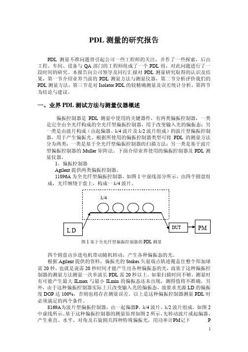
11896A为全光纤型偏振控制器,如图1中虚线部分所示,由四个圆盘组成,光纤缠绕于盘上,构成一λ/4波片。
图1基于全光纤型偏振控制器的PDL测量四个圆盘由步进电机带动随机转动,产生各种偏振态的光。
根据Agilent提供的资料,偏振光的Stokes矢量端点轨迹覆盖住整个邦加球需20秒,也就是说需20秒时间才能产生出各种偏振态的光,故基于这种偏振控制器的测量方法测量一次单波长PDL需20秒以上。
如果扫描时间不够,测量时有可能产生最大ILmax与最小ILmin的偏振态还未出现,测得值将不准确。
另外,由于这种偏振控制器实际上只改变输入光的偏振态,故要求光源LD的偏振度DOP达100%,否则也将存在测量误差。
以上是这种偏振控制器测量PDL时必须满足的两个条件。
8169A为波片型偏振控制器,由一起偏器P,λ/4波片,λ/2波片组成,如图2中虚线所示。
Agilent 81689A 81689B 81649A 可调光激光模块技术数据手册(2002年2月

Agilent 81689A / 81689B / 81649A Compact Tunable Laser ModulesTechnical SpecificationsFebruary 2002The 81689A, 81689B, 81649A compact tunable lasermodules offer superior performance now also in the compact module class. As they are tunable with continuous output power, they are the most flexible stimulus for the test of optical amplifiers, DWDM components as well as for the testof complete DWDM systems.1981Compact tunable lasers for C-and L-bandThe Agilent 81689A and 81689B modules operate in the C-band from 1525 nm to 1575 nm, whereas the Agilent 81649A covers the L-band from 1570 nm to 1620 nm.Test of optical amplifiersA variable amount of the compact, yet fully remote controlled Agilent 81689A, 81689B and 81649A tunable laser modules, in combination with the 81682A and 81642A high power Tunable Laser, is the ideal solution to characterize optical amplifiers for use in DWDM applications. The 81689A, 81689B and 81649A compact tunable laser modules provide the high stimulus power needed to test today's optical amplifiers. Together with the 81651A optical attenuator module, an output power dynamic range of more than60 dB can be achieved. Even without the attenuator module the power can be attenuated by 9dB (10dB for 81689B) e.g. to equalize power levels of several sources. Polarization Maintaining Fiber for the test of integrated optical devicesThe 81689A, 81689B and 81649A modules are ideally constructed to characterize integrated optical devices. Their optional Panda PMF output ports provide a well defined state of polarization to ensure constant measurement conditions on waveguidedevices. A PMF cable easily connectsan external optical modulator.The 81689A, 81689B and 81649A isavailable with both, standard single-mode fiber and Panda type PMF.Compact module for DWDMmulti-channel testThe 81689A, 81689B and 81489Aallow a realistic multi-channel test bedfor DWDM transmission systems to beset up.Their flexibility make them thepreferred choice for tests of DWDMtransmission system during installationand maintenance phases.Compact spare for DFBmodules in ITU gridsThe 81689B for the first time solvesthe sparing nightmare for users ofDWDM combs. In combination with acomb of 81662A DFB lasers the81689B can replace any DFB between1525nm and 1575nm without powerpenalty.Remote control & PnPsoftware drivers for easyprocess automationIts continuous, mode-hop free tuningmakes it quick and easy to set even themost complex configurations to thetarget wavelengths and power levels,just by dialing or using the vernier keys.A 8163B mainframe can host2 compact tunable laser modules. Thisallows for the most compact C- and L-band stimulus solution available today.Each 8164B mainframe can host up tofour units of the 81689A, 81689B or81649A in its upper slots.The 8166B is most interesting for highchannel count solutions. Up to17 compact tunable laser modules canbe hosted here.The 81649A, 81689A and 81689B areproduced to ISO 9001 internationalquality system standard as part ofAgilent's commitment to continuallyincreasing customer satisfactionthrough improved quality control.Specifications describe theinstrument's warranted performance.They are verified at the end of a 2 mlong patchcord and are valid afterwarm-up and for the stated outputpower and wavelength ranges.Each specification is assured bythoroughly analyzing all measurementuncertainties. Supplementaryperformance characteristics describethe instrument’s non-warranted typicalperformance.Every instrument is delivered with acommercial certificate of calibrationand a detailed test report.For further details on specifications,see the Definition of Terms in AppendixC of the Compact Tunable Laser User'sGuide.81689A, 81689B, 81649A Compact Tunable Laser for Multi-channel test applicationsAgilent 81689A Agilent 81689B Agilent 81649A Wavelength range1525 nm to 1575 nm1525 nm to 1575 nm1570 nm to 1620 nm Wavelength resolution0.01 nm, 1.25 GHz at 1550 nm0.01 nm, 1.25 GHz at 1550 nm0.01 nm, 1.17 GHz at 1595 nm Absolute wavelength accuracy (typ.) [1]±0.3 nm±0.3 nm±0.3 nmRelative wavelength accuracy [1]±0.3 nm±0.15 nm±0.15 nmWavelength repeatability [1]±0.05 nm±0.05 nm±0.05 nmWavelength stability(typ., over 24 h at constant temperature)[1] (typ., over 1 h at constant temperature)[1]±0.02 nm±0.01 nm±0.005 nm±0.01 nm±0.005 nmTuning speed (typ.)<10 sec/ 50 nm<10 sec/ 50 nm<10 sec/ 50 nmLinewidth (typ.) [2]with Coherence Control ON (typ.) [2]20 MHz---< 20MHz>100MHz< 20MHz>100MHzOutput power (continuous power on duringtuning)≥ 6 dBm (1525 –1575nm)≥ 10 dBm (1525 –1575nm)≥ 6 dBm (1570 –1620nm) Minimum output power–3 dBm0 dBm–3 dBmPower stability (at constant temperature) [3]±0.03 dB over 1 hour,typ. ±0.06 dB over 24 hours ±0.015 dB over 1 hour,typ. ±0.0075 dB over 1 hour,typ. ±0.05 dB over 24 hours±0.015 dB over 1 hour,typ. ±0.0075 dB over 1 hour,typ. ±0.05 dB over 24 hoursPower repeatability (typ.) [3]±0.02 dB±0.02 dB±0.02 dB Power linearity±0.1dB±0.1dB±0.1dB Power flatness versus wavelength±0.3 dB±0.2 dB±0.2 dBSide-mode suppression ratio (typ.) [2]> 40 dB(1525 – 1575 nm at 0 dBm)> 45 dB(1525 – 1575 nm at ≥ 3 dBm)> 45 dB(1570 – 1620 nm at ≥ 0 dBm)Signal to source spontaneous emission ratio (typ.) [4]≥ 39 dB/ nm(1525 –1575 nm at 6 dBm)≥ 44 dB/ nm(1525 –1575 nm at 10 dBm)≥ 42 dB/ nm(1570 – 1620 nm at 6 dBm)Relative intensity noise (RIN, typ.)< -137 dB/Hz(100 MHz – 2.5 GHz, at +3 dBm)< -137 dB/Hz(100 MHz – 2.5 GHz, at +7 dBm)< -137 dB/Hz(100 MHz – 2.5 GHz, at +3 dBm)Dimensions75 mm H, 32 mm W, 335 mm D(2.8" x 1.3" x 13.2")75 mm H, 32 mm W, 335 mm D(2.8" x 1.3" x 13.2")75 mm H, 32 mm W, 335 mm D(2.8" x 1.3" x 13.2")Weight 1 kg 1 kg 1 kg[1]At CW operation. Measured with wavelength meter based on wavelength in vacuum.[2]Measured by heterodyning method.[3]500 ms after changing power.[4]Measured with optical spectrum analyzer at 1 nm resolution bandwidth.Listed optionsOption 021: standard single mode fiber,straight contact output connectorOption 022: standard single mode fiber,angled contact output connectorOption 071: polarization maintainingfiber, straight contact output connectorOption 072: polarization maintainingfiber, angled contact output connectorSupplementary performance characteristics ModulationInternal digital modulation50% duty cycle, 200 Hz to 300 kHz.>45% duty cycle, 300 kHz to 1 MHz. Modulation output (via Mainframe): TTL reference signal.External digital modulation> 45% duty cycle, fall time< 300 ns, 200 Hz to 1 MHz. Modulation input (via Mainframe):TTL signal.External analog modulation≥ ±15% modulation depth,5 kHz to 1 MHz.Modulation input: 5 Vp-p Coherence control(81649A/81689B)For measurements on components with 2 m long patchcords and connectors with 14 dB return loss, the effective linewidth results in a typical power stability of< ±0.025 dB over1 minute by reducing interference effects in the test setup.GeneralOutput isolation (typ.):38 dBReturn loss (typ.):55 dB (options 022, 072)40 dB (options 021, 071)Polarization maintaining fiber (Options071, 072)Fiber type: Panda.Orientation: TE mode in slow axis,in line with connector key.Extinction ratio: 16 dB typ.Laser class:Class IIIb according to FDA 21 CFR1040.10, Class 3A according to IEC 825- 1; 1993.Recommended re-calibration period:2 years.Warm-up time:< 40 min,immediate operation after boot-up.EnvironmentalStorage temperature:–20 °C to +70 °C (81689A)–40 °C to +70 °C (81689B, 81649A)Operating temperature:15 °C to 35 °CHumidity:< 80 % R.H. at 15 °C to 35 °CSpecifications are valid in non-condensingconditions.Laser Safety InformationAll laser sources specified by this datasheet are classified as Class 1Maccording to IEC 60825-1 (2001).All laser sources comply with 21 CFR1040.10 except for deviations pursuantto Laser Notice No. 50, dated 2001-July-26This page intentially left blankAgilent Technologies’Test and Measurement Support,Services, and AssistanceAgilent Technologies aims to maximize the value you receive, while minimizing your risk and problems. We strive to ensure that you get the test and measurement capabilities you paid for and obtain the support you need. Our extensive support resources and services can help you choose the right Agilent products for your applications and apply them successfully. Every instrument and system we sell has a global warranty. Support is available for at least five years beyond the production life of the product. Two concepts underlie Agilent's overall support policy: "Our Promise" and "Your Advantage."Our PromiseOur Promise means your Agilent test and measurement equipment will meet its advertised performance and functionality. When you are choosing new equipment, we will help you with product information, including realistic performance specifications and practical recommendations from experienced test engineers. When you use Agilent equipment, we can verify that it works properly, help with product operation, and provide basic measurement assistance for the use of specified capabilities, at no extra cost upon request. Many self-help tools are available.Your AdvantageYour Advantage means that Agilent offers a wide range of additional expert test and measurement services, which you can purchase according to your unique technical and business needs. Solve problems efficiently and gain a competitive edge by contracting with us for calibration, extra-cost upgrades, out-of-warranty repairs, and on-site education and training, as well as design, system integration, project management, and other professional engineering services. Experienced Agilent engineers and technicians worldwide can help you maximize your productivity, optimize the return on investment of your Agilent instruments and systems, and obtain dependable measurement accuracy for the life of those products.By internet, phone, or fax, get assistance with all your test & measurement needsOnline assistance:Related Agilent Literature:/coms/lightwaveAgilent 8163A Lightwave MultimeterPhone or Fax Agilent 8164A Lightwave Measurement SystemUnited States:Agilent 8166A Lightwave Multichannel System(tel)180****4844Technical Specificationsp/n 5988-1568ENCanada:(tel)187****4414Agilent 81662A DFB Laser(fax) (905) 206 4120Agilent 81663A DFB LaserAgilent Fabry Perot LaserTechnical SpecificationsEurope:p/n 5988-1570EN(tel) (31 20) 547 2323(fax) (31 20) 547 2390Agilent Power Sensor ModulesJapan:Agilent Optical Heads(tel) (81) 426 56 7832Agilent Return Loss Modules(fax) (81) 426 56 7840Technical Specificationsp/n 5988-1569ENLatin America:(tel) (305) 269 7500(fax) (305) 269 7599Agilent 8163A/B Lightwave MultimeterAgilent 8164A/B Lightwave Measurement SystemAustralia:Agilent 8166A/B Lightwave Multichannel System(tel) 1 800 629 485 Configuration Guide(fax) (61 3) 9210 5947p/n 5988-1571ENNew Zealand:Agilent 8163B Lightwave Multimeter(tel) 0 800 738 378Agilent 8164B Lightwave Measurement System(fax) 64 4 495 8950Agilent 8166B Lightwave Multichannel SystemTechnical SpecificationsAsia Pacific:p/n 5988-3924EN(tel) (852) 3197 7777(fax) (852) 2506 9284Product specifications and descriptions in this document subject to change without notice.Copyright © 2001 Agilent TechnologiesFebruary 12 20025988-3675EN。
欧里森SPECTRACOM模型8165脉冲振荡器WWVB时间戳接收器说明书
LBI-33059 SPECTRACOM MODEL 8165 DISCIPLINED OSCILLATORANTENNA INSTALLATIONThis manual supplements information in the Spectracom Model 8165 WWVB Disciplined Oscillator Instruction Manual, Revision 2.2.The section numbers in this document correspond to those in the original document.1.0INTRODUCTIONThe Spectracom Model 8165 WWVB Disciplined Oscillator™ is a frequency standard with accuracy directly traceable to the National Institute of Standards and Technology. The Spectracom Model 8206A Loop Antenna or Model 8208 Whip Antenna (see Figure 1-5) receives the 60-kHz carrier of WWVB. The WWVB/8165 receiver is very important to the performance of an Ericsson EDACS Simulcast or Multisite system.The Model 8165 is continuously monitored against WWVB and kept on frequency by a microprocessor. The oscillator outputs can be used as a precise reference input for transmitters, receivers, counters, synthesizers, and other electronic equipment.1.3MODEL 8206A LOOP ANTENNAThe Model 8206A Loop Antenna reliably receives the 60-kHz WWVB transmission in field strengths of 50µV/meter or greater. The majority of the United States exceeds 50 µV/meter as shown in Figure 1-2, Measured Field Intensity Contours. In locations having less than 50µV/meter field strength, the Model 8207 Preamplifier is required. The equivalent electrical height of the Model 8206A is 5.0 cm. Refer to Section 1.7 of the Model 8165 manual for additional information.The Model 8206A consists of a wound ferrite core surrounded by a Faraday shield which aids in noise rejection. The received signal is amplified by an internal preamplifier and output to the receiver. The preamp is powered by the receiver over the antenna coax. The antenna is packaged in a PVC housing measuring 10 inches long and 2.8 inches in diameter. The assembled antenna weighs 2.5 pounds.Use the great circle map shown as Figure 1-3 in the Model 8165 manual to determine the correct antenna orientation per receiver location. The antenna position may be optimized using the AGC measurement described in Section 2.4 of the Model 8165 manual.The tubular housing of the Model 82060A antenna must be positioned broadside to Fort Collins, Colorado, (See Figure 1-4 great circle map) and horizontal to the ground to allow maximum signal reception. No signal will be received if the tube points directly toward the transmitter site, as the antenna pattern nulls are located off the ends of the tube.Correct orientation of the WWVB/8165 antenna is very important to the performance of an Ericsson EDACS Simulcast or Multisite system.FIGURE 1-2 MEASURED FIELD INTENSITY CONTOUR WWVB @ 13 kW ERPFIGURE 1-3 MODEL 8206A DIRECTIONAL ANTENNAWWVBFt Collins, COFIGURE 1-4 GREAT CIRCLE MAP CENTERED ON FORT COLLINS, COLORADOFIGURE 1-5 MODEL 8208 WHIP ANTENNA1.4MODEL 8208 WHIP ANTENNAThe Model 8208 Whip Antenna shown in Figure 1-5provides performance equal to the Model 8206A Loop Antenna at a reduced cost. The Model 8208 may be used in field strengths of 50 µV/meter or greater. The Model 8208contains a preamplifier housed in a weather-proof enclosure. The preamplifier is powered by the receiver over the antenna coaxial cable. Model 8208 is 58.5 inches long and weighs 1.3 pounds.1.5ANTENNA LOCATIONThe antenna should be mounteda minimum of 25 feet from the receiver to prevent regeneration. The antenna MUST NOT be positioned next to the receiver or on top of it . Doing so will cause the results obtained with the equipment to be meaningless even though the green lock lamp on the receiver front panel may be illuminated.In system installations where more than one Spectracom antenna is used, a minimum separation of 10 feet between antennas is recommended (see photo 2).The antenna must be at least 3 feet from any steel beams, roof decking, pipes, etc. (see Photo 1 and the text beneath it) because metal will detune the antenna and cancause as much as 20 dB degradation of the signal-to-noise ratio.The antenna must NOT be mounted under a metal roof or inside a building with heavy steel structural supports because these shield the antenna from the signal. Rooftops are generally acceptable if a clear path toward Fort Collins is available without being blocked by a large steel structure .Attics are ideal sites if the roof and rafters are not metallic. The signal-to-noise ratio will be optimized if the antenna is located as far as possible from local RF noise sources such as TV sets, or fluorescent or neon lamps that blink or sputter on and off. Any equipment containing a switching power supply is a probable cause of interference.1.6ANTENNA INSTALLATIONMount the antenna where it will not be disturbed.Antenna height is not critical because the 60-kHz signal is primarily a ground wave. Positioning the antenna 2 to 3 feet off the ground or rooftop is adequate. Each antenna includes a 2-foot mast assembly and two hose clamps to simplify installation. The antenna SHOULD NOT BE MOUNTED near or under steel ice-bridges as shown in Photos 1 and 2 on the next page.PHOTO 1PHOTO 2The 8165 antenna(s) should be clear of any metal objects. Install the loop and/or whip antenna(s) at least 3feet from any metal objects. When more than one Model 8165 is employed, space the associated antenna(s) at least10 feet apart. The arrows in Photo 2 indicate insufficient spacing between the two antennas (measured 7 ft), (see text).Spectracom offers an aluminum base (Model 8213) for installations where vent pipe mounting is not practical or desired.Spectracom recommends RG-58C/U coax for the antenna cable, though any 50-ohm coax with superior specifications may be used. The antenna coax is used to provide the antenna with its DC operating voltage and the receiver with the amplified WWVB signal. Because of low attenuation characteristics at 60 kHz and the very low power requirement of the antenna (10 mW), cable lengths up to 1,500 feet are possible if care is taken to avoid paralleling noise sources.1.7MODEL 8207 PREAMPLIFIERINSTALLATIONThe Spectracom Model 8207 Preamplifier is a low noise, tuned, 60-kHz line amplifier used in the antenna feed line wherever the WWVB signal strength is less than 50µV/meter at the Model 8206 Loop Antenna or less than 0.4µV at the receiver antenna terminal. Typical locations where the preamplifier is required are Hawaii, Alaska,Puerto Rico, and the Canal Zone. Figure 1-2 shows the measured average signal strength for the contiguous 48states. Atmospheric conditions may cause short-term degradation of field intensity. The Model 8207 Preamplifier provides approximately 40 dB of gain between the antenna and receiver, increasing sensitivity to 4.0 nanovolts.The preamplifier is connected in the antenna feed line with INPUT connected to the antenna and OUTPUT connected to the receiver. Because of the high gain of the system, it is recommended that the preamplifier be located at least 10 feet away from the receiver. The antenna must be least 25 feet beyond the preamplifier. Switch A1S1 of the receiver RF Amplifier must be set at its right-hand position,marked PREAMP or P, prior to equipment turn-on, to apply DC voltage to the Model 8207 on the antenna feed line.If the preamplifier is removed from the system, the switch must be placed in the left-hand position, marked ANT or A prior to turn-on.Ericsson Inc. Private Radio Systems Mountain View Road Lynchburg, Virginia。
testo 815、816 声音级别计量仪说明书

815815815testo 815 / 816Whether at a working place , in machine halls, offices, in discotheques or in the environmental field, it is important to control sound levels, which is often prescribed. testo 815 and 816 are easy to operate, precise sound level measuring instruments of the accuracy class 2. A calibrator for controlling and calibrating can be ordered as an accessory.Next to the human eye the human ear is the sense organ used the most. Due to sound occurences in our ambience - be it a tone, music, bird twittering or machine noise - we participate in our ambience via the ears. The ears are a precious sense organ, which is necessary to be protected. Especially in the job-related everyday life, sound is generated by machine noise in a way we sense as disturbing. Everybody knows, noise and sound occurences, which are too loud on a continuing basis can damage the ear permanently. The new sound level measuring instruments testo 815 / 816 are modern sound level measuring instruments, which allow us to measure and evaluate sound, noise or pure tones.The Parameter SoundThe instrument for evaluators, workplace measurements and measuring industrial and environmental noise. The bigger model offers additional features compared to the testo 815, which predestine it especially for evaluators,workplace measurements and measuring industrial and environmental noise.testo 816Real-world Sound Level Measuring Instruments•Automatic range switchover •Backlit display •Mains unit connection •BarGraph display•AC output to connection from recorders and amplifiers•DC output with 10 mV/dB to connect recorders or dataloggersAdditional benefits of testo 816:threshold of painstart of yet planestrucksofficelibraryforesthearing limitjack hammerfrequency weighting A/C automatic range switchovertime weighting part of meas. range frequency weighting present readingMax / Min memoryOn /Off keytime weighting Fast / Slow backlit display On / Offanalog output AC/DC mains unit connectioneasy calibration with screwdriverSound level measuring instruments should be re-calibrated in case of changes in place or temperature. With the help of the calibrator, available as an accessory, both instruments can easily be controlled and adjusted. Two levels can be adjusted (94 and 114 dB). It is as well suited for 1/2 inch and 1 inch microphones of other makes.The ideal instrument for daily use. Whether it is for air conditioning or heating, disco noise, machine noise or noise in combustion systems, testo 815 is the ideal partner.testo 815•Accuracy class 2 according to IEC 60651•Easy to adjust (calibration screwdriver included)•Frequency weighting according to characteristic line A and C •Max / Min memory•Built-in stand screw /(1/4 inch)•Switchable time weighting Fast / SlowSound Level CalibratorFor regular control, especially in case of temperature or air pressure variations, due to changing weather conditions, the measuring instrument should be adjusted with a calibrator. 2 levels can be adjusted at the calibrator (94 dB / 114 dB).Sound level calibrator, more security!2 levels adjustableMutual features of both instrumentsSound weighted curves•The “A” weighted graph corresponds to the hearing sensation of the human ear.•The “C” weighted graph is used for measuring low frequency sounds.LED function and batterystatus indication Removable adapter ring for calibrating instruments with 1 inch microphones. With inserted adapter ring 1/2 inch microphones can be fitted (testo 815 / 816).frequency (Hz)LA (dB)Max / Min memoryfrequency weighting A/C On / Off key time weighting Fast / Slowautomatic range switchoverfrequency weighting present readingtime weightingpart of measuring rangeeasy calibration with a screwdriverSenderName Company Department Address CityDate, SignatureS u b j e c t t o c h a n g e w i t h o u t n o t i c e .Technical data testo 815+32 to +130 dB Meas. range Resolution Oper. temp.Storage temp.Battery life Weight Section measurement ranges: 30 to 80 dB; 50 to 100 dB; 80 to 130 dB Time weighting: FAST 125 ms setting / SLOW 1 s settingPressure dependency: -0.0016 dB/hPaOther featuresAccuracy±1 digittesto 816+30 to +130 dB Class 2±1.0 dB Class 2±1.0 dB 0.1 dB 0.1 dB 70 h 50 h 195 g0 to +40 °C 9V block battery -10 to +60 °C0 to +40 °C 9V block battery -10 to +60 °C315 gDimensions 255x 55x 43mm 309x 68x 50mm Battery type Battery type 9V block battery Technical dataSound level calibrator 40 hBattery life ±0.5 dB in accordance with Class 2to IEC 60942AccuracySound pressure level: 94 dB/114 dB, switchable Frequency: 1000 HzAlso suitable for 1/2 and 1 inch microphones by other manufacturers<c m s a t t r A ="983" O ="34703"815815815。
Agilent N2795A 96A 97A单端活动探头数据手册说明书

N2795A/96A/97A Single-ended Active ProbesData SheetKey Features• High resistance (1MΩ) and low capacitance (1 pF) input for low loading• Wide input dynamic range (±8V) and offset range (±12V for N2796A/97A, ±8V for N2795A)• Built-in headlight for better visibility while probing • Includes various probe tip accessories• Direct connection to AutoProbe interface (no power supply required)• Provides full system bandwidth with InfiniiVision and Infiniium oscilloscopes with bandwidths up to 1 GHz• N2797A for extreme temperature environmentalchamber testing at –40 to +85 °CThe N2795A/96A are low-cost, 1 and 2 GHz single-ended active probes with the AutoProbe interface (compatible with Agilent’s InfiniVision and Infiniium family of oscilloscopes). These probes integrate many of the characteristics needed for today’s general-purpose, high-speed probing - especially in digital system design, component design/characteriza-tion, and educational research applications. Its 1MΩ input resistance and extremely low input capacitance (1 pF) provide ultra low loading of the DUT. This, accompanied with superior signal fidelity, makes these probes useful for most of today’s digital logic voltages. And with their wide dynamic range(±8 V) and offset range (±12 V for N2796A/97A, ±8 V forN2795A), these probes can be used in a wide variety of applications.For high signal integrity probing, the N2795A 1 GHz andN2796A 2 GHz active probes are perfect complements to Agilent’s 500 MHz – 600 MHz and 1 GHz bandwidth scopes, respectively. The N2796A 2 GHz probe can also be used with Agilent’s 2 GHz or higher bandwidth Infiniium scope as a low cost alternative to InfiniiMax probes.Testing devices over extreme temperature ranges is quite common these days. The N2797A single-ended active probe is the industry’s first low-cost high input impedance active probe with rugged probe tips for environmental chamber test-ing of ICs and devices. The probe gives the ability to probe signals at drastic temperature swings ranging from –40 to +85 °C. The probe provides 1.5 GHz of bandwidth and a 2 m long cable.The N2795A/96A/97A are equipped with a pleasant white LED headlight to illuminate the circuit under test. The probes are powered directly by the InfiniiVision and Infiniium Autoprobe interface, eliminating the need for an additional power supply. The probes also come with a number of accessories that allow for easy connections to the circuit under test.N2795A/96A active probewith standard accessoriesA White LED headlight can be turned on to illuminatethe circuit under test for better visibility while probingN2797A with standardaccessoriesN2795AN2796AN2797AProbe bandwidth* (–3 db) 1 GHz 2 GHz 1.5 GHz**Risetime (calculated, 10-90%)350 psec 175 psec 233 psec System bandwidth (with Agilent oscilloscope)500/600 MHz (with Agilent’s 500/600 MHz InfiniiVision/ Infiniium oscilloscope)1 GHz (with Agilent’s 1 GHz InfiniiVision/Infiniium oscilloscope) 1 GHz (with Agilent’s 1 GHz InfiniiVision/Infiniium oscilloscope)Attenuation ratio (@DC)10:1 ± 0.5%Input dynamic range–8 V to +8 V (DC or peak AC)Non-destructive max input voltage –20 V to +20 VOffset range ±8 V±12 V ±12 VDC offset error (Output zero)< ±1 mVFlatness (at 25 °C)Typical 0.4 dB(100 kHz - 100 MHz) Typical 0.6 dB(100 MHz - 500 MHz) Typical 0.8 dB (500 MHz - 1 GHz) Typical 1.3 dB (1 GHz - 2 GHz)Typical 0.3 dB (10 Hz – 100 MHz) Typical 0.8 dB (100 MHz – 1 GHz) Typical 2.0 dB (1 GHz – 1.5 GHz)Flatness over temperature (–40 to +85 °C)Typical 0.3 dB (10 Hz – 100 kHz) Typical 0.6 dB(100 kHz – 100 MHz) Typical 0.8 dB(100 MHz – 500 MHz) Typical 2.0 dB (500 MHz – 1 GHz) Typical 2.5 dB (1 GHz – 1.5 GHz)Input resistance* 1 MΩ +0 %, –2.5 %1 MΩ ±3%Inputcapacitance 1 pFProbe noise < 2.5 mVrms (referred to input)Output impedance50 ΩN2795AN2796A N2797AInternal power Agilent Autoprobe Interface from scope(InfiniiVision and Infiniium)Cable length 1.3 m 2 m Probe weight Approx. 100 g Approx. 108 g Ambient operating Temperature 0 to 50 °C –40 to +85 °C Ambientnon-operating temperature –40 to 70 °C–40 to +85 °COperating humidity95% RH @ 40 °C Non-operating humidity 90% RH @ 65 °COperating altitude 4000 mESD8 kV HBM Standard accessories- 2 each spring probe tip - 2 rigid probe tip- 1 each flex nose clip adapter (red and black)- 1 each copper pad, 10x - 1 each Y -lead adapter, 10 cm - 1 each right angle ground, 5 cm - 1 each right angle ground, 10 cm - 2 each ground blade - 1 each offset ground - 1 each flex ground- 4 color coded rings (each yellow, green, blue and purple)- 10 each solderable tip - 5 each rigid probe tip - 2 each flex nose clip adapter (red and black) - 1 each pico hook tip (red and black)- 2 each Y-lead adapter, 9 cm (800 MHz)- 2 each Y-lead adapter, 6 cm (1 GHz)- 2 each right angle ground, 5 cm- 2 each ground blade - 4 color coded rings (each yellow, green, blue and purple)Others (included)-1 each accessory configuration card Compatible Agilent scopes Agilent InfiniiVision 3000 X-, 4000 X-, 5000, 6000, 7000 (except 6000 100MHz) and Infiniium 9000, 90000, 90000 X-Series (with N5442A)Agilent InfiniiVision 3000 X-, 4000 X- andInfiniium 9000, 90000 and 90000 X-/Q-Series (with N5442A)* denotes warranted electrical specifications after 20 minute warm-up, all others are typical ** typical 2 GHz, when used with rigid probe tip, ground blade and handheldUse flex nose clip adapters with the dual lead adapter to obtainaccess to IC leads or head connectors.The dual lead adapter allows you to easily connect the probe to a popular 0.1” pin header with 0.025” square pins.Model numberDescriptionN2795A 1 GHz single-ended active probe N2796A 2 GHz single-ended active probeN2797A 1.5 GHz extreme temperature single-ended active probeN2798AAccessory kit for N2797ACharacteristics100.0 k 10.00 k 1.000 k 100.0Frequency (Hz)Impedance(Ohms)Frequency response of N2796A (Vout/Vin)Time domain step response of N2796A (with Agilent MSO9404A) Voltage derating over frequency (N2796A)Input impedance over frequency (Red = measured, Blue = model) Measurement PlotsN2797A measuring a step signal over –40 to +90 °C, oscilloscopein infinite persistence mode/find/N2795AFor more information on AgilentTechnologies’ products, applications or services, please contact your local Agilent office. The complete list is available at:/find/contactus Americas Canada (877) 894 4414 Brazil (11) 4197 3600Mexico 01800 5064 800 United States (800) 829 4444 Asia Pacific Australia 1 800 629 485China 800 810 0189Hong Kong 800 938 693India 1 800 112 929Japan 0120 (421) 345Korea 080 769 0800Malaysia 1 800 888 848Singapore 180****8100Taiwan 0800 047 866Other AP Countries (65) 375 8100 Europe & Middle East Belgium 32 (0) 2 404 93 40 Denmark 45 45 80 12 15Finland 358 (0) 10 855 2100France 0825 010 700* *0.125 €/minute Germany 49 (0) 7031 464 6333 Ireland 1890 924 204Israel 972-3-9288-504/544Italy 39 02 92 60 8484Netherlands 31 (0) 20 547 2111Spain 34 (91) 631 3300Sweden 0200-88 22 55United Kingdom 44 (0) 118 927 6201For other unlisted countries:/find/contactus(BP-3-1-13)Product specifications and descriptions in this document subject to change without notice.© Agilent Technologies, Inc. 2010, 2013Printed in USA, August 17, 20135990-6480ENLAN eXtensions for Instruments puts the power of Ethernet and the Web inside your test systems. Agilent is a founding member of the LXI consortium.Agilent Channel Partners/find/channelpartners Get the best of both worlds: Agilent’s measurement expertise and product breadth, combined with channel partner convenience./qualityAdvancedTCA ® Extensions forInstrumentation and Test (AXIe) is an open standard that extends theAdvancedTCA for general purpose and semiconductor test. Agilent is a founding member of the AXIe consortium.PCI eXtensions for Instrumentation (PXI) modular instrumentation delivers a rugged, PC-based high-performance measurement and automation system.Quality Management SystemQuality Management Sys ISO 9001:2008DEKRA Certified /find/myagilentA personalized view into the information most relevant to you.myAgilentmy /find/AdvantageServices Accurate measurements throughout the life of your instruments./find/ThreeYearWarranty Agilent’s combination of product reliability and three-year warranty coverage is another way we help you achieve your business goals: increased confidence in uptime, reduced cost of ownership and greater convenience.。
Agilent 8156A高性能光谱调节器配置指南说明书

1981Agilent 8156AOptical AttenuatorConfiguration GuideThe Agilent 8156A is a high performance optical attenuator for single andmultimode optical fiber transmission systems. It is available in variousconfigurations for best possible match to the most common applications.This configuration guide describes the options available and how theyshould be ordered. Options cannot be used without the mainframe Agilent8156A and two or three connector interfaces, such as the Agilent 81000FI.The Agilent 8156A is produced to the ISO 9001 international qualitysystem standard as part of Agilent´s commitment to continually increasingcustomer satisfaction through improved quality control.Back Reflector Setup for Option 100,101,121Agilent 8156AAgilent 81000AIConnector InterfaceDiamond HMS-10Agilent 81000BRReferenceReflector Output PortBack Reflector Setup for Option 201,221Agilent 8156A Output PortAgilent 81000SIConnectorInterfaceDIN 4108Agilent 81113PCPathcordAgilent 81000FIConnectorInterfaceFC/PC/SPC/APCAgilent 81000UMUniversalTroughAdapterAgilent 81000BRReferenceMonitorOption 203 Back reflector Kit2Agilent 8156A:Non-modular mainframe for opticalattenuatorOption 100:Standard performance version with 35dBreturn loss and straight contactconnectors; two connector interfacesrequiredOption 101:High performance version with 45dBreturn loss and straight contactconnectors; two connector interfacesrequired.Option 201:High performance version with 60dBreturn loss and angled contactconnectors; two connector interfacesrequired.Option 121:High performance version with 45dBreturn loss and straight contactconnectors built-in monitor output (13dBtap), three connector interfaces requiredOption 221:High performance version with 60dBreturn loss and angled contact connectorsbuilt-in monitor output (13dB tap), threeconnector interfaces requiredOption 350:Standard performence version for50/125 µm multimode fibers; twoconector interfaces required3Agilent Technologies’ Test and Measurement Support, Services, and AssistanceAgilent Technologies aims to maximize the value you receive, while minimizing your risk and problems. We strive to ensure that you get the test and measurement capabilities you paid for and obtain the support you need. Our extensive support resources and services can help you choose the right Agilent products for your applications and apply them successfully. Every instrument and system we sell has a global warranty. Support is available for at least five years beyond the production life of the product. Two concepts underlie Agilent's overall support policy: "Our Promise" and "Your Advantage."Our PromiseOur Promise means your Agilent test and measurement equipment will meet its advertised performance and functionality. When you are choosing new equipment, we will help you with product information, including realistic performance specifications and practical recommendations from experienced test engineers. When you use Agilent equipment, we can verify that it works properly, help with product operation, and provide basic measurement assistance for the use of specified capabilities, at no extra cost upon request. Many self-help tools are available.Your AdvantageYour Advantage means that Agilent offers a wide range of additional expert test and measurement services, which you can purchase according to your unique technical and business needs. Solve problems efficiently and gain a competitive edge by contracting with us for calibration, extra-cost upgrades, out-of-warranty repairs, and on-site education and training, as well as design, system integration, project management, and other professional engineering services. Experienced Agilent engineers and technicians worldwide can help you maximize your productivity, optimize the return on investment of your Agilent instruments and systems, and obtain dependable measurement accuracy for the life of those products.By internet, phone, or fax, get assistance with all your test & measurement needsOnline assistance:/comms/lightwavePhone or FaxUnited States:(tel)180****4844Canada:(tel)187****4414(fax) (905) 282-6495Europe:(tel) (31 20) 547 2323(fax) (31 20) 547 2390Japan:(tel) (81) 426 56 7832(fax) (81) 426 56 7840Latin America:(tel) (305) 269 7500(fax) (305) 269 7599Australia:(tel) 1 800 629 485(fax) (61 3) 9210 5947New Zealand:(tel) 0 800 738 378(fax) 64 4 495 8950Asia Pacific:(tel) (852) 3197 7777(fax) (852) 2506 9284Product specifications and descriptions in this document subject to change without notice. Copyright c 2000 Agilent TechnologiesNovember 05 20015963-3367E Related Agilent Literature Agilent 8156AOptical Attenuator Technical SpecificationsP/n 5962-8631E。
Agilent 816x系列主机和模块配置指南说明书
Agilent 8163A/B Lightwave Multimeter Agilent 8164A/B Lightwave Measurement System Agilent 8166A/B Lightwave Multichannel System Configuration GuideFebruary 2002_1This guide provides configuration details for the Agilent816x family of mainframes and modules, includingoptions and accessories.Power Sensor Modules Page 781630B 81634B 81635AFast Power Sensor Modules Page 781636B 81637B8164A/B Lightwave Measurement System81613A - 1310/1550nm 81614A - 1550/1625nm2Information about Agilent connectors and connector interfaces can be found at /comms/oct-accessories81480A, 81680A, 81640A81642B,81682A, 81642ATunable Laser SourcesLow SSE Modules81480B - 1400nm 81680B - 1550nm 81640B - 1600nm 81480A - 1400nm 81680A - 1550nm 81640A - 1600nmFor Laser Safety see page 12High-Performance Tunable Laser ModulesSpecifiy 81645A Filler Module if no highperformance tunable laser is installedNote: Option 072 is highly recommended over Option 071 to reduce front-panel connector reflections which will greatly reduce interference noise and spectral ripple in the test setup.381000AI 81000FI 81000GI 81000HI 81000KI 81000SI 81000VI 81000WIDiamond HMS-10FC/PC/SPC D4E-2000SC/PC/SPC DIN 47256ST BiconicCompact Tunable Laser ModuleFor Laser Safety see page 12will greatly reduce interference noise and spectral ripple in the test setup.4DFB Source Modules5For Laser Safety see page 12SourceSourceFP Standard SourceModules0 dBm6Power Sensor ModulesPower Sensors Economy Modules81632A/B +10 dBm to –80 dBm (single channel)81635A +10 dBm to –80 dBm (dual channel)81636B + 10 dBm to –80 dBm (Fast Power Sensor)Connector Interfaces81000AI Diamond HMS-1081000FI FC/PC/SPC 81000GI D481000JI SMA81000KI SC/PC/APC 81000PI E-200081000SI DIN 47256 / 4108.681000VI ST 81002LI LCPower SensorsHigh Performance Modules 81633A/B +10 dBm to –90 dBm 81634A/B +10 dBm to –110 dBm81637B + 10 dBm to –80 dBm (Fast Power Sensor)81630B +28 dBm to –70 dBm 81000BB Bare Fiber Kitfits into connector interfaces:81000AI Diamond HMS-1081000FI FC/PC/SPC 81000KI SC81000SI DIN 47256 / 4108.681000VI ST 81000PIE-2000Following singleCombination is available 81000FI FC81000FB Bare Fiber AdapterNote: All sensor inputs are non-contact and accept both straight and angled connectors.(bare fiber)Connector InterfacesConnector InterfacesSensor Module Interface for both angled and straight connectorsBare Fiber Adapter7Optical Heads (5mm Sensor)Optical Heads(3mm Sensor)InterfaceNA ≤ 0.11 (Single mode fiber)NA ≤ 0.22 (Multi mode fiber)9Return Loss ModulesConnector Interfaces for angled contacts 81000SI DIN 4108.681610CC Reference Cable – for calibration of all 8161xA Return Loss ModulesConnectors - DIN 4108.6 (connectors to modules) and FC/PC supplied (w/calibrated return loss values)An 81000SI connector interface is required to connect this cable to the module.This cable is used for calibration only, not for measurements.Reference CableDIN 4108.6FC/PC10For Laser Safety see page 12Optical Attenuator Modules81561AOptical Attenuator (single slot)81567AOptical Attenuator with Power Control (dual slot)Connector Interfaces 81000 HI E-2000 APC 81000 KI SC/APC 81000 NI FC/APC 81000 SI DIN 4108.681560AOptical Attenuator (single slot)81566AOptical Attenuator with Power Control (dual slot)Connector Interfaces 81000 AI HMS-1081000 FI FC/PC/SPC 81000 GI D481000 HI E-200081000 KI SC/PC/SPC 81000 SI DIN 4725681000 VI ST11Laser Safety Information81611A 1310nm RL81612A 1550 nm RL81613 1310/1550nm RL81614 1550/1625nm RL81650A 1310 nm FP81651A 1550 nm FP81652A 1550/1625 nm FP81654A 1310/1550 nm FPThe laser sources listed directly above are classified as Class 1 according to IEC 60825-1 (2001).All laser sources comply with 21 CFR 1040.10 except for deviations pursuant to Laser Notice No. 50, dated 2001-July-26.CLASS 1 LASER PRODUCT(IEC 60825-1 / 2001)81655A 1310nm FP81656A 1550 nm FP81657A 1310/1550 nm FP81662A C- and L-Band DFB81663A C-band DFB81480B 1400nm TLS81680B 1550nm TLS81640B 1600nm TLS81672B 1300nm TLS81482B 1400nm TLS81682B 1550nm TLS81642B 1600nm TLS81480A 1400nm TLS81640A 1600nm TLS81642A 1600nm TLS81680A 1550nm TLS81682A 1550nm TLS81689A 1550nm TLS81689B 1550nm TLS81649A 1595nm TLSThe laser sources directly listed above are classified as Class 1M according to IEC 60825-1 (2001).All laser sources comply with 21 CFR 1040.10 except for deviationspursuant to Laser Notice No. 50, dated 2001-July-26.Further information about Agilent connectors and connector interfaces can be found at /comms/oct-accessories 12This page intentionally left blankAgilent Technologies’Test and MeasurementSupport, Services, and AssistanceAgilent Technologies aims to maximize the value you receive, while minimizing your risk and problems. We strive to ensure that you get the test and measurement capabilities you paid for and obtain the support you need. Our extensive support resources and services can help you choose the right Agilent products for your applications and apply them successfully. Every instrument and system we sell has a global warranty. Support is available for at least five years beyond the production life of the product. Two concepts underlie Agilent's overall support policy: "Our Promise" and "Your Advantage."Our PromiseOur Promise means your Agilent test and measurement equipment will meet its advertised performance and functionality. When you are choosing new equipment, we will help you with product information, including realistic performance specifications and practical recommendations from experienced test engineers. When you use Agilent equipment, we can verify that it works properly, help with product operation, and provide basic measurement assistance for the use of specified capabilities, at no extra cost upon request. Many self-help tools are available.Your AdvantageYour Advantage means that Agilent offers a wide range of additional expert test and measurement services, which you can purchase according to your unique technical and business needs. Solve problems efficiently and gain a competitive edge by contracting with us for calibration, extra-cost upgrades, out-of-warranty repairs, and on-site education and training, as well as design, system integration, project management, and other professional engineering services. Experienced Agilent engineers and technicians worldwide can help you maximize your productivity, optimize the return on investment of your Agilent instruments and systems, and obtain dependable measurement accuracy for the life of those products.By internet, phone, or fax, get assistance with all your test & measurement needsOnline assistance:/comms/lightwavePhone or FaxUnited States:(tel)180****4844Canada:(tel)187****4414(fax) (905) 206 4120Europe:(tel) (31 20) 547 2323(fax) (31 20) 547 2390Japan:(tel) (81) 426 56 7832(fax) (81) 426 56 7840Latin America:(tel) (305) 269 7500(fax) (305) 269 7599Australia:(fax) (61 3) 9210 5947New Zealand:(tel) 0 800 738 378(fax) 64 4 495 8950Asia Pacific:(tel) (852) 3197 7777(fax) (852) 2506 9284Product specifications and descriptions in this document subject to change without notice. Copyright © 2002 Agilent TechnologiesFebruary, 12 20025988-1571EN Related Literature:Agilent 8163B Lightwave MultimeterAgilent 8164B Lightwave Measurement SystemAgilent 8166B Lightwave Multichannel SystemTechnical Specificationsp/n 5988-3924ENAgilent 8163A Lightwave MultimeterAgilent 8164A Lightwave Measurement SystemAgilent 8166B Lightwave Multichannel SystemTechnical Specificationsp/n 5988-1568ENAgilent 81480/680/640BAgilent 81672/482/682/642BTunable Laser SourcesTechnical Specificationsp/n 5988-5508ENAgilent 81480/680/640A Tunable LasersAgilent 81682/642A Tunable LasersTechnical Specificationsp/n 5988-4027ENAgilent 81689A/81689B/81649ACompact Tunable Laser ModulesTechnical Specificationsp/n 5988-3675ENAgilent 81662A DFB LaserAgilent 81663A DFB LaserAgilent Fabry-Perot LaserTechnical Specificationsp/n 5988-1570ENAgilent Power Sensor ModulesAgilent Optical HeadsAgilent Return Loss ModulesTechnical Specificationsp/n 5988-1569ENAgilent 81560A/81561A Optical AttenuatorsAgilent 81566A/81567A Optical Attenuators with Power Control Technical Specificationsp/n 5988-2696EN。
Agilent 34980A多功能开关 测量单元数据手册说明书

Agilent 34980AMultifunction Switch/Measure Unit Data Sheet•8-slot mainframe with 19 mix-and-match plug-in modules so you can create your own custom configuration •High-performance switching:Up to 560 2-wire multiplexer channels or 1024 matrix cross-points in one mainframe •Optional built-in 6 12-digit DMM lets you make 11 measurements with over 3000 readings/sec •Easy to integrate: Built-in Ethernet, USB 2.0, and GPIB connectivity, standard connectors and software drivers for most common programming environmentsC O N F I G U R E,C O N N E C T,G OIf you use automated test equipment for design validation or manufacturing,you now have a cost-effectivealternative to PXI and VXI test-system platforms. The 34980A multifunction switch/measure unit provides compa-rable functionality that is much easier to use than PXI and VXI and costs less.The 34980A helps you lower your cost of test and accelerate your test-system integration and development.The 34980A handles your system switching needs up to 20 GHz and provides basic measurements and system control. It offers optional DMM measurements, counter/totalizerfunctionality, digital I/O with pattern capabilities, and analog outputs with basic waveforms—all in one low-cost,compact box. And with its standard connectors and software drivers,computer-standard I/O, and Web browser interface, the 34980A easily integrates into electronic functional test and data acquisition systems.Flexible switching, measure-ments, and system controlThe 34980A accommodates up to 8 plug-in modules to give you the flexibility you need. Choose from 19different modules to define your own configuration. You can buy what you need now and add to it or reconfigure it as your requirements change. Whether you are measuring tempera-ture, AC or DC voltage, resistance,frequency, current, or custom mea-surements, the 34980A offers thefunctionality you need in a single box.Switch in different measurements with high-performance signal switching—no external signal conditioning is required. Choose between different switch types and topologies with frequency ranges from DC to 20 GHz.The 34980A offers high-density multiplexers for scanning multiple channels, matrices for connecting multiple points at one time, and general purpose switches for simple control and high power e the 34980A to route individual signals or monitor multiple signals over a specified period of time—monitor a single channel or multiple channels, set alarms, and identify irregularities.The 34980A also offers flexible choices for system control. You can control external devices such as microwave switches, attenuators, solenoids, and power relays. Or use the digital inputs to sense limit-switch and digital-bus status.Optimized for test systemsThe 34980A has the performance you need for medium- to high-density switching/measurement applications such as design verification, functional test and data acquisition. Your signals are switched to the right measurement device without compromising signal integrity. Switch your signals to the optional internal DMM and achieve optimal throughput on switch closure time. Or, if you prefer, you can easily connect to external instruments such as DMMs, scopes, power supplies,and more. What’s more, with the built-in Ethernet interface, you can control the 34980A and collect data from remote locations.The rugged instrument comes with a variety of system-ready features:•Web browser interface shows settings at a glance and provides remote access and control •Self-guiding front panel to configure,troubleshoot or view data •Low EMI and efficient system cooling•Heavy-duty cabling and connection options•Rack mount options•Relay counters help predict end-of-life•In-rack calibration for reduced maintenance time•DMM measurement accuracies include the switch for simple calculations2High-performance unit provides low-cost alternative to PXI and VXI switch and measurement platformsMake system connections easilyand quickly with simple, reliable connection options:•Built-in Ethernet, USB 2.0, and GPIB connectivity•Standard IVI and LabVIEW software drivers•Low-cost, standard 50- or 78-pin Dsub connectors and cables •Detachable terminal blocks with strain relief•Mass interconnect solutions In addition, the 34980A comes with Agilent E2094N IO Libraries Suite 14.0. Quickly establish an error-free connection between your PC and instruments—regardless of vendor.The IO Libraries provide robustinstrument control and work with the software development environment you choose.Easier signal routing with four2-wire internal analog buses. You can route your measurements directly to the internal DMM, or you can connect to external instruments through the analog bus connector on the rear of the mainframe. And since you have four 2-wire buses, you can dedicate one bus for use with the internal DMM and use the other three buses for module extensions or additional signal routing between modules,reducing your wiring needs.You can define switch sequences to control complex signal routing and the order of switch closures. Assign a sequence, give it a name and then execute it with the name you created. External trigger capabilities make it easy for you to time and synchronize measurements and other events. This can help you determine when to begin or end an acquisition.Measurements you can trustGet proven performance from Agilent instruments, with the resolution,repeatability, speed, and accuracy you’ve come to expect.The 34980A offers built-in signal conditioning and modular flexibility.When you use it with the internalDMM, you can configure each channel independently for the measurements you choose. It includes a variety of features that give you confidence in your measurements:•61⁄2digits of resolution with .004% of accuracy with DC voltage measurements•Alarms per channel—high limit, low limit, or both•Math functions—use Mx+B for custom linear conversions and converting raw inputs•Built-in thermocouple reference for temperature measurements (34921T)•Time-stamped readingsThe integrated DMM is mounted inside the mainframe and does not consume any of the eight user-available slots. You can access the DMM through any switch module that connects to the analog bus, or directly from the analog bus connector on the rear of the mainframe. The internal DMM gives you the flexibility to measure 11 types of inputs:•Temperature with thermocouples,RTDs, or thermistors (with 34921A)•DC and AC voltage •2- and 4-wire resistance •Frequency and period •DC and AC currentYou can control the DMM directly, or configure it to work in conjunction with the switches. Each switch channel can be configured independently for measurement functions, scale factors and alarm limits. Advanced measure-ment features such as offset compen-sation, variable integration time, and delay are also selectable on a per-channel basis.The DMM inputs are shielded and optically isolated from the 34980A’s earth-referenced circuitry andcomputer interface, and as a result,you get up to 300 V of input isolation.This is important for reducing ground-loops and common-mode voltage errors associated with long wiring runs and floating sources.Simple DMM calibration isaccomplished with just the analog bus connection on the rear panel of the mainframe. You don't need to remove the mainframe from the rack or dedicate a channel for calibration.34Set up scan listsmultiline displayScan multiple channels, close specified channel list,or monitor results on a single channel Configure measurements by channelUse keypad to enter channel number or knob to scrollStore up to 500,000 readings with timestamp6 1⁄2 digit DMM measurements with 11 functionsAccess to four2-wire analog busesExternal trigger to synchronize eventsOptional terminal blocks,standard cables or connector kits19 plug-in modules to choose from567891011131415Figure 9.34945A/34945EXT microwave switch/attenuator driver34945A module Y1150A -Y1155Adistribution boardsordered separately34945EXT extenderboard holds4 distribution boards1634980A system control modules171920222425Ordering instructions26Rack kit27Agilent Technologies’ Test and Measurement Support, Services, and AssistanceAgilent Technologies aims to maximize the value you receive, while minimizing your risk and problems. We strive to ensure that you get the test and measurement capabilities you paid for and obtain the support you need. Our extensive support resources and services can help you choose the right Agilent products for your applications and apply them successfully. Every instrument and system we sell has a global warranty. Two concepts underlie Agilent's overall support policy: “Our Promise”and “Your Advantage.”Our PromiseOur Promise means your Agilent test and measurement equipment will meet its advertised performance and functionality. When you are choosing new equipment, we will help you with product information, including realistic performance specifications and practical recommendations from experienced test engineers. When you receive your new Agilent equipment, we can help verify that it works properly, and help with initial product operation.Your AdvantageYour Advantage means that Agilent offers a wide range of additional expert test and measurement services, which you can purchase according to your unique technical and business needs. Solve problems efficiently and gain a competitive edge by contracting with us for calibration, extra-cost upgrades, out-of-warranty repairs, and onsite education and training, as well as design, system integration, project management, and other professional engineering services. Experienced Agilent engineers and technicians worldwide can help you maximize your productivity, optimize the return on investment of your Agilent instruments and systems, and obtain dependable measurement accuracy for the life of those products./find/emailupdatesGet the latest information on the products and applications you select.Agilent T&M Software and ConnectivityAgilent's Test and Measurement software and connectivity products, solutions and developer network allows you to take time out of connecting your instruments to your computer with tools based on PC standards, so you can focus on your tasks, not on your connections. Visit /find/connectivity for more information.For more information on Agilent Technologies’ products, applications or services, please contact your local Agilent office. The complete list is available at: /find/contactus Phone or FaxUnited States:(tel) 800 829 4444(fax) 800 829 4433Canada:(tel) 877 894 4414(fax) 800 746 4866China:(tel) 800 810 0189(fax) 800 820 2816Europe:(tel) (31 20) 547 2111(fax) (31 20) 547 2390Japan:(tel) (81) 426 56 7832(fax) (81) 426 56 7840Korea:(tel) (82 2) 2004 5004(fax) (82 2) 2004 5115Latin America:(tel) (650) 752 5000Taiwan:(tel) 0800 047 866(fax) 0800 286 331Other Asia Pacific Countries:(tel) (65) 6375 8100(fax) (65) 6836 0252Email:*******************Product specifications and descriptions in this document subject to change without notice. Microsoft, Windows and Visual Studio are U.S. registered trademarks of Microsoft Corporation.© Agilent Technologies, Inc. 2005Printed in USA, March 15, 20055989-1437ENAgilent Email Updates 。
Agilent 816xB系列主机与模块配置指南说明书

This guide provides configuration details for the Agilent 816xB family of mainframes and modules,including options and accessories.AgilentLightwave Solution PlatformConfiguration GuideMay 20051981Page 2 of 168163B Lightwave MultimeterMain features:• Ideal for laboratory and portable usage • 2 compact module slots• Built in applications:Return Loss, Passive Component Test, Stability, Logging • GPIB Interface for remote control• Full backward compatibility for 815xx and 816xx series modules.8164B Lightwave Measurement SystemMain features:• Ideal for laboratory or rack mount usage for state-of-the-art applications • 1 extended module slot for back-loadable tunable laser sources • 4 compact module slots• Built in applications:Passive Component Test, Stability, Logging• Integrated floppy disk for direct setup and data access • GPIB Interface for remote control• Full backward compatibility for 815xx and 816xx series modules.8166B Lightwave Multichannel SystemMain features:• Ideal for laboratory or rack mount usage for applications that require high port counts• 17 compact module slots • GPIB Interface for remote control• Backward compatibility for 8156x, 8157x, 8159x and 816xx series modules.Mainframe and Module Firmware:→ For Firmware upgrades and download tools see /comms/octfirmwareModule compatibility8163B Slots 1 – 2 8164B Slot 0 8164B Slots 1 – 4 8166B Slots 1 – 17 81600B TLS family#200, #160, #150, #140, #130 low SSE #142, #132 high power page 4page 4XX81980A compact TLS 81940A compact TLS 81989A compact TLS 81949A compact TLS 81944A compact TLS page 5page 5page 5page 5page 5XXXXXXXXXXXXXXX81662A DFB source module 81663A DFB source module page 6page 6XXXXXX81650A FP source module 81651A FP source module 81654A FP source module 81655A FP source module 81656A FP source module 81657A FP source module page 7page 7page 7page 7page 7page 7XXXXXXXXXXXXXXXXXX81630B power measurement module 81634B power measurement module 81635A power measurement module 81636B power measurement module page 8page 8page 8page 8XXXXXXXXXXXX81618A interface module81619A dual interface module 81623B optical head81624B optical head81626B high power optical head 81628B high power optical head with integrating sphere page 9/10page 9/10page 9page 9page 9page 10XXXXXXXXXXXXXXXXXX81610A return loss module 81613A return loss module page 11page 11XXXXXX81570A attenuator module (SM) 81571A attenuator module (SM) 81576A attenuator module with p/c 81577A attenuator module with p/c 81578A attenuator module (MM) page 12page 12page 12page 12page 12XXX (dual)X (dual)XXXX (dual)X (dual)XXXX (dual)X (dual)X81591B optical switch module 1x2 81594B optical switch module 2x2 81595B optical switch module 1x4 page 13page 13page 13XXXXXXXXXLegacy Module compatibilityThe discontinued 8163A, 8164A and 8166A mainframes are functionally compatible with the B versions.8163B Slots 1 – 2 8164B Slot 0 8164B Slots 1 – 4 8166B Slots 1 – 17814xxA/B backloadable TLS modules 816xxA/B backloadable TLS modules X X816xxA/B compact TLS modules X X X Other 816xx series modules X X X 8156xA, 8157xA attenuator modules X X X 8159xA/S switch modules X X X All other 815xx series modules X XPage 3 of 1681600B Tunable Laser Source familyConnector Interfacesfor straight connectors2 ea required for 81600B#200, 160, 150, 140, 130.1 ea required for 81600B#142, 132.81000FI FC/PC key width 2.2 mm 81000HI E-2000/PC81000KI SC/PC81000LI LC/PC81000MI MU/PC81000SI DIN 47256/PC81000VI ST/PC Connector Interfacefor angled connectors2 ea required for 81600B#200, 160, 150, 140, 130.1 ea required for 81600B#142, 132.81000FI FC/APC key width 2.2 mm 81000NI FC/APC key width 2.0 mm 81000HI E-2000/APC81000KI SC/APC81000LI LC/APC81000MI MU/APC81000SI DIN 47256/APC,81000VI ST/APCTunable Laser SourcesLow SSE modules 81600B #200: 1440 nm – 1640 nm 81600B #160: 1495 nm – 1640 nm 81600B #150: 1450 nm – 1590 nm 81600B #140: 1370 nm – 1495 nm 81600B #130: 1260 nm – 1375 nm Tunable Laser Sources High Power modules 81600B #142:1370 nm – 1495 nm, +8.5 dBm 81600B #132:1260 nm – 1375 nm, +9 dBmNote: 81600B - 072 is highly recommended over 81600B - 071 to reduce front-panel reflections, which will greatly reduce interference noise and spectral ripple in the test setup.For Laser Safety information see page 14Page 4 of 16Page 5 of 16High Power Compact Tunable Laser Source modulesNote: 819xxA - 072 is highly recommended over 819xxA - 071 to reduce front-panel reflections, which willgreatly reduce interference noise and spectral ripple in the test setup.For Laser Safety information see page 14Page 6 of 16DFB Source modulesFor Laser Safety information see page 14Fabry-Perot Laser modulesFor Laser Safety information see page 14Page 7 of 16Optical Power Measurement modulesNote:All sensor inputs are non-contact and accept both straight and angled connectors.Page 8 of 16Optical Heads (5 mm sensor)Interface Modules81618A Single Head Interface ModuleInterface Module81001ZA BLANK AdapterPage 9 of 16High Power Optical Head (with integrating sphere)Page 10 of 16Return Loss modulesFor Laser Safety information see page 14Optical Attenuator modulesOptical Attenuators with Angled Contact Connectors 81571A (single slot)Optical Attenuator for high power 81577A (dual slot)Optical Attenuator withPower Control for high powerConnector Interfaces (input and output): 2 ea required81000FI FC/APC key width 2.2 mm 81000NI FC/APC key width 2.0 mm 81000HI E-2000 APC 81000KI SC/APC 81000LI LC/APC 81000MI MU/APC81000SI DIN 47256/APC 81000VI ST/APCOptical Attenuators with Straight Contact Connectors 81570A (single slot)Optical Attenuator single-mode applications81578A (single slot)Optical Attenuator multi-mode applications#050: 50µm fiber interface #062: 62.5µm fiber interface 81576A (dual slot)Optical Attenuator withPower Control for high powerConnector Interfaces (input and output): 2 ea required81000FI FC/PC key width 2.2 mm 81000HI E-2000 PC 81000KI SC/PC 81000LI LC/PC 81000MI MU/PC81000SI DIN 47256/PC 81000VI ST/PCOptical Switch modulesSingle-modeOptical Switchwith Angled ContactFC/APC – R Connectors (key width2.0mm) Optical Switches (single-mode) with Angled Contact Connectors 81591B #009 (single slot) Optical switch 1x2 forsingle-mode applications81594B #009 (single slot) Optical switch 2x2 forsingle-mode applications81595B #009 (single slot) Optical switch 1x4 forsingle-mode applicationsOptical Switches (multi-mode) with Straight Contact Connectors 81591B #062 (single slot) Optical switch 1x2 formulti-mode applications81594B #062 (single slot) Optical switch 2x2 formulti-mode applications81595B #062 (single slot) Optical switch 1x4 formulti-mode applicationsMulti-mode Optical Switchwith Straight ContactFC/PC ConnectorsLaser Safety Information81613A 1310/1550nm RL81650A 1310 nm FP81651A 1550 nm FP81654A 1310/1550 nmThe laser sources listed directly above are classified as Class 1 according to IEC 60825-1 (2001).All laser sources comply with 21 CFR 1040.10 except for deviations pursuant to Laser Notice No. 50,dated 2001-July-26. 81655A #E01 850 nm FP81655A 1310 nm FP81656A 1550 nm FP81657A 1310/1550 nm FP81662A C- and L-Band DFB81663A C-band DFB81600B #200 1440 nm – 1640 nm All-band TLS 81600B #140 1370 nm – 1495 nm low SSE TLS 81600B #150 1450 nm – 1590 nm low SSE TLS 81600B #160 1495 nm – 1640 nm low SSE TLS 81600B #130 1260 nm – 1375 nm low SSE TLS 81600B #132 1260 nm – 1375 nm high power TLS 81600B #142 1370 nm – 1495 nm high power TLS81940A 1520 nm – 1630 nm compact TLS81944A 1525 nm – 1625 nm compact TLS81949A 1520 nm – 1630 nm compact TLS81980A 1465 nm – 1575 nm compact TLS81989A 1465 nm – 1575 nm compact TLSAll laser sources specified directly above are classified as Class 1M according to IEC 60825-1 (2001).All laser sources comply with 21 CFR 1040.10 except for deviations pursuant to Laser Notice No. 50, dated 2001-July-26.CLASS 1 LASER PRODUCT (IEC 60825-1 / 2001)This page intentionally left blankAgilent Technologies’ Test and Measurement Support, Services, and AssistanceAgilent Technologies aims to maximize the value you receive, while minimizing your risk and problems. We strive to ensure that you get the test and measurement capabilities you paid for and obtain the support you need. Our extensive support resources and services can help you choose the right Agilent products for your applications and apply them successfully. Every instrument and system we sell has a global warranty. Support is available for at least five years beyond the production life of the product. Two concepts underlie Agilent's overall support policy: "Our Promise" and "Your Advantage."Our PromiseOur Promise means your Agilent test and measurement equipment will meet its advertised performance and functionality. When you are choosing new equipment, we will help you with product information, including realistic performance specifications and practical recommendations from experienced test engineers. When you use Agilent equipment, we can verify that it works properly, help with product operation, and provide basic measurement assistance for the use of specified capabilities, at no extra cost upon request. Many self-help tools are available.Your AdvantageYour Advantage means that Agilent offers a wide range of additional expert test and measurement services, which you can purchase according to your unique technical and business needs. Solve problems efficiently and gain a competitive edge by contracting with us for calibration, extra-cost upgrades, out-of-warranty repairs, and on-site education and training, as well as design, system integration, project management, and other professional engineering services. Experienced Agilent engineers and technicians worldwide can help you maximize your productivity, optimize the return on investment of your Agilent instruments and systems, and obtain dependable measurement accuracy for the life of those products.By Internet, phone, or fax, get assistance with all your test & measurement needsOnline assistance:/comms/lightwavePhone or FaxUnited States:(tel)180****4444(fax)180****4433Canada:(tel)187****4414(fax)180****4866Europe:(tel) +31 20 547 2111(fax) +31 20 547 2190Japan:(tel) 120 421 345(fax) 120 421 678Latin America:(tel) +55 11 4197 3600(fax) +55 11 4197 3800Australia:(tel) 800 629 485(fax) 800 142 134Asia Pacific:(tel) + 852 800 930 871(fax) + 852 800 908 476Product specifications and descriptions in this document subject to change without notice. Copyright © 2005 Agilent TechnologiesSeptember 19, 20055988-1571EN For related literature, please visit: /comms/octmainframes。
Agilent8164可调激光 器使用介绍

Agilent 8164A系统配置菜单
• 按下Config硬键访问系统主机的配置参数
设置GPIB地址
按下Help硬键 Index软键,可获取帮助索引
解锁激光源
按下Config键 选择Unlock
Agilent 8164A帮助
• 按下Help硬键 Index软键,可获取帮助索引
访问应用程序
• 按下Appl硬键,可访问Agilent 8164A光波测量系统的应用程序
PACT应用程序
• 执行IL测量
1、在设置屏幕下,按下[Menu],移至<Setup>,并按下Enter键。
2、将待测器件连入光路,按下[Measure],出现PACT测量屏幕,如下图所示。
• 3、PACT测量结果
动态范围低
动态范围高
谢 谢 大 家!
Agilent 8164A用户界面的说明
Agilent 8164A屏幕概观
该屏幕在启动时立刻显示,显示所有已安装模块的重要参数
可调激光器通道的细节
选择波长通道,按下[details]软键,可访问未显示在概观屏幕上的模块参数
功率传感器通道的Agilent 8164A菜单
按下[Menu]软键显示功率传感器通道的菜单
必须在Agilent8164A光波测量系统中安装可调谐激光模块和功率计。 根据使用的系统配置,可以测量波长中的插入损耗(单通道功率测量)
设置PACT:
1、按下Appl键。应用程序菜单出现,如下图所示。
PACT应用程序
2、移至<PACT>并按下Enter键。 PACT设置屏幕出现,如下图所示。
3、移至模块选择对话框。默认情况下,选定具有最低槽号的 可调谐激光模块。移至[laser selection],按下[Edit].
Agilent 8169A偏振控制器

Ae
A Ao
x
λ
线偏振光
d
光轴
• 8169A
8169A
8164A
• 8169A前面板Fra bibliotek功能键显示屏
调节旋钮 方向键
数字键盘
电源开关
软键
I/O端口
• 8169A局部细节
8169A
8164A
• 8169A的原理
8169A属于波片型偏振控制器,通过调节波片来选择不同的偏振态。 8169A = 偏振片 + ¼波片+ ½波片(相互独立)
E
●
非偏振光
• 偏振片
有些晶体对不同方向的电磁振动具有选择吸收的性质,当入射光的偏振方向与 这类晶体的光轴平行时,被吸收得较少,光可以较多地通过;当入射光的偏振 方向和光轴垂直时,被吸收得较多,光通过得较少。这种性质称为二向色性, 偏振片就是利用这种特性工作的,而且它的二向色性很强,即只允许某一偏振 方向的光通过,这个方向称为偏振片的透振方向。
8169a不能用于测量1310波段?8169a的规格偏振片对不同波段的消光比ilwdl旋转复位精度分辨率dac建立时间设定调整稳定可存储状态数保存调用重复性保存调用重复性扫描速度档位最大转速rl最大输入光功率工作电压电流重量和尺寸?8169a的基本操作1输入可通过数字键方向键调节旋钮输入数据选中需要编辑的参数高亮显示输入一个新的值数字上下旋钮enter
椭圆偏振光
(b)
圆偏振光和椭圆偏振光分解出来的两个线偏振光的区别:
圆 振幅相等、相位差±Pi/2;
椭圆 a.振幅相等、相位差不等,且不等于±Pi/2 ;b.振幅不等、相位差相等。
非偏振光(自然光) 普通光源发出的光是复色光,可以看作是无数单色光的总和,它包含了各种方向的偏振光, 而且各个方向的振幅都相等,宏观上没有任何偏向性。
Agilent操作指导书
Agilent8960操作指导书1.目的规范测试员能熟练掌握仪器的使用操作步骤。
2.适用范围适用于公司各类产品的射频传导和天线耦合测试工作。
3.相关文件无4.所需设备、工具、材料Agilent-设备型号:8960-E5515C。
5.过程5.1.准备工作:1.检查电源是否正常通电。
2.是否能正常开机。
3.每天试验前根据《实验室仪器点检表》进行操作点检确认。
5.2.操作步骤:一、对于GSM/GPRS制式的手机,常需要测量的参数有:✓发射功率✓功率时间模板✓相位误差&频率误差✓开关谱&调制谱✓参考灵敏度电平1.打开电源开关,仪器面板如下图所示(见图一);2.线损设置:按SYSTEM CONFIG,弹出如下界面。
按RF IN/OUT Amptd Offset 。
按F5, RF IN/OUT Amptd Offset Setup。
输入要设置的频率及对应的线损,对于与处于Off状态的项目,我们按On键即可开启。
(详细步骤见8960原理及使用方法介绍)。
3.建立连接:按SYSTEM CONFIG,打开如下界面。
按 Format Switch,选择要切换的制式,在这里我们选择GSM/GPRS。
在Operating Mode里选择 Active Cell (GSM),按Original Call,当屏幕下方显示Connected的时候,表示连接已成功。
在屏幕右侧TrafficBand中选择需要的频段,在Traffic Channel中选择需要的信道。
在手机与8960已连接的情况下,按Measurement selection,选择 Transmit Power,进入测试界面。
按确定可以看到测试结果(详细过程见8960原理及使用方法介绍)。
4. 发射功率:在手机与8960已连接的情况下,按Measurement selection,选择Transmit Power,进入测试界面。
按确定可以看到测试结果(详细过程见8960原理及使用方法介绍)。