3005-3007A绝缘导通测试仪
实验二丙类高频功率放大器实验要点
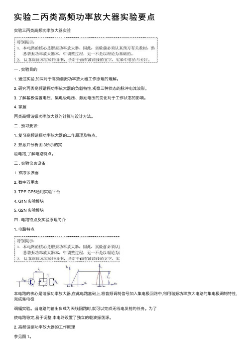
实验⼆丙类⾼频功率放⼤器实验要点实验三丙类⾼频功率放⼤器实验⼀ . 实验⽬的1. 通过实验,加深对于⾼频谐振功率放⼤器⼯作原理的理解。
2. 研究丙类⾼频谐振功率放⼤器的负载特性,观察三种状态的脉冲电流波形。
3. 了解基极偏置电压、集电极电压、激励电压的变化对于⼯作状态的影响。
4. 掌握丙类⾼频谐振功率放⼤器的计算与设计⽅法。
⼆ . 预习要求:1. 复习⾼频谐振功率放⼤器的⼯作原理及特点。
2. 熟悉并分析图 3所⽰的实验电路,了解电路特点。
三 . 实验仪表设备1. 双踪⽰波器2. 数字万⽤表3. TPE-GP5通⽤实验平台4. G1N 实验模块5. G2N 实验模块四 . 电路特点及实验原理简介1. 电路特点本电路的核⼼是谐振功率放⼤器,在此电路基础上,将⾳频调制信号加⼊集电极回路中,利⽤谐振功率放⼤电路的集电极调制特性,完成集电极调幅实验。
当电路的输出负载为天线回路时,就可以完成⽆线电发射的任务。
为了使电路稳定,易于调整,本电路设置了独⽴的载波振荡源。
2. ⾼频谐振功率放⼤器的⼯作原理参见图 1。
谐振功率放⼤器是以选频⽹络为负载的功率放⼤器,它是在⽆线电发送中最为重要、最为难调的单元电路之⼀。
根据放⼤器电流导通⾓的范围可分为甲类、⼄类、丙类等类型。
丙类功率放⼤器导通⾓θ<900,集电极效率可达 80%, ⼀般⽤作末级放⼤,以获得较⼤的功率和较⾼的效率。
图 1中, V bb 为基极偏压, V cc 为集电极直流电源电压。
为了得到丙类⼯作状态, V bb 应为负值,即基极处于反向偏置。
u b 为基极激励电压。
图 2⽰出了晶体管的转移特性曲线,以便⽤折线法分析集电极电流与基极激励电压的关系。
V bz 是晶体管发射结的起始电压(或称转折电压。
由图可知,只有在 u b 的正半周,并且⼤于V bb 和 V bz 绝对值之和时,才有集电极电流流通。
即在⼀个周期内,集电极电流 i c只在 -θ~+θ时间内导通。
3005使用说明书
第4页
DCAP-3005(V2.0D)自闭贯通保护测控装置:使用说明书
说明
装置工作电源 控制回路电源
1 可以是 DC220V 或 DC110V,在订货时须注明。 1 可以是 DC220V 或 DC110V,在订货时须注明。
开关控制回路
1
交流输入(AD) 14
开关量输入
12
(DI)
有内置防跳继电器及合闸保持继电器。
途径:交流量→内部小互感器(隔离变换)→低通滤波→A/D 转换 (数字信号)→DSP(计算处理)。 均经光电隔离。其中,开入量 1~9 为 DC220V 或 DC110V 输入的 普通信号;开入量 10 可作为 GPS 对时信号,开入量 11~12 可 作为电度脉冲信号,此时它们都是 DC24V 输入,而当它们作为 普通信号时,输入电压同开入量 1~9。
可检测 12 路遥信量,遥信变位信息及同时产生的 SOE 可上传给主机。
遥控量 当地报告记录
对时功能
可接受并执行主机的遥控命令,遥控出口可整定。
故障告警记录。 变位报告记录。 操作记录。 主机软件对时 GPS 对时
第3页
DCAP-3005(V2.0D)自闭贯通保护测控装置:使用说明书
数据的掉电保存 其它
录波数据、故障告警记录、变位记录、操作记录等保存在有备用电池支 持的 RAM 中,在装置掉电时数据不会丢失。 保护或控制参数保存在 EEPROM 中,在装置掉电或电池耗尽时数据不会 丢失。 测量量显示方式:“一次值/二次值”可选择; 电度测量方式:“脉冲方式/计算方式”可选择。
3 装置硬件资源配置
名称 数量
第2页
DCAP-3005(V2.0D)自闭贯通保护测控装置:使用说明书
绝缘 导通测试仪 3131A 使用说明

使用说明绝缘/导通测试仪MODEL 3131A目录1. 安全警告2. 特性3. 性能规格4. 仪表布局5. 测量准备5.1 盒盖5.2 零调整5.3 检查电池电压5.4 连接测试探棒5.5 检查测试探棒6. 测量6.1 被测回路电源检测及断开6.2 绝缘电阻测试6.3 导通测量(电阻测试)6.4 连续测试7. 背光灯功能8.更换电池8.1 更换电池8.2 更换保险丝9. 附件9.1 肩带与测试探棒的安装10. 清洁1. 安全警告z设计符合以下国际安全规格IEC 61010-1 CAT . III 600V污染度2IEC61010-2-31 手持型探棒安全规格IEC61557-1/2/4 低压配电系统测试设备IEC60529(IP54)防水防尘IEC61326 EMC说明书中包括警告和安全规则,用户必须严格遵守以确保操作安全。
因此,使用前,务必通读操作指示。
警告●使用前,通读并理解说明书。
●请随身携带说明书以确保可随时参阅。
●必须由专业工程师严格按说明书中内容操作,任何错误操作造成的人身事故或仪器受损,共立(KYORITSU)公司概不负责。
●理解并遵守这本说明书中的安全操作说明。
必须遵守上述操作说明,如不遵守,测量时可能会导致人身伤害和仪表的毁坏。
仪表上标志,提醒用户在安全操作时,必须参阅说明书中的相关操作说明。
请务必阅读说明书中标志后的操作说明。
危险:表示操作不当导致严重或致命的伤害可能性很高。
警告:表示操作不当可能会导致严重或致命的伤害。
小心:表示操作不当可能会导致人身伤害或仪表的毁坏。
危险●请勿在通电回路中使用。
●请勿在可燃性气体的环境里进行测量,否则,可能会产生火花引起爆炸。
●测量时请握在测试线保护栏后。
●仪器表面或手潮湿时请勿测量。
●测量时不要打开电池盖。
警告●非正常情况下不要进行测量,例如:机体损坏,仪器或测试线金属部件的裸露。
●测试线连接被测设备时,请勿变更量程。
●请勿对仪器进行更换部件或改造。
UEI IRT803 600V AC DC数字绝缘电阻测试器说明书
INSTRUCTION MANUALENGLISHIRT803600V AC/DC Digital Insulation Resistance Tester1-800-547-5740email:****************TABLE OF CONTENTSFEATURES (3)GENERAL SPECIFICATIONS (3)IMPORTANT SAFETY WARNINGS (4)SYMBOLS (5)CATEGORY DEFINITIONS (5)OVERVIEW ..........................................................................................................................................6 - 7 OPERATING INSTRUCTIONSVoltage <600V AC/DC (7)Earth-Bond Resistance <20kΩ (8)Continuity (9)Insulation Resistance/1000V/ 500V/ 250V/ 100V (10)Polarization Index & Dielectric Absorption Ratio (1000V, 500V, 250V, 100V) (11)Compare Function (12)Test Lead Notes (12)Testing the Fuse (13)Testing the Batteries (13)Battery Replacement (14)Fuse Replacement (14)Remote Probe Set (15)FCC/IC INFORMATION (16)DISPOSAL (16)CLEANING (16)STORAGE (16)WARRANTY (16)GENERAL SPECIFICATIONS• Operating Temperature: 32˚ to 122˚F (0˚ to 50˚ C)• Storage Temperature: 14˚ to 122˚F (-10˚ to 50˚C)• Operating Humidity: <75%• Operating Altitude: 6,562 ft (2000m)• Pollution Degree: 2• Backlight: Yes • Refresh Rate: 3/sec• Over-range: “OFL” is displayed.• Dimensions: 8.27” x 3.52” x 2.17” • Item Weight: 1.283 lbs.• Calibration: Recommended annually • CAT Rating: CATIV 600V/CATIII 1000V• Certifications: cETLus 3rd edition, CE Conformity, CATIV 600V, CATIII 1000V, IP42, RoHS, 6’ Drop Protection, IEC/EN 61010-1: 2010• Battery Type: (AA) 4• Test Leads: Silicone test leads w/ alligator clips (red and black) (ATL57), Remote Probe • Accuracy Temperature: 64˚ to 82˚F (18˚ to 28˚C)• Temperature Coefficient: Nominal 0.1 x (Specified accuracy)/˚C • Bargraph: 30 segmentsFEATURES• Insulation Resistance 20.0GΩ• 600V AC/DC• Earth-bond Resistance 20.00kΩ• Continuity • PI/ DAR test • Hold• Test lead holders in boot • Zero reading • Lock reading• Compare reading • Rotary dial selector • Protective rubber boot • Kick stand • Remote probe • Auto power off • Backlit Display • WorklightIRT803 Insulation resistance tester is designed to help prevent hazards such as electric shock and short-circuits caused when the insulation in electrical devices, parts, and equipment used in plants, buildings, and other settings degrades over long periods of use.IMPORTANT SAFETY WARNINGSWARNINGRead entire Safety Notes section regarding potential hazard and proper instructions before using this meter. In this manual the word “WARNING” is used to indicate conditions or actions that may pose physical hazards to the user. The word “CAUTION” is used to indicate conditions or actions that may damage this instrument.WARNINGTo ensure safe operation and service of the tester, follow these instructions. Failure to observe these warnings can result in severe injury or death.WARNING• Before each use, verify meter operation by measuring a known voltage.• Never use the meter on a circuit with voltages that exceed the category based rating of this meter.• Do not use this meter during electrical storms or in wet weather.• Do not use the meter or test leads if they appear damaged.• Ensure meter leads are fully seated and keep fingers away from the metal probe contact when making measurements. Always grip the leads behind the finger guards molded into the probe.• Do not open the meter to replace batteries while the probes are connected.• To avoid false readings that can lead to electrical shock, replace batteries if a low battery indicator appears.• Unless measuring voltage, shut off and lockout power before measuring resistance.• Always adhere to national and local safety codes. Use proper personal protective equipment (PPE) to prevent shock and arc blast injury where hazardous live conductors are exposed.• Always turn off power to a circuit or assembly under test before cutting, unsoldering or breaking the current path. Even small amounts of current can be dangerous.• Always disconnect the live test lead before disconnecting the common test lead from the circuit.• In the event of electrical shock, ALWAYS bring the victim to the emergency room for evaluation, regardless of victim’s apparent recovery. Electrical shock can cause unstable heart rhythms that may need medical attention.• If any of the following occur during testing, turn off the power source to the circuit being tested: arching, flame, smoke, extreme heat, smell of burning materials or discoloration or melting of components.WARNINGHigher voltages require greater awareness of physical safety hazards. Before connecting the test leads; turn off power to the circuit under test, set meter to the desired function and range; connect the test leads to the meter first, then connect to the circuit under test. Reapply power. If an erroneous reading is observed, disconnect power immediately and recheck all settings and connections.WARNINGThis meter is designed for trade professionals who are familiar with the hazards of their trade. Observe all recommended safety procedures that include proper lockout utilization and use of personal protective equipment that includes safety glasses, gloves and flame resistant clothing.SYMBOLSDC (Direct current)AC (Alternating Current) Auto Power Off Active Negative DCLow Battery High VoltageVoltage ContinuityOhms/Resistance COMPARE CompareWarning or CautionFuseKiloMegaG GigaPI/DAR Greater ThanZEROGround30 Segment BargraphMeasurement Category Short-Circuit (typical)kA aLocation in thebuilding installationII< 10Circuits connected to mains socket outlets and similar points in theMAINS installationIII< 50Mains distributions parts of the buildingIV> 50Source of the mains installation in the buildingCATEGORY DEFINITIONSOVERVIEW AND OPERATING INSTRUCTIONSA. Worklight: Lights work area in dark environments.B. Display: High contrast and backlit.C. Apo: Auto power off after 10 minutes of useD. Select Button:• Press to start battery test in AC/DC V mode.• Press to activate Zero mode in Earth-bond resistance testing.E. PI/DAR (Polarization Index/Dielectric Absorption Ratio) Button: Use PI for test of insulation deterioration and DAR for extended insulation resistance test. • Press x1 for PI mode. • Press x2 for DAR mode.F. Back light/ Worklight Button: Press to turn on worklight and back light.G. Test Button: Start and stop measurement insulation, earth-bond resistance test and PI/PAR test. Also, used for testing the fuse.H. F unction Dial: Turns on meter and is used to select the function.I. Category Max Indicator: Maximum CAT Rating for input jacks. • Use CATIII test leads or higher• Zero/Ω Test Lead Port: Fused, used for Zero Ohms. • Common Test Lead Port:• Volt/Insulation Test Lead Port: CATIV 600V/CATII 1000V, used for Volts, Continuity and Insulation test J. Compare Button: Used to set a pass/fail compare level for insulation measurements.K. Lock Button: Locks insulation or earth-bond resistance test to ON position. When pressed before the TEST button , the test remains active until you press the lock or test button again to release the lock.L. Hold Button:• Press x1 for Hold mode.M. P rotective Rubber Boot: With molded comfortable grip.AF E BC GIDWARNING• Use CATIII rated Test leads or higher.• Do not attempt to measure more than 1000V AC/DC.• Keep hands below finger guards when measuring high voltage levels.Features:SELECTHOLD2. Input Impedance: 10MΩ (nominal), < 100pF3. Overload Protection: AC 1000V rms or DC.N. Test Lead Holders: Used for hands-free testing or storage O. Kick Stand: For easy viewing of screen when testing.P. Battery and Fuse Cover: (under protective rubber boot)Q. Serial Number (under kick stand)If the meter detects higher than AC or DC 1.5V, the meter will automatically choose AC or DC.• Short the ends of the test leads together, press the SELECT button and wait until ZERO appears. The meter measures the test leads resistance, stores the data/results in memory and subtracts it from the reading. The test lead resistance is saved even after the meter is powered off. If the Probe resistance is >2Ω, the resistance will not be saved.• Connect the test leads to the circuit to be tested. The tester will automatically detect if the circuit is energized.• The display will show “----” until a valid resistance reading is detected.• The High Voltage symbol will display if greater than 2V AC or DC is present. If the meter “chirps”when you press the TEST button, test is corrupted due to voltage being present.• Press and hold the TEST button on the Meter or Remote Probe to start test. Test stops when the button is released.Features:NOTE: When the resistance is higher than the maximum display range the tester displays the > symbol and the maximum resistance for the range.WARNING3. Short Circuit Current: > 200.0 mAHOLDWARNING• Do not measure resistance/continuity on a live circuit.• Beeper sounds constant as long as circuit is complete.• Set Rotary dial to a desired voltage position.• The display will show “----” until a valid resistance reading is obtained.• The High Voltage symbol will display if greater than 30V AC or DC is present.• Press and hold the TEST button on the Meter or Remote Probe to start the test. Test stops when TEST button is released.• Keep test leads on test points after TEST button is released. The circuit under test will then discharge.Features: LOCKPI/DAR COMPARETESTNote : When the resistance is higher than the maximum display range the tester displays the > symbol and the maximum resistance for the range.WARNINGDo not measure resistance on a live circuit.1. Measurement Range: 0.01MΩ to 20GΩ2. Test Voltages: 100, 250, 500, 1000V3. Test Voltage Accuracy: 0 to +20%4. Short-Circuit Test Current: 1mA nominal5. Auto Discharge: Discharge time <0.5 sec. for C = 1µF or less6. Live Circuit Detection: Inhibit test if terminal voltage >30V prior to initialization of test7. Maximum Capacitive Load: Operable with up to 1µF loadAbsorption Ratio (DAR) is the ratio of the 1-minute insulation resistance to the 30-second insulation resistance.Features: LOCKPI/DARTEST• Because of the time required for the PI and DAR tests, alligator clips are recommended.• Use rotary selector dial to select desired test voltage.• The display will show “----” until test starts.• The High Voltage symbol will display if greater than 30V AC or DC is present. • Press and hold the Test Button on the Meter or Remote Probe to start the test.Note: When the resistance is higher than the maximum display range the tester displays the > symbol and the maximum resistance for the range.WARNINGNEVER measure resistance on a live circuit.Use the Compare Function to set “Pass/Fail” compare levels for insulation measurements.Press the Compare Button to select the desired compare value. Choose from the following values: • 100kΩ • 200kΩ • 500kΩ • 1MΩ • 2MΩ • 5MΩ • 10MΩ • 20MΩ • 50MΩ • 100MΩ • 200MΩ • 500MΩPerform Insulation tests as described in this manual. The PASS symbol will appear on display if the measured value is greater than the selected value.Press and hold the Compare button to stop/disable the Compare function.• CAT II Measurement Locations• CAT IV shields may be removed for CAT II locations. This will allow testing on recessed conductors such as standard Test Lead category protections apply only to test leads and should not be confused with the meter’s specificCAT rating. Observe the maximum category protection indicated on the meter the test leads are plugged into.WARNING: To avoid electrical shock or injury, remove the test leads and any input signals/voltages before replacing the fuse.• Turn the rotary selector dial to (ZERO/Ω) position.• Press and hold the Test Button . If the display shows “FUSE” the fuse is bad and should be replaced. Please see Fuse Replacement section of this manual.The meter continuously monitors battery voltage. If the Low Battery indicator is displayed, replace the batteries.To manually test the batteries:• Turn the rotary selector dial to the Battery/Voltage position, with no test leads connected.• Press the Select button to start the battery test. The battery voltage is displayed for 5 seconds. Then the voltage function is displayed again.•When the batteries are too low for safeoperation, the Low Battery indicator will display• Remove protective rubber boot.• Remove battery cover.• Replace the batteries (4 AA).• Replace the battery cover •Replace the protective rubber boot.• Remove protective rubber boot.• Remove battery cover.• Replace the fuse (F 440mA 1000V 1R 10kA).• Replace the battery cover.• Replace the protective rubber boot.rubber boot.cover.rubber boot.cover.1. Explanation of symbolsSymbols Description: Double insulation: See accompanying user manual2. Intended use and color of the lead SetA) Test probe has the lead wire which is composed of the Nickel Silver, Copper Braid, and PVC Rubber. O ne end has a plugand the other end is 4mm (with cap)or 18mm (without cap) probe tip.B) Probe length : 1618 mm ± 5.0 mmC) Wire Color : Black / dimensions : ¢ 6mmD) Weight : 126g3. Specification (Dual rating)Voltage (a.c/d.c) : 1000 V Current : Max. 10 AMeasurement Category : CAT II (without Caps) / CAT III, CAT IV (with Caps)4. Identification of operation controlThe test probe is generally attached with Digital Multi-meter. It must be in accordance with the r elating meter.(UL 61010-031, CAT II 1000V, CAT III 1000V, CAT IV 600V, 10A)5. WARNING• Before testing, make sure the test probe is connected to the meter. Make sure that the test probe is d isconnected from the test point before the test probe is without connection to the meter.• If this product is used in manner not specified by the instructions, the protection may be impaired. R eplace leads that have the inner contrasting color of the wire exposed.• Do NOT use test probe in CAT III or CAT IV environments without the cap is assembled with test p robe and correct category rating visible on the cap. When the cap is not assembled with test probe, t he probe tip is 18mm and rated to CAT II 1000V.• When used with meter or other accessories, the lowest category rating of the combination applies.6. Instructions for cleaningWipe the dirty parts with gauze or soft cloth soaked with dilute detergent. After cleaning, leave the test p robe until it dries completely.WARNING - Before cleaning the test probe, make sure the test probe is disconnected from Meter and t est point.FCC/IC INFORMATIONNOTE: this device complies with part 15 of the fcc rules and can ices-3(a).Operation is subject to the following two conditions: (1) this device may not cause harmful interference, and (2) this device must accept any interference received, including interference that may cause undesired operations.INFORMATION TO THE USERThis equipment has been tested and found to comply with the limits for a class b digital device, pursuant to part 15 of the FCC Rules. These limits are designed to provide reasonable protection against harmful interference in a residential installation. This equipment generates, uses and can radiate radio frequency energy and, if not installed and used in accordance with the instructions, may cause harmful interference to radio communications. However, there is no guarantee that interference will not occur in a particular installation. If this equipment does cause harmful interference to radio or television reception, whichcan be determined by turning the equipment off and on, the user is encouraged to try to correct the interference by one or more of the following measures:• Reorient or relocate the receiving antenna.• Increase the separation between the equipment and receiver.• Connect the equipment into an outlet on a circuit different from that to which the receiver is connected.• Consult the dealer or an experienced radio/tv technician for help.WARNING any changes or modifications not expressly approved by the manufacturer, could void the user’s authority to operate equipment.DISPOSALCAUTION:This symbol indicates that equipment and its accessories shall be subject to separate collection and correct disposal.CLEANINGPeriodically clean your meter’s case using a damp cloth. DO NOT use abrasive, flammable liquids, cleaning solvents, or strong detergents as they may damage the finish, impair safety, or affect the reliability of the structural components.STORAGERemove the batteries when instrument is not in use for a prolonged period of time. Do not expose to high temperatures or humidity. After a period of storage in extreme conditions exceeding the limits mentioned in the General Specifications section, allow the instrument to return to normal operating conditions before using it.WARRANTYThe IRT803 is warranted to be free from defects in materials and workmanship for a period of 1 year from the date of purchase. If within the warranty period your instrument should become inoperative from such defects, the unit will be repaired or replaced at UEi’s option. This warranty covers normal use and does not cover damage which occurs in shipment or failure which results from alteration, tampering, accident, misuse, abuse, neglect or improper maintenance. Batteries and consequential damage resulting from failed batteries are not covered by warranty.Any implied warranties, including but not limited to implied warranties of merchantability and fitness for a particular purpose, are limited to the express warranty. UEi shall not be liable for loss of use of the instrument or other incidental or consequential damages, expenses, or economic loss, or for any claim or claims for such damage, expenses or economic loss.A purchase receipt or other proof of original purchase date will be required before warranty repairs will be rendered. Instruments out of warranty will be repaired (when repairable) for a service charge.For more information on warranty and service, contact:•Email:****************1-800-547-5740This warranty gives you specific legal rights. You may also have other rights, which vary from state to state.。
UT5583 绝缘电阻测试仪 用户手册说明书

绝缘电阻测试仪用户手册REV 02023.07尊敬的用户:您好!感谢您选购全新的优利德仪器,为了正确使用本仪器,请您在本仪器使用之前仔细阅读本说明书全文,特别有关“安全注意事项”的部分。
如果您已经阅读完本说明书全文,建议您将此说明书进行妥善的保管,与仪器一同放置或者放在您随时可以查阅的地方,以便在将来的使用过程中进行查阅。
优利德科技(中国)股份有限公司版权所有。
如果原购买者自购买该产品之日起三年内,将该产品出售或转让给第三方,则保修期应为自原购买者从UNI-T或授权的UNI-T分销商购买该产品之日起三年内。
探头及其他附件和保险丝等不受此保证的保护。
如果在适用的保修期内证明产品有缺陷,UNI-T可自行决定是修复有缺陷的产品且不收部件和人工费用,或用同等产品(由UNI-T决定)更换有缺陷的产品。
UNI-T作保修用途的部件、模块和更换产品可能是全新的,或者经修理具有相当于新产品的性能。
所有更换的部件、模块和产品将成为UNI-T的财产。
以下提到的“客户”是指据声明本保证所规定权利的个人或实体。
为获得本保证承诺的服务,“客户”必须在适用的保修期内向UNI-T通报缺陷,并为服务的履行做适当安排。
客户应负责将有缺陷的产品装箱并运送到UNI-T指定的维修中心,同时预付运费并提供原购买者的购买证明副本。
如果产品要运送到UNI-T维修中心所在国范围内的地点,UNI-T应支付向客户送返产品的费用。
如果产品送返到任何其他地点,客户应负责支付所有的运费、关税、税金及任何其他费用。
本保证不适用于由于意外、机器部件的正常磨损、在产品规定的范围之外使用或使用不当或者维护保养不当或不足而造成的任何缺陷、故障或损坏。
UNI-T根据本保证的规定无义务提供以下服务:a) 修理由非UNI-T服务代表人员对产品进行安装、修理或维护所导致的损坏;b) 修理由于使用不当或与不兼容的设备连接造成的损坏;c) 修理由于使用不符合本说明书要求的电源而造成的任何损坏或故障;d) 维修已改动或者与其他产品集成的产品(如果这种改动或集成会增加产品维修的时间或难度)。
FT300A 系列材料电阻率测试仪.docx
FT-300A系列材料电阻率测试仪
本仪器本仪器采用四端测量法适用于生产企业、高等院校、科研部门,实验室是检验和分析导体材料和半导体材料质量的一种重要的工具。
木仪器配置各类测量装置可以测试不同材料之电阻率。
液晶显示,无需人工计算,并带有温度补偿功能,电阻率单位自动选择,仪器自动测量并根据测试结果自动转换量程,无需人工多次和重复设置oFT-300A系列材料电阻率测试仪恒流源输出保证测试结果的准确性及测试的稳定度;FT-300A系列材料电阻率测试仪选配:配备软件可以由电脑操控,并保存和打印数据,自动生成报表,木仪髀采用4.3吋大液晶屏幕显示, 同时显示电阻值、电阻率、电导率值、温度、压强值、单位自动换算,配豊不同的测试治具可以满足不同材料的测试要求。
测试治具可以根据产品及测试项目要求选购•使用薄膜按键开关面板,操作简单,耐用,符合人体工学操作规范.
相关产品:FT-310炭素电阻率测试仪;FT-3O3表而电率阻率/体积电阻率测试仪; FT-304绝缘材料表面/体积电阻率测试仪;FT・302电缆半导电屏蔽层电阻率测试仪;FT-300经济型粉末电阻率测试仪;FT-300A材料电阻率测试仪;FT-300B电线电缆电阻率测试仪;FT-320材料超低电阻及电阻率测试仪;FT-300C材料电导率测试仪;FT-300D方块屯阻测试仪;FT-301多功能粉末电阻率测试仪
ROOKO懾柯品牌,来自瑞柯仪器公司,一个专注于改变人们生活方式和品质的企业.
专业与精致并重;优秀与智慧之原。
KPA300系列单相数字电参数测量仪使用说明书
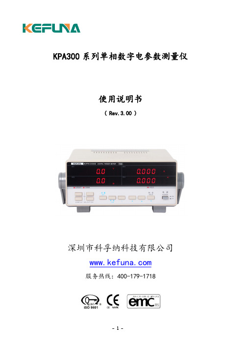
KPA300系列单相数字电参数测量仪使用说明书( Rev.3.00 )深圳市科孚纳科技有限公司服务热线:400-179-1718目录第一章主要性能及技术指标 (3)第二章使用说明 (8)第三章串行口使用说明 (20)第四章继电器串使用说明 (21)第五章装箱清单 (21)第六章使用注意事项及故障排除方法 (22)第一章 主要性能及技术指标KPA300系列单相数字电参数测试仪采用了先进的32位高速处理器和双路24位AD 转换器,具有高精度、宽动态范围、结构紧凑灵巧等特点,是新一代数字化电参数测量仪器,可以测量有效值电压、电流、有功功率、视在功率、无功功率、电能累计、电能计时、频率、功率因数。
产品符合标准《DB37/T557-2005数字式电参数测量(试)仪》。
产品适用的型式批准证书编号:89E0105-37。
测试原理为:电压有效值为: Urms=(∫0T V 2(t)dt/T)1/2电压直流分量为: Udc=∫0T V(t)dt/T电流有效值为: Irms=(∫0T I 2(t)dt/T)1/2电流直流分量为: Idc=∫0TI(t)dt/T电压交流分量为: Uac=(Urms 2-Udc 2)1/2电流交流分量为: Iac=(Irms 2-Idc 2)1/2有功功率为: P=∫0TV(t)• I(t)dt/T 视在功率为: S =Urms• Irms 功率因数为: PF=P/(Urms*Irms) 无功功率为: Q =(S 2- P 2)1/2选型说明 型号后缀代码 说明KPA300无标准型号 T 订制型号 A4 交流20mA-40A A6交流20mA-60A 接口 -R2 通信功能RS232 任选其一-R4 通信功能R485选件 /R 继电器接口(上下限报警输出) /EXT外部输入(电流钳或霍尔传感器)KPA300系列单相电参数测量仪-基本型功率,适合于生产线测试,可提供电流钳功能注意:订货时请对测试对象及特殊的技术要求、使用要求进行特别说明。
测试300排气测试仪指南说明书

• Operation via smart-touch – The smart-touch display respondsimmediately without any delay. Thatallows intuitive operation – just as easy as on your smartphone.• E-mailing of reports – The testo 300 enables the convenientcreation of documentation directly on site. Y ou can send reports to the office or customers straight away via WLAN.• Keep an eye on all the measuring values – Y ou can see all thesystem’s parameters straight away on the large 5˝ HD display.• Get the result faster – Clearly structured menus for all relevant measurements are already stored in the measuring instrument and guide you efficiently through the application.• Ready to use straight away – No more waiting time. In standby mode, the testo 300 is ready to measure at the touch of a button.• Completely worry-free – The testo 300 has quality sensor technology with up to 6 years’ service life, measures high CO values up to 30,000 ppm and is future-proofed thanks to NO preparation.A contemporary flue gas analyzer should not just provide reliably accu-rate results – that is a must. The really key issue is making everything as easy as possible for you, both before and after the measurement, as well as in terms of the measurement itself. And doing this every single day.The user-friendly and highly efficient testo 300 was developed with this objective in mind. It is not just the fruit of decades of experience in mea-suring technology. With smart-touch operation, robust construction and e-mailing of reports, the testo 300 will quickly become your indispensable companion for all measuring tasks in-volving heating.TRUL Y ROBUST:Smart measuring technology is of lit-tle benefit if it does not keep going in tough day-to-day working conditions. Because your measuring instrument is a partner that supports you every day in the efficient, problem-free performance of your tasks. This is precisely why the testo 300 has a particularly resilient and high-quality construction. Special challenges can thus easily be met across workshops, transport vehicles and boiler rooms.Flue gas measurement truly smart.Welcome to the Smart World of Testo.TESTO 300Protected displayScratch-resistant, recessed and with a special replaceable protective film.Secure mounting4 strong magnets with rubber coating – particularly material friendly.Robust sensorsOptional: extremely durable O₂ sen-sor and automatic dilution up to 30,000 ppm CO.Truly flexible:Instrument configuration and probe system.A FLUE GAS ANAL YZER PERFECTL Y TAILORED TO YOUR NEEDSThe testo 300 doesn’t just give you smart operation – the configuration also has that certain something. This means you can choose between a 2-year and 4-year warranty for the sensor technology. In addition to O₂ and CO, you can also add a third sensor slot for the measurement of NOx as an option. And various kits with special instrument configurations and individual accessories are available, spe-cifically tailored to the requirements of heating engineers and chimney sweeps.One handle for a variety of probesA variety of probe shafts can easilybe attached to the multi-functionalhandle. This ensures you enjoy ahigh level of flexibility in all applica-tions. And you are ready to measureeven more quickly, thanks to connec-tion via a universal plug.Proven probesY ou can use the testo 320, testo 330and testo 330-1/-2 LL probes withtheir practical multiple plug for thetesto 300 as well.New probesNew probes with anti-rotation USB Cconnection are available for tempera-ture measurement, for example offlow and return temperatures, alongwith ambient CO measurement.testo interface functionThe testo 300 provides an interface with a variety of industry software. This enablesyou to access the testo 300’s readings with your terminal devices and tools and todocument them or further process them in your industry software.76-D-6000-04.01TESTO 300Truly intuitive: The menus.Flue gas values as a graphicSee all the readings in a graphic pro-gression display – and identify, for in-stance, how the flue gas loss relates tothe CO value.SmartTouchCreate measurement protocols withIntuitive measurement menusClearly structured and explicit menusfor all applications involving heatingsystems are already stored in thetesto 300. This allows you to do yourLonglife sensorsHigh-end sensors with a service life of up to 6 years for intensive use (several times a day). At least one sensor replacement is saved in the course of a normal working life.Instrument models.Spare gas sensors/retrofitting Order no.O₂ sensor, with 4 years' warranty0393 0023CO sensor (without H₂ compensation), with 4 years' warranty 0393 0051CO sensor (without H₂ compensation), with 2 years' warranty 0393 0053CO sensor, H₂-compensated, with 4 years' warranty 0393 0101CO sensor, H₂-compensated, with 2 years' warranty 0393 0105NO sensor0393 0151AccessoriesOrder no.testo Bluetooth ®printer, including 1 roll of thermal paper, rechargeable battery and mains unit, for instruments including the testo 300, testo 330i and testo 4400554 0621Spare thermal paper for printer, permanent ink0554 0568Smoke tester, including oil and soot papers for measuring soot in flue gas, excluding cone (order no. 0554 9010)0554 0307Filter paper for determining soot number, 40 measuring strips for approx. 200 measurements 0554 0308USB mains unit, including USB cable0554 1105testo EasyHeat PC software for displaying measurement procedures as diagrams, tables and for customer data management0554 3332ISO calibration certificate for flue gas0520 0003Cases and carrying bagsOrder no.Instrument case (height: 130 mm) for instrument, probes and accessories0516 3300Instrument case with double base (height: 180 mm) for instrument, probes and accessories 0516 3301testo 300 instrument bag with carrying strap0516 3001INSTRUMENT MODELS.TECHNICAL DATAO₂ measurement 0 to 21 vol.%±0.2 vol.% 0.1 vol.%CO measurement (without H₂ compensation)0 to 4,000 ppm ±20 ppm (0 to 400 ppm)±5% of m.v. (401 to 2,000 ppm)±10% of m.v. (2001 to 4,000 ppm)1 ppmCO measurement (with H₂ compensation)0 to 8,000 ppm ±10 ppm or ± 10% of m.v. (0 to 200 ppm)±20 ppm or ± 5% of m.v. (201 to 2,000 ppm)±10% of m.v. (2,001 to 8,000 ppm)1 ppmCO measurement(without H₂ compensation anddilution)0 to 15,000 ppm ±200 ppm or ± 20% of m.v. 1 ppmCO measurement(with H₂ compensation and dilution)0 to 30,000 ppm ±100 ppm or ± 10% of m.v. 1 ppmNO measurement 0 to 3,000 ppm ±5 ppm (0 to 100 ppm)±5% of m.v. (101 to 2,000 ppm)±10% of m.v. (2,001 to 3,000 ppm)1 ppmEfficiency testing (Eta) 0 to 120% 0.1% Flue gas loss 0 to 99.9% 0.1%CO₂ determination (digital calculation from O₂)Display range 0 toCO₂ max.±0.2 vol.% 0.1 vol.%Draught measurement -9.99 to +40 hPa ±0.005 hPa (0 to 0.1 hPa)±0.02 hPa (0.1 to +3.00 hPa)±1.5% of m.v. (+3.01 to +40 hPa)0.001 hPa (0 to 0.1 hPa) 0.01 hPa (remaining meas. range)4 Pa measurement(for instruments with dilution)-50 to +50 Pa ±0.3 Pa (< 10 Pa)±3% of m.v. (remaining meas. range)0.1 PaPressure measurement -100 to 200 hPa ±0.5 hPa (0 to +50.0 hPa)±1% of m.v. (+50.1 to +100.0 hPa)±1.5% of m.v. (+100.1 to +200 hPa)0.01 hPaTemperature (instrument) -40 to +1,200°C ±0.5°C (0.0 to +100.0°C)±0.5% of m.v. (remaining meas. range)0.1°C (-40 to +999.9°C) 1°C (remaining meas. range)Ambient CO measurement (internal/flue gas probe)0 to 2,000 ppm ±10 ppm (0 to 100 ppm)±10% of m.v. (101 to 2,000 ppm)1 ppmAmbient CO measurement (external with CO probe)0 to 500 ppm ±3 ppm (0 to 29 ppm)±10% of m.v. (30 to 500 ppm)1 ppm76-D-6000-04.01。
TH9320交直流耐压绝缘电阻测试仪器说明书
TH9310/20 系列用户手册 Ver1.1.6
------------------------------
2014.6
TH9310/20 系列仪器使用说明书
Ver1.1.6
目录
第 1 章 开箱安装 ______________________________________________________________ 1 1.1 开箱检查 _____________________________________________________________ 1 1.2 使用注意事项 _________________________________________________________ 2 1.3 移动时的注意要点 _____________________________________________________ 3 1.4 检查电源和保险丝 _____________________________________________________ 3 1.5 连接交流电源线 _______________________________________________________ 4 1.6 接地 _________________________________________________________________ 4 1.7 操作检查 _____________________________________________________________ 5 1.8 仪器的其它特性 _______________________________________________________ 5 第 2 章 操作规范和措施 ________________________________________________________ 6 2.1 禁止的操作行为 _______________________________________________________ 6 2.2 紧急情况的处理 _______________________________________________________ 6 2.3 测试中的预防措施 _____________________________________________________ 6 2.4 高压测试警告 _________________________________________________________ 7 2.5 有故障仪器的危险状态处理 _____________________________________________ 8 2.6 保证长时间无故障使用的条件 ___________________________________________ 8 2.7 日常检查 _____________________________________________________________ 8 第 3 章 仪器面板概述 __________________________________________________________ 9 3.1 前面板说明 ___________________________________________________________ 9 3.2 后面板说明 __________________________________________________________ 11 3.3 多通道模块说明 ______________________________________________________ 12 3.4 仪器性能概述 ________________________________________________________ 13 第 4 章 基本操作 _____________________________________________________________ 17 4.1 仪器界面结构概述 ____________________________________________________ 17 4.2 面板功能界面和参数说明 ______________________________________________ 18 4.2.1 SETUP 测量设置 _______________________________________________ 20 4.2.2 TEST 测试界面 ________________________________________________ 21 4.2.3 SYSTEM 系统界面 ______________________________________________ 22 4.2.4 FILE 文件存储界面。___________________________________________ 24 4.3 测试项目界面和参数说明 ______________________________________________ 26 4.3.1 AC 交流耐压测试参数设定 ______________________________________ 26 4.3.2 DC 直流耐压测试参数设定 ______________________________________ 27 4.3.3 IR 绝缘电阻测试参数设定 _______________________________________ 28 4.3.4 OS 开短路检测测试参数设定 ____________________________________ 29 4.3.5 MF 多路辅助控制设定 __________________________________________ 30 4.4 测试功能原理与使用说明 ______________________________________________ 31 4.4.1 启动测试 _____________________________________________________ 31 4.4.2 测试时延 _____________________________________________________ 31 4.4.3 电压上升 _____________________________________________________ 32
致新精密 ZX9501交直流耐压绝缘测试仪操作说明书

使用说明书O P E R A T I O N M A N U A L交直流耐压绝缘测试仪ZX9501系列公司:常州市致新精密电子有限公司电话:*************传真:*************网址:邮箱:*****************注意事项:本说明书版权归常州市致新精密电子有限公司所有,并保留所有权利。
未经常州市致新公司书面同意,不得对本说明书的任何部分进行影印、复制或转译。
本说明书中,常州致新、致新精密、ZXP均指常州市致新精密电子有限公司,保留所有权利。
本说明书包含的信息可能随时修改,恕不另行通知。
最新的说明书电子文档可以从常州致新网站下载:2017年01月……………第3版(制造编号:2017-HV-L-003)公司声明本说明书所描述的可能并非仪器所有内容,常州市致新精密电子有限公司有权对本产品的性能、功能、内部结构、外观、附件、包装物等进行改进和提高而不作另行通知!由此引起的说明书与仪器不一致的困惑,可与我公司联系。
安全警告:仪器接地连接电源时,请确认电源插座含有接地线。
如未接地,则机壳上就有带静电或感应电的危险,可能会造成人身伤害!触电危险操作、测试与仪器维护时谨防触电,非专业人员请勿擅自打开机箱,专业人员如需更换保险丝或进行其它维护,务必先拔去电源插头,并在有人员陪同情况下进行。
即使已拔去电源插头,电容上电荷仍可能会有危险电压,应在放电后再行操作。
仪器前面板高压输出端子带有高压,请任何时候都不要用手触摸,避免触电。
请勿擅自对仪器内部电路及元件进行更换和调整电击损害任何在测试过程不正确取下或加上被测件会由于测试端的高压造成人身、财物的异常损害!!!任何时候都不要用手直接触摸测试端子。
输入电源请按本仪器规定的电源参数要求使用电源,不符合规格的电源输入可能损坏本仪器。
更换保险丝请使用相同规格。
电子仪器不可以在易燃易爆气体环境中使用,或者在含有腐蚀性气体或烟尘环境中使用,避免带来危险其它安全事项请不要向本仪器的测试端子施加任何电压源或电流源。
关于直流绝缘在线监测装置QDA-300 误选线分析处理
关于直流绝缘在线监测装置QDA-300 误选线分析处理摘要:2015至2016年期间,某燃机电厂对机组所有直流绝缘在线监测装置进行升级。
针对新装QDA-300装置在调试验收过程中,装置出现不同现象的误选问题。
经过查实,针对真实接地、不同电源回路环网运行、电磁干扰等不同的原因,提出改进措施,取得了预期的效果。
关键词:直流绝缘在线监测装置;直流接地;环网运行;电磁干扰前言发电厂和变电站的直流电源作为主要电气设备的保安电源,以及继电保护装置、控制装置等重要负载提供工作电源,是一个十分庞大的多分支供电网络。
直流系统工作状况好坏直接影响电力系统安全、可靠和高效运行。
直流接地是直流系统常见的故障,可能造成控制回路和继电保护装置的误动作,从而引发严重的事故。
因此必须对直流系统绝缘状况进行长期在线监测。
为了有效提高排除直流接地故障的效率,直流在线绝缘监测装置应具备可靠的接地选线功能。
一、情况简介某燃机电厂各直流系统原采用的直流绝缘在线监测装置(爱默生JYM-Ⅱ)并不具备实时检测直流系统窜入交流电源的功能。
通过对比,选择广州千顺电子设备有限公司生产的QDA-300型直流在线绝缘监测装置。
利用机组停运机会,分批次对全厂各直流系统绝缘在线监测装置进行更换。
某燃机电厂1号联合循环机组,此次改造共安装了4套QDA-300系列的绝缘监测装置。
分别是2套直流110V系统、1套直流120V系统、1套直流220V系统。
在调试验收过程中装置出现不同现象的误选。
基本情况是:(1)、2套110V系统绝缘装置选线功能正常,没有出现接地选线报警现象;(2)、120V系统绝缘装置出现接地选线报警现象,基本固定在12、17、20、43、44支路,而且系统存在78k左右的平衡接地;(3)、220V系统的绝缘装置总共12路馈线,误选支路随机出现。
二、问题原因的分析与解决过程情况一:120V的直流系统120V直流系统目前存在78k的平衡接地(装置测量),通过对每路CT信号的检测发现12、17、20、43、44馈线支路信号异常而且也最易导致误选。
微机绝缘监测仪WJY3000A使用说明书

WJY3000A型微机绝缘监测仪使用说明书本资料为深圳奥特迅电力设备有限公司版权所有,未经公司书面许可,任何单位和个人不得摘录、复制、翻译、注释、编辑本资料的部分或全部,侵权必究。
使用前请详细阅读本说明书!策划:品质部、市场部版次:2005年5月第4版,第1次印刷印数:1-5000本目录一概述 (1)二型号命名 (1)三功能特点 (1)四技术参数 (1)五工作原理 (1)六装置说明 (2)七安装接线 (3)八键盘操作与显示 (4)九包装、运输及保管 (11)十客户服务 (11)一概述本监测仪广泛用于发电厂、变电所以及厂矿企业的直流操作电源系统中,用来对直流系统的绝缘状况进行监测,主要有母线电压、母线对地绝缘状况的自动检测、报警,直流馈电支路接地自动巡查等。
WJY-3000A微机型绝缘监测仪,是我公司总结多年运行维护经验而自主开发的升级换代新产品。
装置各功能单元采用模块化结构,基本配置由主机、电流变送器以及CT采集模块组成,主机检测正负直流母线的对地电压,通过对地电压计算出正负母线对地绝缘电阻。
当绝缘电阻低于设定的报警值时,自动启动支路巡检功能。
支路漏电流检测采用直流有源CT,不需向母线注入信号。
所有支路的漏电流检测同时进行,被检信号由CT采集后送采集模块,每个模块内含CPU,直接在CT采集模块内部转换为数字信号,由CPU通过串行口上传至绝缘监测仪主机。
增加CT以及采集模块可方便的对检测支路数进行扩展,若距离主机较远而需要扩展,可选择增加分机或CT驱动器来实现,分机或CT驱动器与主机之间也都是通过串口通讯进行数据传输。
这样支路检测精度高、速度高、抗干扰能力强,从而可靠性、适用性方面等多项技术上有了新的突破,成功地解决了目前直流接地检测装置中存在漏报误报、巡检速度慢、接线过多、安装维护困难以及扩容不方便等弊端,是一种功能完善且稳定性高的智能型直流系统绝缘监测装置。
二型号命名型号定义:WJY 3000A H F绝缘监测仪分机功能增强型设计序号系列号微机型绝缘监测仪代号三功能特点3.1一般功能a.绝缘监测系统的主机、CT采集模块以及分机采用CPU芯片控制,数据传输通过串行总线结构,集成度高,抗干扰能力强;b.采用大屏幕汉字显示,直观、明了且具有操作提示信息,便于人机对话;c.无需在直流系统中注入任何信号,对直流系统正常工作无影响;d.能消除直流供电系统对地大电容的影响;e.电流变送器能消除大电流冲击后的剩磁影响,保证CT工作的长期稳定性;f.CT采集模块与主机采用数字信号传输,大大减少了CT与主机的连接线且使用方便,检测准确,抗干扰能力强;g.用于主分屏直流系统时,装置可设为主机或分机;h.监测并显示直流系统母线电压,电压超过允许范围时发出报警信号;i.监测并显示正、负母线的对地绝缘电阻值,当绝缘电阻低于设定值时发出报警信号;并实时自动巡查各支路对地绝缘电阻;j.汉字显示历史记录,装置掉电后信息不丢失;k.母线监测有平衡桥和不平衡桥两种方式可任意选择;l.具有RS485串行接口,能和上位机终端设备实现数据通讯;m.适应多种复杂大型的直流系统,如主机可监测一段母线也可监测两段独立的母线;主机可带多台分机;分机可同时与两台主机通讯,分机可自动识别所监测支路属于哪一段母线。
UT512型数字绝缘电阻测试仪使用说明书
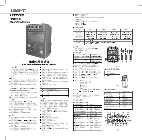
本仪器的设计、制造和检测均达到IEC61010安全标准(电子类测量产品安全要求),本手册包括确保仪器的安全使用及保证仪器的安全状态,使用者所必须遵守的警告和安全条例。
使用前请先阅读以下说明。
● 使用仪器前请先仔细阅读并理解本使用说明手册。
● 无论何时必须遵守手册的要求,并保存好手册,使 之随时能供作参考。
● 仪器测试时,错误的操作会导致事故及仪器的损 坏。
本仪器上的标志 意思是指为了安全操作本仪器,请使用者参照使用手册的相关部分操作。
危险 为了避免在某些状态及操作下、有可能引起 的严重或致命的损害。
警告 表明避免遭受电击的危险。
注意 表明避免对仪器的损害和进行准确的测量。
一.安全警告警告● 切勿测量交/直流电压在600V以上的电路。
● 请勿在易燃性场所测试,火花可能会引起爆炸。
● 如果仪器表面潮湿或操作者手是湿的请勿操作本仪 器。
● 当测量时,不可接触测试笔导电部位。
● 当测试线短路连接在仪器上时,不要按下TEST键。
● 测量时请勿打开电池盖。
● 执行绝缘测量时,不可触摸待测线路。
● 如果仪器出现异常请停止使用。
例如:仪器破损或 裸露出金属部分。
● 在电压超过33Vrms,46.7Vacrms或70Vdc的状态下工 作时一定要小心谨慎。
此类电压可能引起电击。
● 在做完高阻测量之后,待测电路中的电荷储存必须 加以释放。
● 仪器于潮湿状态下请勿更换电池。
● 确定所有测试导线与仪器的测试端口连接牢固。
● 当打开电池盖时,确保仪器已关机。
危险警告● 在测量电阻前,待测电路必须完全放电,并且与电 源电路完全隔离。
● 如测试笔或电源适配器破损需要更换,必须换上同 样型号和相同电气规格的测试笔或电源适配器。
● 电池指示器批示电能耗尽()时,不要使用仪 器。
若长时间不使用仪器,请将电池取出后存放。
● 不要在高温、高湿、易燃、易爆和强电磁场环境中 存放或使用本仪器。
● 请使用湿布或清洁剂来清洁仪器外壳,请勿使用磨 擦物或溶剂。
耐压EST-300绝缘电阻测量方法

耐压EST-300绝缘电阻测量方法
EST-300系列新一代耐压测试仪拥有先进的紧密尺寸设计,并同时保有其强大的性能。
不仅将交流耐压(ACW)、直流耐压(DCW)和绝缘阻抗(IR)功能整合到单一的机台,其尺寸与重量的轻便优势利于任何空间的摆设配置。
此外,透过仪器互连技术设计,更可以扩充功能连接接地阻抗(GB)测试仪,从而形成更完整的测试系统,提供更全面的安规测试解决方案。
第一步当然是停电啦,然后验电,在确保没电的情况下开始第二步。
第二步打开电机接线盒,拆掉所有导线接线,拆线之前要特别注意要牢记接线相序(最好写下来),以便测量完恢复接线时能保证接线的相序的正确性,如果相序接错会出现什么问题呢,那就是电机反转啦。
在实际工作时,拆线前有时会忘记记相序,怎么办呢,办法是只需在恢复的时候,把线随便接上,通电试机就行了,如果电机反转,再任意调换其中的两相接线就行了。
测量电机绝缘时,电机是不能接线的,如果电机接线了,就相当于测的是电机加导线的绝缘数值,为了精确,必须拆掉所有导线。
3005-3007A绝缘导通测试仪
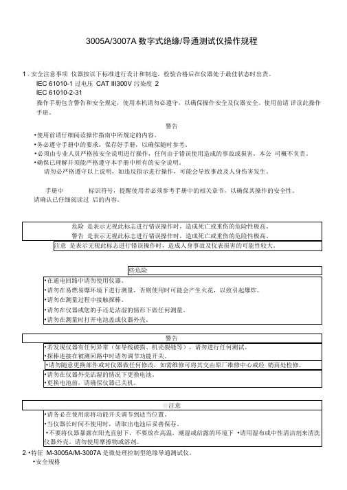
3005A/3007A数字式绝缘/导通测试仪操作规程1 .安全注意事项仪器按以下标准进行设计和制造,检验合格后在仪器处于最佳状态时出货。
IEC 61010-1 过电压CAT III300V 污染度2IEC 61010-2-31操作手册包含警告和安全规定,使用本机请勿必遵守,以确保操作安全及仪器安全。
使用前请详读此操作手册。
警告•使用前请仔细阅读操作指南中所规定的内容。
•务必遵守手册中的要求,保存好手册,以确保随时参考。
•必须由专业人员严格按安全说明进行操作,任何由于错误使用造成的事故或损害,本公司概不负责。
•确保已理解并须能严格遵守本手册中所有的安全说明。
请勿必严格遵守以上说明,如违反指示进行操作,可能会导致事故及人身伤害发生。
手册中标识符号,提醒使用者必须参考手册中的相关章节,以确保其操作的安全性。
请确认已仔细阅读过后的内容。
2 •特征M-3005A/M-3007A是微处理控制型绝缘导通测试仪。
•安全规格IEC61010-1 过电压CAT III 300V 污染度2IEC61010-2-31 (探棒安全规格)•显示屏特有背光灯,便于在昏暗处操作。
(仅3007A型)•长条图显示测量结果。
•肩带可协助双手操作。
•检测到带电线路有蜂鸣警示。
•自动放电功能绝缘电阻测量后,可自动释放线路中所存储的电量。
电压条形图可显示放电情况。
•自动关机功能为避免在测量后忘记关闭电源并延长电池使用寿命,测量结束后10分钟左右仪器将自动关机。
• LOK 模式(仅K3007A型)为防止电池损耗,一旦到达稳定读数,将自动消除测试电流。
3. 技术规格•测试量程和精确度(23± 5 C,相对湿度45-75%)•绝缘电阻量程•导通电阻量程• AC电压显示0〜600V ± 5%rdg土3dgt•测量标准数据(电源电压的中间值为8V)绝缘电阻量程:0.5 M Q时约1000次/分钟导通电阻量程:1 Q时约700 次/分钟过电压CAT III 300V 污染度2 探棒安全规格低电压分配系统的测量仪器 •操作错误(IEC 61557-2 , -4)温度:0C 和35r 电源电压:8V 〜13.8V •标准:IEC61010-1 IEC61010-2-31 IEC61557-1/2/4 IEC61326-1 EMC IEC60529 (IP54)防尘防水检测•操作系统:双重积分•显示:液晶显示屏(最大计数:1999),单位,标记,条形显示最大 30个数(Q 量程时最大20)•过量程显示:“OL'•采样率:约0.5〜2.5 次/秒•操作温度及湿度:最大相对湿度 85%寸,0 C 〜+40C •储存温度及湿度:最大相对湿度75%寸,-10 C 〜+60C •绝缘电阻:在回路和外箱间,大于50血1000V DC •耐电压:在回路和外箱间,3700V AC/1分钟 •过载保护绝缘电阻量程:1000V 量程 1200V (DC+AC p-p /10 秒 500V 量程 600V (DC+AC p-p /10 秒 250V 量程300V(DC+AC p-p /10 秒导通电阻量程:20/200/2000 Q 量程 280V (DC+AC p-p /10秒(保险丝保护) •外形:185 (L ) *167 (W ) *89 (D ) mm• 重量:900g (含电池)• 电源:8节R6P 1.5VAA 或等量电源•自动关机:测量后约10分钟自动关机。
00A绝缘电阻测试仪和绝缘电阻测试仪价格
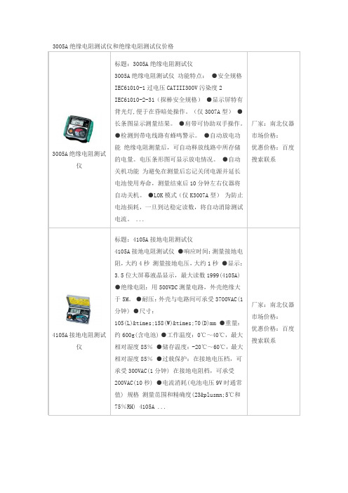
标题:4105A接地电阻测试仪
4105A接地电阻测试仪●响应时间:测量接地电阻,大约4秒测量接地电压,大约1秒●显示:3.5位大屏幕液晶显示,最大读数1999(4105A)●绝缘电阻:用500VDC测量电路,外壳绝缘大于5M。●耐压:外壳与电路间可承受3700VAC(1分钟)●尺寸:105(L)×158(W)×70(D)mm●重量:约600g(含电池)●工作温度:0℃~40℃,最大相对湿度85%●储存温度:-20℃~60℃,最大相对湿度85%●过载保护:在接地电压档,可承受300VAC(1分钟)在接地电阻档,可承受200VAC(10秒)●电流消耗(电池电压9V时通常值)规格测量范围和精确度(23±5℃和75%RH) 4105A ...
厂家:南北和绝缘电阻测试仪价格
3005A绝缘电阻测试仪
标题:3005A绝缘电阻测试仪
3005A绝缘电阻测试仪功能特点:●安全规格IEC61010-1过电压CATIII300V污染度2 IEC61010-2-31(探棒安全规格)●显示屏特有背光灯,便于在昏暗处操作。(仅3007A型)●长条图显示测量结果。●肩带可协助双手操作。●检测到带电线路有蜂鸣警示。●自动放电功能绝缘电阻测量后,可自动释放线路中所存储的电量。电压条形图可显示放电情况。●自动关机功能为避免在测量后忘记关闭电源并延长电池使用寿命,测量结束后10分钟左右仪器将自动关机。●LOK模式(仅K3ห้องสมุดไป่ตู้07A型)为防止电池损耗,一旦到达稳定读数,将自动消除测试电流。...
- 1、下载文档前请自行甄别文档内容的完整性,平台不提供额外的编辑、内容补充、找答案等附加服务。
- 2、"仅部分预览"的文档,不可在线预览部分如存在完整性等问题,可反馈申请退款(可完整预览的文档不适用该条件!)。
- 3、如文档侵犯您的权益,请联系客服反馈,我们会尽快为您处理(人工客服工作时间:9:00-18:30)。
3005A/3007A数字式绝缘/导通测试仪操作规程1.安全注意事项仪器按以下标准进行设计和制造,检验合格后在仪器处于最佳状态时出货。
IEC 61010-1 过电压CAT III300V 污染度2IEC 61010-2-31操作手册包含警告和安全规定,使用本机请勿必遵守,以确保操作安全及仪器安全。
使用前请详读此操作手册。
警告●使用前请仔细阅读操作指南中所规定的内容。
●务必遵守手册中的要求,保存好手册,以确保随时参考。
●必须由专业人员严格按安全说明进行操作,任何由于错误使用造成的事故或损害,本公司概不负责。
●确保已理解并须能严格遵守本手册中所有的安全说明。
请勿必严格遵守以上说明,如违反指示进行操作,可能会导致事故及人身伤害发生。
手册中标识符号,提醒使用者必须参考手册中的相关章节,以确保其操作的安全性。
请确认已仔细阅读过后的内容。
危险是表示无视此标志进行错误操作时,造成死亡或重伤的危险性极高。
警告是表示无视此标志进行错误操作时,造成死亡或重伤的危险性极高。
注意是表示无视此标志进行错误操作时,造成人身事故及仪表损害的可能性较大。
危险●在通电回路中请勿使用仪器。
●请勿在易燃易爆环境下进行测量,否则使用时可能会产生火花,以致引起爆炸。
●请勿在测量过程中接触探棒。
●请勿在仪器或您的手还是沾湿的情形下做任何测量。
●请勿在测量时打开电池盖或仪器外壳。
警告●若发现仪器有任何异常(如导线破损、机壳裂缝等),请勿进行任何测试。
●探棒连接在被测回路中时请勿调节功能开关。
●请勿随意更换部件或对仪器做任何修改,如需维修可将其交由原厂维修中心或经销商处检修。
●请勿在仪器外壳沾湿的情况下更换电池。
●更换电池前,请确保仪器已关机。
注意●请务必在使用前将功能开关调节到适当位置。
●当仪器长时间不使用时,请取出电池后妥善保存。
●不要将仪器暴露在阳光直射下,不要放在高温,潮湿或结露的环境下。
●请用湿布或中性清洁剂来清洗仪器外壳。
请勿使用摩擦物或溶剂。
2.特征M-3005A/M-3007A是微处理控制型绝缘导通测试仪。
●安全规格IEC61010-1 过电压CAT III 300V 污染度2IEC61010-2-31(探棒安全规格)●显示屏特有背光灯,便于在昏暗处操作。
(仅3007A型)●长条图显示测量结果。
●肩带可协助双手操作。
●检测到带电线路有蜂鸣警示。
●自动放电功能绝缘电阻测量后,可自动释放线路中所存储的电量。
电压条形图可显示放电情况。
●自动关机功能为避免在测量后忘记关闭电源并延长电池使用寿命,测量结束后10分钟左右仪器将自动关机。
● LOK模式(仅K3007A型)为防止电池损耗,一旦到达稳定读数,将自动消除测试电流。
3.技术规格●测试量程和精确度(23±5℃,相对湿度45-75%)●● AC电压显示0~600V ±5%rdg±3dgt●测量标准数据(电源电压的中间值为8V)绝缘电阻量程:0.5 MΩ时约1000次/分钟导通电阻量程:1Ω时约700次/分钟●温度:0℃和35℃电源电压:8V~13.8V●标准:IEC61010-1 过电压CAT III 300V 污染度2IEC61010-2-31 探棒安全规格IEC61557-1/2/4 低电压分配系统的测量仪器IEC61326-1 EMCIEC60529(IP54)防尘防水检测●操作系统:双重积分●显示:液晶显示屏(最大计数:1999),单位,标记,条形显示最大30个数(Ω量程时最大20)●过量程显示:“OL”●采样率:约0.5~2.5次/秒●操作温度及湿度:最大相对湿度85%时,0℃~+40℃●储存温度及湿度:最大相对湿度75%时,-10℃~+60℃●绝缘电阻:在回路和外箱间,大于50MΩ 1000V DC●耐电压:在回路和外箱间,3700V AC/1分钟●过载保护绝缘电阻量程:1000V 量程 1200V(DC+AC p-p)/10秒500V量程 600V(DC+AC p-p)/10秒250V量程 300V(DC+AC p-p)/10秒导通电阻量程:20/200/2000Ω量程 280V(DC+AC p-p)/10秒(保险丝保护)●外形:185(L)*167(W)*89(D)mm●重量:900g(含电池)●电源:8节R6P,1.5VAA 或等量电源●自动关机:测量后约10分钟自动关机。
消耗电流:75μA4.测量前的准备工作5-1. 外盒使用M-3005A/M-3007A的防摔外壳保护仪器不受外来力量的冲击并避免弄脏操作部分、LCD和端口插孔。
测量时,外壳可取下放到仪器背面,不影响测量工作。
5-2.电池电压检测1)将功能开关调至除了“OFF”外的任意位置。
2)电池电压警告灯点亮时,表示电池量已基本耗尽。
请按(8.)电池和保险丝的更换步骤更换全部电池。
5-3.测试探棒连接方法将测试探棒的一端完全插入仪器端口。
黑色探棒连接接地端,红色探棒连接回路端。
5.测量6-1.切断并检查被测回路的电源危险为避免触电事故请勿在通电线路中测量。
测量时请勿打开电池盖或仪器外壳。
注意通电警告或蜂鸣警告时请勿按测试开关,可能会导致人身事故。
量程选择开关在任意位置上均可进行电压检测。
但必须确保被测线路已断路。
1)黑色探棒连接接地端,红色探棒连接被测线路。
2)确保带电警示灯未点亮也无蜂鸣警告。
通电警告或蜂鸣警告时请勿按测试开关,被测线路会产生电压。
再次检查被测线路已断路。
6-2.绝缘电阻测量危险●请务必在测量前确保按6-1指示进行检测。
●为避免触电事故请勿在通电线路中测量。
为避免触电事故,MΩ量程中按下测试开关后请勿接触探棒头部和被测线路,因为此时线路中产生高压。
请勿在测量时打开电池盖或仪器外壳注意●通电警告或蜂鸣警告时请勿按测试开关,可能会导致人身事故。
●测量前要进行电压检测以确保被测线路未通电。
1)检测被测线路电压,将功能开关和量程选择开关调节至所需量程。
2)黑色测试探棒连接至被测线路接地端。
3)红色测试探棒连接至被测线路后按测试开关。
测量过程中,蜂鸣器会间歇性鸣叫。
输出电流从接地端流出后会返回被测线路。
4)LCD显示屏上读取数据。
5)测量后探棒仍连接在线路上时,解除测试开关释放电量。
危险●测量结束后请勿接触被测线路,线路中未被释放的电量可能会造成触电事故。
因此,放电结束后才可接触线路或将探棒取下。
●绝缘电阻测量原理通过电阻的额定电压(绝缘电阻)和测量电流可以求取电阻值。
RX=V/I6-3.导通电阻测量(电阻测量)注意●通电警告或蜂鸣警告时请勿按测试开关,可能会导致人身事故。
若有其他线路并联在被测线路上,则测量读数可能不准确。
危险●请务必在测量前确保按6-1指示进行检测。
●为避免触电事故请勿在通电线路中测量。
●请勿在测量时打开电池盖或仪器外壳将功能开关调节到“AUTO NULL”。
1)测试探棒(红)和(黑)短路后按测试开关,会显示测试探棒电阻值并保存在微处理机中。
2)将功能开关调节到Ω量程。
3)将测试探棒连接到被测线路中按下测试开关。
4)读取电阻值。
AUTO NULL功能开始运作后液晶显示屏上显示NULL标志。
仪器关机后AUTO NULL功能也将关闭。
●导通电阻测量(电阻测试)通过额定电流和测量电阻器上的电压可以求取电阻值。
RX=V/I6-4.连续测量测试开关同时带有锁定功能。
连续测量时按下并顺时针旋转后可锁定测量开关。
若需解除锁定功能,将测试开关逆时针旋转即可。
NOTE:M-3007A有TRAC/LOK功能。
选择“LOK”模式时,即使测试开关已锁定在连续测量上,也只能测量一次。
要使用连续测量功能,选择“TRAC”模式。
危险要注意避免在测量中的触电事故,因探棒上会产生高压。
7.功能7-1.TRAC-LOK 模式(MODEL 3007A)TRAC模式:按下测试开关后可进行测量需连续测量时,使用本模式。
LOK模式:按下测试开关后可测量一次,停止输出后自动放电。
此功能可延长电池寿命。
7-2.AUTO NULL进行导通电阻测量时,为得到更精确的电阻读数前,测试探棒等接触电阻会自动减少。
此功能在接触电阻等于或大于10Ω时发挥作用。
➢在AUTO NULL功能运作时,显示NULL标志。
➢仪器关机后NULL功能也将关闭。
7-3.背光功能(MODEL 3007A)背光功能,便于在昏暗处使用易于读取数据。
将功能开关调节至“OFF”以外的任意位置后按下背光功能键,背光灯将持续40秒后自动熄灭。
若再次按下功能键,但仍将关闭背光功能。
按一次背光键启动,背光灯点亮,再按一次关闭背光灯。
7-4.自动关机功能测量结束后10分钟仪器将自动关机。
将功能开关调节至“OFF”后继续调整至所需量程,可返回到一般模式。
注意●仪器自动关机后仍会产生轻微电流。
因此不使用仪器时请将功能开关调节至“OFF”。
8.电池和保险丝的更换危险●测量过程中请勿打开电池盖。
为避免可能引起的触电事故,在更换电池和保险丝时,打开盖子后才能接触测试探棒。
●必须使用以下规格保险丝。
快速型,F500mA/600V,φ6.35×32mm8-1.更换电池1)从仪器上取下测试探棒。
2)拧开金属螺丝,打开电池盖。
必须同时更换所有8节电池。
8-2.更换保险丝1)从仪器上取下测试探棒。
2)拧开金属螺丝,打开电池盖后更换保险丝。
9.外箱和肩带肩带可挂在颈上,便于双手同时进行操作。
请按图示将肩带穿在仪器上。
10.清洁仪器●请使用酒精抹布或软布来清洗仪器外壳。
●若无法清除污渍,请使用湿布擦洗并晾干。
注意●请勿使用任何会造成塑料变形的溶剂来清洗。
例如:有机溶剂(苯,丙酮等)。
