JLSP型浪涌保护器使用说明书
加油站浪涌保护器使用要求

二类 防雷建筑物
的总配电箱、配电柜处装设Ⅰ级试验的电涌保护器。电涌保护器的电压保护水 平值应小于或等于 2.5 kV。每一保护模式的冲击电流值,当无法确定时应取
等于或大于 12.5 kA。
目录
1 2 3 4
浪涌的产生及种类 法律法规要求 浪涌保护器的结构及选型 浪涌保护器使用与检查
浪涌保护器作用
《建筑物防雷设计规范》部分条款
3.0.1 建筑物应根据建筑物重要性、使用性质、发生雷电事故的可能性和后果,按防雷要求分 为三类。 3.0.2在可能发生对地闪击的地区,遇下列情况之一时,应划为第一类防雷建筑物: 1 凡制造、使用或贮存火炸药及其制品的危险建筑物,因电火花而引起爆炸、爆轰,会造成巨 大破坏和人身伤亡者。
外部浪涌
浪涌 内部浪涌
电网异动、大功率设备 启动引起过电压
电池短命
卡机重启
操作过电压、暂态过电 压和电磁脉冲过电压
屏幕闪逗
声音嘈杂
如果浪涌足够高,就会对电气设备造成灾难性或积累性损坏。这种效果与向水管施加过大水压十分 相似,如果水压过大,水管将会爆裂。同样,电压过大,电线会“爆裂”。如常见的电压过大时, 白炽灯突然发亮,灯丝烧断。
线进入设备的占绝大多数,且破坏面极大!
感应雷
浪涌 对系 统的 影响
线间破坏(V1):靠近雷电涌侧端子周围的半导体部件遭破坏。
放电破坏(V2,V3):回路与机壳间绝缘弱的部分产生电弧放电而遭破坏。
目录
1 2 3 4
浪涌的产生及种类 法律法规要求 浪涌保护器的结构及选型 浪涌保护器使用与检查
《汽车加油加气站设计与施工规范》部分条款
D1类电涌保护器 电子 系统
其他类的电涌保护器
1.2
浅谈浪涌保护器(SPD)的应用及注意事项
浅谈浪涌保护器(SPD)的应用及注意事项摘要:随着科学技术的发展,信息化的设备在各行各业中也有了广泛的应用。
浪涌保护器的安装使用就是电子化信息化不断提升中的优质产物,它可以抑制线路上的浪涌和瞬时过电压,也是现代防雷技术中重要的环节之一。
本文就主要对浪涌保护器在供配电系统防雷设计中的应用进行了简单分析。
关键字:浪涌保护器;电力设备;应用设计前言雷电是一种严重的自然灾害, 伴随雷电而产生的强大电流、猛烈的冲击和强烈的电磁辐射等一系列的物理效应都会严重危及通信设备、计算机网络系统和电力系统的正常运行,造成直接或间接经济损失,严重者还会给工作人员的人身安全带来危害,给生产和生活带来极大的影响。
因此,对于雷电灾害的控制必须要采取有效的预防措施。
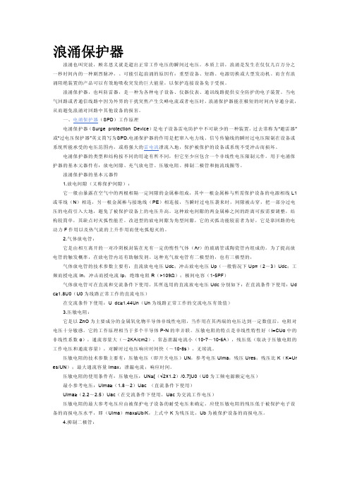
一、浪涌保护器的工作原理浪涌保护器通常被称为突波,或是防雷器,简称为SPD,主要是保护电子设备免受“浪涌”的损害。
浪涌保护器可用于民用建筑电路中的限制瞬时过电压和泄放电涌电流,能有效防止由于雷电、短路、电源切换等原因产生的过电压的潜在危险。
浪涌保护器主要是选用压敏电阻器、充气放电管、扼流电圈等限制电压的元件,限制突然进入电路中的过电压,使得电路电压低于线路所能承受的最高值,同时将由雷电或其他系统因素产生的强电流导入地面,释放多余的能量。
二、浪涌保护器在防雷设计中的应用1、浪涌保护器的发展国外早在上世纪五、六十年代,就已经在防雷设计中广泛使用了浪涌保护器,在国外也被称为浪涌流保护器。
我国的浪涌保护器最早称为电压保护器,但实际上浪涌保护器不仅能够抑制过电压,还能分走浪涌电流,所以将这种避雷器简单的称作过电压保护器并不全面,因而在对《建筑物防雷设计规范》(GB50057)标准进行局部修订时,就将其统一称为浪涌保护器。
随着近年来我国经济的快速发展和科学技术水平的不断提高,人们的防雷意识不断增强,使得国内的浪涌保护器也有了很快的发展,并且逐渐形成了一个新的产业。
目前,浪涌保护器可以按照不同的分类方法分成不同的类型,其中按工作原理分类,可以分为电压开关型、限压型和组合型浪涌保护器;按照其用途可以分为电源线路浪涌保护器和信号线路浪涌保护器两种;按组合的结构可以分为间隙类、放电管类、压敏电阻类、抑制二极管类、压敏电阻/气体放电管组合类和碳化硅类;按照安装的形式可以分为并联浪涌保护器和串联式浪涌保护器。
加油站浪涌保护器使用要求

提高设备稳定性
通过减少浪涌对设备的影 响,降低设备误动作率, 提高设备运行稳定性。
延长设备使用寿命
减少浪涌冲击对设备的损 害,延缓设备老化过程, 从而延长设备使用寿命。
03 浪涌保护器选型与安装要 求
选型依据及建议
根据加油站电力系统的额定电压、负载电流、短路容量等参数,选择浪 涌保护器的额定电压、最大持续工作电压和最大放电电流等关键指标。
浪涌保护器成功抵御多次雷电冲击, 保障加油站设备安全运行,减少维修 成本,提高运营效率。
浪涌保护器选型与配置
根据加油站实际情况,选用高性能浪 涌保护器,并进行合理配置,确保全 面覆盖加油站关键设备。
案例二:问题解决方案分享
问题描述
某加油站曾遭遇雷电袭击,导致 部分设备损坏,影响正常运营。
原因分析
经过调查,发现原有浪涌保护器 性能不足,无法有效抵御强雷电
浪涌对加油站设备影响
浪涌电压可能导致加 油站设备损坏,如击 穿绝缘层、烧毁电路 板等。
长期浪涌冲击会加速 设备老化,缩短使用 寿命。
浪涌电流可能引发设 备误动作,如加油机 乱码、液位仪数据异 常等。
需求分析:为何需要使用浪涌保护器
01
02
03
保护设备安全
浪涌保护器可以有效吸收 和抑制浪涌电压和电流, 保护加油站设备免受损坏。
针对加油站特殊环境设计,具 有防爆、防雷击、防静电等特
点,确保加油站安全运营。
02 加油站电气系统特点与需 求分析
加油站电气系统概述
加油站电气系统主要包括供配电系统、照明系统、防雷接地系统以及弱电系统等。
供配电系统通常采用TN-S接地方式,以确保用电安全。
加油站内设备众多,包括加油机、液位仪、潜油泵等,对电气系统的稳定性和可靠 性要求较高。
JL 系列电动机保护器 说明书
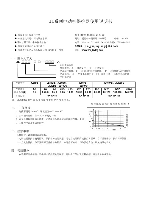
JL系列电动机保护器使用说明书 ● 国家火炬计划项目产品 厦门佳兴电器有限公司 ● 专家鉴定结论:国内领先水平 地址:厦门市枋湖西路52-58号 邮编:361009 ●国家专利产品、中外技术结晶 电话:0592 - 5773829、5620743 传真:0592-5620742 ● 国家节能机电产品推广项目 E-MAIL :jim_yanjingtang@ ● 福建省工业产品执行标准证书 Q/XJX 01-2001 网址: 一、型号及含义 A 和160 – 三相电机保护器 产品型号 JL30FB JL30DB 、JL30DC 、 JL10DB 、JL10DC JL80FB 、JL80FC JL160FB 、JL160FC产品规格 5A 3A 6A 25A 30A 30A 80A 80A 120A 160A 200A 电流范围(A) 2-5 0.25-3 0.5-6 3-25 10-3010-30 20-80 20-8060-120100-160140-200外形尺寸 73×46×8590×49×89120×55×109注:JL30FB需配电流比互感器用于保护大功率电机。
反时限过载保护特性曲线如图2 二、 工作环境: 1.海拔不超过2000米,环境温度-40℃—+85℃. 2.大气相对湿度:在+40℃时不超过85%. 4.无剧烈冲击和振动的地方. 三、注意事项 1.使用前,请详细阅读说明书。
2.定期检查保护器使用情况。
保护器如出现问题,请与当地经销商或我公司联系。
自行拆开维修,我公司不保修。
3.一旦发生保护,必须查明原因并排除故障后,方可重新启动。
切勿强行启动,以免烧毁电动机。
四、售后服务 在不撕开防伪标签、不损坏产品外观的情况下,两年内产品出现质量问题,可免费维修或更换。
五、安装及调试: 1.JL10DB☆ 刻度面板说明 ① 电流整定旋钮 ② 绿灯:电源指示灯 ③ 红灯:过电流指示灯 ④ 动作时间整定旋钮 ☆ 调试说明 ⑴ 根据电动机实际工作电流选择一只合适规格的保护器。
JLSP系列电涌保护器

使用范围广:可以应用于不同的配电方式中(TT或TN模式);通流容量范围大:100KA-200KA/相;使用寿命长:经受C3类(8/20μs,10KA)脉冲1000次冲击无损坏;工作频率:40-60HZ;温度范围:-40-85℃;失效检测指示;内置热断路器和保险丝;高强度阻燃塑料外壳;02:电源浪涌是电路中持续约百万分之一秒的瞬态过电压。
比如系统工作电压为380V的马达可通过几千伏的绝缘测试,而一个在电路板上工作电压为5V的芯片不可能有与马达相同的绝缘强度。
电源浪涌保护器是一个复杂的产品,它不仅仅是一个电气部件,它是将不同功能的部件精密地组合在一个电路中,以最短的时间(纳秒级)内将被保护线路接入等电压系统中,使设备各端口等电位,同时释放在电路上因雷击而产生的大量脉冲能量,将其短路泄放到大地,降低设备各端口的电位差。
该系列产品可以极其有效地抑制由雷电引起的感应过电压及系统操作过电压,保护设备安全,保障系统的正常运行;1. 适用范围主要适用于配电室、配电柜、和其它重要场所总电源,移动通信基站,微波通信局/站,电信机房,工厂,民航,金融,证券等系统的主电源防护;2. 所替代的产品取代了火花间隙、压敏电阻、抑制二极管等保护元件;3. 性能特点:3.1 易辨识的状态显示可以方便维护人员了解浪涌保护器的工作状态,易维护3.2 35mm的标准导轨式安装;3.3 浪涌识别技术:在模块内装入识别开关,此开关可以识别浪涌,正常工作时处于常开状态,仅在出现浪涌的5ns闭合。
此开关可以防止漏流,延缓元件老化,提高产品寿命;3.4 独特的热备份保护功能:在雷击电流过大造成产品击穿后,产品会出现红色脱扣警示,并且投入备份阀片工作,在保护器没及时更换时,还具备同等的防护功能。
此功能是根据我们多年来的经验研发而成,对防护频繁的操作过电压和雷电感应过电压有巨大和深远的意义;3.5 采用分级防雷的理念:例如系统工作电压为380V的马达可通过几千伏的绝缘测试,而一个在电路板上工作电压为5V的芯片不可能有与马达相同的绝缘强度。
浪涌保护器(SPD)的选择和使用

L2,L4 L2,L4
S2
D3 D1 D2 D3
D3
L1a,L2,L4 L1 ,L4a L1,L2,L3,L4 L1a,L2,L4
L1a,L2,L4
S3
D2 D3 D3
L2,L4 L2,L4 L2,L4
S4
根据雷击点位置划分的损害来源 损害类型 D1:接触和跨步电压导致的人员伤亡(人 和牲畜); D2:实体损害; D3:过电压导致的电气和电子系统的失效。 损失类型 L1:生命损失; L2:向大众服务的公共设施的损失; L3:文化遗产损失; L4:经济损失。
SPD 定义
电涌保护器——目的在于限制瞬态过电压和分走电涌
电流的器件,它至少含有一非线性元
件。
电源SPD——连接到低压配电系统的SPD。 电信SPD——连接到电信和信号网络的SPD。 适用电压:直流1500V 交流1000V(r· m· s)(50Hz)
低压配电系统用 SPD 分类
T1(I级分类试验) 用标称放电电流In、1.2/50μs冲击电压和10/350 μs冲击电流Iimp做的试验,对应为电压开关型 SPD T2(Ⅱ级分类试验) 用标称放电电流In、 1.2/50μs冲击电压和8/20 μs最大放电电流Imax做的试验,对应为限压型 SPD。 T3(Ⅲ级分类试验) 用混合波( 1.2/50μs和8/20 μs)做的试验,对 应为组合型SPD。
综合防雷系统
雷电防护系统 外部防雷 内部防雷
接 闪 器
引 下 线
接 地 装 置
屏 蔽 ( 法 拉 弟 笼 )
等 电 位 连 接
防 闪 络 措 施
电 涌 保 护 器
相关标准
GB 50174-2008 电子信息系统机房设计规范
浪涌保护器使用原则资料讲解

浪涌保护器使用原则电涌保护器的性能要求和使用原则引言SPD(Surge Protective Device)是国际电工委员会(IEC)标准中对电涌保护器的英文缩写。
过去国内大多数生产厂商使用避雷器、低压避雷器、电子防雷器等名称均不够准确,使用避雷器一词易与使用于高压供电系统的避雷器相混淆,特别是国家标准已颁布了避雷器的内容和设有专门的检测单位,它们主要应用于高压系统。
行业标准GA173把SPD定名为防雷保安器是与国家制定电器安全标准的规定相矛盾的,该标准对使用“安全”一词有特定规定,不允许把“安全”及类似含意的词与某元件联用,而且SPD除具备有防雷的功能外,还有抑制投切过电压的作用。
在IEC61312、IEC61643和IEC60364等相关标准中对SPD性能和安装使用提出了一系列要求,简要归纳出要点,以供讨论。
一、SPD的定义:在GB50057-94《建筑物防雷设计规范》中,SPD定名是过电压保护器:“用以限制存在于某两物体之间的冲击过电压的一种设备,如放电间隙,避雷器或半导体器具”。
近日标准起草人林维勇先生在为中国气象局组织起草的某标准草案讨论稿上郑重的将“过电压保护器”易名为“电涌保护器”,并以近期颁布的国际标准和美国标准做了更名的文字说明。
SPD的定义应是,电涌保护器(SPD):用以限制瞬态过电压和引导电涌电流的一种器具,它至少应包括一种非线性元件。
这一观点将在林维勇先生执笔对GB50057-94局部修订条文征求意见稿中做为强制性国家标准出现。
二、SPD的分类:SPD可按几种不同方法进行分类:1.按使用非线性元件的特性分类:(设计电路拓朴)电压开关型SPD :当没有浪涌出现时,SPD 呈高阻状态;当冲击电压达到一定值时(即达到火花放电电压),SPD 的电阻突然下降变为低值。
常用的非线性元件有放电间隙,气体放电管等。
开关型SPD 具有大通流容量(标称通流电流和最大通流电流)的特点,特别适用于易遭受直接雷击部位的雷电过电压保护。
浪涌保护器使用说明书

᱂ܝ⇨ϴЏԧᓔথഄ☦▊ṗᎹ࣏☿⇨☿⇨᪂᪂07/⌾⍠⌾⍠ֱᡸ఼ֱᡸ఼ֱᡸ఼ՓϬՓϬՓϬ᪸ᯢк᪸ᯢк᮴⏥᮴⏥ṙᗱᅝṙᗱᅝṙᗱᅝᅝܼᅝܼᅝܼ᪂᪂᪂᳝└᳝└᳝└݀ৌ݀ৌT h e S L P S e r i e s is a range of surge protec-tion devices combining high packing densi-ties, application versatility, proven hybrid cir-cuitry and simple installation -- features which make the series the most cost effec-tive surge protection solution for process control equipment systems and communica-tions networks.T h e m u l t i -s t a g e h y b r i d s u r g e p r o t e c t i o n n e t -w o r k at the heart of the SLP uses a combi-nation of solid state electronics and a gas filled discharge tube (GDT) to provide surge protection up to 20kA. This impressive surge protection circuit is designed to exhibit exceptionally low line resistance and adds only a tiny voltage drop to the circuit.I n o p e r a t i o n , t h e S L P d e v i c e d o e s n o t a d v e r s e l y a f f e c t t h e p e r f o r m a n c e o r o p e r a -t i o n o f t h e l o o p or combined equipment. The device allows signals to pass with very little attenuation while diverting surge currents safely to ground and clamping output volt-ages to safe levels.F u l l y a u t o m a t i c i n o p e r a t i o n ,SLP devicesreact immediately to make sure thatequipment is never exposed to damagingsurges between lines or the lines andground. Reacting instantaneously, the SLPredirects surges safely to ground andthen resets automatically.T h e v e r s a t i l e S L P s e r i e s d e s i g n c o n s i d e r st h e n e e d f o r h i g h p a c k i n g d e n s i t i e s andhas a product combining protection fortwo process loops into one case. Eachmodule provides full hybrid surge protec-tion for two process loops.F o r h i g h e r b a n d w i d t h a p p l i c a t i o n s ,the SLPseries has been developed to meet thedemands of today’s highest speed com-munication systems.O n e s i m p l e m a n u a l o p e r a -t i o n clamps modulessecurely onto D I Nrail, which auto-matically provides the essential high-integrity ground connection.A 10 Y e a r ‘N o F u s s ’ w a r r a n t y is available as standard for the SLP so if a correctly connected device should fail for any rea-son, simply return it for a free replace-ment.‘T o p -h a t ’ (T -s e c t i o n ) D I N r a i l is generally suitable for mounting SLP modules although for adverse environments, a spe-cially-plated version is available from MTL Surge Technologies.Data & SignalProtectionUltra-slim user-friendly devices for protecting electronic equipment and systems against surges on signal and I/O cabling.G S u r g e p r o t e c t i o n f o r t w o l o o p s p e r S L P (o r o n e 4-w i r e c i r c u i t )G P l u g c o n n e c t o r s f o r q u i c k a n d e a s y c o n n e c t i o n o r r e w i r i n gG S p a c e -s a v i n g d e s i g n , 6m m w i d t h p e r l o o pG M u l t i -s t a g e h y b r i d p r o t e c t i o n c i r c u i t r y - 20k A m a x i m u m s u r g e c u r r e n tG R a n g e o f v o l t a g e r a t i n g s - t o s u i t a l l p r o c e s s I /O a p p l i c a t i o n sG D e s i g n e d f o r h i g h b a n d w i d t h , l o w r e s i s t a n c e a p p l i c a t i o n sSLP SeriesS p e c i f i c a t i o n All figures typical at 77°F (25°C) unless otherwise statedM a x i m u m s u r g e c u r r e n t 20kA (8/20μs waveform) per line L e a k a g e C u r r e n t <1μA @ working voltage M a x i m u m r a t e d l o a d c u r r e n t1.50A L o o p r e s i s t a n c e 2 OhmC a p a c i t a n c eLine - Line - 60pFB a n d w i d t h-1db @9kHz - 37MHz-3dB @50MHzR e s p o n s e t i m e<1nsA m b i e n t t e m p e r a t u r e–40°F to +176°F (working)–40°C to +80°C (working)–40°F to +176°F (storage)–40°C to +80°C (storage)H u m i d i t y5 to 95% RH (non-condensing)T e r m i n a l s12 AWG (2.5mm 2)E l e c t r i c a l c o n n e c t i o n sPlug/header screw terminal strip M o u n t i n gT-section DIN-rail(35 x 15mm rail)W e i g h t5oz (140g approximately)Case flammabilityUL94 V-2E M C c o m p l i a n c eBS EN 60950:1992BS EN 61000-6-2:1999BS EN 61010-1:1993E l e c t r i c a l s a f e t yUL Isolated Loop Protector (Pending)Class I, Division 2, Groups A, B, C & Dhazardous locations (Pending)T o o r d e r s p e c i f y - Order by module, as listed in the specifi-cation table.Note: I n accordance with our policy of continuous improvement,we reserve the right to change the product’s specification withoutnotice.2 Installation Connection detailsR e vA09/16/04S t a n d a r d C e r t i f i c a t e /A p p r o v e d f o r P r。
西泰尔光伏系统浪涌保护器使用说明书

SURGE PROTECTORSFORPhotovoltaic systemswww.citel.fr1221ROOF TOP INSTALLATIONSA professional approach to lightning and surge protection will guarantee your photovoltaic systems a long lifeSPD locationThe diagram below shows the pertinent locations for surge protectors as described in the CLC/TS61643-12 guide.Additional Surge ProtectorsIf the equipment to be protected (inverter or PV modules) is located more than 10 meters away from the initial surge protec-tor, the guide imposes the insertion of a complimentary surge protector to improve the level of protection.For low power PV applications, i.e. residences and small offices, it is necessary to consider surge protecting the AC output of the Inverter that connects directly into the electric power grid as well as the DC input side of the Inverter fed by the PV modules.AC Surge Protectorto protect all loads connected to the facility’s main distribution pa-nel against transients originating from the AC utility grid.AC networkAdditional AC Surge protectorIf the length of conductor between the PVinverter and the primary SPD in the main board exceeds 10 m, an additional SPD is necessary at the input of the inverter .Type 2 surge protectorDepending on the lightning rating of the installation area, a Type 2 surge protector on the DC network may be required.PV network AC network1222121121INDUSTRIAL AND PUBLIC BUILDINGSType 2 surge protectorIf the building is not equipped with a lightning rod system then a Type 2 surge protector is necessary or compulsory on the AC and DC inputs of the inverter . On the PV side, for cable lengths greater than 10 meters it is mandatory to install additional surge protectors at each end of the cable run.Type 1 surge protectorIf the installation is equipped with lightning rod systems, Type 1 surge protectors are compulsory at the AC input.The same on the DC side, Type 1 surge protectors are compul-sory in case of not isolated ligtning rod installation. Depending on the level of protection of the lightning rod, the total discharge current (Itotal) required can reach 20 kA.(See guide CLC / TS50539-12).Medium to large power PV systems can be installed on industrial and service facilities.In order to avoid very costly downtime and lost productivity resulting from a direct or indirect lightning strike, it is critical, and in some cases mandatory, to install surge protection at key points within your facility and its vital power and communication networks.AC networkType 2 AC surge protectorWhen the local lightning density is Ng > 2.5, by standard, it is mandatory to install an AC surge protector at the incoming service of the three phase network. In areas with a lower lightning density, while it is not mandatory, it is certainly good practice to install a surge protector for protection against switching transients originating from the external power grid not associated with lightning.Dataline Surge ProtectorsFor inverters connected to data networks(monitoring, control) or probes (luminous flux, temperature...), installation of relevant surge protectors is highly recommended.PV networkAC networkDatalinesAdditional AC Surge ProtectorDue to the long length of strings de-ployment, additional surge protectors are required near the PV modules. Installed generally in connection boxes.PV networkType 2 surge protectorDepending on the level of lightning strike in the installation area, a Type 2 SPD on the DC network at the in-verter input may be required. In the presence of non-isolated lightning rod, a Type 1 SPD is required.If the length of conductor between the PV inverter and the arrester in the MLVS ex-ceeds 10 m, an additional SPD is neces-sary at the input of the inverter.11111212PV POWER PLANTSType 1 surge protectorIf the PV field is equipped with lightning rod systems (rods, open air wiring…) Type 1 surge protectors are compulsory at the AC input.On the DC side, Type 1 surge protectors are compulsory at the inverters DC output as defined by CLC/TS 50539-12. Due to the long lengths of cabling required to connect numerous strings running throughout the PV farm, additional surge protectors are required at the input of the PV modules as well.PV power plants present a high risk of direct lightning impact and surges due to the large exposed area and the long lengths of the electric conductors.In order to avoid problems leading to costly damage and downtime, it is compulsory to install surge protectors at key points in the PV system.Type 1 DC Surge Protector panelDue to the long length of wires (>> 10 m), additional Type 1 SPDs are required at the input of PV modules. They are usually instal-led inside combiner boxes.AC Surge ProtectorType 1 surge protector is required at the AC network entrance whenever a light-ning rod is installed on the premises.Dataline Surge ProtectorsFor inverters connected to data networks (monitoring, control) or probes (luminous flux, temperature...), installation of relevant surge protectors is highly recommended.Type 1 DC Surge ProtectorDue to the risk of direct lightning strikes, Type 1 surge protector must be applied.AC network DatalinesPV networkPV networkDS60VGPV-1500G/51DS50PV-800G/51DLA-24D3DAC1-13-31-275 DAC40C-31-275DAC50-11-275 DAC40C-11-275DDC30C-20-65Head office FranceTél. : +33 1 41 23 50 23 e-mail:**************** Web : www.citel.fr FactoryReimsTél. : +33 3 26 85 74 00 e-mail:**************** Germany BochumTél. : +49 234 54 72 10 e-mail:************* Web : www.citel.deUSAMiramarTel : (954) 430 6310e-mail:*************Web site : ChinaSales departmentShanghaiTél. : +86 21 58 12 25 25e-mail:****************Web : FactoryTél. : +86 21 58 12 80 67RussiaMoscouTél. : +7 499 391 47 64e-mail:*************Web : www.citel.ruIndiaNew DelhiTél. : +91 11 2626 12 38e-mail:********************Web : www.citel.inThailandBangkokTél. : +66 (0) 2 104 9214Web : www.citel.frCITEL range DAC1-13DAC50DAC40C3-phaseDAC40C1-phase Surge protector Type 1+2Type 2Type 2Type 2AC network Un230 Vac230 Vac230 Vac230 Vac Max. AC operating voltage Uc255 Vac255 Vac255 Vac255 Vac Nom. discharge current (8/20µs)In20 kA20 kA20 kA20 kAMax. discharge current (8/20µs)Imax50 kA50 kA40 kA40 kAMax. lightning current (10/350µs)Iimp12.5 kA---Protection level Up 1.5/1.3 kV* 1.5/1.25 kV* 1.5/1.25 kV* 1.5/1.25 kV*P/N for single phase network DAC1-13-11-275DAC50-11-275-DAC40C-11-275 P/N for 3L+N network DAC1-13-31-275DAC50-31-275DAC40C-31-275-Télésignalisation de déconnexion OptionDAC1-13S-xx-xxxOptionDAC50S-xx-xxxOptionDAC40CS-xx-xxxOptionDAC40CS-xx-xxxDAC1-13 DAC50 DAC40C Type 1 and Type 2 Surge Protectors for AC power supply IEC61643-11 complianceDC SURGE PROTECTORS FOR PV OFF-GRID SITECITEL model DDC30C-20-65DDC40C-20-100DDC40C-20-180DDC40C-20-275DDC40C-20-460Network48 Vdc75 Vdc130 Vdc220 Vdc350 VdcMax.operating voltage Uc65 Vdc100 Vdc180 Vdc275 Vdc460 VdcNominal dischargecurrent (8/20µs)In15 kA20 kA20 kA20 kA20 kAProtection level Up300 V390 V620 V900 V1400 vRemote signalling OptionDDC30CS-20-65OptionDDC40CS-20-100OptionDDC40CS-20-180OptionDDC40CS-20-275OptionDDC40CS-20-460DDC30CDDC40C Type 2 Pluggable Surge Protector for PV Off-grid site- *) Common mode (L/PE or N/PE)/Differential mode (L/N)- Specific version DAC1-13VG and DAC50VG available: suppression of operating and leakage currents. SURGE PROTECTORS FOR AC NETWORK。
浪涌保护器说明书-柏为为

60kA (8/20μs)
100kA (8/20μs) 2.5kV ≤25ns
PA6 UL94 V-0 IP20
L/N - PE
1.5kV ≤100ns
N - PE
视窗显示红色时表示产品已失效,需更换!
/
1P、2P、3P、4P、1P+N、3P+N
浮动切换触点
250VAC/0.1A 125VDC/0.2A 75VDC/0.5A
浮动切换触点
250VAC/0.1A 125VDC/0.2A 75VDC/0.5A
ARU2-20 型 SPD 技术参数: 型号规格
电气参数 交流标称电压 N
最大持续工作电压 Uc 标称放电电流 In
最大放电电流 Imax 电压保护水平 Up(at In)
响应时间 外壳材质 外壳防护等级 保护模式
工作指示
交流标称电压 UN 最大持续工作电压 Uc
标称放电电流 In 冲击电流 Iimp 电压保护水平 Up(at In)
响应时间 外壳材质 外壳防护等级 保护模式
工作指示
SPD 组合方式
遥信触点类型
遥信接点最大值
ARU1-15
NPE 极(若有)
220/380V 385Vac
50kA (8/20μs) 15kA (10/350μs) 2.5kV ≤25ns
目录
1 产品概述..................................................................................................................................... 4 2 执行标准..................................................................................................................................... 4 3 产品特点..................................................................................................................................... 4 4 型号命名..................................................................................................................................... 4 5 正常工作条件............................................................................................................................... 4 6 技术参数与外形........................................................................................................................... 5 7 产品外形..................................................................................................................................... 9 8 接线方式................................................................................................................................... 11 9 安装及维护............................................................................................................................... 13 附录一............................................................................................................................................. 13
SP1 浪涌保护器安装和操作说明书

1.0 IntroductionThis manual describes how to install a Surge Protective Device (SPD) in parallel (shunt) across the AC supply of the following types of electrical systems: •Split Phase•Three-Phase Wye •Three-Phase DeltaThe SPD is designed to be installed on service entrance, branch panels, and/or individualequipment disconnects, and functions to protect sensitive electronic equipment from damaging voltage transients. The connecting wires do not carry supply current. Instead, they carry only short- d uration currents that are associated with a transient event.These instructions do not cover all details, variations, or combinations of the equipment, its storage, delivery, installation, checkout, safe operation, or maintenance. If you require further information regarding a particular application or installation that is not covered in this manual, please contact Eaton’s Power Quality Technical Support at 1-800-809-2772, option 4, option 2.1.1 Safety PrecautionsA licensed/qualified electrician must complete all instructions described in this manual in accordance with the U.S. National Electrical Code, state and local codes, or other applicable country codes. All electrical codes supersede these instructions.Suitable For Use on a Circuit Capable of Deliv-ering Not More Than 200,000 rms symmetrical Amperes. Convient Aux Circuits Non Suscep-tibles De Delivrer Plus De 200,000 Amperes symetriques Eff.Improper installation can cause death,injury and/or equipment damage. Follow all warnings and cautions. Completely read and understand the information in this instruction manual before attempting to install or operate this equipment.Improper wiring could cause death, injury, and/or equipment damage. Only licensed/qualified electricians who are trained in theinstallation and service of electrical devices are to install and service this e appropriate safety precautions and equipment for arc flash protection.During normal operation, hazardous volt-ages are present inside the SPD.When servicing the SPD, follow all safe work practices to avoid electrical shock.Warning No Serviceable PartsAvertissement: Aucune piece remplacable ou reparableDo not perform a high-pot test with the SPDc onnected to the electrical system.Failure to disconnect the SPD during a high-pot test will result in damage to the SPD.1.2 Catalog Numbering SystemVoltage Code 240S = 120/240V single split-phase (3W)208Y = 120/208 wye (4W+G)480Y = 277/480 wye (4W+G)600Y = 347/600Y wye (4W+G)600D = 600 delta (3W+G)Series SP1-240D = 240 delta (3W+G)480D = 480 delta (3W+G)Figure 2-2. Conduit Installation2.1.2 Wall MountingMount the SPD directly on a wall using the SPD’s optional SP1MNTGKIT as follows:1. Screw the wall bracket to the wall or other mounting surface using two #10 screws of the appropriate type (not provided) with the large hole in the bracket at the top.2. Thread the lead wires from the SPD through the large hole and insert the integrated hub into the large hole with the hub pointed upwards. 3. Use the locknut (provided) to secure the SPD hub to the bracket.2.1.3 For DIN rail mountingMount the SPD directly on DIN rail using the SPD’s optional SP1MNTGKIT as follows:1. Snap the DIN rail clip into the two smallest holes in the mounting bracket.2. Thread the lead wires from the SPD through the large hole in the bracket and insert the integrated hub into the large hole.3. Use the locknut (provided) to secure the SPD hub to the bracket.4. Snap the SPD and bracket to the DIN rail (not provided) with the hub pointed upwards.Figure 2-3. Wall Mounting or DIN Mounting withOptional SP1MNTGKIT2.0 InstallationRefer to Section 1.2 and look at the label on the SPD to verify that the SPD’s voltage rating and wiring configuration matches that of the electri -cal system. Use an AC voltmeter to measure the system’s line voltage to ensure that the correct model of SPD is being installed. Damage to the SPD may result if it is connected to an electrical system of a higher voltage or different wiring configuration.2.1 MountingThe SPD can be mounted directly to theelectrical panel, or to a wall or din-rail with the addition of an optional mounting kit, Catalog number SP1DINRAILKIT.IMPORTANT!• Choose a mounting location for the SPD that provides the shortest and straightest pos-sible wiring (lead length) from the SPD to the electrical system connections. Excessive lead length and sharp bends will degrade SPD performance.• If the electrical system uses an isolatedground , the SPD must be isolated from ground using insulated conduit fi ttings.• When using conduit, avoid using 90° elbows and keep the conduit run as short and straight as possible.2.1.1 Conduit InstallationMount the SPD directly to the electrical panel using a 1/2” locknut as shown in Figure 2-1.When mounting the SPD outdoors, use weath-erproof conduit and fittings to maintain the enclosure’s NEMA 4 rating. See Figure 2-2.Figure 2-1. 1/2" Locknut Mountingin conduit and longer than necessary wire Keep conduit length C V X 050CVX050C V X 050CVX0502.2 WiringIMPORTANT!• Be sure to follow all national, state, and local elec-trical codes when making wiring connections.• When connecting the wires from the SPD to the electrical system, cut the wires as neces-sary to keep them as short as possible.• To maximize the SPD’s performance, twist and bind the wires together to reduce the impedance of the wire (one twist/inch).• If the system utilizes an isolated ground, the SPD’s ground wire must be connected to the system’s isolated ground bus.1. Locate the electrical system’s applicable wiringdiagram in Section 2.3. Reference this wiringdiagram as necessary in Steps 2, 3, and 4. 2. Connect the SPD’s ground wire (green) to thesystem’s ground connection. Delta only.3. Connect the SPD’s neutral wire (white) to thesystem’s neutral connection (not required for 3-phase delta systems – 240D, 480D, and600D).4. Connect the SPD’s phase A, B, and Cwires (black) to the system’s corresponding phase A, B, and C connections accord-ing to a pplicable national, state, and localelectrical codes.3-Phase Wye (208Y, 480Y)600YSplit Phase(240S)3-Phase Delta (240D, 480D)600D3.0 Operation3.1 Power Up and System Checkout Apply system power. The LED should light.If the connected LED does not light, remove power, check connections, and test again. If the LED still does not light, contact your sup-plier.3.2 Routine OperationAfter system power has been applied, the SPD automatically begins to protect down-stream elec-trical devices from damaging voltage transients. With all phase voltages present, the LED indica-tor reports the status of the protection elements and is active when all of them are intact and providing protection. Any loss of protection is signaled when the LED extinguishes.The device is not repairable and contains no user serviceable parts. If the unit fails, as evi-denced by the LED turning OFF, the unit must be replaced. Please contact your distributor as the SPD may be under warranty.DO NOT use the Suppression Circuit Status LEDs as an indication of the presence or ab-sence of system phase voltages.2.3 SPD Wiring Diagrams4.0 SpecificationsDescriptionRatingsSurge current capacity per phase 50kANominal Discharge Current (In)20kA for SP1-240S, 208Y, 480Y, 240D, and 480D, 10kA for SP1-600Y and 600D Short circuit current rating (SCCR)200kASPD typeType 1 (can also be used in Type 2 applications)System voltages available (VAC) Single split-phase Three-phase wye Three-phase delta 120/240 120/208, 277/480, 347/600 240, 480, 600Protection modesSingle split-phase and three-phase wye Three-phase delta L-N, L-L L-G, L-L Maximum continuous operating voltage (MCOV) SP1-240S and SP1-208Y 150 L-N, 300 L-L SP1-480Y 320 L-N, 640 L-G SP1-600Y 420 L-N, 840 L-G SP1-240D 300 L-G, 300 L-L SP1-480D 640 L-G, 640 L-L SP1-600D 840 L-G, 840 L-L Input power frequency 50/60 Hz Enclosure rating NEMA 4Operating temperature -20°C through 50°C (-4°F through 122°F)Operating humidity 5% through 95%, noncondensing Operating altitude Up to 16,000 ft (5000m)Agency certification and approvalsUL1449 4th Edition Type 1 and Type 2 SPDCSA-22.2 No. 269.1-17 2nd EditionWarranty 2 years UL 96A Compliant Yes NFPA 780 Compliant Yes Wire Length and AWG Factory prewired with 24 inches of 12 AWG wireto give any advice or recommendations by Eaton shall not constitute any warranty by or impose any liability upon Eaton. The foregoing constitutes the sole and exclusive liability of Eaton AND IS IN LIEU OF ANY AND ALL OTHER WARRAN-TIES EXPRESSED, IMPLIED OR STATUTORY AS TO THE MERCHANTABILITY, FITNESS FOR PURPOSE SOLD, DESCRIPTION, QUALITY, PRODUCTIVENESS OR ANY OTHER MATTER. In no event shall Eaton be liable for special or con-sequential damages or for delay in performance of the warranty. This warranty does not apply if the product has been misused, abused, altered, tampered with, or used in applications other than specified on the nameplate. At the end of the war -ranty period, Eaton shall be under no further war-ranty obligation expressed or implied. The product covered by this warranty certificate can only be repaired or replaced by the factory. For help on troubleshooting the SPD, or for warranty informa-tion, call 1-800-809-2772, Option 4, sub-option 2. Repair or replacement units will be returned col-lect. If Eaton finds the return to be a manufacturer’s defect, the product will be returned prepaid.Eaton1000 Cherrington ParkwayMoon Township, PA 15108-44312USAFor Technical Support please call: 1-800-809-2772© EatonAll Rights Reserved5.0 WarrantyEaton warrants these products for a period of 2 years from the date of delivery to the purchaser to be free from defects in both workmanship and materials. Eaton assumes no risk or liability for results of the use of the products purchased from it, including but without limiting the generality of the foregoing: (1) The use in combination with any electrical or electronic components, circuits, systems, assemblies, or any other materials or substances; (2) Unsuitability of any product for use in any circuit or assembly. Purchaser’s rights under the warranty shall consist solely of requiring Eaton to repair, or at Eaton’s sole discretion, replace, free of charge, F.O.B. factory, and defective items re-ceived at said factory within said term determined by Eaton to be defective. The giving of or failure。
浪涌保护器

浪涌保护器一、什么是浪涌保护器?浪涌保护器(电涌保护器)又称避雷器,简称(SPD)适用于交流50/60HZ,额定电压至380V的供电系统(或通信系统)中,对间接雷电和直接雷电影响或其他瞬时过压的电涌进行保护,适用于家庭住宅、第三产业以及工业领域电涌保护的要求,具有相对相,相对地,相对中线,中线对地及其组合等保护模式。
浪涌也叫突波,顾名思义就是超出正常工作电压的瞬间过电压。
本质上讲,浪涌是发生在仅仅几百万分之一秒时间内的一种剧烈脉冲,可能引起浪涌的原因有:重型设备、短路、电源切换或大型发动机。
而2 浪涌保护器的分类SPD是电子设备雷电防护中不可缺少的一种装置,其作用是把窜入电力线、信号传输线的瞬时过电压限制在设备或系统所能承受的电压范围内,或将强大的雷电流泄流入地,保护被保护的设备或系统不受冲击。
2. 1 按工作原理分类按其工作原理分类,SPD可以分为电压开关型、限压型及组合型。
⑴电压开关型SPD。
在没有瞬时过电压时呈现高阻抗,一旦响应雷电瞬时过电压,其阻抗就突变为低阻抗,允许雷电流通过,也被称为“短路开关型SPD”。
⑵限压型SPD。
当没有瞬时过电压时,为高阻抗,但随电涌电流和电压的增加,其阻抗会不断减小,其电流电压特性为强烈非线性,有时被称为“钳压型SPD”。
⑶组合型SPD。
由电压开关型组件和限压型组件组合而成,可以显示为电压开关型或限压型或两者兼有的特性,这决定于所加电压的特性。
分级防护:第一级防雷器可以对于直接雷击电流进行泄放,或者当电源传输线路遭受直接雷击时传导的巨大能量进行泄放,对于有可能发生直接雷击的地方,必须进行CLASS—I的防雷。
第二级防雷器是针对前级防雷器的残余电压以及区内感应雷击的防护设备,对于前级发生较大雷击能量吸收时,仍有一部分对设备或第三级防雷器而言是相当巨大的能量会传导过来,需要第二级防雷器进一步吸收。
同时,经过第一级防雷器的传输线路也会感应雷击电磁脉冲辐射LEMP,当线路足够长感应雷的能量就变得足够大,需要第二级防雷器进一步对雷击能量实施泄放。
浪涌保护器
浪涌保护器浪涌也叫突波,顾名思义就是超出正常工作电压的瞬间过电压。
本质上讲,浪涌是发生在仅仅几百万分之一秒时间内的一种剧烈脉冲,。
可能引起浪涌的原因有:重型设备、短路、电源切换或大型发动机。
而含有浪涌阻绝装置的产品可以有效地吸收突发的巨大能量,以保护连接设备免于受损。
浪涌保护器,也叫防雷器,是一种为各种电子设备、仪器仪表、通讯线路提供安全防护的电子装置。
当电气回路或者通信线路中因为外界的干扰突然产生尖峰电流或者电压时,浪涌保护器能在极短的时间内导通分流,从而避免浪涌对回路中其他设备的损害。
一、电涌保护器(SPD)工作原理电涌保护器(Surge protection Device)是电子设备雷电防护中不可缺少的一种装置,过去常称为“避雷器”或“过电压保护器”英文简写为SPD.电涌保护器的作用是把窜入电力线、信号传输线的瞬时过电压限制在设备或系统所能承受的电压范围内,或将强大的雷电流泄流入地,保护被保护的设备或系统不受冲击而损坏。
电涌保护器的类型和结构按不同的用途有所不同,但它至少应包含一个非线性电压限制元件。
用于电涌保护器的基本元器件有:放电间隙、充气放电管、压敏电阻、抑制二极管和扼流线圈等。
浪涌保护器的基本元器件1.放电间隙(又称保护间隙):它一般由暴露在空气中的两根相隔一定间隙的金属棒组成,其中一根金属棒与所需保护设备的电源相线L1或零线(N)相连,另一根金属棒与接地线(PE)相连接,当瞬时过电压袭来时,间隙被击穿,把一部分过电压的电荷引入大地,避免了被保护设备上的电压升高。
这种放电间隙的两金属棒之间的距离可按需要调整,结构较简单,其缺点时灭弧性能差。
改进型的放电间隙为角型间隙,它的灭弧功能较前者为好,它是靠回路的电动力F作用以及热气流的上升作用而使电弧熄灭的。
2.气体放电管:它是由相互离开的一对冷阴板封装在充有一定的惰性气体(Ar)的玻璃管或陶瓷管内组成的。
为了提高放电管的触发概率,在放电管内还有助触发剂。
导轨式 浪涌器使用方法

导轨式浪涌器使用方法
导轨式浪涌保护器的使用方法包括以下步骤:
1. 首先,将导轨式浪涌保护器固定在35mm标准电气导轨上,确保其稳固,以防止因震动等情况导致线路脱落。
2. 固定好浪涌保护器后,需要将其串联在信号线路中。
例如,如果信号线路是4~20mA 模拟量信号线路并且有2芯线,那么应将这2芯线接入浪涌保护器端子上的1、2号接线端子。
3. 这款浪涌保护器有输入和输出之分,输出需要对着被保护设备。
通常,浪涌保护器会安装于PLC后端机柜内。
如果信号线从室外引入PLC,信号线应先接入浪涌保护器的输入端口,再从输出端口引出线路接入PLC。
需要注意的是,浪涌保护器除了具有防雷限压功能外,并不具备隔离、变压等其他功能。
因此,串联在浪涌保护器上的信号线,其输入和输出信号的特性不会发生改变。
以上信息仅供参考,如果您对使用导轨式浪涌保护器有任何疑问或需要进一步的技术支持,建议咨询专业的电气工程师或相关领域的专家。
[优质文档]浪涌保护器的资料
![[优质文档]浪涌保护器的资料](https://img.taocdn.com/s3/m/a2833f3b2e60ddccda38376baf1ffc4ffe47e2bb.png)
浪涌保护器资料B类电源电涌保护器应用范围:JL360-B…, JL360-B/NPE用于低压配电线路第一级防雷及抗电涌保护,保护整幢建筑物所有的用电设备。
一般安装在建筑物输入电源总配电室内的进线配柜上,或楼内单元输入电源的主配电盘上。
作用及特点:用于将电源线接入等电位系统中,安装于LPZ0A-1界面,用于保护低压装置,抑制电涌。
防止低压设备受到过压干扰的破坏。
具有泄流能力强,低残压等级,快速响应,高绝缘电阻,可与单相、多相进行保护,与下一级过压保护器配合器使用效果更佳,如JL360-C385。
多功能连接端子将电源线连于防雷等电位中,适用于各种供电。
安装说明:●电涌保护器可以固定在35mm电气导轨上;●电涌保护器组合方式与配电系统相关。
常见配电系统,TN-S、TN-C-S宜采用4+0组合方式,TN-C、IT宜采用3+0组合方式,TT宜采用3+1组合方式;●电涌保护器连接线宜采用16mm2或以上铜导线,连接线尽量短、粗、直;●电涌保护器宜采用“V”形接法;●当电源线路额定电流大于63A时,须在电涌保护器前安装63A断路器。
维护方法:●检查电涌保护器,保证指示窗口绿色、遥信接点状态正常、前置断路器闭合等;电涌保护器使用过程中,出现指示窗口红色、遥信接点状态改变、前置断路器无法闭合(拔下电涌保护器模块时,前置断路器能够闭合)等任何一种情况,均说明电涌保护器已经损坏,需维修或更换。
C类电源浪涌保护器应用范围:C类电源浪涌保护器JL360-C…用于低压配电线路第二级防雷及抗电涌保护。
主要安装在设备配电柜上,如楼层总电源开关处及机房总电源开关处。
用途说明:JL360-C…/2单相电源用JL360-C…/4三相电源用作用及特点:●用于将电源线接入防雷等电位系统中,安装于LPZ0B -1界面,防止低压设备受到过压浪涌干扰,具有易于连接,由两部份组成,包括底座和可插拨的保护模块,高放电能力。
产品具有双重热脱扣装置,提供可靠的保护,当发生故障时,热脱扣装置自动脱扣,检测窗口由灰色变为红色。
关于浪涌抑制器安装说明

关于浪涌抑制器安装说明
一、浪涌抑制器的安装说明:
浪涌抑制器一般采用并联方式接入交流配电箱,具体连接方式可采用1、市电引入接入端复接;2、市电引入输出端复接。
具体连接示意图如下:
1、市电引入接入端复接:
2、市电引入输出端复接:
二、浪涌抑制器接地说明:
2.1 租赁机房:
未安装交流配电箱的机房,图纸统一修改:将交流配电箱移至靠近室内地排的墙上,浪涌抑制器安装在交流配电箱边上,靠近地排安装,保证浪涌抑制器的
接地线缆长度不超过1.5米。
已经安装完交流配电箱的机房,图纸统一修改:将浪涌抑制器安装在靠近交流配电箱的接近地排的墙上。
同时要增加浪涌抑止器接地线及到交流配电箱的4×16交流线的走线路由。
2.2 新建机房:
在工艺要求图上增加接地扁铁的位置,新建机房共设置3处接地扁铁,其中2处设置分别设置在两块室内接地排的下方。
另一处设置在浪涌抑制器的下方,提供浪涌抑止器的接地,保证浪涌抑制器的接地线缆长度不超过1.5米。
连接方式参见附件。
- 1、下载文档前请自行甄别文档内容的完整性,平台不提供额外的编辑、内容补充、找答案等附加服务。
- 2、"仅部分预览"的文档,不可在线预览部分如存在完整性等问题,可反馈申请退款(可完整预览的文档不适用该条件!)。
- 3、如文档侵犯您的权益,请联系客服反馈,我们会尽快为您处理(人工客服工作时间:9:00-18:30)。
JLSP型浪涌保护器
使
用
说
明
书
一、适用范围
JLSP型电源浪涌保护器适用于电网电压1000V以下,频率50/60Hz的各种低压配电系统中。
如邮电通信、铁路、金融系统、油田、高层建筑、民宅、写字楼等配电系统中。
使这些用电单位的用电器(如电脑、仪器设备、家用电器等)免受雷击、暂态过电压等浪涌过电压带来的损害。
保证设备及人身安全。
是理想的过电压保护装置。
二、主要结构和工作原理
在三相五线制系统中,三条相线和一条零线对地线之间均有保护器(见图一)。
在正常情况下保护器处于高阻状态,当电网因雷击或其他原因造成浪涌过电压时,保护器将在纳秒级时间内迅速导通,将浪涌过电压引入大地,从而保护了电网上的用电设备。
当该浪涌过电压通过保护器且消失后,保护器又重新恢复到高阻状态。
从而不影响电网的正常运行。
三、特点
1、采用内部接线,整体结构紧凑,安装方便。
2、高速反应,动作时间小于5ns。
3、工作状态显示明显,绿色(正常)、红色(故障)。
4、可附加功能,如R:热备份;C:计数器;Y:遥信
四、JLSP的正常工作条件
1、海拔高度不超过2000m;
2、周围空气温度:
正常范围:-10℃~+40℃
极限范围:-40℃~+70℃
3、空气相对湿度:室内温度条件下30%~90%;
4、与垂直面的倾斜角度不超过5°;
5、无显著摇动和冲击震动的地方;
6、无爆炸危险的介质中,且介质中无足以腐蚀金属和破坏绝缘的气体与尘埃(包括导电尘埃)。
五、型号定义
JLSP-P
附加功能(R:热备份;C:计数器;Y:遥信)
组合方式(1、2、3、4、3+NPE)
最大放电电流Imax
系统电压400(三相)或230(单相)
安徽金力电气技术有限公司电源浪涌保护器六、技术参数
七、安装接线图
八、注意事项
1、模块式浪涌保护器采用标准的35mm导轨安装,安装以后不需要调整;
2、只要保护器安装正确即可自动对电网进行保护;
3、安装应由熟练的电气人员进行,安装前应检查模板单元上标定UC 值是否与实际系统电压相配对,外观是否有损坏,若不配对或有损坏发生时,就不应安装在保护电路上。
如浪涌保护器模块(以下简称模块)的指示窗口指示红色,应立即更换新的模块。
在更换时,发现插拔力非常轻或基座有明显的发黑现象的时候,就应该使用新的基座;
4、接地线截面积不应小于6.0mm2;相线截面积不应小于4.0 mm2;远程遥信导线截积最大1.5 mm2。
为了防止浪涌保护器失效后影响电网的正常运行,在相线上每个浪涌保护器的前端必须串联熔断器或断路器等保护装置,如下表所示:
九、维护
1、保护器按要求安装后不需要调整,即可自动对电网进行保护;
2、当指示窗口为绿色时,说明保护器正常工作,当指示窗口
变为红色时,为当前的模块已失效,此时应当及时更换;
3、每六个月对模块进行检查一次,失效后及时更换;
4、经常检查串联于线路上的断路器或熔断器是否正常。
十、质保服务范围
1、是安徽金力电气技术有限公司提供的产品;
2、质保期为一年,质保期内,免费更换;
3、非厂家质量问题,酌收材料费。
十一、以下情况不在保修范围
1、人为破坏;
2、水灾等自然灾害,人力不可抗拒等因素造成之损坏;
3、没有按照产品使用说明书的正确指引安装及使用造成的损坏;
4、超出技术指标的产品应用造成的损坏。