迈普交换机VLAN配置
迈普30xxB交换机vlan配置简例
S3024B(config)#port 0/18-0/20 //修改18-20口的pvid为对应的vlan id,也就是2
S3024B(config-port-range)#pvid 2
S3024B>en
password:
S3024B#
S3024B#
S3024B#
S3024B#conf t
% Enter configuration commands, one per line. End with CNTL+Z.
S3024B(config)#vlan 2 //创建vlan2
login:admin //假定要创建的vlan是vlan2和vlan3,vlan2包括port18-20,vlan3包括port21-23,port0/0作为上联trunk口。
password: 您的设备是3016的话,端口的编号可能有少许不同。
pvid 2
exit
port 0/19
pvid 2
exit
port 0/20
pvid 2
exit
port 0/21
pvid 3
exit
port 0/22
pvid 3
exit
port 0/23
pvid 3
exit
!
最后在#下wr保存配置
user admin privilege 15
enable password OW encrypt
service password-encrypt
service login-secure
vlan 1
迈普交换机基本配置范文
1、迈普设备配置基本命令用户名密码为admin adminSwitch>enableSwith#config?terminalSwith(config)#vlan 70 //新建vlan70Switch(Config-If-Vlan70)#name guanli //将vlan70 命名为guanliSwitch(Config-If-Vlan70)#ip address//配置交换机管理地址Switch(Config-If-Vlan70)#no shutdownSwitch(Config-If-Vlan70)#exit//配置交换机路由Swith(config)#vlan 338,440 //新建vlan338,440Switch(Config)# int ethernet 0/0/1 //进入端口Switch(Config-Ethernet1-0/0/1)# no shutdown //打开端口Switch(Config-Ethernet1-0/0/1)# switchport mode access //将端口定义为access口Switch(Config-Ethernet1-0/0/1)# switchport access vlan 338 //将vlan338加入到该端口Switch(Config-Ethernet1-0/0/1)# exitSwitch(Config)# int ethernet 0/0/2-19;ethernet 0/0/20 //进入端口组Switch(Config-Port-Range)#switchport mode access //将端口组定义为access口Switch(Config-Port-Range)#switchport access vlan 440 //将vlan440加入到该端口组Switch(Config-Port-Range)#exitSwitch(Config)#int ethernet 0/0/21 //进入端口Switch(Config-Ethernet1-0/0/21)# switchport mode trunk //将端口定义为trunk口Switch(Config-Ethernet1-0/0/21)#switchport trunk allowed vlan 70;338;440//该端口允许vlan70,338,440通过Switch(Config-Ethernet1-0/0/21)#exitSwitch(Config)#exitSwitch#write //保存2、迈普设备故障处理基本命令1)查看交换机端口状态2)查看交换机端口描述3)查寻mac地址4)修改交换机配置打开端口no shutdown关闭端口shutdown。
迈普S3026G交换机配置VLAN和远程管理
迈普S3026G交换机配置VLAN和远程管理1. console登陆Username: adminPassword: admin2. 获取特权模式switch>enable3. 进入配置模式switch#config4. 设置设备名switch(Config)#hostname TEST5. 创建vlan 10TEST(Config)#vlan 106. 将1-16端口加入vlan 10TEST(Config-Vlan10)#switchport interface e0/0/1-16//such as e0/0/1;e0/0/3;e0/0/5-87. 创建vlan 20TEST(Config)#vlan 208. 将17-24端口加入vlan20TEST(Config-Vlan20)#switchport interface e0/0/17-249. 设置27口和28口为trunk口,并允许vlan 10和20的标签通过TEST(Config)#interface e0/0/27TEST(Config-Ethernet0/0/27)#switchport mode trunkTEST(Config-Ethernet0/0/27)#switchport trunk allowed vlan 10;20TEST(Config-Ethernet0/0/27)#exitTEST(Config)#interface e0/0/28TEST(Config-Ethernet0/0/28)#switchport mode trunkTEST(Config-Ethernet0/0/28)#switchport trunk allowed vlan10;20//这样vlan划分完成便可实现通讯了10.进入vlan 1配置管理地址TEST(Config)#interface vlan 1TEST(Config-If-Vlan1)#ip address 10.0.0.1 255.255.255.0//这样便可以在与trunk口相直连的路由器端口配置相同网段地址便可通讯11.配置telenet远程管理账户TEST(Config)#telnet-user zooyo password 0 123456//0-7为账户权限等级12.设置接口27和28为上行口,其余口为下行口并进行端口隔离TEST(Config)#isolate-port allowed ethernet 0/0/27;28 13.配置光口复用端口的工作模式TEST(Config)#interface ethernet e0/0/28TEST(Config-Ethernet0/0/28)#combo-forced-mode{sfp-forced|copper-forced}//将28口设置为光口或者为电口14.保存配置TEST#write其他命令:TEST(Config)#no vlan 10 //删除vlan10TEST#show vlan //显示所有vlan信息TEST#show mac-address-table //显示vlan下的MAC地址TEST#set default //恢复出厂后保存配置再重启Are you sure? [Y/N] = yMingZuchenglieguan#writeMingZuchenglieguan#reloadProcess with reboot? [Y/N] yTEST#show switchport interface e0/0/1 //显示端口配置信息TEST#show interface e0/0/1 //显示端口其他信息。
迈普交换机基本配置
1、迈普设备配置基本命令用户名密码为 admin adminSwitch>enableSwithconfigterminalSwithconfigvlan 70 //新建vlan70SwitchConfig-If-Vlan70name guanli //将vlan70 命名为guanli SwitchConfig-If-Vlan70ip address//配置交换机管理地址SwitchConfig-If-Vlan70no shutdownSwitchConfig-If-Vlan70exit//配置交换机路由Swithconfigvlan 338,440 //新建vlan338,440SwitchConfig int ethernet 0/0/1 //进入端口SwitchConfig-Ethernet1-0/0/1 no shutdown //打开端口SwitchConfig-Ethernet1-0/0/1 switchport mode access //将端口定义为access口SwitchConfig-Ethernet1-0/0/1 switchport access vlan 338 //将vlan338加入到该端口SwitchConfig-Ethernet1-0/0/1 exitSwitchConfig int ethernet 0/0/2-19;ethernet 0/0/20 //进入端口组SwitchConfig-Port-Rangeswitchport mode access //将端口组定义为access口SwitchConfig-Port-Rangeswitchport access vlan 440 //将vlan440加入到该端口组SwitchConfig-Port-RangeexitSwitchConfigint ethernet 0/0/21 //进入端口SwitchConfig-Ethernet1-0/0/21 switchport mode trunk //将端口定义为trunk口SwitchConfig-Ethernet1-0/0/21switchport trunk allowed vlan 70;338;440 //该端口允许vlan70,338,440通过SwitchConfig-Ethernet1-0/0/21exitSwitchConfigexitSwitchwrite //保存2、迈普设备故障处理基本命令1查看交换机端口状态2)查看交换机端口描述3)查寻mac地址4)修改交换机配置打开端口 no shutdown 关闭端口 shutdown。
迈普交换机基本配置
迈普交换机配置1、迈普设备配置基本命令用户名密码为:admin adminSwitch>enable //进入普通用户模式-只能看看Switch#config terminal //进入全局配置模式Switch(config)#vlan 70 //新建vlan 70Switch(config-If-Vlan70)#name guanli //将vlan70命名为guanli Switch(config-If-Vlan70)#ip address 172.17.202.21255.255.255.0//配置交换机管理地址Switch(config-If-Vlan70)#no shutdownSwitch(config-If-Vlan70)#exitSwitch(config)#ip route-static 0.0.0.0 0.0.0.0 172.17.202.1//配置交换机路由Switch(Config)#vlan 338,440 //新建vlan338,440Switch(config)#int ethernet 0/0/1 //进入端口Switch(Config- Ethernet- 0/0/1)#no shutdown //打开端口Switch(Config- Ethernet- 0/0/1)#switchport mode access//将端口定义为access口Switch(Config- Ethernet- 0/0/1)#switchport access vlan 388//将vlan338加入该端口Switch(Config- Ethernet- 0/0/1)#exit //退出Switch(Config)# int ethernet 0/0/12-19;int ethernet 0/0/20 //进入端口组Switch(Config-Port-Range)#switchport mode access //将端口组定义为access口Switch(Config-Port-Range)#switchport access vlan 440//将vlan440加入该端口组Switch(Config-Port-Range)#exit //退出Switch(Config)# int ethernet 0/0/21 //进入端口Switch(Config- Ethernet-0/0/21)# switchport mode trunk//将端口定义为trunk口Switch(Config- Ethernet-0/0/21)#switchport trunk aaowed vlan70;338;440 //该端口允许Vlan70,338,440通过Switch(Config- Ethernet-0/0/21)exit //退出0/0/21 端口Switch(Config)# exit //退出.Switch#write //保存2、迈普设备故障处理基本命令1)查看交换机端口状态2)查看交换机端口描述3)查询mac地址4)修改交换机配置打开端口no shutdown关闭端口no shutdown迈普路由器配置与维护enable 普通用户模式只能看看特权用户模式:filesystem 文件系统模式configure 全局配置模式---- interface 接口配置模式router*** 路由配置模式ipsccess-list 访问列表配置模式voice-port 语音口配置模式dial-peer 拨号端口配置模式系统配置。
迈普S3026G交换机配置VLAN和远程管理
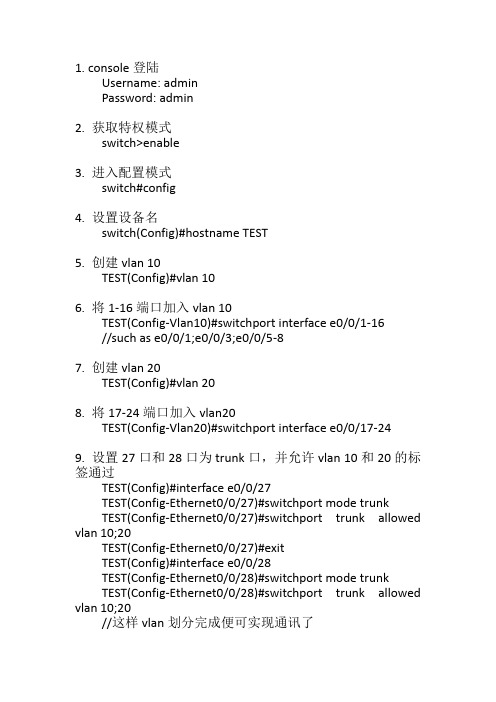
1. console登陆Username: adminPassword: admin2. 获取特权模式switch>enable3. 进入配置模式switch#config4. 设置设备名switch(Config)#hostname TEST5. 创建vlan 10TEST(Config)#vlan 106. 将1-16端口加入vlan 10TEST(Config-Vlan10)#switchport interface e0/0/1-16//such as e0/0/1;e0/0/3;e0/0/5-87. 创建vlan 20TEST(Config)#vlan 208. 将17-24端口加入vlan20TEST(Config-Vlan20)#switchport interface e0/0/17-249. 设置27口和28口为trunk口,并允许vlan 10和20的标签通过TEST(Config)#interface e0/0/27TEST(Config-Ethernet0/0/27)#switchport mode trunkTEST(Config-Ethernet0/0/27)#switchport trunk allowed vlan 10;20TEST(Config-Ethernet0/0/27)#exitTEST(Config)#interface e0/0/28TEST(Config-Ethernet0/0/28)#switchport mode trunkTEST(Config-Ethernet0/0/28)#switchport trunk allowed vlan 10;20//这样vlan划分完成便可实现通讯了10.进入vlan 1配置管理地址TEST(Config)#interface vlan 1TEST(Config-If-Vlan1)#ip address 10.0.0.1 255.255.255.0//这样便可以在与trunk口相直连的路由器端口配置相同网段地址便可通讯11.配置telenet远程管理账户TEST(Config)#telnet-user zooyo password 0 123456//0-7为账户权限等级12.设置接口27和28为上行口,其余口为下行口并进行端口隔离TEST(Config)#isolate-port allowed ethernet 0/0/27;28 13.配置光口复用端口的工作模式TEST(Config)#interface ethernet e0/0/28TEST(Config-Ethernet0/0/28)#combo-forced-mode{sfp-forced|copper-forced}//将28口设置为光口或者为电口14.保存配置TEST#write其他命令:TEST(Config)#no vlan 10 //删除vlan10TEST#show vlan //显示所有vlan信息TEST#show mac-address-table //显示vlan下的MAC地址TEST#set default //恢复出厂后保存配置再重启Are you sure? [Y/N] = yMingZuchenglieguan#writeMingZuchenglieguan#reloadProcess with reboot? [Y/N] yTEST#show switchport interface e0/0/1 //显示端口配置信息TEST#show interface e0/0/1 //显示端口其他信息。
迈普交换机基本配置
1、迈普设备配置基本命令用户名密码为 admin adminSwitch>enableSwith#config?terminalSwith(config)#vlan 70 //新建vlan70Switch(Config-If-Vlan70)#name guanli //将vlan70 命名为guanli Switch(Config-If-Vlan70)#ip address//配置交换机管理地址Switch(Config-If-Vlan70)#no shutdownSwitch(Config-If-Vlan70)#exit//配置交换机路由Swith(config)#vlan 338,440 //新建vlan338,440Switch(Config)# int ethernet 0/0/1 //进入端口Switch(Config-Ethernet1-0/0/1)# no shutdown //打开端口Switch(Config-Ethernet1-0/0/1)# switchport mode access //将端口定义为access口Switch(Config-Ethernet1-0/0/1)# switchport access vlan 338 //将vlan338加入到该端口Switch(Config-Ethernet1-0/0/1)# exitSwitch(Config)# int ethernet 0/0/2-19;ethernet 0/0/20 //进入端口组Switch(Config-Port-Range)#switchport mode access //将端口组定义为access口Switch(Config-Port-Range)#switchport access vlan 440 //将vlan440加入到该端口组Switch(Config-Port-Range)#exitSwitch(Config)#int ethernet 0/0/21 //进入端口Switch(Config-Ethernet1-0/0/21)# switchport mode trunk //将端口定义为trunk口Switch(Config-Ethernet1-0/0/21)#switchport trunk allowed vlan 70;338;440 //该端口允许vlan70,338,440通过Switch(Config-Ethernet1-0/0/21)#exitSwitch(Config)#exitSwitch#write //保存2、迈普设备故障处理基本命令1)查看交换机端口状态2)查看交换机端口描述3)查寻mac地址4)修改交换机配置打开端口 no shutdown 关闭端口 shutdown。
迈普交换机基本配置
1、迈普设备配置基本命令用户名密码为admin adminSwitch>enableSwith#config terminalSwith(config)#vlan 70 //新建vlan70Switch(Config-If-Vlan70)#name guanli //将vlan70 命名为guanli Switch(Config-If-Vlan70)#ip address 172.17.202.21 255.255.255.0//配置交换机管理地址Switch(Config-If-Vlan70)#no shutdownSwitch(Config-If-Vlan70)#exitSwith(config)#ip route-static 0.0.0.0 0.0.0.0 172.17.202.1//配置交换机路由Swith(config)#vlan 338,440 //新建vlan338,440Switch(Config)# int ethernet 0/0/1 //进入端口Switch(Config-Ethernet1-0/0/1)# no shutdown //打开端口Switch(Config-Ethernet1-0/0/1)# switchport mode access //将端口定义为access口Switch(Config-Ethernet1-0/0/1)# switchport access vlan 338 //将vlan338加入到该端口Switch(Config-Ethernet1-0/0/1)# exitSwitch(Config)# int ethernet 0/0/2-19;ethernet 0/0/20 //进入端口组Switch(Config-Port-Range)#switchport mode access //将端口组定义为access口Switch(Config-Port-Range)#switchport access vlan 440 //将vlan440加入到该端口组Switch(Config-Port-Range)#exitSwitch(Config)#int ethernet 0/0/21 //进入端口Switch(Config-Ethernet1-0/0/21)# switchport mode trunk //将端口定义为trunk口Switch(Config-Ethernet1-0/0/21)#switchport trunk allowed vlan 70;338;440 //该端口允许vlan70,338,440通过Switch(Config-Ethernet1-0/0/21)#exitSwitch(Config)#exitSwitch#write //保存2、迈普设备故障处理基本命令1)查看交换机端口状态2)查看交换机端口描述3)查寻mac地址4)修改交换机配置打开端口no shutdown 关闭端口shutdown。
迈普交换机配置
迈普交换机配置完整配置模板:Switch#conf t% Enter configuration commands, one per line. End with CNTL+Z.Switch(config)#vlan 2300 //定义配置的vlan号也就是业务vlan号Switch(config-vlan2300)#port 0/0 tagged //配置级联口也就是trunk口,迈普设备定义为tag口Switch(config-vlan2300)#port 0/5-0/7 untagged //配置业务端口,迈普设备定义为untag 口Switch(config-vlan2300)#exit //退出vlan配置模式Switch(config)#port 0/5-0/7 //进入untag端口下Switch(config-port-range)#pvid 2300 //绑定对应的pvid号也就是vlan号Switch(config-port-range)#exit //退出端口配置模式Switch(config)#igmpsnoop enable //全局开启igmp协议,此配置是针对组播业务开启的Switch(config)#no spanning-tree //全局关闭生成树协议,此配置针对dhcp获得地址慢配置Switch(config)#port 0/0-0/15Switch(config-port-range)#storm-control disable //端口下关闭广播风暴抑制功能,由于默认下端口下只能接收5%的广播包,而组播也是一种广播,如果不关闭此功能的话,组播就会受到限制,导致视频无法接收或视频图像很卡Switch(config-port-range)#exitSwitch(config)#port 0/1-0/15Switch(config-port-range)#keSwitch(config-port-range)#keepalive 100 //此配置为防止单个端口的环路影响到整个交换机的使用Switch(config-port-range)#exitSwitch(config)#logging trap 5 //此配置为开启日志功能,便于后期问题的跟踪Switch(config)#service timestamps log //此配置为给日志打上时间戳Switch(config)#service timestamps debug //此配置为给debug信息打上时间戳Switch(config)#exit //退出配置模式Switch#clock 2010 5 12 14 13 34 //配置交换机的时间,默认时间是1970年Switch#sho clock14:13:38 05/12/2010Switch(config)#interface sw0 //进入sw0端口进行远程管理地址的配置Switch(config)#ip address 1.1.1.1 255.255.255.0 //配置远程管理地址Switch(config)# snmp-server start //启用snmp网管协议Switch(config)# snmp-server community public view default ro //配置团体名为public,默认权限为只读ro,如果使用可读写权限的话,配置是使用rwSwitch#wr //保存配置Are you sure to override /rfa1/startup (Yes|No)?y烽火交换机网管配置SNMP网管配置一、snmp community NAME (ro|rw)配置snmp共同体。
迈普交换机基本配置
迈普交换机配置1、迈普设备配置基本命令用户名密码为:admin admin Switch>enable // 进入普通用户模式 -只能看看Switch#config terminal // 进入全局配置模式 Switch(config)#vlan 70 // 新建 vlan 70 Switch(config-If-Vlan70)#name guanli // 将 vlan70 命名为 guanli Switch(config-If-Vlan70)#ip address172.17.202.21255.255.255.0 // 配置交换机管理地址Switch(config-If-Vlan70)#no shutdown Switch(config-If-Vlan70)#exit Switch(config)#ip route-static 0.0.0.0 0.0.0.0 172.17.202.1// 配置交换机路由Switch(Config)#vlan 338 , 440 // 新建 vlan338 , 440Switch(config)#int ethernet 0/0/1 // 进入端口Switch(Config- Ethernet- 0/0/1)#no shutdown // 打开端口Switch(Config- Ethernet- 0/0/1)#switchport mode access // 将端口定义为 access 口Switch(Config- Ethernet- 0/0/1)#switchport access vlan 388// 将 vlan338 加入该端口Switch(Config- Ethernet- 0/0/1)#exit // 退出Switch(Config)# int ethernet 0/0/12-19;int ethernet 0/0/20 // 进入端口组Switch(Config-Port-Range)#switchport mode access // 将端口组定义为access 口Switch(Config-Port-Range)#switchport access vlan 440 // 将 vlan440 加入该端口组Switch(Config-Port-Range)#exit // 退出Switch(Config)# int ethernet 0/0/21 // 进入端口Switch(Config- Ethernet-0/0/21)# switchport mode trunk// 将端口定义为 trunk 口Switch(Config- Ethernet-0/0/21)#switchport trunk aaowedvlan70;338;440 // 该端口允许 Vlan70,338,440 通过Switch(Config- Ethernet-0/0/21)exit // 退出 0/0/21 端口Switch(Config)# exit // 退出 .Switch#write // 保存 2、迈普设备故障处理基本命令1) 查看交换机端口状态2) 查看交换机端口描述3) 查询 mac 地址4) 修改交换机配置打开端口 no shutdown关闭端口 no shutdown迈普路由器配置与维护enable 普通用户模式只能看看特权用户模式:filesystem文件系统模式COnfigure 全局配置模式 ----interface接口配置模式router*** 路由配置模式ipsccess-list访问列表配置模式VOiCe-POrt语音口配置模式 dial-peer拨号端口配置模式系统配置配置任务命÷命令功能运疔摸式典型例子配置名称hosinunιe改变路由器名称配童模式rtju tt*rf e∣m∏g l#hi uUns*n⅛rm∣ter配置日历IlOCk配置系统日历特权用户模式FoUtrι*do<⅛20D6Ul 15925 LU配置系统用户IIser潘加系统用户配复榄式ΓC)U Ith Cl)TI Hg )⅛usιr∣ EeiPLLTIKIiPUI配置enuble泄码tιnahh?配■超级用户口令配負模式rυukri CUIlfIA L nUbIC PJsSw⅛Kipassword系统配。
迈普MyPower S4300千兆汇聚路由交换机配置手册V2.0_命令手册_03_VLAN和MAC地址命令
目录第1章VLAN配置 (1)1.1 VLAN配置命令 (1)1.1.1 debug gvrp (1)1.1.2 dot1q-tunnel enable (1)1.1.3 dot1q-tunnel tpid (2)1.1.4 gvrp (2)1.1.5 garp timer hold (2)1.1.6 garp timer join (3)1.1.7 garp timer leave (3)1.1.8 garp timer leaveall (3)1.1.9 name (4)1.1.10 private-vlan (4)1.1.11 private-vlan association (5)1.1.12 show dot1q-tunnel (5)1.1.13 show garp (6)1.1.14 show gvrp (6)1.1.15 show vlan (6)1.1.16 show vlan-translation (8)1.1.17 switchport access vlan (8)1.1.18 switchport interface (8)1.1.19 switchport mode (9)1.1.20 switchport trunk allowed vlan (9)1.1.21 switchport trunk native vlan (10)1.1.22 vlan (10)1.1.23 vlan-translation (11)1.1.24 vlan-translation enable (11)1.1.25 vlan-translation miss drop (12)1.1.26 vlan ingress enable (12)1.2 动态vlan配置命令 (12)1.2.1 dynamic-vlan mac-vlan prefer (12)1.2.2 dynamic-vlan subnet-vlan prefer (13)1.2.3 mac-vlan (13)1.2.4 mac-vlan vlan (13)1.2.5 protocol-vlan (14)1.2.6 show dynamic-vlan prefer (14)1.2.7 show mac-vlan (15)1.2.8 show mac-vlan interface (15)1.2.9 show protocol-vlan (15)1.2.10 show subnet-vlan (16)1.2.11 show subnet-vlan interface (16)1.2.12 subnet-vlan (16)1.2.13 switchport mac-vlan enable (17)1.2.14 switchport subnet-vlan enable (17)1.3 Voice VLAN配置命令 (18)1.3.1 show voice-vlan (18)1.3.2 switchport voice-vlan enable (18)1.3.3 voice-vlan (19)1.3.4 voice-vlan vlan (19)第2章MAC地址表配置命令 (20)2.1 MAC地址表配置命令 (20)2.1.1 mac-address-table aging-time (20)2.1.2 mac-address-table static|blackhole (20)2.1.3 show mac-address-table (21)2.2 MAC地址绑定配置命令 (21)2.2.1 clear port-security dynamic (21)2.2.2 show port-security (22)2.2.3 show port-security address (22)2.2.4 show port-security interface (23)2.2.5 switchport port-security (24)2.2.6 switchport port-security convert (24)2.2.7 switchport port-security lock (24)2.2.8 switchport port-security mac-address (25)2.2.9 switchport port-security maximum (25)2.2.10 switchport port-security timeout (25)2.2.11 switchport port-security violation (26)第1章VLAN配置1.1 VLAN配置命令1.1.1 debug gvrp命令:debug gvrpno debug gvrp功能:打开交换机的gvrp的调试开关;本命令的no操作为关闭该调试开关。
迈普交换机VLAN配置
VLAN7.1 VLAN7.1.1 VLANVLAN Virtual Local Area NetworkVLAN VLAN IEEE 802.1Q VLAN VLAN IEEE802.1QVLAN VLAN 802.1Q VLAN MAC VLAN IP VLAN IP VLAN VLAN VLANMy Power S41xx 802.1Q VLANVLANu VLANuu7.1.2 VLANVLANu VLANu VLANu VLANvlan vlan_idvlan vlan_id VLAN VLAN 1 4094 VLANVLAN7.1.2.2 VLANdescription stringString VLAN 32VLANVLAN vid7.1.2.3 VLANport port-list{forbidden|tagged|untagged}no port port-listport-list VLANforbidden|tagged|untagged VLANVLAN7.1.3 VLANshow vlan [vlan_id]vlan_id VLAN<CR> VLANEnable VLANSwitch# show vlan---- ---- -------------------------------- --------------------------------NO.VID VLAN-Name P ort N umber---- ---- -------------------------------- --------------------------------11default[U]0/00/10/20/30/40/50/60/70/80/90/10 0/11 0/12 0/13 0/140/15 1/0 1/1 2/02 5 VLAN0005 [M]2/17.2 VLANMyPowe S41xx 96 VLANu IPu VLAN-IDu VLANu7.2.1 IPIP IPip address ipaddress ipmaskipaddress IPipmask IP7.2.2 VLAN-IDVLAN VLAN VLAN VLAN VLANvlan-id vlan-novlan-no VLAN VLAN 1 4094VLAN-ID 07.2.3 VLANVLANdescription interface-nameinterface-name VLANSW3 VLAN-ID 3 IP 128.255.9.61 255.255.252.0vlan3port0/1-0/3untaggedexitVLAN 3port 0/1-0/3pvid 3exitinterface sw3ip address128.255.9.61 255.255.252.0 vlan-id3exit IP VLAN-ID7.2.4interface-number Enablesw50Switch#show interface sw50sw (unit number 50,vlan 111, enabled, link up)Flags: (0x8863) UP BROADCAST MUL TICAST ARP RUNNINGType: ETHERNET_CSMACDInternet address: 111.0.0.1Netmask 0xff000000 Subnetmask 0xffffff00Broadcast address: 111.0.0.255Ethernet address is 00:01:7a:4c:58:53Metric is 0Maximum Transfer Unit size is 15001801003390 octets received3877382 octets sent17397089 packets received48199 packets sent646 broadcast packets received405 broadcast packets sent5 multicast packets received29813 multicast packets sent0 input discards0 output discards0 input unknown protocols2364040 input errors0 output errors7.2.510.0.0.3/167-17-1 Switch1 vlan 0/0 vlan2 untag 0/7 vlan2 vlan3 vlan tagSwitch1Switch#show running-configvlan 1description defaultport 0/0-2/0 untaggedvlan 2 // vlan2port 0/7 tagged // 0/7 vlan2 , 0/7 taggedport 0/0 untagged // 0/0 vlan2 , 0/0 untaggedvlan 3 // vlan3description VLAN0003port 0/7 tagged // 0/7 vlan3 , 0/7 taggedexitport0/0 // 0/0 vlan 2pvid 2exitport 0/7 // 0/7 vlan 3pvid 3exitSwitch#show vlan----- -------- ------------------- ------------------------------------------------------NO.VID VLAN-Name Port N umber----- -------- ------------------ ------------------------------------------------------11default[U]0/00/10/20/30/40/5 0/6 0/7 0/8 0/90/10 0/11 0/12 0/13 0/140/15 0/16 1/0 2/022VLAN0002[U]0/0[M]0/733VLAN0003[M]0/7Switch2 vlan 0/0 0/1 vlan2 untag 0/7 vlan2 vlan3 vlan tagSwitch2Switch#show running-configvlan 1description defaultport 0/0-2/0 untaggedvlan 2description VLAN0002port 0/7 taggedport 0/0-0/1 untaggedvlan 3port 0/7 taggedexitport 0/0pvid 2exitport 0/1pvid 2exitport 0/7pvid 3exitSwitch#show vlan---- ---- ----------------------- ------------------------------------------------------------NO.V ID VLAN-Name Port N umber---- ---- ---------------------- -------------------------------------------------------------11default[U]0/00/10/20/30/40/5 0/6 0/7 0/8 0/90/10 0/11 0/12 0/13 0/140/15 0/16 1/0 2/0 22VLAN0002[U]0/00/1[M]0/733VLAN0003[M]0/7Switch3 0/0 0/1 vlan2 untagSwitch3Switch#show running-configvlan 1description defaultport 0/0-2/0 untaggedvlan 2description VLAN0002port 0/0-0/1 untaggedexitport 0/0pvid 2exitpvid 2exitSwitch#show vlan---- ---- --------------------- ----------------------------------------------------NO.V ID VLAN-Name Port N umber---- ---- ------------------------------- ----------------------------------------------------11default[U]0/00/10/20/30/40/5 0/6 0/7 0/8 0/90/10 0/11 0/12 0/13 0/140/15 0/16 1/0 2/022VLAN0002[U]0/00/1PC2 PC1 PC2 Switch2 0/0 vlan2 vid Switch2 0/7 vlan2 tag Switch1 0/7 0/7 tag vid 2 Switch1 0/0 vlan2 0/0 pvid 2 0/0 0/0 untag PC1PC3 PC2 PC3 Switch3 0/1 vlan2 vid Switch3 0/0 vlan2 untag Switch2 0/1 untag vlan2 Switch2 0/1 vid 2 vlan Switch2 0/0 0/1 vlan2 PC2 PC3。
迈普交换机配置
迈普交换机配置1、配置举例2、配置交换机名称为“Switch_1”。
语法描述Switch>enable 进入到Enable模式Switch#configure terminal 进入到全局配置模式Switch(config)#hostname Switch_1 配置交换机名称3、设置enable密码(config t 模式下):enable password [0 | 7 ] string 设置enable密码,string为所要配置的密码4、创建VLAN:vlan [vlan-num]语法描述vlan-num 打开VLAN命令,并进入到VLAN配置模式,值的范围为1~40945、添加VLAN描述:description string string为所增加描述的内容6、在VLAN下添加端口:port port-list untag| tag 配置端口为打标模式或不打标模式7、在端口下绑定PVID号(也就是端口的默认VLAN号):pvid pvid-num 在端口配置模式下配置(port下)8、启用全局的igmpsnoop:igmpsnoop enable9、在端口下禁用广播风暴抑制功能:storm-control disable10、交换机三网合一配置Switch#show run //查看配置vlan 1 //删除vlan 1中的端口description defaultport 0/0-0/7untaggedvlan 20description VLAN 20 /创建上网VLAN 20port 0/0 tagged /tagged为打标也就是trunkport 0/1 untagged /untagged为非打标也就是accessport 0/1 pvid 20 /设置端口1的PVID为20vlan 2103description VLAN2103 /创建电话VLAN 2103port 0/0 tagged /tagged为打标也就是trunkport 0/2 untagged /untagged为非打标也就是accessport 0/2 pvid 2103 /设置端口2的PVID为2103vlan 2104description VLAN2104 /创建IPTV VLAN 2104port 0/0 tagged /tagged为打标也就是trunkport 0/3-0/6 untagged /untagged为非打标也就是accessport 0/3-0/6 pvid 2104 /设置端口3-6的PVID为2104exit /退出igmpsnoop enable /开启IGMP组播功能Spanning-tree disable /关闭生成树协议port 0/0storm-control disable /广播风暴控制抑制功能关闭exit /退出wr /保存11、端口环路配置迈普交换机环路检测功能需要在端口下配置:keepalive ,举例说明比如您要在0/1端口下开启端口环路检测功能的话port0/1keepalive 100 //其中100为时间,单位是秒,此命令的意思是每100秒检测一次端口环路12、清空配置迈普交换机清空配置的命令为:在特权模式下也就是#后输入filesystem 回车,然后 dir 可以看到显示出来的文件有个叫startup的,这个文件就是存储配置的文件,把这个文件删除就可以清空配置,使用命令delete startup 将startup文件删除,然后再关电重新启动交换机即可。
迈普交换机配置指导书
迈普交换机配置指导书1.通过Console口配置交换机(同HW2016一样)通过配置线将终端的RS-232串口与交换机的Console口相连。
配置用PCPC机串口MyPower S3000B 配置口2.迈普交换机基本配置enacon t 进入配置模式vlan 2 创建vlan 2port 0/0 tagexlayer2-mode disable 关闭2层模式interface sw0 进入SW0接口ip address 192.168.x.x 255.255.255.0 配置管理地址x范围(2-254) vlan-id 2 管理vlanexitip route 0.0.0.0 0.0.0.0 192.168.x.1 静态路由,指向管理地址x网关enable password level 15 admin 为交换机密码igmpsnoop en 打开组播exitwr3.中兴交换机配置实例Switch# show runBuild configration... doneCurrent configration: 1701 bytesuser admin password 7 OWRW[WWW\W user admin privilege 15enable password OWRW[WWW\W encryptservice password-encryptservice login-securelayer2-mode disablevlan 1description defaultport 0/0-0/15 untaggedvlan 2description VLAN0002port 0/0 taggedvlan 1065description VLAN1065port 0/0-0/15 untaggedvlan 2103description VLAN2103port 0/0-0/15 taggedvlan 2104description VLAN2104port 0/0-0/15 taggedexitigmpsnoop enable!slot 0port 0/1pvid 1065storm-control disableexitport 0/2pvid 1065exitport 0/3pvid 1065storm-control disable exitport 0/4pvid 1065storm-control disable exitport 0/5pvid 1065storm-control disable exitport 0/6pvid 1065storm-control disable exitport 0/7pvid 1065storm-control disable exitport 0/8pvid 1065storm-control disable exitport 0/9pvid 1065storm-control disable exitport 0/10pvid 1065storm-control disable exitport 0/11pvid 1065storm-control disable exitport 0/12pvid 1065storm-control disable exitport 0/13pvid 1065exitport 0/14pvid 1065storm-control disableexitport 0/15pvid 1065storm-control disableexitinterface loopback0ip address 127.0.0.1 255.0.0.0exitinterface sw0ip address 192.168.14.2 255.255.255.0vlan-id 2exitip route 0.0.0.0 0.0.0.0 192.168.14.1Switch#3.1 举例说明例:1端口为主端口,2,3端口为下挂交换机端口,4,5端口为普通农带,6-10端口为家庭网关数据,11-12为单个可视电话用户,13端口为网络IP电话用,14端口为带网络IP电话的家庭网关网户,15端口为IP电话用户。
迈普交换机VLAN配置
VLAN7.1 VLAN7.1.1 VLANVLAN Virtual Local Area NetworkVLAN VLAN IEEE 802.1Q VLAN VLAN IEEE802.1QVLAN VLAN 802.1Q VLAN MAC VLAN IP VLAN IP VLAN VLAN VLANMy Power S41xx 802.1Q VLANVLANu VLANuu7.1.2 VLANVLANu VLANu VLANu VLANvlan vlan_idvlan vlan_id VLAN VLAN 1 4094 VLANVLAN7.1.2.2 VLANdescription stringString VLAN 32VLANVLAN vid7.1.2.3 VLANport port-list{forbidden|tagged|untagged}no port port-listport-list VLANforbidden|tagged|untagged VLANVLAN7.1.3 VLANshow vlan [vlan_id]vlan_id VLAN<CR> VLANEnable VLANSwitch# show vlan---- ---- -------------------------------- --------------------------------NO.VID VLAN-Name P ort N umber---- ---- -------------------------------- --------------------------------11default[U]0/00/10/20/30/40/50/60/70/80/90/10 0/11 0/12 0/13 0/140/15 1/0 1/1 2/02 5 VLAN0005 [M]2/17.2 VLANMyPowe S41xx 96 VLANu IPu VLAN-IDu VLANu7.2.1 IPIP IPip address ipaddress ipmaskipaddress IPipmask IP7.2.2 VLAN-IDVLAN VLAN VLAN VLAN VLANvlan-id vlan-novlan-no VLAN VLAN 1 4094VLAN-ID 07.2.3 VLANVLANdescription interface-nameinterface-name VLANSW3 VLAN-ID 3 IP 128.255.9.61 255.255.252.0vlan3port0/1-0/3untaggedexitVLAN 3port 0/1-0/3pvid 3exitinterface sw3ip address128.255.9.61 255.255.252.0 vlan-id3exit IP VLAN-ID7.2.4interface-number Enablesw50Switch#show interface sw50sw (unit number 50,vlan 111, enabled, link up)Flags: (0x8863) UP BROADCAST MUL TICAST ARP RUNNINGType: ETHERNET_CSMACDInternet address: 111.0.0.1Netmask 0xff000000 Subnetmask 0xffffff00Broadcast address: 111.0.0.255Ethernet address is 00:01:7a:4c:58:53Metric is 0Maximum Transfer Unit size is 15001801003390 octets received3877382 octets sent17397089 packets received48199 packets sent646 broadcast packets received405 broadcast packets sent5 multicast packets received29813 multicast packets sent0 input discards0 output discards0 input unknown protocols2364040 input errors0 output errors7.2.510.0.0.3/167-17-1 Switch1 vlan 0/0 vlan2 untag 0/7 vlan2 vlan3 vlan tagSwitch1Switch#show running-configvlan 1description defaultport 0/0-2/0 untaggedvlan 2 // vlan2port 0/7 tagged // 0/7 vlan2 , 0/7 taggedport 0/0 untagged // 0/0 vlan2 , 0/0 untaggedvlan 3 // vlan3description VLAN0003port 0/7 tagged // 0/7 vlan3 , 0/7 taggedexitport0/0 // 0/0 vlan 2pvid 2exitport 0/7 // 0/7 vlan 3pvid 3exitSwitch#show vlan----- -------- ------------------- ------------------------------------------------------NO.VID VLAN-Name Port N umber----- -------- ------------------ ------------------------------------------------------11default[U]0/00/10/20/30/40/5 0/6 0/7 0/8 0/90/10 0/11 0/12 0/13 0/140/15 0/16 1/0 2/022VLAN0002[U]0/0[M]0/733VLAN0003[M]0/7Switch2 vlan 0/0 0/1 vlan2 untag 0/7 vlan2 vlan3 vlan tagSwitch2Switch#show running-configvlan 1description defaultport 0/0-2/0 untaggedvlan 2description VLAN0002port 0/7 taggedport 0/0-0/1 untaggedvlan 3port 0/7 taggedexitport 0/0pvid 2exitport 0/1pvid 2exitport 0/7pvid 3exitSwitch#show vlan---- ---- ----------------------- ------------------------------------------------------------NO.V ID VLAN-Name Port N umber---- ---- ---------------------- -------------------------------------------------------------11default[U]0/00/10/20/30/40/5 0/6 0/7 0/8 0/90/10 0/11 0/12 0/13 0/140/15 0/16 1/0 2/0 22VLAN0002[U]0/00/1[M]0/733VLAN0003[M]0/7Switch3 0/0 0/1 vlan2 untagSwitch3Switch#show running-configvlan 1description defaultport 0/0-2/0 untaggedvlan 2description VLAN0002port 0/0-0/1 untaggedexitport 0/0pvid 2exitpvid 2exitSwitch#show vlan---- ---- --------------------- ----------------------------------------------------NO.V ID VLAN-Name Port N umber---- ---- ------------------------------- ----------------------------------------------------11default[U]0/00/10/20/30/40/5 0/6 0/7 0/8 0/90/10 0/11 0/12 0/13 0/140/15 0/16 1/0 2/022VLAN0002[U]0/00/1PC2 PC1 PC2 Switch2 0/0 vlan2 vid Switch2 0/7 vlan2 tag Switch1 0/7 0/7 tag vid 2 Switch1 0/0 vlan2 0/0 pvid 2 0/0 0/0 untag PC1PC3 PC2 PC3 Switch3 0/1 vlan2 vid Switch3 0/0 vlan2 untag Switch2 0/1 untag vlan2 Switch2 0/1 vid 2 vlan Switch2 0/0 0/1 vlan2 PC2 PC3。
迈普交换机配置文件
Adminadmin一:24口POE交换机conf t \\进入配置模式hostname LS \\设备名vlan 919,929 \\设备上需要通过的VLANinterface ethernet 1/1-22 \\进入1口至22口switchport mode access \\商品配置成ACCESS模式switchport access vlan 919 \\AP管理VLANexitinterface ethernet 1/23-26 \\进入23至26口switchport mode trunk \\端口配置成TRUN口(用于互联或者上联)switchport trunk allowed vlan all \\允许所有VLAN通过exitinterface vlan 929 \\交换机管理VLANip add 172.16.172.25 255.255.255.0 \\交换机的管理地址exitno int vlan 1ip default-gateway 172.16.172.1 \\交换机网关power inline enable \\开启POE供电exitwr \\保存配置查勘MAC地址show mac-address-table二:8口POE交换机enaconf t \\进入配置模式hostname LS \\设备名vlan 919,929 \\设备上需要通过的VLANinterface ethernet 1/1-7 \\进入1口至7口switchport mode access \\端口配置成ACCESS模式switchport access vlan 919 \\AP管理VLANexitinterface ethernet 1/8-9 \\进入8至9口switchport mode trunk \\端口配置成TRUN口(用于互联或者上联)switchport trunk allowed vlan all \\允许所有VLAN通过exitinterface vlan 929 \\交换机管理VLANip add 172.16.172.25 255.255.255.0 \\交换机的管理地址exitno int vlan 1ip default-gateway 172.16.172.1 \\交换机网关power inline enable \\开启POE供电exitwr \\保存配置在#模式下面,可以用用PING 命令来ping 网关地址看看是否连通。
迈普交换机基本配置
迈普交换机配置1、迈普设备配置基本命令用户名密码为:admin adminSwitch>enable //进入普通用户模式-只能看看Switch#config terminal //进入全局配置模式Switch(config)#vlan 70 //新建vlan 70Switch(config-If-Vlan70)#name guanli //将vlan70命名为guanli Switch(config-If-Vlan70)#ip address 172.17.202.21255.255.255.0//配置交换机管理地址Switch(config-If-Vlan70)#no shutdownSwitch(config-If-Vlan70)#exitSwitch(config)#ip route-static 0.0.0.0 0.0.0.0 172.17.202.1//配置交换机路由Switch(Config)#vlan 338,440 //新建vlan338,440Switch(config)#int ethernet 0/0/1 //进入端口Switch(Config- Ethernet- 0/0/1)#no shutdown //打开端口Switch(Config- Ethernet- 0/0/1)#switchport mode access//将端口定义为access口Switch(Config- Ethernet- 0/0/1)#switchport access vlan 388//将vlan338加入该端口Switch(Config- Ethernet- 0/0/1)#exit //退出Switch(Config)# int ethernet 0/0/12-19;int ethernet 0/0/20 //进入端口组Switch(Config-Port-Range)#switchport mode access //将端口组定义为access口Switch(Config-Port-Range)#switchport access vlan 440//将vlan440加入该端口组Switch(Config-Port-Range)#exit //退出Switch(Config)# int ethernet 0/0/21 //进入端口Switch(Config- Ethernet-0/0/21)# switchport mode trunk//将端口定义为trunk口Switch(Config- Ethernet-0/0/21)#switchport trunk aaowed vlan70;338;440 //该端口允许Vlan70,338,440通过Switch(Config- Ethernet-0/0/21)exit //退出0/0/21 端口Switch(Config)# exit //退出.Switch#write //保存2、迈普设备故障处理基本命令1)查看交换机端口状态2)查看交换机端口描述3)查询mac地址4)修改交换机配置打开端口no shutdown关闭端口no shutdown迈普路由器配置与维护enable 普通用户模式只能看看特权用户模式:filesystem 文件系统模式configure 全局配置模式---- interface 接口配置模式router*** 路由配置模式ipsccess-list 访问列表配置模式voice-port 语音口配置模式dial-peer 拨号端口配置模式系统配置精选文档。
- 1、下载文档前请自行甄别文档内容的完整性,平台不提供额外的编辑、内容补充、找答案等附加服务。
- 2、"仅部分预览"的文档,不可在线预览部分如存在完整性等问题,可反馈申请退款(可完整预览的文档不适用该条件!)。
- 3、如文档侵犯您的权益,请联系客服反馈,我们会尽快为您处理(人工客服工作时间:9:00-18:30)。
VLAN7.1 VLAN7.1.1 VLANVLAN Virtual Local Area NetworkVLAN VLAN IEEE 802.1Q VLAN VLAN IEEE802.1QVLAN VLAN 802.1Q VLAN MAC VLAN IP VLAN IP VLAN VLAN VLANMy Power S41xx 802.1Q VLANVLANu VLANuu7.1.2 VLANVLANu VLANu VLANu VLANvlan vlan_idvlan vlan_id VLAN VLAN 1 4094 VLANVLAN7.1.2.2 VLANdescription stringString VLAN 32VLANVLAN vid7.1.2.3 VLANport port-list{forbidden|tagged|untagged}no port port-listport-list VLANforbidden|tagged|untagged VLANVLAN7.1.3 VLANshow vlan [vlan_id]vlan_id VLAN<CR> VLANEnable VLANSwitch# show vlan---- ---- -------------------------------- --------------------------------NO.VID VLAN-Name P ort N umber---- ---- -------------------------------- --------------------------------11default[U]0/00/10/20/30/40/50/60/70/80/90/10 0/11 0/12 0/13 0/140/15 1/0 1/1 2/02 5 VLAN0005 [M]2/17.2 VLANMyPowe S41xx 96 VLANu IPu VLAN-IDu VLANu7.2.1 IPIP IPip address ipaddress ipmaskipaddress IPipmask IP7.2.2 VLAN-IDVLAN VLAN VLAN VLAN VLANvlan-id vlan-novlan-no VLAN VLAN 1 4094VLAN-ID 07.2.3 VLANVLANdescription interface-nameinterface-name VLANSW3 VLAN-ID 3 IP 128.255.9.61 255.255.252.0vlan3port0/1-0/3untaggedexitVLAN 3port 0/1-0/3pvid 3exitinterface sw3ip address128.255.9.61 255.255.252.0 vlan-id3exit IP VLAN-ID7.2.4interface-number Enablesw50Switch#show interface sw50sw (unit number 50,vlan 111, enabled, link up)Flags: (0x8863) UP BROADCAST MUL TICAST ARP RUNNINGType: ETHERNET_CSMACDInternet address: 111.0.0.1Netmask 0xff000000 Subnetmask 0xffffff00Broadcast address: 111.0.0.255Ethernet address is 00:01:7a:4c:58:53Metric is 0Maximum Transfer Unit size is 15001801003390 octets received3877382 octets sent17397089 packets received48199 packets sent646 broadcast packets received405 broadcast packets sent5 multicast packets received29813 multicast packets sent0 input discards0 output discards0 input unknown protocols2364040 input errors0 output errors7.2.510.0.0.3/167-17-1 Switch1 vlan 0/0 vlan2 untag 0/7 vlan2 vlan3 vlan tagSwitch1Switch#show running-configvlan 1description defaultport 0/0-2/0 untaggedvlan 2 // vlan2port 0/7 tagged // 0/7 vlan2 , 0/7 taggedport 0/0 untagged // 0/0 vlan2 , 0/0 untaggedvlan 3 // vlan3description VLAN0003port 0/7 tagged // 0/7 vlan3 , 0/7 taggedexitport0/0 // 0/0 vlan 2pvid 2exitport 0/7 // 0/7 vlan 3pvid 3exitSwitch#show vlan----- -------- ------------------- ------------------------------------------------------NO.VID VLAN-Name Port N umber----- -------- ------------------ ------------------------------------------------------11default[U]0/00/10/20/30/40/5 0/6 0/7 0/8 0/90/10 0/11 0/12 0/13 0/140/15 0/16 1/0 2/022VLAN0002[U]0/0[M]0/733VLAN0003[M]0/7Switch2 vlan 0/0 0/1 vlan2 untag 0/7 vlan2 vlan3 vlan tagSwitch2Switch#show running-configvlan 1description defaultport 0/0-2/0 untaggedvlan 2description VLAN0002port 0/7 taggedport 0/0-0/1 untaggedvlan 3port 0/7 taggedexitport 0/0pvid 2exitport 0/1pvid 2exitport 0/7pvid 3exitSwitch#show vlan---- ---- ----------------------- ------------------------------------------------------------NO.V ID VLAN-Name Port N umber---- ---- ---------------------- -------------------------------------------------------------11default[U]0/00/10/20/30/40/5 0/6 0/7 0/8 0/90/10 0/11 0/12 0/13 0/140/15 0/16 1/0 2/0 22VLAN0002[U]0/00/1[M]0/733VLAN0003[M]0/7Switch3 0/0 0/1 vlan2 untagSwitch3Switch#show running-configvlan 1description defaultport 0/0-2/0 untaggedvlan 2description VLAN0002port 0/0-0/1 untaggedexitport 0/0pvid 2exitpvid 2exitSwitch#show vlan---- ---- --------------------- ----------------------------------------------------NO.V ID VLAN-Name Port N umber---- ---- ------------------------------- ----------------------------------------------------11default[U]0/00/10/20/30/40/5 0/6 0/7 0/8 0/90/10 0/11 0/12 0/13 0/140/15 0/16 1/0 2/022VLAN0002[U]0/00/1PC2 PC1 PC2 Switch2 0/0 vlan2 vid Switch2 0/7 vlan2 tag Switch1 0/7 0/7 tag vid 2 Switch1 0/0 vlan2 0/0 pvid 2 0/0 0/0 untag PC1PC3 PC2 PC3 Switch3 0/1 vlan2 vid Switch3 0/0 vlan2 untag Switch2 0/1 untag vlan2 Switch2 0/1 vid 2 vlan Switch2 0/0 0/1 vlan2 PC2 PC3。