DT测温仪说明书
红外测温仪技术说明
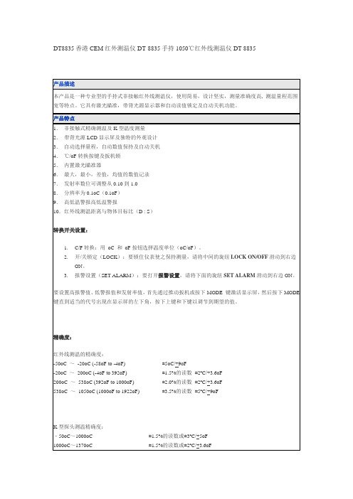
红外线测温的精确度:
-50oC~-20oC (-58oF to -4oF)
±5oC/+9oF
-20oC~200oC (-4oF to 392oF)
±1.5%的读数±2ºC/+3.6oF
200oC~538oC (392oF to 1000oF)
±2.0%的读数±2ºC/+3.6oF
538oC~1050oC (1000oF to 1922oF)
3.自动选择量程,自动数值保持及自动关机
4.℃/oF转换按键及扳机锁
5.内置激光瞄准器
6.最大,最小,差值,均值的数值记录
7.发射率数位可调整从0.10到1.0
8.分辨率为0.1oC(0.1oF)
9.高低温警报高低温警报
10.红外线测温距离与物体目标比(D : S)
转换开关设置:
1.C/F转换:用oC和oF按钮选择温度单位(oC/oF)。
DT8835香港CEM红外测温仪DT-8835手持1050℃红外线测温仪DT 8835
产品描述
本产品是一种专业型的手持式非接触红外线测温仪,使用简易,设计坚实,测量准确度高,测温量程范围宽等特点。它具有激光瞄准,带背光源显示器和自动读值锁定及自动关机功能。
产品特点
1.非接触式精确测温及K型温度测量
2.带背光源LCD显示屏及独特的外观设计
2.开/关锁定(LOCK):要锁住仪表使之保持测量,请将中间的旋纽LOCK ON/OFF滑动到右边ON。
3.报警设置(SET ALARM):要打开报警设置,请将下面的旋纽SET ALARM滑动到右边ON。
要设置高报警值、低警报值和发射率值,首先通过推动扳机或按下MODE键激活显示屏,然后按下MODE键直到适当的代号出现在显示屏的左下角,按下上键和下键以调节到期望的值。
斯坦达DT-2说明书

斯坦达DT-2说明书
1、斯坦达DT-2温控器是电子计量产品,其使用寿命为五年,每年需进行周期检验。
2、本斯坦达DT-2温控器只能按照本公司规定的目的和方法使用。
未经授权的修改和使用非本公司所出售或推荐的零配件都有可能导致本系统出现故障,甚至损坏。
3、使用前请您详细阅读该说明书。
设计部门的工作人员请重点参阅性能指标、外形尺寸、机械安装及电气连接;安装人员请重点参阅外形尺寸、机械安装、电气连接及异常现象处理;使用人员请重点参阅基本操作及异常现象处理。
4、每台斯坦达DT-2温控器在使用前应进行功能测试,以保证使用的可靠性及测量、控制的精度。
5、斯坦达DT-2温控器在运输时应采用原包装,以免造成机械损坏。
6、斯坦达DT-2温控器不使用时,请进行防潮处理。
7、斯坦达DT-2温控器使用时应注意电源等级(无特殊说明时,一般为AC220V)。
8、当您准备使用斯坦达DT-2温控器时,请仔细阅读该说明书的电气连接部分,确认连接无误后再给斯坦达DT-2温控器送电!
9、为保证斯坦达DT-2温控器输入信号质量,斯坦达DT-2温控器正常运行前务必拧紧传感器插头。
10、在干式变压器进行耐压测试前,必须将传感器插头与斯坦达DT-2温控器分离,以避免斯坦达DT-2温控器被损坏。
11、切勿用打火机等明火对传感器探头进行模拟温升试验,否则会损坏Pt100传感器。
12、避免在含有二氧化硫(SO2)或其他腐蚀性气体的环境中使用本斯坦达DT-2温控器,否则会使继电器的触点失效。
便携式红外测温仪DT-8869H 中文说明书
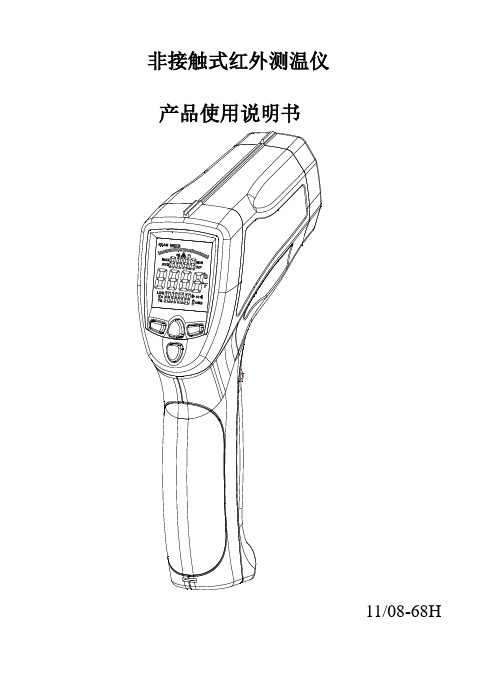
非接触式红外测温仪产品使用说明书11/08-68H目录简介………………………………………………….. 特征…………………………………………………... 用途…………………………………………………. 安全条款……………………………………………… 测量距离与物体目标比………………………………技术指标……………………………………………… 面板描述……………………………………………… 显示屏描述……………………………………………按键描述………………………………………………使用方法……………………………………………... 电池更换……………………………………………... 注意事项……………………………………………… 产品维护………………………………………………简介欢迎选购本公司红外测温仪。
本品是一种专业型的手持式非接触红外线测温仪,有使用简易,设计坚实,测量准确度高,测温量程范围宽等特点。
它具有激光瞄准、带背光灯的LCD、最大值、最小值、差值、平均值、数据保持、高低温报警、发射率可调及自动关机等功能。
该手持式红外测温仪可以用来测量传统的接触式红外测温仪很难测量的物体表面温度。
(如:移动的物体、带电的物体、不易接触的物体等)如使用恰当且注意保养,此仪表可有效使用多年。
特征:●快速测量功能。
●非接触式精确测温●内置双激光瞄准器,可以更加快速准确地瞄准目标●双显示屏的外壳设置●自动记录读数●可调节发射率,0.1~1.0。
●最大/最小/均值/差值温度显示●带背光的液晶显示屏●自动量程选择和分辨率为0.1ºC(0.1ºF)●扳机锁定功能●高低温报警设置●数据储存功能(LOG)●通过USB传输数据到PC用途:●用于食品检测,安检,火检,注塑,喷漆,墨水和柴油机的保养等.安全条款●当激光光束打开时,请小心使用.●请不要将激光光束对着人或动物的眼睛●请不要将激光光束射向物体表面反射到人的眼睛里●请不要将激光光束射到任何易爆气体测量距离与物体目标比:光学测量距离与物体目标比(D:S)=50:1例如:仪表的视场是50:1,即若仪器离被测物体50英尺时,则被测物体的直径不能小于1英寸。
测温仪使用说明书

测温仪使用说明书感谢您选择我们的测温仪。
为了确保您正确、安全地使用本产品,请仔细阅读本使用说明书。
产品概述测温仪是一款非接触式测温设备,适用于人体温度测量。
它采用红外线技术,能够快速、准确地测量体温,广泛应用于医疗、公共场所等领域。
主要特点•非接触式测温,减少交叉感染风险•快速响应,测量时间小于1秒•高精度,温度误差小于±0.5℃•易于操作,一键式开关•数据存储功能,可存储1000次测量数据包装内容•测温仪主机安装与启动1.取出测温仪,确认电池电量充足。
如果电量不足,请先给测温仪充电。
2.将测温仪放置在平稳的台面上,确保红外线传感器正对被测物体。
3.按下开机键,测温仪开始工作。
测量操作1.按下开机键,测温仪开始工作。
2.将测温仪对准被测物体,保持适当距离(建议1-3米)。
3.等待测温仪显示稳定后,读取温度数值。
数据查看与删除1.按下数据键,测温仪进入数据查看模式。
2.上下键切换查看不同测量数据。
3.按下删除键,可删除单个或全部测量数据。
4.使用充电线将测温仪连接至电源。
5.充电过程中,测温仪会显示充电状态。
6.充电完成后,关闭测温仪并拔掉充电线。
注意事项•请避免将测温仪暴露在高温、潮湿环境中。
•请勿用湿手操作测温仪。
•测量过程中,请保持测温仪与被测物体之间距离适当。
•请勿用测温仪测量易燃、易爆物体。
故障处理•如果测温仪无法开机,请检查电池电量是否充足。
•如果测温仪显示异常,请尝试重启设备。
•如果仍无法解决问题,请与生产厂家联系。
保修政策本产品自购买之日起,享受一年内免费保修服务。
保修期内,如产品出现非人为损坏问题,我们将免费提供维修或更换服务。
客服与技术支持如需咨询产品相关信息或技术支持,请拨打以下电话:电话:XXX-XXXX-XXXX邮箱:*************我们将竭诚为您服务。
祝您使用愉快!故障处理(续)•如果测温仪的温度读数不稳定或者有误差,请检查测量环境是否符合要求,如是否有强光或热源的干扰。
DT系列电子体温计 说明书
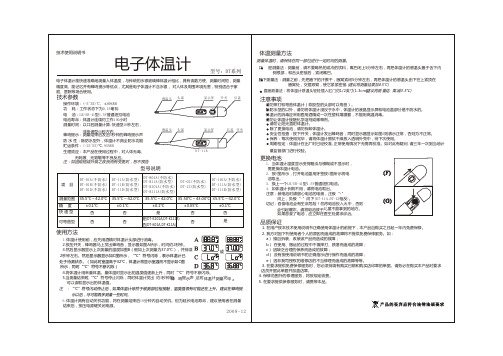
电子体温计 型号:DT系列
电子体温计能快速准确地测量人体温度,与传统的水银玻璃棒体温计相比,具有读数方便、测量时间短,测量
精度高、能记忆并有蜂鸣提示等优点,尤其是电子体温计不含水银, 对人体及周围环境无害,特别适合于家
庭、医院等场合使用。
技术参数
感温头 头部
显示屏 开关 后盖
操作环境:(-5~35)℃, ≤80%RH 功 耗:工作状态下为0.15毫瓦 电 池:LR/SR-41型1.5V普通纽扣电池 电池寿命:体温计连续约工作100小时
注意事项
请勿摔打和弯曲体温计(软胶型的头部可以弯曲)。 除防水型的以外,请勿将体温计浸没于水中,体温计的液晶显示屏和电池盖部分是不防水的。 体温计的消毒应采用医用酒精或一次性塑料薄膜套,不能用高温消毒。 请勿让体温计接触化学溶剂或稀释剂。
请勿让阳光直射体温计。 除了更换电池,请勿拆卸体温计。 安全性检查:按下开关,体温计发出蜂鸣音,同时显示器显示如图A则表示正常,否则为不正常。 保养:每次使用完毕,请将体温计擦拭干燥放入透明外壳中,待下次使用。 周期检定:体温计在出厂时已经校准,正常使用情况下无需再校准。如对此有疑问,请三年一次到当地计
注 :“℃”符号闪动停止后,如果体温计依然于被测部位相接触,温度值很有可能还在上升。建议在蜂鸣提
示以后,尽可能再多测量一些时间。
6.体温计具有自动关机功能,将在测量结束后10分钟内自动关机。但为延长电池寿命,建议使用者在测量
结束后,按压电源键关闭电源。
2008-12
体温测量方法
测量体温时,请保持在同一部位进行一定时间的测量。
型号说明
项目
DT-01A(不防水) DT-01B(不防水) DT-01D(不防水)
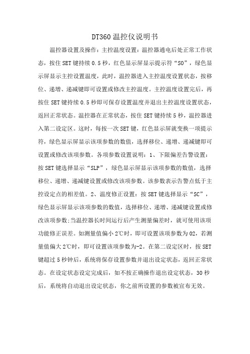
DT360温控仪说明书
DT360温控仪说明书
温控器设置及操作:主控温度设置:温控器通电后处正常工作状态,按住SET键持续0.5秒,红色显示屏显示提示符“SO”,绿色显示屏显示主控设置温度,此时,温控器进入主控温度设置状态,按移位、递增、递减键即可设置或修改主控温度。
主控温度设置完后,再按住SET键持续0.5秒即可保存设置温度并退出主控温度设置状态,返回正常状态。
温控器在正常状态,按住SET键持续5秒,温控器进入第二设定区。
这时,每按一次SET键,红色显示屏就变换一项提示符,绿色显示屏显示该项参数的数值,选择移位、递增、递减键即可设置或修改该项参数。
各项参数设置说明:1、下限偏差告警设置:按SET键选择显示“SLP”,绿色显示屏显示该项参数的数值,选择移位、递增、递减键设置或修改该项参数。
该参数表示告警点低于主控设定点的相差值。
2、温度修正设置:按SET键选择显示“SC”,绿色显示屏显示该项参数的数值,选择移位、递增、递减键设置或修改该项参数;当温控器长时间运行后产生测量偏差时,就可使用该项功能修正误差。
如测量值偏小2℃时,即可设置该项参数为02,若测量值偏大2℃时,即可设置该项参数为-2。
在第二设定区时,按SET 键超过5秒钟后,系统将保存设置参数并退出设定状态,返回正常状态。
在设定状态设定完成后,如不按正确操作退出设定状态,30秒后,系统将自动退出设定状态,你之前所设置的参数被宣布无效。
DT8807H使用说明书
DT8807H使用说明书
DT8807H专业高温红外线测温仪具有高温及远距离非接触测量的特点,测温范围-50~1650℃,小于150毫秒的快速响应时间,双激光指示可以方便地瞄准目标并更为精准地测量温度,适用于冶炼铸造炉温测试等工业物体测温。
①握住仪表手柄并使其红外线传感器,指向被测物体表面。
②扣动扳机以开机测量,如果电量充足,显示器会亮,若不亮或电池能量不足,请更换电池。
③测量时,"SCAN',提示将出现在液晶显示屏的左上方。
④继续扣动扳机:a.当开机时激光会跟随打开,如果不用激光瞄准时,按下激光按钮则可关闭它,再次按下又可打开。
当激光打开时,激光提示将出现在液晶显示器上的温度上方。
将红色激光束瞄准被测物体。
b.用℃/ ℉按钮选择温度单位
c.用Max/Min按钮可进入*大值或*小值测量模式,
d.按下背光灯按键打开液晶显示屏的背光灯功能。
⑤放开扳机,HOLD提示出现在液晶显示屏上,表明读数已被保持放开扳机大约10秒后仪表将自动关机。
测量1000℃的手持式红外测温仪DT-1000使用说明

DT-1000手持式红外测温仪说明书一、介绍DT-1000型红外测温仪通过测量物体表面辐射的红外能量来确定物体的表面温度,适用于快速测量各种高温、有毒或难于接触的物体表面温度。
本机由光学系统、光电传感器、信号放大器、信号处理电路及LCD显示等部分组成。
光学系统汇聚物体表面辐射的红外能量到光电传感器,由光电传感器将能量转换成相应的电信号,该信号经过信号放大器和信号处理电路转化为读数显示在LCD上。
二、安全须知1、警告:为避免对用户可能造成的伤害,请阅读并遵照下列指导:在使用本机时请不要将激光直接对准眼睛或通过反射性表面间接射向眼睛。
本仪器不能透过透明表面进行测量,如:玻璃/塑料等,否则本仪器测得数值将会是该透明物体的表面温度。
蒸汽/灰尘/烟或其它粒子会对仪器镜片形成障碍,影响测量的准确性。
2、注意:为避免损坏测温仪或被测设备,请保护它们免受以下影响:弧焊机和感应加热器等产生的EMF(电磁磁场)。
热冲击(由于环境温度产生较大或突然改变引起,在使用前要等待30分钟使测温仪达到稳定状态)。
切勿将测温仪靠近或放在高温物体上。
三、物距比D:S1、使用本机测量温度时,要注意考虑距离与测量区域大小之间的比率(简称物距比)。
当本机与被测物体的距离增大时,测量区域也会相应增大。
本测温仪物距比为20:1(如图1)本机配有定位激光用于瞄准被测物体表面2、观测范围:一定要确保被测目标要大过本机的测量区域。
当被测目标越小时与被测目标的距离应越近;要进行精确测量时,要保证被测目标至少比测量区域大过一倍以上。
四、发射率大多数有机材料及油漆或氧化材料的发射率为0.95(已预设在本机中),光滑或打磨的金属表面可能会导致测量值的不准,解决方法是调整仪器的发射率读数(详见发射率表)。
或用遮盖胶带或黑色油漆盖住测定表面,并等待之与下面的材料的温度一样,然后再进行温度的测量。
物质发射率物质发射率铝0.30铁0.70石棉0.95铅0.50沥青0.95石灰石0.98玄武岩0.70油0.94黄铜0.50油漆0.93砖0.90纸0.95碳0.85塑料0.95陶瓷0.95橡胶0.95混凝土0.95砂0.90铜0.95皮肤0.98油泥0.94雪0.90冷冻食品0.90钢0.80热食品0.93织品0.94玻璃(板)0.85水0.93冰0.98木0.94五、操作说明1、快速测量:A、打开电池门,装入9V电池;B、扣动扳机开机;C、通过定位激光瞄准被测物体表面(如不需激光定位,可关掉),扣动扳机目标温度就会显示在LCD上,松开扳机后,温度将保持显示在LCD上。
DeltaTrak DT-8806H 无接触头部红外体温计说明书

P .O. Box 398 Pleasanton, CA 94566 USA | p (925)249-2250 | (800)962-6776 | f (925)249-2251 | • Mediciones precisas de temperatura de la frente sin contacto • Garantizado para 40,000 mediciones • ° Celsius o ° Fahrenheit Seleccionables • Detección de calor en la frente• Cuerpo seleccionable o modos de superficie • Configuraciones de alarma• La memoria contiene 32 puntos de datos de temperatura.• Retención automática de datos • Apagado automático• Rango de selección automática • Resolución de Pantalla 0.1°C (0.1°F)• Pantalla LCD de Retroiluminación • Certificaciones: FDA, CE, FCCDT-8806H Non-Contact Forehead Infrared Thermometer (Termómetro infrarrojo de frente sin contacto)Alcance (Modo Cuerpo)32.0ºC a 42.5ºC/89.6ºF a 108.5ºF Rango (Modo de Superficie)0ºC a 60ºC/32ºF a 140ºF Resolución de Pantalla 0.1ºC/0.1ºFTemperatura de Funcionamiento 10ºC a 40ºC (50ºF a 104ºF)Temperatura de Almacenamiento 0ºC a 50ºC (32ºF a 122ºF)Tasa de Humedad ≤ 85%Precisión delTermómetro IR del Cuerpo sin contacto ASTM E1965-1998 (2003)32ºC a 35.9ºC/93.2ºF a 96.6ºF (±0.3ºC/±0.5ºF)36ºC a 39ºC/96.8ºF a 102.2ºF (±0.2ºC/±0.4ºF)39ºC a 42.5ºC/102.2ºF a 108.5ºF (±0.3ºC/±0.5ºF)Distancia de Medición 5cm-15cm (1.97in- 5.9in)Parada Automática 0.5 SegundosConformidad de SeguridadEN 12470-5: Norma Europea para Termómetro Clínico Rendimiento - Termómetros de Oído Infrarrojo ASTM E1965-1998: ASTM (Sociedad Americana de Pruebas y Metodología) Especificación estándar de termómetros infrarrojos para determinación intermitente de la temperatura del pacienteEN 980: símbolos gráficos para usar en el etiquetado de dispositivos médicosEN 1041: Información suministrada por el fabricante. con dispositivos médicosEN 60601-1: Equipo eléctrico médico Parte 1: Requisitos generales de seguridad (IEC: 60601-1:1998)EN 60601-1-2: Equipo eléctrico médico Parte 1-2:Requisitos generales de seguridad - Estándar de garantía: Compatibilidad electromagnética - Requisitos y pruebas (IEC 60601-1-2:2001)Batería DC 3V (2 pilas AA de 1.5v)Tamaño 149 mm x 77 mm x 43 mm (5,9 x 3 x 1,7 pulgadas (largo x ancho x alto)PesoBruto: 0.88lbs / 400gr Neto: 0.38lbs / 172grSS 15004_Sp_20D1Los Termómetros de Temperatura Infrarroja en la frente aseguran lecturas precisas y estables de la temperatura corporal.Desde una distancia de 5 cm (2 pulgadas), simplemente apunte el dispositivo a la frente y lea la temperatura que se muestra en la pantalla LCD.La temperatura del cuerpo humano varía a lo largo deldía. También puede ser influenciado por numerosos factoresexternos. Factores: edad, género, tipo y grosor de la piel.El paquete incluye:•Modelo 15004 Termómetro IR • 2 pilas AA de 1,5 V •Manual del usuarioUso previstoEl Non-Contact Forehead IR Thermometer (Termómetro IR de frente sin contacto) está diseñado para la medición de la temperatura de la frente. El termómetro IR de frente sin contacto también se puede utilizar para medir latemperatura de los objetos mediante la función Temperatura de superficie.Alarma BUZZER-FEVERDespués de la medición, enviará un sonido continuo de pitido para informarle de la temperatura corporal anormal si está más allá del rango establecido (La alarma predeterminada es de 38ºC que puede ser establecida por el usuario).。
DTK 系列溫度控制器操作手冊说明书
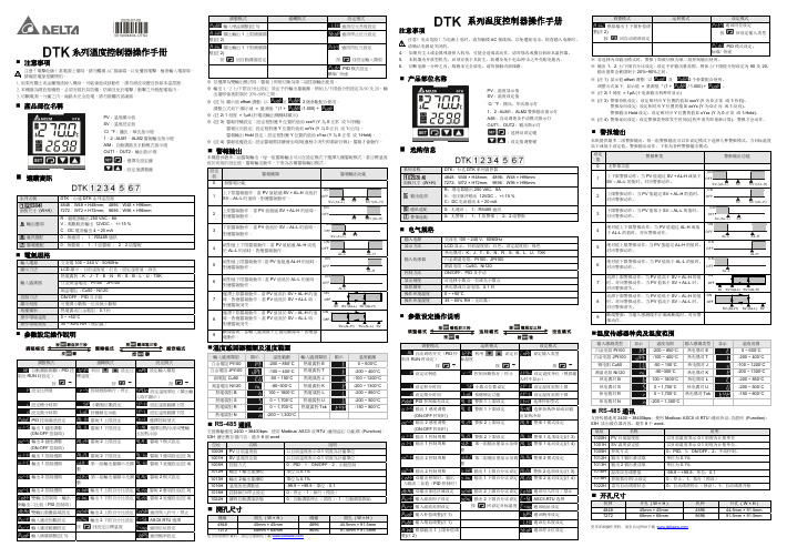
系列溫度控制器操作手冊注意事項注意!電擊危險!當電源上電時,請勿觸摸AC 接線端,以免遭致電擊。
檢查輸入電源時,請確認電源是關閉的。
1. 如果有塵土或金屬殘渣掉入機身,可能會造成誤動作。
請勿修改或擅自拆卸本溫控器。
2. 本機器為開放型機殼,必須安裝於具防塵、防潮及免於電擊∕衝擊之外殼配電箱內。
3. 切斷電源一分鐘之內,線路未完全放電,請勿接觸內部線路。
產品部位名稱PV : 溫度顯示值 SV : 溫度設定值˚C/ °F : 攝氏、華氏指示燈1、2 : ALM1、ALM2警報輸出指示燈 A/M : 自動調諧及手動模式指示燈 OUT1、OUT2 : 輸出指示燈: 選擇及設定鍵: 設定值調整鍵選購資訊系列名稱 DTK :台達DTK 系列溫控器面板尺寸 (W×H)4848:W48 × H48mm; 4896:W48 × H96mm 7272:W72 × H72mm; 9696:W96 × H96mm 輸出選項 R :繼電器輸出250 VAC ,8AV :電壓脈波輸出 12VDC , +/-15 % C :DC 電流輸出4 ~ 20 mA通訊選配0:無通訊 ; 1:RS485通訊警報選配0:無警報 ; 1:1組警報 ; 2:2組警報電氣規格輸入電源交流電100 ~ 240 V ,50/60Hz顯示方法 LCD 顯示。
目前溫度值:紅色,設定溫度值:綠色輸入感測器熱電偶對:K 、J 、T 、E 、N 、R 、S 、B 、L 、U 、TXK白金測溫電阻:Pt100、JPt100 測溫電阻 : Cu50、Ni120控制方法 ON/OFF 、PID 及手動顯示刻度可選擇小數點一位或無小數點取樣頻率熱電偶或白金電阻:0.1秒操作環境溫度0 ~ +50°C操作環境溼度35 ~ 80% RH (無結露)參數設定操作說明調整模式 運轉模式設定模式自動調諧開關(PID 控制及RUN 時設定)按♦利用設定目標溫度按♦設定輸入類型按♦設定比例值控制迴路執行∕停止 設定溫度單位(類比輸入時不顯示)設定積分時間 小數點位數設定 設定溫度範圍上限 設定微分時間 按鍵鎖定功能 設定溫度範圍下限PID 控制偏差設定 警報1上限設定 選擇控制型式 輸出1感度調整 (ON-OFF 控制時) 警報1下限設定 選擇加熱⁄冷卻或雙輸 出加熱冷卻輸出2感度調整 (ON-OFF 控制時) 警報2上限設定 警報1模式設定 輸出1控制週期 警報2下限設定 警報1選項設定(註3) 輸出1控制週期第一組輸出量顯示及調 整警報1延遲設定(註4) 輸出2控制週期第二組輸出量顯示及調整警報2模式設定 輸出2控制週期 輸出1上限百分比設定 警報2選項設定(註3) 雙輸出控制時,輸出一與輸出二比值(PID 控制時)輸出1下限百分比設定警報2延遲設定(註4)雙輸出重疊區域設定 輸出2上限百分比設定 通訊寫入許可∕禁止 輸入濾波因數設定 輸出2下限百分比設定 按 回設定目標溫度ASCII,RTU 選擇 輸入濾波範圍設定 通訊位址設定 輸入補償調整(註1)通訊鮑率設定調整模式 運轉模式設定模式 輸入增益調整(註1)通訊位元長度設定 類比輸出1上限補償調整(註2)通訊停止位元設定 類比輸出1下限補償調整(註2)按 回自動調諧設定通訊同位元設定按回設定輸入類型PID 模式設定,標準/ 快速※ 若選擇為雙輸出模式時,警報1即被切換為第二組控制輸出使用。
无线测温说明书

DT-WMT型无线测温装置产品手册目录一、概述 (2)二、无线测温装置构造 (2)1. 无线测温显示仪 (2)〔1〕功能与特点 (2)〔2〕性能指标 (2)〔3〕按键功能 (3)〔4〕操作说明 (3)〔5〕产品尺寸及安装 (9)〔6〕产品端子功能对照接线图 (11)〔7〕通讯 (12)2. 无线测温传感器 (13)〔1〕工作原理 (13)〔2〕性能指标 (13)〔3〕传感器封装型式及外型 (14)〔4〕传感器的安装 (14)〔5〕传感器的寿命 (15)三、运输与贮存 (15)四、保修及维护 (15)五、订货须知 (16)一、概述电力系统正向着大电网高可靠性、高自动化程度的方向迅猛开展。
对电网运行自动化、智能化的监控程度已成为国内外高度重视的关键问题。
随着社会用电量的日益增加,高压开关、GIS〔气体绝缘变电站〕等高压电器和载流母线等电力设备在负载电流过大时会出现温升过高,最后能使相邻的带电部件性能劣化,甚至击穿,根据电力平安监视部门提供数据分析,全国电力单位每年因为高压开关、母线温度过高引发的重大事故上千起,给消费和经营造成宏大经济损失。
因此,电力系统不惜人力、财力,采取多种措施监测高压联接点的温升。
目前国内专门用于高压母线、高压开关及电接触发热测量的仪器还很少。
温度监测的方法,一种是在高压电接触外表涂一层颜色随温度变化的发光材料,通过观察其颜色变化来大致确定温度范围,这种方法准确度低、可靠性差,不能进展定量测量;一种方法是利用辐射特性的红外热像仪,准确度较高,但由于需要光学器件,在高压开关柜等特定场合使用不太方便,而且价格较高,推广应用有一定困难。
另外一种是采用光导纤维传输温度信号,光导纤维具有优异的绝缘性能,可以隔分开关柜内的高压,因此光纤温度传感器可以直接安装到开关柜内的高压触点上,准确测量高压触点的运行温度,实现开关柜触点运行温度的在线监测。
然而,用于隔离高压的光纤外表可能受到污染,将导致光纤沿面放电。
和erson DTG温度指示器说明书
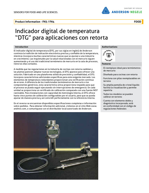
SENSORS FOR FOOD AND LIFE SCIENCES.Indicador digital de temperatura “DTG” para aplicaciones con retortaIntroductionEl indicador digital de temperatura (DTG, por sus siglas en inglés) de Anderson continúa la tradición de indicación electrónica precisa y confiable de la temperatura, mientras incorpora muchas características nuevas que se ajustan a una industriaen crecimiento. Las inquietudes por la salud relacionadas con el mercurio siguen aumentando y el uso del tradicional termómetro de mercurio en la sala de procesos, tiene los días contados.A medida que las regulaciones en la industria de cocinas con retorta cambian ylas plantas parecen adoptar nuevas tecnologías, el DTG aparece para ofrecer una solución. Fabricado en una plataforma sólida de precisión y confiabilidad, el DTG incorpora características adicionales específicas para este exigente mercado. Los elementos de temperatura redundantes proporcionan una verificación continuade errores. A diferencia de los tradicionales termómetros de mercurio o los componentes genéricos, esta característica única proporciona respaldo para queel proceso se pueda seguir ejecutando sin interrupciones de emergencia. En cada unidad se proporciona un certificado de calibración comparado con una fuente NIST rastreable. Para instalaciones con capacidad de metrología interna, el DTG ofrece hasta cinco puntos de calibración configurables por el usuario, para que se pueda ajustar de manera precisa y así coincidir perfectamente con la referencia interna.En el reverso se encuentran disponibles especificaciones completas e información sobre pedidos. Para obtener información adicional, visítenos en el sitio Web www., o comuníquese con el distribuidor local autorizado de Anderson.205052S / 2.0 / 2015-03-20 / GR / MX ANDERSON INSTRUMENT COMPANY 156 Auriesville Road Fultonville, NY 12072Phone 800-833-0081Fax 518-922-8997************************Tech. Support:*******************************Phone 800-833-0081TIPO 3 Retorta de alta temperatura - Montaje directo 4R etorta de alta temperatura - Pantalla remota (debe pedir el tipo de montaje 9)UNIDADES DE LA PANTALLA 0 Grados F 1Grados CMONTAJE 1 Parte inferior4 Parte posterior (codo en 90°)5 Izquierda6 Derecha7 Parte superior8 Parte posterior (codo en 45°)9Pantalla remota - Salida del cable inferiorAJUSTES/INSERCIÓN 100-049 Pozo tipo proyectil* 3-1/2 pulg.101-091 Pozo tipo proyectil* 6-1/8 pulg.062-139 Pozo tipo proyectil 9-1/8 pulg.063-161 Pozo tipo proyectil 10-1/2 pulg.064-187 Pozo tipo proyectil 12-1/8 pulg.084-033 Pozo bimetálico NPT de 1/2 pulg. 2-1/2 pulg.084-057 Pozo bimetálico NPT de 1/2 pulg. 4 pulg.084-089 Pozo bimetálico NPT de 1/2 pulg. 6 pulg.084-137 Pozo bimetálico NPT de 1/2 pulg. 9 pulg.084-185 Pozo bimetálico NPT de 1/2 pulg. 12 pulg.084-233 Pozo bimetálico NPT de 1/2 pulg. 15 pulg.084-281 Pozo bimetálico NPT de 1/2 pulg. 18 pulg.084-377Pozo bimetálico NPT de 1/2 pulg.24 pulg.LONGITUD DEL CABLE DE LA PANTALLA REMOTA 0 Ninguno1 1,5 m (5 pies) (tipo 4)23 m (10 pies) (tipo 4)3 4,6 m (15 pies) (tipo 4)46,1 m (20 pies) (tipo 4)CARACTERES FIJOSSONDA 0Sonda estándarF H1-1/4 pulg. 18 UNEFTuerca IAMD Pozo industrial00Comuníquese con el fabricante para conocer otros ajustes.* Sondas de reemplazo de termómetros de mercurio típicos.45°1456789Montaje。
温度测量仪DTC-300的设置指南说明书
Thermal Conductivity InstrumentsDTC-300Site Preparation GuideTable of ContentsTable of Contents (1)Ideal Setup ................................................................................................................................... 2-3 System Components .. (3)Instrument Measurements (4)Utility Requirements (5)Power (5)Gas (6)Coolant (7)Water (8)Computer Requirements (9)Site Preparation Checklist (10)TA Instrument Offices (11)Ideal SetupIDEAL PLACEMENT AND BENCH MEASUREMENTSSelect a location with adequate floor space and a rigid laboratory bench that is level and is in a vibration-free environment.Bench length: 1.8 m (6 ft)Bench depth: 76 cm (30 in)Ideal Setup and ComponentsCOMPONENTSPlace the chiller on the same level as the instrument.A. ChillerB. InstrumentC. Computer (Controller)ABCInstrument Measurements INSTRUMENT MEASUREMENTSWidth: 64 cm (25 in)Depth: 71 cm (28 in)Height: 94 cm (37 in)Weight: 44 kg (98 lbs)POWERInstrument∙100–120 VAC, 10 A, 60 Hz (US)∙200–240 VAC, 10 A, 50/60 Hz (Non-US)∙Installation of a 16A Class B or C main fuse is recommended.Power cords providedUse power cords with plugs appropriate for your circuit.∙NEMA 5-15 plug for 100–120 VACOR∙NEMA 6-15 plug for 200–240 VACNEMA 6-15 plug NEMA 5-15 plugSupply voltages lower than indicated may result in a degradation of performance.Ensure that the mains assigned do not also supply power to noise generating equipment nearby, such as motors, welders, transformers, etc.An independent heavy GROUND wire must be provided through the power hookup. Improper grounding may cause severe damage for which the supplier will not accept responsibility. All power strips must be fully grounded and carry the ground through to the sockets into which the computer is plugged.GASPneumatic RamGas Requirements for Pneumatic Ram Type Must be nitrogen or airSource Must be from a gas cylinder, Grade 5 purityInlet Pressure Minimum: 40 psig (2.75 bar) Maximum: 50 psig (3.45 bar)Tubing ∙¼” tubing is supplied to connect f rom instrument to gas regulator∙Tubing is rated to 100 psig (7 bar)Purge GasGas Requirements for PurgeType Must be nitrogen; at sub-ambient temperatures to prevent frost and moisture buildup on internal metal componentsInlet Pressure Less than 5 psig needed–it is simply a low, steady flow to flush the furnace cavityTubing∙Purge gas port requires 1/8” tubing (provided)∙ A 1/8” stem to ¼” tubing adapter is also providedThe customer is required to supply either compressed air, dried and filtered, to 10 microns, or laboratory grade inert gas (such as nitrogen from a high pressure cylinder).COOLANTRequirementsPressure 4.3 psig (0.30 bar) maximumFlow Rate 20 L/min (5 gal/min) maximumOperating close to or below min. pressure will result inerratic operation.Cooling Capacity ∙At -20°C = 265W ∙At 0°C = 650W∙At +20°C = 1000WCoolant Liquid ∙50/50 mix of DI water and laboratory grade ethylene glycol for testing up to 300°C∙Denaturalized alcohol for sub-zero testingConnections Supplied: Two hoses (6 feet / 1.8 meters each) to connect to the Coolant Inlet and Outlet ports on the back of the furnace. The other end of each hose is blank; a male 3/8” barb with ¼” threads (provided) must be installed to connect to the coolant source.Place the chiller on the same level as the P/N 202612.001 (120V for 60Hz power) or202442.001 (240V for 50Hz power)Coolant Inlet and Outlet ports and hosesWATERExcessively cold water will result in “sweating” and corrosion of cooled metal surfaces. The purge of nitrogen gas through the furnace will prevent this.Operating below the minimum chiller coolant level will result in erratic operation. A chiller/circulator is recommended for this instrument.If a chiller/circulator is to be used, it must be placed at the same level as the instrument.Computer RequirementsHARDWARE REQUIREMENTS∙Unused RS-232 (serial) port∙Unused USB portInstrument drivers and software are provided on a CD.Computer should not be attached to other analytical instruments or LAN.SOFTWARE REQUIREMENTSItem RequirementOperatingSystem∙Windows 7 or 10, 32- or 64-bit, Ultimate, Enterprise & Professional∙Home version not supportedNetwork∙TA Instruments is not responsible for resolving issues associated withconnections to your corporate network.∙Network cards and/or certain network operation frequently interferewith the operation of the instrument and software.ConflictsTA Instruments is not responsible for resolving hardware/software conflictscreated by the addition of third party hardware or software to thecomputer.Site Preparation ChecklistThermal Conductivity Instruments: DTC-300 Sufficient bench space for instrument, computer, and chiller (if needed): ☐ Length: 1.8 m (6 ft)☐ Depth: 76 cm (30 in)Instrument power is☐ 100–120 VAC, 10 A max, 60 Hz (US)☐ 220–240 VAC, 10 A max, 50/60 Hz (Non-US)Computer, monitor, and chiller power is☐ 120 V (US)☐ 220–240 V, 6.4 A max, 50/60 Hz (Non-US)Pneumatic Ram Gas – Air or Nitrogen☐ Regulator to allow 40–50 psig (2.75–5.50 bar)Purge Gas – Dry Nitrogen☐ Under 5 psig (2.75–5.50 bar)Water Circulation☐ Nominal flow rate of 20 L/minute (5 gal/min)☐ Maximum pressure of 4.3 psig (0.30 bar)☐ Sufficient cooling capacity ☐ 50/50 mix of DI water and laboratory grade ethylene glycol (for temperatures up to 300°C)☐ Denaturalized alcohol (for sub-zero measurements) I hereby acknowledge that all utility requirements have been met per the checklist above and that they will be ready at the agreed time of installation.If all utility requirements are not met at the agreed time of installation, additional charges may be incurred for a return Service trip.CustomerDD MM YYYY CompanyCity State CountryPlease send a signed copy of the completed checklist to your local Service representative.TA Instruments Offices For information on our latest products, contact information, and more, see our website at: .To find your local TA Instruments office and contact information, visit/contact/ta-directory/TA Instruments – Waters LLCCorporate Headquarters159 Lukens DriveNew Castle, DE 19720USATelephone: 302-427-4000Fax: 302-427-4001Email: **********************。
DT-8835工业用非接触式红外线测温仪使用说明书答辩

成都华衡仪器有限公司 -------------------------------------------------------------------------------------------------------DT-8835非接触式红外线测温仪使用说明书成都华衡仪器有限公司DT-8835非接触式红外线测温仪DT-8835非接触式红外线测温仪简介 :售价:800.00/个(不含税和运费DT-8835系列红外 +K型热电偶二合一红外线测温仪具有多功能、经济实惠、精准耐用等特点。
本型号温度范围最高可达 1050℃,距离比高达 30:1,让您在测温工作中拥有更多的选择余地,同时备受青睐的高性价比实为您的明智之选。
商品毛重:0.894kg环境测试类:非人体测温仪商品产地:中国大陆DT-8835非接触式红外线测温仪产品特色:1. 非接触式精确测温及 K 型温度测量2. 带背光源 LCD 显示屏及独特的外观设计3. 自动选择量程、自动数值保持及自动关机4. ℃ /℉转换按键及扳机锁5. 内置激光瞄准器及最大、最小数值记录6. 发射率可调整从 0.10到 1.07. 分辨率为 0.1℃ /℉8. 可设置最高 /最低温报警9. 距离与物体目标比 D:S=30:1DT-8835非接触式红外线测温仪产产品结构图:1. 液晶显示屏2. 激光 /背光按键 /设置键3. 向上键4. 模式键 MODE5. 向下键6. 激光瞄准器7. 红外线传感器8. 测量扳机9. 电池盖 /其他调节键1. ℃ /℉转换键2.ON/OFF 锁定键3. 高低温警报开关键DT-8835非接触式红外线测温仪产品主要功能:【 K 型热电偶测温】量程:-50~1370℃(-58~2498℉分辨率:0.1℃【红外线测温】量程:-50~1050℃(-58~1922℉距离比 (D:S:30:1 分辨率:0.1℃响应时间:小于 1秒光谱响应:8~14um 发射率:可调 0.10~1.0 采样速率:2.5次 /秒超出量程提示:显示器上显示“ -OL” , “OL”极性:自动(正极无显示;减号(-表明负极激光管:发射功率小于 1Mw, 波长 630~670nm,二级激光产品操作温度:0~50℃储存温度:-20~60℃相对湿度:10~90%RH(操作, <80%RH(存储电源:9V 电池。
dt1311说明书
dt1311说明书
1、原理及构造
该温度计由感温部、导管部及显示部构成,感温筒内充满了低温挥发性液体和其蒸汽。
感温部周围的温度发生变化时,低温挥发性液体的饱和蒸汽压发生变化,经过导管,使波顿管内部的压力也发生变化。
这个波顿管的变位通过传导构造及放大装置,等变位地放大、由指针在刻度板上显示出温度来。
指示部由指针和接点针接触,配置了一个或者两个使回路关闭的电接点回路,配有和温度的上升一同上升,温度下降时仍停留在原位,可以表示出最高温度的手动复原式的最高指针。
此温度计由感温部、导管部及显示部构成,感温筒、导管、波顿管内充满了有机液体。
感温部周围发生温度变化时,感温筒内的液体膨胀、收缩,其压力的变化经过导管传达到波顿管内部。
波顿管由于其内部压力的变化发生变位,直接由指针在刻度板上标示出温度来。
波顿管端部和指针一起安装了凸轮,配置了一个由这个凸轮启动微动开关形式的电接点回路。
2、使用说明
温度计内部充满液体或瓦斯,如果导管部分断裂,感温部分出现裂口等,内部的液体和瓦斯会泄露,使计量器无法工作。
另外标示部分由精密零件所构成,如果受到异常的震动及冲击,标示内容将发生误差,甚至造成温度计的破损,应该给予充分的主意。
在搬运温度计
时,一定要把温度计整体一起拿起来进行搬运。
搬运时,如果导管下垂脱拽,或者手提导管实显示部处于下吊状态,都是绝对要避免的。
DT1000 I4 Pt100 温度传输器操作指南说明书

DT1000 I4 Pt100 Temperature TransmitterOperating InstructionsDT1000 I4 Contents1. About this document1.1. Function (4)1.2. Target group (4)1.3. Symbolism used (4)2. For your safety2.1. Authorized personnel (5)2.2. Appropriate use (5)2.3. Warning about misuse (5)2.4. General safety instructions (5)2.5. CE conformity (5)2.6. Environmental instructions (5)3. Product description3.1. Delivery configuration (6)3.2. Principle of operation (6)3.3. Adjustment (7)3.4. Storage and transport (7)4. Mounting4.1. General instructions (8)4.2. Main dimensions of the instrument (8)4.3. Mounting procedure (9)5. Connecting5.1. Preparing the connection (10)5.2. Connecting the Pt100 sensor (11)5.3. Connecting the signal processing unit and the power supply12 5.4. Put the instrument under supply voltage (12)DT1000 I46. Fault rectification6.1. Fault finding (13)6.2. Repairing (13)7. Dismounting7.1. Dismounting procedure (14)7.2. Disposal (14)8. Appendix8.1. Technical specification (15)8.2. Application example (17)DT1000 I41. About this document1.1. FunctionThis operating instructions manual has all the information you need for quick set-up and safe operation ofDT1000 I4 Temperature Transmitter.Please read this manual before you start setup.1.2. Target groupThis operating instructions manual is directed to trained personnel. The contents of this manual should be made available to these personnel and put into practice by them.1.3. Symbolism usedInformation, tip, noteThis symbol indicates helpful additional information.Caution, warning, dangerThis symbol informs you of a dangerous situation that couldoccur. Ignoring this cautionary note can impair the personand/or the instrument.•ListThe dot set in front indicates a list with no implied sequence.→ActionThis arrow indicates a single action.1SequenceNumbers set in front indicate successive steps in aprocedure.DT1000 I42. For your safety2.1. Authorized personnelAll operations described in this operating instructions manual must be carried out only by trained and authorized specialist personnel. For safety and warranty reasons, any internal work on the instruments must be carried out only by DATCON personnel.2.2. Appropriate useThe DT1000 I4 is a temperature transmitter. Detailed information on the application range is available in Chapter 3.Product description.2.3. Warning about misuseInappropriate or incorrect use of the instrument can give rise to application-specific hazards, or damage to system components through incorrect mounting or adjustment.2.4. General safety instructionsThe DT1000 I4 Temperature Transmitter is a high-tech instrument requiring the strict observance of standard regulations and guidelines.The user must take note of the safety instructions in this operating instructions manual, the country-specific installation standards as well as all prevailing safety regulations and accident prevention rules.2.5. CE conformityThe DT1000 I4 is in conformity with the provisions of the following standard:EN 61326:2004 (EMC)2.6. Environmental instructionsProtection of the environment is one of our most important duties.Please take note of the instructions written in the following chapters:• Chapter 3.4. Storage and transport• Chapter 7.2. DisposalDT1000 I43. Product description3.1. Delivery configurationDelivered items The scope of delivery encompasses:• DT1000 I4• documentation:this operating instructions manualcertificationwarranty3.2. Principle of operationArea of application A DT1000 I4 Temperature Transmitter provide a 4-20 mAsignal in proportional to the temperature measured by thePt100 temperature sensor connected to their input.The instrument is loop-powered from 4-20 mA signal.The sensor element can be connected in 3 or 4 wiremeasuring mode. In case of connecting the Pt100 in 4 wiremode the wire and the connecting resistances have noeffect on the measurement. In case of 3 wire mode theinstrument is able to compensate the effect of the wire andconnecting resistances if the PI+ and PI- resistances(wire+connecting) are equal to each other.The measuring current is about 800 μA, so the self-heatingeffect of the sensor is negligible.In case of input fault (sensor or wire, short or broken) theoutput current is forced under 3.8 mA.There are recommended measuring ranges, see8.1. Technical specification, however customer specifiedranges also available.Input and output is not isolated.Operating principleThe instrument supplies measuring current for the Pt100 sensor through the PI+, PI- connectors. The voltage drop on the sensor is led through the Pt+, Pt- connectors, filter-, protective- circuits to the amplifier and linearizing stage. The output of this stage controls the 4-20 mA output current according to the measuring range.The supply voltages and the reference voltages are generated from the 4-20 mA current loop.Power supply The instrument works from a 10-30 VDC supply voltage.The maximum supply current is 25 mA.DT1000 I43.3. AdjustmentThe DT1000 I4 doesn’t need any adjustment.After connected to the power supply it is ready to work.3.4. Storage and transportThis instrument should be stored and transport in places whose climatic conditions are in accordance with chapter 8.1 Technical specification, as described under the title: Environmental conditions.The packaging of DT1000 I4 consist of environment-friendly, recyclable cardboard is used to protect the instrument against the impacts of normal stresses occurring during transportation. The corrugated cardboard box is made from environment-friendly, recyclable paper. The inner protective material is nylon, which should be disposed of via specialized recycling companies.DT1000 I44. Mounting4.1. General instructionsThe instrument should be installed in a cabinet withsufficient IP protection, where the operating conditions arein accordance with chapter 8.1 Technical specification, asdescribed under the title: Operating conditions.Mounting positionThe instruments are designed in housing for mounting onTS-35 rail.It is recommended to mount it in vertical position (horizontalrail position).4.2. Main dimensions of the instrumentDT1000 I44.3. Mounting procedureThe following figure shows the mounting procedures (fixingon the rail):Mounting on the railThe mounting doesn’t need any tool.1. Tilt the instrument according to the figure; put theinstrument’s mounting hole onto the upper edge of the rail (figure step 1.).2. Push the instrument’s bottom onto the bottom edge of the rail (figure step 2.), you will hear the fixing assembly closing.3. Check the hold of the fixing by moving the instrument firmly.DT1000 I45. Connecting5.1. Preparing the connectionSelect connection cablePreparing cablesAlways observe the following safety instructions:• Use only a screwdriver with appropriate headTake note the suitability of the connecting cable(wire cross-section, insulation, etc.).The wire cross-section should be 0.25-1.5 mm2.You may use either solid conductor or flexible conductor.In case of using flexible conductor use crimped wire end. Prepare the cable for connection.Strip approx. 8 mm insulation.It is recommended to use screened cable especially for sensor connecting. In particular, make sure that no potential equalization currents flow over the cable screen. Ground the cable screen on the cabinet side.It is an important rule that the measuring signal cables should be lead via a separate way than the control and power cables.DT1000 I45.2. Connecting the Pt100 sensor The following figure shows the wiring plan, connecting thePt100 sensor:Wiring plan, connecting the Pt100 sensor in 4 wire mode(see also “Application example”)Wiring plan, connecting the Pt100 sensor in 3 wire mode(see also “Application example”)1. Loosen terminal screws.2. Insert the wire ends into the open terminals according to the wiring plan.3. Screw the terminal in.4. Check the hold of the wires in terminals by pulling on them firmly.DT1000 I45.3. Connecting the signal processing unit and the power supplyThe following figure shows the wiring plan, connecting thesignal processing unit:Wiring plan, connecting the signal processing unit and the power supply(see also “Application example”)Be careful the polarity of the cablesChecking the connections1. Loosen terminal screws.2. Insert the wire ends into the open terminals according to the wiring plan.3. Screw the terminal in.4. Check the hold of the wires in terminals by pulling on them firmly.Check if the cables are connected properly (have you connected all the cables, have you connected to the right place, do not the cable-ends touch each other). The connection is finished.5.4. Put the instrument under supply voltage Put the instrument under supply voltageAfter you have completed the connections, put theinstrument under supply voltage. If the connection is correct you can measure output current according to the measured temperature.DT1000 I46. Fault rectification6.1. Fault findingThe fault finding must be carried out by trained and authorized personnel only.• There is no output signal → check the power supply.If the power supply is OK, the instrument is defective. • The output current < 3.8 mA → check the Pt100 sensor and it’s connecting. If the Pt100 sensor and it’s connecting is OK, the instrument is defective.When the result of fault finding is that the DT1000 I4 is defective call the manufacturer service department.6.2. RepairingThere is no user repairable part inside the instrument.In accordance with Chapter 2.1.: For safety and warranty reasons, any internal work on the instrument must be carried out by DATCON personnel.DT1000 I47. Dismounting7.1. Dismounting procedureBefore dismounting take note the warnings written in Chapter 5.1.The following figure shows the dismounting procedures:Dismounting from the railThe dismounting procedure needs a screwdriver for slotted screws.Before dismounting disconnect all wires.1. Put the screwdriver end into the fixing assembly’s hole (figure step 1.).2. Lift the screwdriver handle until it possible to open the fixing assembly (figure step 2.).3. Keeping the screwdriver in this position lift the instrument bottom from the bottom edge of the rail (figure step 3.).4. Lift the whole instrument (you may put out thescrewdriver) (figure step 4.), as far as the instrument will be free.7.2. DisposalAccording with the concerning EU directive, themanufacturer undertakes the disposal of the instrument that are manufactured by it and intended to be destroyed.Please deliver it in contamination-free condition to the site of the Manufacturer or to a specialized recycling company.DT1000 I48. Appendix8.1. Technical specificationInput parameters:Input signal: the resistance of Pt100 sensorWiring: four or three wireMeasuring current: 800 μA (at 100 ohm sensor resistance)Power dissipation on Pt100: 0.25 mW (max.)Wire resistance: 100 ohm (max.)Sensor fault signaling (broken or short): Iout < 3.8 mAMeasuring ranges*:Start points (°C)Measuring ranges (°C)50 100 200 400 600 800-200 -200 - -150 -200 - -100 -200 - 0-200 - 200 -200 - 400-200 - 600-100 -100 - -50 -100 -0-100 - 100-100 - 300 -100 - 500-0 0 - 50 0 -100 0 - 200 0 - 400 0 - 600-100 100 - 150 100 - 200100 - 300100 - 500 - -200 200 - 250 200 - 300200 - 400200 - 600 - -300 300 - 350 300 - 400300 - 500- - -400 400 - 450 400 - 500400 - 600- - -500 500 - 550 500 - 600- - - -* Other ranges on customer request are also availableOutput parameters:Output signal: 4-20 mAOverloading: >22mAError: < 0.2 °C + 10 μA (Ta: 23 °C ±2 °C)< 0.6 °C + 50 μA (Ta: 0-60 °C)Linearizing error: 0.1 °C (0-200 °C)0.3 °C (0-600 °C)Supply-voltage effect: practically zeroPower supply: 10 - 30 VDCCurrent limit: ~ 25 mAAmbient conditions:Operating temperature range: 0-60 °C (-20 - +60 °C on request)Storage temperature range: -20 - +70 °CRelative humidity: 90% (max., non condensing)Place of installation: cabinetDT1000 I4 Electromagnetic compatibility (EMC):Accordance with the standard EN 61326:2004criterionImmunity: -B-Noise emission: -A- classGeneral data:mountinghousing Housing: TS-35railmaterial: polyamide PA6.6terminalConnection: screwConnecting cable: 2.5 mm2 (max.)Dimensions: 12.5 x 99 x 115 mm (width x height x depth)kgWeigh: 0.1520Protection: IPThe Manufacturer maintains the right to change technical data.DT1000 I48.2. Application exampleDT1000 I4DT1000 I4。
海尔电子 DT-5000K 数字温度计说明书
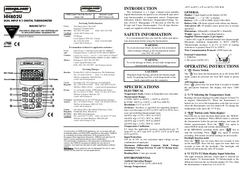
INTRODUCTIONThis instrument is a 5 digit, compact-sized portable digital thermometer designed to use external K-type and J type thermocouples as temperature sensor. Temperature indication follows Reference Temperature/Voltage Ta-bles (N.I.S.T. Monograph 175 Revised to ITS-90) for K-type and J-type thermocouples. Two K-type thermo-couple are supplied with the thermometer.SAFETY INFORMATIONIt is recommended that you read the safety and opera-tion instructions before using the thermometer. WARNINGTo avoid electrical shock, do not use this instrument when working voltages at the measurement surfaceover 24V AC or DC. WARNINGTo avoid damage or burns, do not make temperaturemeasurement in microwave ovens.CAUTIONRepeated sharp flexing can break the thermocouple leads. To prolong lead life, avoid sharp bends in theleads, especially near the connector.SPECIFICATIONSELECTRICALTemperature Scale: Celsius or Fahrenheit user-selectable Measurement Range:J-TYPE -200°C to 1050°C, (-328°F to 1922°F) K-TYPE -200°C to 1370°C, (-328°F to 2498°F) Resolution: 0.1°C or 0.2°FAccuracy:Accuracy is specified for operating tempera-tures over the range of 18°C to 28°C (64°F to 82°F), for 1 year, not including thermocouple error. ±(0.05% rdg + 0.3°C) -50°C to 1370°C ±(0.05% rdg + 0.7°C) -50°C to -200°C ±(0.05% rdg + 0.6°F) -58°F to 2498°F ±(0.05% rdg + 1.4°F) -58°F to -328°F Temperature Coefficient:0.1 times the applicable accuracy specification per °C from 0°C to 18°C and 28°C to 50°C (32°F to 64°F and 82°F to122°F). Input Protection:24V dc or 24V ac rms maximum input voltage on any combination of input pins.Maximum Differential Common Mode Voltage (Maximum Voltage between T1 and T2 during meas-urement): 1volt.Reading Rate: 1 time per second.ENVIRONMENTALAmbient Operating Ranges:0°C to 50°C (32°F to 122°F) <80% R.H. Storage Temperature:-20°C to 60°C (-4°F to 140°F) <70% R.H.GENERALDisplay: 5 digit liquid crystal display (LCD). Overload:“----.-” or “OL” is display.Battery: 1.5V x 4 PCS (SIZE AAA) UM-4 R03.Battery Life: 190 hours typical with carbon zinc battery. Auto power off: 30 minutes, press power key to resume operation.Dimensions: 160mm(H) x 83mm(W) x 38mm(D). Weight: Approx. 265g including batteries. Supplied Thermocouples (2 per input):1 meter (40”) type K insulated beaded wire thermocouple. Maximum insulation temperature is 482°C (900°F). Thermocouple accuracy is ±1.1°C or 0.4% of reading (whichever is greater) from 0°C to 1250°C.Wire Communication Protocol: 19200 baud rate External Connections: 1. USB Port2. DC power JACK(12V)OPERATING INSTRUCTIONS1. “” Power SwitchThe “”key turns the thermometer on or off. In the SET mode cannot be powered off. Exit SET mode to power off.APO function modePress “”power key for more than 6 seconds to disable the auto-power function. The display will show “APO OFF”.2. °C/°F Selecting the Temperature ScaleReadings are dual displayed in either degrees Celsius(°C) or degrees Fahrenheit(°F). When the thermometer is turned on, it is set to the temperature scale that was in use when the thermometer was last turned off. To change the temperature scale, press the °C/°F key.Button (only Main display)annunciator is displayed. When HOLD mode is selected,further measurements. Press the key again toIn the MIN/MAXpress key to stopthe recording. Press keyresume Press the key for more than two seconds to turn seconds to turn off the backlight. The backlight will switch-off automatically after 30 seconds.4. T1 T2/T1-T2 Main display Input SelectionThe input selection indicates which input is selected for main display; T1 thermocouple, T2 thermocouple or the difference between the two thermocouples (T1-T2), whenthe thermometer is turned on, it is set to T1.HH802UDUAL INPUT K/J DIGITAL THERMOMETEROMEGAnetOn-Line Service Internet e-mail **************Servicing North America:U.S.A:One Omega Drive, Box 4047Stamford, CT 06907-0047ISO 9001Tel: (203) 359-1660FAX: (203) 359-7700Certified e-mail:**************Canada:976 BergarLaval (Quebec) H7L 5A1, Canada Tel: (514) 856-6928FAX: (514) 856-6886e-mail:*************For immediate technical or application assistance:U.S.A Sales Service: 1-800-826-6342/1-800-TC-OMEGA ®andCustomer Service: 1-800-622-2378/1-800-622-BEST®Canada:Mexico:En Espan ol: (001) 203-359-7803e-mail:*****************FAX: (001) 203-359-7807**************.mxServicing Europe:Benelux:Postbus 8034, 1180 LA Amstelveen, The Netherlands Tel: +31 (0)20 3472121FAX: +31 (0)20 6434643Toll Free in Benelux: 0800 0993344e-mail:*****************Czech Frystatska 184, 733 01 Karviná, Czech RepublicRepublic:Tel: +420 (0)59 6311899FAX: +420 (0)59 6311114Toll Free: 0800-1-66342e-mail:*****************France:11, rue Jacques Cartier, 78280 Guyancourt, France Tel: +33 (0)1 61 37 2900FAX: +33 (0)1 30 57 5427Toll Free in France: 0800 466 342e-mail:**************Germany/Daimlerstrasse 26, D-75392 Deckenpfronn, Germany Austria:Tel: + 49 (0)7056 9398-0FAX: +49 (0)7056 9398-29TollFreeinGermany************e-mail:*************United One Omega Drive, River Bend Technology Centre Kingdom:Northbank, Irlam, Manchester ISO 9002M44 5BD United KingdomCertifiedTel: +44 (0)161 777 6611FAX: +44 (0)161 777 6622Toll Free in United Kingdom: 0800-488-488e-mail:**************.ukIt is the policy of OMEGA Engineering, Inc. to comply with all worldwide safety and EMC/EMI regulations that apply. OMEGA is constantly pursuing certification of its products to theEuropean New Approach Directives. OMEGA will add the CE mark to every appropriate device upon certification.The information contained in this document is believed to be correct, but OMEGA accepts no liability for any errors itcontains, and reserves the right to alter specifications without notice.These products are not designed for use in, andshould not be used for, human applications.®5. K/J T1 Input Thermocouple Type Select (only Main display)The K/J key selects the T1 thermocouple type, when the main display is showing T1. When the thermometer is turned on, it is set to the type selected when the ther-mometer was last turned off.6. MIN/MAX with Time record mode(only Main display)Press “MIN/MAX” key to enter the MIN MAX Re-cording mode, (displays the Maximum reading with time, Minimum reading with time and Average reading stored in record mode). In the this mode the automatic power-off feature is disabled and “”key, “°C/°F” key, “REL” key, “SET” key, “Hi/Lo Limits” key and main display “T1 T2 T1-T2” key, “K/J” key are disabled. The beeper emits a tone when a new minimum or maximum value is recorded.Press “MIN/MAX” key to cycle through the MAX, MIN and AVG readings. If an overload is recorded, the aver-aging function is stopped. In this mode, press the “HOLD” key to stop the recording of readings, all values are held, press again to restart recording.To prevent accidental loss of MIN, MAX and AVG data, this mode can only be cancelled by pressing and holding the “MIN/MAX” key for 2 seconds. All recorded read-ings are erased.7. REL Relative mode (only Main display) Press the “REL” key to enter the relative mode, zero the display, and store the displayed Reading as a reference value. REL is shown on the display. Press “REL” key again to exit the relative mode. The relative reference value can also be entered by the user. (See “SET mode” later in this manual). When the desired relative value has been entered, press “REL” key to enter the relative mode and than press “SET” key use the entered relative value as a reference value. Press “REL” key again to exit the relative mode. In the relative mode, the value (can not >±3000.0 counts) shown on the LCD is always the dif-ference between the stored reference and the present reading.8. Sec. Minu. Selecting the Time scalePress this key to display the elapsed time on the third display in either hours and minutes or minutes and sec-onds. When the thermometer is turned on, it is set to seconds. To change the time scale, press sec. Minus. key. Maximum elapsed time reading is 100 hours. If 100 hours is exceeded, the elapsed time resets to zero.9. SET mode (Relative value set, Time set and Hi/Lo Limits value set)9.1Press the “SET” key to enter relative values SETmode (Press “ENTER” key t o skip setting relative value). = = = =.= is displayed on the main display.The relative value is entered via overlay numbers, press overlay “ENTER” key to store the relative value,and advance to elapsed time set mode.9.2Elapsed time set mode, (Press ENTER key to skipElapsed time set mode) =.= = = : = = is displayed insecond and third display. Time (hours, minutes, sec-onds) value is entered via overlay numbers, pressoverlay “ENTER” key to store time value. Elapsed9.3Hi Limit value set is displayed (Press=.= is displayed in main display, Hi Limit value isentered via overlay numbers, then press “ENTER”key to store the Hi Limit value. = = = =.= is displayedin main display, Lo Limit value is entered via overlaynumbers, then press overlay “ENTER” key to storethe Lo Limit value and exit SET mode.9.4 When the thermometer is turned on it uses the relativevalue and Hi/Lo Limits values that were entered whenthermometer was last in use.10. T1/T2 T1-T2 second display Input SelectionThe input selection indicates which input is selected forsecond display; T1 thermocouple, T2 thermocouple orthe difference between the two thermocouples (T1-T2).When the thermometer is turned on, it is set to T2 input.To select a different type of thermocouple use the K/Jkey.11. K/J T2 Input thermocouple type select (sec-ond display)The “K/J” key for T2 input selects K-type or J-type ther-mocouple as input, when the second display has T2shown. When the thermometer is turned on, it is set to thetype selected when the thermometer was last turned off.12. Hi/Lo Limits mode (only Main display)Press “Hi/Lo Limits” key to enter the Hi/Lo Limits com-parative is displayed. When the input tem-perature value the Hi or Lo Limits value, thebeeper emits a continuous or pulsed tone. Press “Hi/LoLimits” key again to exit the Hi/Lo Limits mode.OPERATOR MAINTENANCEWARNINGTo avoid possible electrical shock, disconnect thethermocouple connectors from the thermometer beforeremoving the cover.Battery Replacement1. Power is supplied by 4pcs 1.5V (AAA SIZE) UM-4R03.2. The “” appears on the LCD display when replace-ment is needed. To replace battery remove screw fromback of meter and lift off the battery cover.3. Remove the battery from battery contacts and replace.4. When not in use for long periods remove battery.5. Do not store in locations with high temperatures, orhigh humidity.CleaningPeriodically wipe the case with a damp cloth and deter-gent, do not use abrasives or solvents.*Software Operation manual is on the Software disk.WARRANTY/DISCLAIMEROMEGA ENGINEERING, INC. warrants this unit to be free of defects inmaterials and workmanship for a period of 13 months from date ofpurchase. OMEGA’s WARRANTY adds an additional one (1) month graceperiod to the normal one (1) year product warranty to cover handlingand shipping time. This ensures that OMEGA’s customers receive maximumcoverage on each product.If the unit malfunctions, it must be returned to the factory for evaluation.OMEGA’s Customer Service Department will issue an Authorized Return (AR)number immediately upon phone or written request. Upon examination byOMEGA, if the unit is found to be defective, it will be repaired or replaced atno charge. OMEGA’s WARRANTY does not apply to defects resulting fromany action of the purchaser, including but not limited to mishandling,improper interfacing, operation outside of design limits, improper repair, orunauthorized modification. This WARRANTY is VOID if the unit showsevidence of having been tampered with or shows evidence of having beendamaged as a result of excessive corrosion; or current, heat, moisture orvibration; improper specification; misapplication; misuse or other operatingconditions outside of OMEGA’s control. Components in which wear is notwarranted, include but are not limited to contact points, fuses, and triacs.OMEGA is pleased to offer suggestions on the use of its variousproducts. However, OMEGA neither assumes responsibility for anyomissions or errors nor assumes liability for any damages thatresult from the use of its products in accordance with informationprovided by OMEGA, either verbal or written. OMEGA warrantsonly that the parts manufactured by the company will be asspecified and free of defects. OMEGA MAKES NO OTHERWARRANTIES OR REPRESENTATIONS OF ANY KINDWHATSOEVER, EXPRESSED OR IMPLIED, EXCEPT THAT OF TITLE,AND ALL IMPLIED WARRANTIES INCLUDING ANY WARRANTY OFMERCHANTABILITY AND FITNESS FOR A PARTICULAR PURPOSEARE HEREBY DISCLAIMED. LIMITATION OF LIABILITY: Theremedies of purchaser set forth herein are exclusive, and the totalliability of OMEGA with respect to this order, whether based oncontract, warranty, negligence, indemnification, strict liability orotherwise, shall not exceed the purchase price of the componentupon which liability is based. In no event shall OMEGA be liablefor consequential, incidental or special damages.CONDITIONS: Equipment sold by OMEGA is not intended to be used, norshall it be used: (1) as a “Basic Component” under 10 CFR 21 (NRC), used inor with any nuclear installation or activity; or (2) in medical applications orused on humans. Should any Product(s) be used in or with any nuclearinstallation or activity, medical application, used on humans, or misused inany way, OMEGA assumes no responsibility as set forth in our basicWARRANTY/DISCLAIMER language, and, additionally, purchaser willindemnify OMEGA and hold OMEGA harmless from any liability or damagewhatsoever arising out of the use of the Product(s) in such a manner.RETURN REQUESTS/INQUIRIESDirect all warranty and repair requests/inquiries to the OMEGA CustomerService Department. BEFORE RETURNING ANY PRODUCT(S) TO OMEGA,PURCHASER MUST OBTAIN AN AUTHORIZED RETURN (AR) NUMBERFROM OMEGA’S CUSTOMER SERVICE DEPARTMENT (IN ORDER TOAVOID PROCESSING DELAYS). The assigned AR number should then bemarked on the outside of the return package and on any correspondence.The purchaser is responsible for shipping charges, freight, insurance andproper packaging to prevent breakage in transit.FOR WARRANTY RETURNS, pleasehave the following informationavailable BEFORE contactingOMEGA:1. Purchase Order number underwhich the product wasPURCHASED,2. Model and serial number of theproduct under warranty, and3. Repair instructions and/or specificproblems relative to the product.FOR NON-WARRANTY REPAIRS,consult OMEGA for current repaircharges. Have the followinginformation available BEFOREcontacting OMEGA:1. Purchase Order number to coverthe COST of the repair,2. Model and serial number of theproduct, and3. Repair instructions and/or specificproblems relative to the product.OMEGA’s policy is to make running changes, not model changes, wheneveran improvement is possible. This affords our customers the latest intechnology and engineering.OMEGA is a registered trademark of OMEGA ENGINEERING, INC.© Copyright 2011 OMEGA ENGINEERING, INC. All rights reserved. Thisdocument may not be copied, photocopied, reproduced, translated, orreduced to any electronic medium or machine-readable form, in whole orin part, without the prior written consent of OMEGA ENGINEERING, INC.Where Do I Find Everything I Need forProcess Measurement and Control?OMEGA…Of Course!Shop online at TEMPERATUREThermocouple, RTD & Thermistor Probes,Connectors, Panels & AssembliesWire: Thermocouple, RTD & ThermistorCalibrators & Ice Point ReferencesRecorders, Controllers & Process MonitorsInfrared PyrometersPRESSURE, STRAIN AND FORCETransducers & Strain GagesLoad Cells & Pressure GagesDisplacement TransducersInstrumentation & AccessoriesFLOW/LEVELRotameters, Gas Mass Flowmeters & Flow ComputersAir Velocity IndicatorsTurbine/Paddlewheel SystemsTotalizers & Batch ControllerspH/CONDUCTIVITYpH Electrodes, Testers & AccessoriesBenchtop/Laboratory MetersControllers, Calibrators, Simulators & PumpsIndustrial pH & Conductivity EquipmentDATA ACQUISITIONData Acquisition & Engineering SoftwareCommunications-Based Acquisition SystemsPlug-in Cards for Apple, IBM & CompatiblesData Logging SystemsRecorders, Printers & PlottersHEATERSHeating CableCartridge & Strip HeatersImmersion & Band HeatersFlexible HeatersLaboratory HeatersENVIRONMENTAL MONITORING AND CONTROLMetering & Control InstrumentationRefractometersPumps & TubingAir, Soil & Water MonitorsIndustrial Water & Wastewater TreatmentpH, Conductivity & Dissolved Oxygen Instruments。
日本吉永DT80系列温控使用说明

日本吉永DT80系列温控表使用说明(一)定值升温:1.将仪表电源打开,待PV和SV窗口显示数字温度后,按住ENT键一秒。
出现窗口2.按半圆循环键一次。
出现窗口3.按向上键或向下键,将SV_M的值改成F_SV。
按ENT键确认。
4.关闭仪表电源,再打开电源。
按向上键或向下键修改温度即可设置温度。
(二)程序升温:1、将仪表电源打开,待PV和SV窗口显示数字温度后,按住ENT键一秒。
出现窗口2、按半圆循环键一次。
出现窗口3、按向上键或向下键,将SV_M的值改成P_SV。
按ENT键确认。
注:已经是程序升温设置,跳过这三步直接设置温控程序.温控程序设置:1、仪表重新上电后,待PV和SV窗口显示数字温度后,按住ENT键一秒。
出现窗口2、按ENT键一次。
出现窗口3、按半圆循环键5次。
出现窗口a)第一步温度值设定:按向上或向下键修改SV01的温度值,按ENT确认。
b)第一步时间设定:设定完第一步温度值后,按半圆循环键,出现窗口按向上或向下键修改t_01的时间值,按ENT确认。
(小数点前面的数字为小时,小数点后的数字为分钟)c)第一步控制输出百分比限制:设定完第一步时间值后,按半圆循环键,出现窗口此处无需修改,按100输出即可。
d)第二步温度设定:设定第一步控制输出百分比限制,按半圆循环键,出现窗口Sv03为第3步SV设定值,依次类推后面的步目标温度与目标时间设定与第一步设定温度和时间方法一样。
程序启动与复位程序设置完成后关闭仪表,再按温控程序设置步骤反复检查设置值。
确认无误后,关闭仪表再上电,按半圆循环键一次。
出现窗口按向上或向下键修改,Rst 为停机,Run运行。
RUN运行后,仪表启动程序。
- 1、下载文档前请自行甄别文档内容的完整性,平台不提供额外的编辑、内容补充、找答案等附加服务。
- 2、"仅部分预览"的文档,不可在线预览部分如存在完整性等问题,可反馈申请退款(可完整预览的文档不适用该条件!)。
- 3、如文档侵犯您的权益,请联系客服反馈,我们会尽快为您处理(人工客服工作时间:9:00-18:30)。
6、传感器引出线的屏蔽层可采用第三种接地。如现场电磁干扰较大时,将屏蔽层接大地。
7、用户如需使用瞄准功能,接通激光电源,注意探头与热源距离≤50cm,瞄准完毕后,断开电源。
8、由于仪器具有较高的响应速度和灵敏度及良好的重复性,当热源不稳定时,仪器的数显会随之跳动,此情况属正常现象。
八 、仪表检定及调整
1、本测温仪输出标准信号,在出厂时已标定调整完毕。用户一般无须调整。
2、本仪表若作计量之用,应定期检定,一般检定周期不超过一年。检定一般应送回我公司或到指定代理处检定。
九、 仪表的维护
1、包装完好的测温仪应存放在环境温度为0℃~35℃,相对湿度不大于70%,空气中不含酸、碱及其它腐蚀性气体,无强烈机械振动的库房中,存放位置距地面不小于0.3m,距冷暖设备应大于1m。
侧面插座用于控制瞄准激光的开关。插座两极短路时,激光亮;开路时激光灭。信号处理单元内部有延时电路,所以即使控制开关断开,激光也不会马上熄灭,延时5秒钟左右。
3.测量视角图
图4b DT测量视角图
如果测量目标面积较小,请参考测量视角图来选择合适的测量距离。一般要求热源直径为视角图中所示直径的两倍。例如,要测量距测温仪800mm处的温度值,从图中查到视图光斑直径为16mm,则热源直径应大于(2×16)=32mm时,方能准确测量。
DT系列非接触式光纤传感测温仪
GXW/DTSeriesNon - Contact Fibre - optic Pyrometer
使用说明书
飞秒光电科技(西安)有限公司
传感器事业部
地址:西安高新区新型工业园发展大道18号
电话:(029) 85691775, 85691327
传真:(029)85691327
型号
说明
DT
非接触式光纤温度传感测温仪
类
别
0
1
2
低温段测量(0℃~500℃)红外式
~~500
1
高温段测温(400~3000℃)
供电
规格
4
4
2
3
四线制12 VDC
3
三线制24VDC,或12VDC
测
温
范
围
0
D/数字
0
0℃~500℃
1
400℃~1200℃
2
500℃~1400℃
3
650℃~1650℃
4
800℃~1800℃
5
1000℃~2500℃
6
1600℃~3000℃
输
出
电压型输出
A
0V-5V
电流型
电流型
B
4mA-20mA
四.结构与电气连接
(一)外形尺寸图
DT系列外形尺寸图
(二) 接线说明:
测温仪(GXW和DT)与显示仪表的连接见下表。
五.安装与使用
1.测温仪引出线定义:
引线颜色
接插件引脚
四线制引出线
定义
三线制引出线
六、 注意事项
1、光纤容易折断,使用中弯曲半径必须大于20cm,不许用力拉扯。
2、用户在接通电源前,应检查确保接线无误。
3、信号处理单元背面提供了两个安装金属支架的通孔,用户安装时应加垫片、弹簧垫圈用螺丝紧固,避免振动,且便于开启侧面调整盖及观察工作状态灯的指示。
4、仪器安装时,必须将测量光轴垂直于被测物体,不垂直的安装会引起测量误差。另外,探头应避免处于热流环境中,以免突然冷热变化引起误差。
定义
黄
2
信号输出
信号输出
黑
3
地
地
红
4Hale Waihona Puke +12VDC24VDC
兰
1
-12VDC
屏蔽
2、正面状态灯与侧面调节旋钮(仅DT)
工作状态指示:状态灯为绿色表示工作正常
状态灯为红色表示温度超限
增益调节:调整放大器增益,顺时针旋转测量值增大逆时针旋转测量值减小
侧面调节端已经过严格标定,该标准是建立在热源辐射波在大气中传播无阻挡物的情况下。若遇窗口吸收或其它的稳定衰减物时,会产生相对误差,这时用户有必要在已知确定被测温度条件下适当调整增益。一般情况下,用户无需调整。
二.主要技术指标
1、测温范围:400℃~1200℃,500℃~1400℃,650℃~1650℃,
800℃~1800℃,1000℃~2500℃,1600℃~3000℃
2、精度:0.5(0.5%满量程)
3、分辨率:0.5℃
4、响应时间:<10ms
5、距离系数:75:1,最小测量直径:2mm(目标在150mm处)
该系列测温仪曾获得93年国家新产品证书、97年中科院科技进步三等奖,96年被列入国家级科技成果推广项目。
光纤传感测温仪采用光纤探头与电子处理单元分离的结构,探测热源辐射的红外波密度,经光纤传导进入光电转换单元,经放大、线性化处理后,得到与被测温度信号成线性关系的电压(或电流)信号,可将该信号接入数字显示调节仪,显示温度值,或设定温度区限以控制温区工况; 也可将测温仪的输出信号接入计算机,根据设定工艺曲线,进行多点多量程的温度控制。光纤传感测温仪的原理框图如下:
6、输出:0~5VDC;4~20mA
7、工作电源:12VDC(四线制)
8、目标距离:0.5m--2m
9、光纤长度:标准1.5m;非标准1~10m,用户自选
10、测温仪的工作环境条件:
温度:光纤探头≤80℃,信号处理单元0℃~50℃;
相对湿度:10%~85%; 大气压力:86kPa~106kPa;
11、外形尺寸:见外型尺寸图,
12、可供附件:显示调节仪、水冷套、风冷套、机械万向接头等,用户自选
13、负 载:250Ω(电流输出);10KΩ(电压输出)
14、重 量:0.8Kg
三、 仪表选型
1、测温仪型号规格与含义
XXX—000-XX输出类型
信号处理单元规格
产品类别、供电规格、温度范围分段
产品系列标志: DT
DT系列非接触式光纤传感测温仪选型表
9、用户安装时如果离热源较远,可选购光学瞄准仪。若环境中烟雾灰尘较大,可选购风套、接管等附件。
10、用户可根据要求选择专业厂家的显示调节仪和其它控制设备。
七、 应用举例
1、本测温仪应用于冶炼氧化镁的回转式电阻炉上,解决了由于炉体旋转热电偶无法测量炉内温度,避免了电磁干扰。安装中,将光纤探头从炉体侧面的观测孔对准炉壁测温点
2、仪表损坏,系制造质量不佳所致,12个月内由我公司免费维修。如因拆装和保管使用不当所致,用户酌付修理成本费。仪表实行终身维修。
网址:Email: fosmarket@
一.概述
DT系列非接触式光纤传感测温仪是一种结合非接触式测温方法和光纤传感技术,实现高精度、高重复性、快速响应、非接触式测量和高性能价格比的新型光纤传感类测温仪。
该产品广泛应用于冶炼、粉末冶金、铸造、轧钢、电力、化工、玻璃、陶瓷生产、热处理、中高频感应加热、焊接等行业。
2、本产品应用于钢厂的热风炉炉顶温度控制,解决了由于热风剪切引起铂铑热电偶的高损耗,测温寿命提高了一百倍,并提高了生产自动化程度与产品质量。安装中,采用石英玻璃密封炉体。
3、应用于高频感应加热,解决了感应线圈产生的强电磁干扰下热电偶和传统红外测温仪无法正常工作的问题。安装时,将光纤探头利用感应线圈间隙垂直对准工件。
