拖链电缆选型手册
电缆选型手册及常用公式
电缆的选型与配线选择电线平方数和电流一般铜线平安电流最大为:平方毫米铜电源线的平安载流量--。
平方毫米铜电源线的平安载流量--。
平方毫米铜电源线的平安载流量--。
平方毫米铜电源线的平安载流量--。
平方毫米铜电源线的平安载流量--。
平方毫米铜电源线的平安载流量--。
如果是铝线截面积要取铜线的倍。
如果铜线电流小于,按每平方毫米来取肯定平安。
如果铜线电流大于,按每平方毫米来取。
导线的截面积所能正常通过的电流可根据其所需要导通的电流总数进行选择,一般可按照如下顺口溜进行确定:十下五,百上二, 二五三五四三倍,七零九五两倍半,铜线升级算.就是平方以下的铝线,平方毫米数乘以就可以了,要是铜线呢,就升一个档, 比方平方的铜线,就按铝线平方计算.一百以上的都是截面积乘以, 二十五平方以下的乘以, 三十五平方以上的乘以, 和平方都乘以,这么几句口诀应该很好记吧,说明:只能作为估算,不是很准确。
另外如果按室内记住电线平方毫米以下的铜线,每平方电流不超过就是平安的,从这个角度讲,你可以选择平方的铜线或平方的铝线。
米内,导线电流密度平方毫米比拟适宜,米,平方毫米米,平方毫米,米以上要小于平方毫米。
从这个角度,如果不是很远的情况下,你可以选择平方铜线或者平方铝线。
如果真是距离米供电〔不说是不是高楼〕,一定采用平方的铜线。
导线的阻抗与其长度成正比,与其线径成反比。
请在使用电源时,特别注意输入与输出导线的线材与线径问题。
以防止电流过大使导线过热而造成事故。
导线线径一般按如下公式计算:铜线:*`铝线:*`式中:——导线中通过的最大电流〔〕——导线的长度〔〕`——充许的电压降〔〕——导线的截面积〔〕说明:、`电压降可由整个系统中所用的设备范围内,分给系统供电用的电源电压额定值综合起来考虑选用。
、计算出来的截面积往上靠. 绝缘导线载流量估算铝芯绝缘导线载流量与截面的倍数关系导线截面( )载流是截面倍数载流量()估算口诀:二点五下乘以九,往上减一顺号走。
电缆选型手册及常用公式

电缆的选型与配线选择电线平方数和电流一般铜线安全电流最大为:平方毫米铜电源线的安全载流量--28A。
4 平方毫米铜电源线的安全载流量--35A 。
6 平方毫米铜电源线的安全载流量--48A 。
10 平方毫米铜电源线的安全载流量--65A。
16 平方毫米铜电源线的安全载流量--91A 。
25 平方毫米铜电源线的安全载流量--120A。
如果是铝线截面积要取铜线的倍。
如果铜线电流小于 28A,按每平方毫米 10A 来取肯定安全。
如果铜线电流大于 120A,按每平方毫米 5A 来取。
导线的截面积所能正常通过的电流可根据其所需要导通的电流总数进行选择,一般可按照如下顺口溜进行确定:十下五,百上二, 二五三五四三倍,七零九五两倍半,铜线升级算.就是 10 平方以下的铝线,平方毫米数乘以 5 就可以了,要是铜线呢,就升一个档, 比如平方的铜线,就按铝线 4 平方计算.一百以上的都是截面积乘以 2, 二十五平方以下的乘以 4, 三十五平方以上的乘以3, 70 和 95 平方都乘以 ,这么几句口诀应该很好记吧,说明:只能作为估算,不是很准确。
另外如果按室内记住电线 6 平方毫米以下的铜线,每平方电流不超过 10A 就是安全的,从这个角度讲,你可以选择平方的铜线或平方的铝线。
10 米内,导线电流密度 6A/平方毫米比较合适,10-50 米,3A/平方毫米,50-200 米,2A/平方毫米,500 米以上要小于 1A/平方毫米。
从这个角度,如果不是很远的情况下,你可以选择 4 平方铜线或者 6 平方铝线。
如果真是距离 150 米供电(不说是不是高楼),一定采用 4 平方的铜线。
导线的阻抗与其长度成正比,与其线径成反比。
请在使用电源时,特别注意输入与输出导线的线材与线径问题。
以防止电流过大使导线过热而造成事故。
导线线径一般按如下公式计算:铜线: S= IL / *U`铝线: S= IL / 34*U`式中:I——导线中通过的最大电流(A)L——导线的长度(M)U`——充许的电压降(V)S——导线的截面积(MM2)说明: 1、U`电压降可由整个系统中所用的设备范围内,分给系统供电用的电源电压额定值综合起来考虑选用。
KabelSchlep(佳宝莱)电缆拖链选型
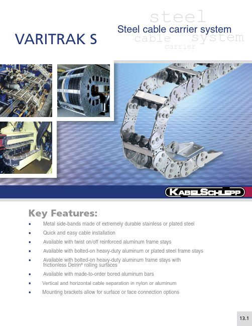
13.1• Metal side-bands made of extremely durable stainless or plated steel • Quick and easy cable installation• Available with twist on/off reinforced aluminum frame stays•Available with bolted-on heavy-duty aluminum or plated steel frame stays• Available with bolted-on heavy-duty aluminum frame stays with frictionless Delrin ® rolling surfaces • Available with made-to-order bored aluminum bars• Vertical and horizontal cable separation in nylon or aluminum •Mounting brackets allow for surface or face connection optionsVARITRAK SsteelcarriercablesystemSteel cable carrier system13V A R I T R A K S13.2Speci fi cations are subject to change without notice.KS-1106-GC-ASelf-Supporting Lengthssystems, KS Support Rollers or major credit cards acceptedA product group’s EVA score is a general indicator that allows a customer to quickly and easilyFor more information onextended travel systems, see pages 2.27-2.36Number of Systems Req.8x x +-+++-+++-xx Type & Position Brackets M A I /F A I # of Links Length 32 Links T ype Frame Stay RS2Dividers(#vert / #horz)5v/0hBend Radius 135Carrier TypeS0650.1Cavity Width 10.00”(B i )VARITRAK S steel• open style • customizable widthsNeed help?1-800-443-4216or 13VARITRAKS 13.3Specifi cations are subject to change without notice. KS-1106-GC-ASeries S 0650.1 Features one twist in/out aluminum bar on the outer radius and one bolted-on aluminum bar on the inner radius per frame stay.Usable Cavity Widths (B i)are available from2.00” (50.8 mm)through 12.00” (304.8 mm).Ten standard width sizes are available from stock. Custom widths are also available in any width increment required by the customer.RS1 Bar Systemdividers can be slid into position13V A R I T R A K S13.4Speci fi cations are subject to change without notice.KS-1106-GC-AFeatures bolted on aluminum bars on both the outer radius and the inner radius per frame able Cavity Widths (B i ) are available from 2.00” (51 mm) through 12.00” (304.8 mm).Ten standard width sizes are available from stock. Custom widths are also available in any width increment required by the customer.RS2Bar SystemMounting Bracket OptionsFor detailed drawings anddimensions of available options, please see pages: 13.32 - 13.33dividers can be slid into position0.12(3)=s TStandard RS2STYLE Vertical Divider=B i + 0.63 (16)=B i + 1.22 (31)h iRecommendedMAXIMUMWidthRecommendedMINIMUMWidthh G h G Note: For extended widths, multiple chain-band designs factory:1-800-443-42160.51(13)PN:44250S0650.1 - 2.00” - RS2 - (KR) - (# of links) - (brackets) - (dividers)S0650.1 - 12.00” - RS2 - (KR) - (# of links) - (brackets) - (dividers)bars on outside radiusB st = Cut bar length B k = Outer chain width B i = I nner chain cavity(usable) width h G = Outer chain link height h i = I nner chain cavity(usable) height S T = Vertical divider thicknessVARITRAK Ssteel • open style • customizable widthsNeed help? 1-800-443-4216 or 13V A R I T R A K S13.5Speci fi cations are subject to change without notice.KS-1106-GC-ASeriesS 0650.1Features bolted-on heavy-duty split and bored aluminum bars.Bar Widths (B st ) are available from 2.50” (63.5 mm) through 19.00” (482.6 mm) in any width increment required by the customer.LGBar System• B y simply unscrewing 1 bolt per split-bar at bothends of each bar and sliding out the unbolted split-bar, cables & hoses can be easily installed (laid inside, in each speci fi cally designed 1/2 round).• I deal when unique cables and hoses must beindividually separated.Why use LG system13V A R I T R A K S13.6Speci fi cations are subject to change without notice.KS-1106-GC-AWhen application travel exceeds major credit cards acceptedDDEDA product group’s EVA score is a general indicator For more information onextended travel systems,see pages 2.27-2.36Number of Systems Req.4x x +-+++-+++-xx Type & Position Brackets M A I /F A I # of Links Length 35 Links T ype Frame Stay RMR Dividers(#vert / #horz)9v/0hBend Radius 170Carrier TypeS0950Cavity Width 18.00”(B i )VARITRAK Ssteel • open style • customizable widthsNeed help? 1-800-443-4216 or 13V A R I T R A K S13.7Speci fi cations are subject to change without notice.KS-1106-GC-ASeriesS 0950Features one twist in/out aluminum bar on the outer radius and one bolted-on aluminum bar on the inner radius per frame stay.Usable Cavity Widths (B i ) are available from 3.00” (76.2 mm) through 11.00” (279.4 mm).Ten standard width sizes are available from stock. Custom widths are also available in any width increment required by the customer.RS1Bar Systemh G =B i + 0.94 (24)=B i + 1.69 (43)dividers can be slid into position0.16(4)=s TStandard RS1STYLE Vertical Dividerh iRecommendedMINIMUMWidth0.55(14)PN: 42160S0950 - 3.00” - RS1 - (KR) - (# of links) - (brackets) - (dividers)B st = Cut bar lengthB k = Outer chain width B i = I nner chain cavity(usable) width h G = Outer chain link height h i = I nner chain cavity(usable) height S T = Vertical divider thickness13V A R I T R A K S13.8Speci fi cations are subject to change without notice.KS-1106-GC-AMounting Bracket OptionsFor detailed drawings anddimensions of available options, please see pages: 13.32 - 13.33dividers can be slid into position0.16(4)=s TStandard RS2STYLE Vertical DividerB st B k =B i + 0.71 (18) =B i + 1.46 (37)h iRecommendedMAXIMUMWidthRecommendedMINIMUMWidthh G h G Note: For extended widths, multiple chain-band designs factory:1-800-443-42160.55(14)PN: 42160S0950 - 3.00” - RS2 - (KR) - (# of links) - (brackets) - (dividers)S0950 - 14.00” - RS2 - (KR) - (# of links) - (brackets) - (dividers)bars on outside radiusB st = Cut bar lengthB k = Outer chain width B i = I nner chain cavity(usable) width h G = Outer chain link height h i = I nner chain cavity(usable) height S T = Vertical divider thicknessFeatures bolted on aluminum bars on both the outer radius and the inner radius per frame able Cavity Widths (B i ) are available from 3.00” (76.2 mm) through 14.00” (355.6 mm).Ten standard width sizes are available from stock. Custom widths are also available in any width increment required by the customer.RS2Bar SystemVARITRAK Ssteel • open style • customizable widthsNeed help? 1-800-443-4216 or 13V A R I T R A K S13.9Speci fi cations are subject to change without notice.KS-1106-GC-ASeriesS 0950Features heavy-duty double bolted-on aluminum bar on the outer radius and on the inner radius per frame stay.Usable Cavity Widths (B i ) are available from 3.00” (76.2 mm) through 23.00” (584.2 mm) in any width increment required by the customer.RMSBar Systemdividers can be slid into position0.16(4)=s TStandard RMS STYLE Vertical DividerRecommendedMAXIMUMWidthRecommendedMINIMUMWidthNote:factory:1-800-443-4216h G st k =B i + 0.71 (18) =B i + 1.46 (37)h ih G 0.57(14.5)PN: 42130S0950 - 3.00” - RMS - (KR) - (# of links) - (brackets) - (dividers)S0950 - 23.00” - RMS - (KR) - (# of links) - (brackets) - (dividers)bars on outside radiusB st = Cut bar lengthB k = Outer chain width B i = I nner chain cavity(usable) width h G = Outer chain link height h i = I nner chain cavity(usable) height S T = Vertical divider thickness13V A R I T R A K S13.10Speci fi cations are subject to change without notice.KS-1106-GC-AFeatures heavy-duty double bolted-on aluminum bar with integrated roller system on the outer radius and on the inner radius per frame stay.Usable Cavity Widths (B i ) are available from 3.00” (76.2 mm) through 22.00” (558.8 mm) in any width increment required.RMRBar SystemVARITRAK Ssteel • open style • customizable widthsNeed help? 1-800-443-4216 or 13V A R I T R A K S13.11Speci fi cations are subject to change without notice.KS-1106-GC-ASeriesS 0950Features bolted-on heavy-duty split and bored aluminum barsBar Widths (B st ) are available from 3.00” (76.2 mm) through 23.00” (584.2 mm) in any width increment required by the customer.LGBar SystemMounting Bracket OptionsFor detailed drawings anddimensions of available options, please see pages: 13.32 - 13.3313V A R I T R A K S13.12Speci fi cations are subject to change without notice.KS-1106-GC-Amajor credit cards acceptedsystems, KS Support Rollers orDDEDA product group’s EVA score is a general indicator that allows a customer to quickly and easilyFor more information on extended travel systems,see pages 2.27-2.36Number of Systems Req.10x x +-+++-+++-xx Type & Position Brackets M F/F F # of Links Length 27 Links T ype Frame Stay RS1Dividers(#vert / #horz)11v/2hBend Radius 260Carrier Type S1250Cavity Width 22.00”(B i )VARITRAK Ssteel • open style • customizable widthsNeed help? 1-800-443-4216 or 13V A R I T R A K S13.13Speci fi cations are subject to change without notice.KS-1106-GC-ASeries1250 Sh G =B i + 0.94 (24)=B i + 1.89 (48)h iRecommendedMINIMUMWidthdividers can be slid into position0.20(5)=s TStandard RS1STYLE Vertical Divider0.59(15)PN: 42900dividers can be slid into positionS1250 - 4.00” - RS1 - (KR) - (# of links) - (brackets) - (dividers)B st = Cut bar lengthB k = Outer chain width B i = I nner chain cavity(usable) width h G = Outer chain link height h i = I nner chain cavity(usable) height S T = Vertical divider thicknessFeatures one twist in/out aluminum bar on the outer radius and one bolted-on aluminum bar on the inner radius per frame stay.Usable Cavity Widths (B i ) are available from 4.00” (101.6 mm) through 14.00” (355.6 mm).Ten standard width sizes are available from stock. Custom widths are also available in any width increment required by the customer.RS1Bar System13V A R I T R A K S13.14Speci fi cations are subject to change without notice.KS-1106-GC-Adividers can be slid into position0.20(5)=s TStandard RS2STYLE Vertical Divider=B i + 0.79 (20)=B i + 1.73 (44)h iRecommendedMAXIMUMWidthRecommendedMINIMUMWidthh G h G Note: For extended widths, multiple chain-band designs factory:1-800-443-42160.59(15)PN: 42900S1250 - 4.00” - RS2 - (KR) - (# of links) - (brackets) - (dividers)S1250 - 18.00” - RS2 - (KR) - (# of links) - (brackets) - (dividers)bars on outside radiusB st = Cut bar lengthB k = Outer chain width B i = I nner chain cavity(usable) width h G = Outer chain link height h i = I nner chain cavity(usable) height S T = Vertical divider thicknessFeatures bolted on aluminum bars on both the outer radius and the inner radius per frame able Cavity Widths (B i ) are available from 4.00” (101.6 mm) through 18.00” (457.2 mm).Ten standard width sizes are available from stock. Custom widths are also available in any width increment required by the customer.RS2Bar SystemVARITRAK Ssteel • open style • customizable widthsNeed help? 1-800-443-4216 or 13V A R I T R A K S13.15Speci fi cations are subject to change without notice.KS-1106-GC-ASeries1250 SFeatures heavy-duty double bolted-on aluminum bar on the outer radius and on the inner radius per frame stay.Usable Cavity Widths (B i ) are available from 4.00” (101.6 mm) through 30.00” (762 mm) in any width increment required by the customer.RMSBar System13V A R I T R A K S13.16Speci fi cations are subject to change without notice.KS-1106-GC-AFeatures heavy-duty double bolted-on aluminum bar with integrated roller system on the outer radius and on the inner radius per frame stay.Usable Cavity Widths (B i ) are available from 4.00” (101.6 mm) through 30.00” (762 mm) in any width increment required.RMRBar SystemVARITRAK Ssteel • open style • customizable widthsNeed help? 1-800-443-4216 or 13V A R I T R A K S13.17Speci fi cations are subject to change without notice.KS-1106-GC-ASeriesFeatures bolted-on heavy-duty split and bored aluminum bars.Bar Widths (B st ) are available from 4.00” (101.6 mm) through 30.50” (774.7 mm) in any width increment required by the customer.LGBar SystemMounting Bracket OptionsFor detailed drawings anddimensions of available options, please see pages: 13.32 - 13.3313V A R I T R A K S13.18Speci fi cations are subject to change without notice.KS-1106-GC-AFeatures medium-duty double bolted-on aluminum bar compatible with integrated easy snap-in vertical and horizontal divider system.Usable Cavity Widths (B i ) are available from 4.00” (101.6 mm) through 21.00” (533.4 mm) in any width increment required.RVBar SystemVARITRAK S steel• open style • customizable widthsNeed help?1-800-443-4216or 13VARITRAKS 13.19Specifi cations are subject to change without notice. KS-1106-GC-A SeriesThe carrier cavity width can be easily divided vertically - so cables or hoses can be safely separated side by side - next to one another. If small cables are to be stacked or cables with varying diameters are being used, the option to add horizontal shelving to properly accommodate these can be easily done by simply adding a shelf at the height desired. The various vertical levels that are available for the horizontal shelves are defined in this catalog section. The applicable kit components part numbers (dividers and shelves) are clearly identified.Varitrak 1250 RV Horizontal Shelving- optional widths(5.8)Horizontal shelves can be easily pressed and locked into placebetween the specially designed RV vertical dividers. This makeshorizontal and vertical partitioning of the carrier’s cavity easyto install and highly fl exible to meet your application’s uniqueneeds.13V A R I T R A K S13.20Speci fi cations are subject to change without notice.KS-1106-GC-Amajor credit cards acceptedDDEDA product group’s EVA score is a general indicator systems, KS Support Rollers or Self-Supporting Lengthskg m lbs ft 6040.3For more information on Number of Systems Req.8x x +-+++-+++-xx Type & Position Brackets M A I /F A I # of Links Length 85 Links T ype Frame Stay RMS Dividers(#vert / #horz)9v/1hBend Radius 435Carrier TypeS1800Cavity Width 18.00”(B i )VARITRAK Ssteel • open style • customizable widths13V A R I T R A K SSeries1800 SFeatures heavy-duty double bolted-on aluminum bar on the outer radius and on the inner radius per frame stay.Usable Cavity Widths (B i ) are available from 6.00” (152.4 mm) through 37.00” (939.8 mm) in any width increment required by the customer.RMSBar System13V A R I T R A K SFeatures heavy-duty double bolted-on aluminum bar with integrated roller system on the outer radius and on the inner radius per frame able Cavity Widths (B i ) are available from 6.00” (152.4 mm) through 38.00” (965.2 mm) in any width increment required.RMRBar SystemVARITRAK Ssteel • open style • customizable widths13V A R I T R A K SSeries1800 SFeatures bolted-on heavy-duty split and bored aluminum barsBar Widths (B st ) are available from 6.00” (152.4 mm) through 39.00” (990.6 mm) in any width increment required by the customer.LGBar SystemMounting Bracket OptionsFor detailed drawings anddimensions of available options, please see pages: 13.32 - 13.33B st = Cut bar length B k = Outer chain width h G = Outer chain link heightD max = Maximum hole diameter C min = M inimum distancebetween holesa o min = M inimum hole offset from end13V A R I T R A K Ssystems, KS Support Rollersmajor credit cards acceptedDDEDA product group’s EVA score is a general indicator that allows a customer to quickly and easilyFor more information on extended travel systems,see pages 2.27-2.36Number of Systems Req.10x x +-+++-+++-xx Type & Position Brackets M A/F I # of Links Length 63 Links T ype Frame Stay RMS Dividers(#vert / #horz)15v/3hBend Radius 760Carrier TypeS2500Cavity Width 30.72”(B i )VARITRAK Ssteel • open style • customizable widths13V A R I T R A K SSeries2500 SFeatures heavy-duty double bolted-on aluminum bar on the outer radius and on the in-ner radius per frame stay.Usable Cavity Widths (B i ) are available from 7.00” (177.8 mm) through 56.00” (1422.4 mm) in any width increment required by the customer.RMSBar Systemdividers can be slid into position0.31(8)=s TStandard RMS STYLE Vertical DividerRecommendedMAXIMUM WidthRecommendedMINIMUM WidthNote:factory:1-800-443-4216h G h G = B st B k B i =7.00(177.8)8.30(210.8)9.52(241.8)8.66(220)=B i + 1.30 (33) =B i + 2.52 (64)7.20(183)=h iB st =B k =S2500 - 7.00” - RMS - (KR) - (# of links) - (brackets) - (dividers)S2500 - 56.00” - RMS - (KR) - (# of links) - (brackets) - (dividers)B st = Cut bar length B k = Outer chain widthB i = I nner chain cavity(usable) width h G = Outer chain link height h i = I nner chain cavity(usable) height S T = Vertical divider thickness13V A R I T R A K SSeries2500 SFeatures bolted-on heavy-duty split and bored aluminum barsBar Widths (B st ) are available from 8.50” (215.9 mm) through 46.00” (1168.4 mm) in any width increment required by the customer.LGBar SystemMounting Bracket OptionsFor detailed drawings anddimensions of available options, please see pages: 13.34 - 13.35B st = Cut bar lengthB k = Outer chain width h G = Outer chain link heightD max = Maximum hole diameter C min = M inimum distancebetween holesa o min = M inimum hole offset from endVARITRAK Ssteel • open style • customizable widths13V A R I T R A K SName: Date: Dept.: Phone:Fax:Company: Machine Type/Name:Address:13V A R I T R A K Smajor credit cards acceptedsystems, KS Support Rollers can be used to extend travel.Self-Supporting Lengths150101S 3200kgm lbs ftUnsupported LengthDDEDA product group’s EVA score is a general indicator For more information on extended travel systems, see pages 2.27-2.36Number of Systems Req.10x x +-+++-+++-xx Type & Position Brackets M I/F I # of Links Length 42 Links T ype Frame Stay LG # ofHoles33Bend Radius 1275Carrier TypeS3200Bar Width42.50”(B st )VARITRAK Ssteel • open style • customizable widths13V A R I T R A K SSeries3200 SFeatures bolted-on heavy-duty split and bored aluminum bars.Bar Widths (B st ) are available from 10.50” (266.7 mm) through 57.00” (1447.8 mm) in any width increment required by the customer.LGBar SystemMounting Bracket OptionsFor detailed drawings anddimensions of available options, please see pages: 13.34 - 13.35RecommendedMAXIMUMWidthNote:factory:1-800-443-4216h G S3200 - 57.00” - LG - (KR) - (# of links) - (brackets) - (holes)B st = Cut bar length B k = Outer chain width h G = Outer chain link heightD max = Maximum hole diameter C min = M inimum distancebetween holesa o min = M inimum hole offset from end13V A R I T R A K SVaritrak Series S/SX 5000, 6000, 7000 and LargerDo you have an application that is super-sized? KabelSchlepp has a long and successful history of supplying Super-Duty Cable and Hose Carrier systems in a wide range of industries and applications. Using standard components and proven technologies, KabelSchlepp Super-Duty Steel Cable and Hose Carrier Systems can be custom manufactured to meet your individual application requirements. Call your KabelSchlepp factory representative at 1-800-443-4216 for complete information and design assistance!• Rugged Super-Duty systems that can be scaled to meet EXTREME size and load requirements.• A vailable in high-grade galvanized (Type S) or stainless steel (Type SX) with a variety of environment andapplication speci fi c coatings.• U tilizing standard components and cutting edge manufacturing technology, systems can be designed, manufactured and installed in record time.• Select from a wide variety of frame stay and partitioning options custom con fi gured to your unique needs.• W ork with a team of dependable and experienced engineers who understand the unique requirements ofsuper-duty applications to ensure project success.SUPER-DUTY Steel Cable and Hose Carrier SystemsVARITRAK Ssteel • open style • customizable widthsNeed help? 1-800-443-4216 or 13V A R I T R A K S13.31Speci fi cations are subject to change without notice.KS-1106-GC-ADimensional DataSeries(t ) Link Pitchh i maxh GB k minB k maxS/SX 5000t = 7.87 (200) 5.91 (150)7.87 (200)9.84 (250)47.24 (1200)S/SX 6000t = 12.60 (320)9.45 (240)11.81 (300)11.81 (300)59.06 (1500)S/SX 7000t = 17.72 (450)14.57 (370)17.72 (450)13.78 (350)70.87 (1800)Larger systems and special designs are possible. Call your KabelSchlepp factory representative at1-800-443-4216 for complete information and design assistance!General Data for Super-Duty Steel SystemsAvailable Bend Radii (KR)SeriesBend Radii (KR)S/SX 500019.69 (500)23.62 (600)31.50 (800)39.37 (1000))47.24 (1200)S/SX 600027.56 (700)35.43 (900)43.31 (1100)51.18 (1300)59.06 (1500)S/SX 700043.31 (1100)49.21 (1250)59.06 (1500)70.87 (1800)94.49 (2400)Application speci fi c bend radii are possible upon request.Dimensions in inches (mm)Dimensions in inches (mm)Self-Supporting LengthK RWhen a Super-Duty carrier system’s self-supporting length is exceeded, KabelSchlepp can incorporate a KS Rolling Carriage System to provide adequate support over the entire distance of travel. See Extended Travel Systems section of the Technical Handbook pages 2.27-2.36 for more information.13V A R I T R A K S13.32Speci fi cations are subject to change without notice.KS-1106-GC-AStandard Mount - Fixed End BracketsStandard Mount - Moving End BracketsSize a b c d e f g h i j k S0650B k + 0.98 (25)B k – 1.45 (37)0.68 (17)0.51 (13) 1.18 (30)0.12 (3)0.20 (5)0.59 (15) 1.77 (45) 3.74 (95)0.25 (6.4)S0950B k + 1.93 (49)B k – 2.48 (63) 1.18 (30)0.98 (25) 2.16 (55)0.15 (4)0.39 (10)0.79 (20) 2.55 (65) 4.91 (125)0.33 (8.4)S1250B k + 1.81 (46)B k – 2.52 (64) 1.18 (30)0.98 (25) 2.16 (55)0.19 (5)0.39 (10)0.98 (25) 3.14 (80) 6.09 (155)0.41 (10.5)S1800B k + 2.08 (53)B k – 3.03 (77)1.38 (35)0.98 (25)2.36 (60)0.19 (5)0.39 (10)1.18 (30)4.52 (115)8.25 (210)0.51 (13)Size lm n o p q r s t u v S0650B k + 0.75 (19)B k – 1.69 (43)0.68 (17)0.51 (13) 1.18 (30)0.12 (3)0.20 (5)0.59 (15) 1.77 (45) 3.74 (95)0.25 (6.4)S0950B k + 1.61 (41)B k – 2.79 (71) 1.18 (30)0.98 (25) 2.16 (55)0.16 (4)0.39 (10)0.79 (20) 2.55 (65) 4.91 (125)0.33 (8.4)S1250B k + 1.41 (36)B k – 2.91 (74) 1.18 (30)0.98 (25) 2.16 (55)0.20 (5)0.39 (10)0.98 (25) 3.14 (80) 6.09 (155)0.41 (10.5)S1800B k + 1.61 (41)B k – 3.46 (88)1.38 (35)0.98 (25)2.36 (60)0.20 (5)0.39 (10)1.18 (30)4.52 (115)8.25 (210)0.51 (13)M K M HM A (Standard)M IF IF A (Standard)F HF KPlease specify the desired bracket variant and position when orderingExample: F A I /M A I (Standard) or F A A /M I AThe bracket positions at the Fixed End and Moving End can be changed later if required.Bracket EndM - Moving End F - Fixed EndBracket PositionA -c onnecting surface on outside radius (standard)I - c onnecting surface oninside radius H - c onnecting surface turned 90°to the outside radius K - c onnecting surface turned 90°to the inside radius F - face/flange mount (see opposite page)Varitrak S Standard BracketPosition OptionsAI (Standard)I (Standard)ABracket feet on the standard brackets can be positioned facing inward (I ) which is the standard position or facing outward (A ).Dimensions in inches (mm)Dimensions in inches (mm)VARITRAK Ssteel • open style • customizable widthsNeed help? 1-800-443-4216 or 13V A R I T R A K S13.33Speci fi cations are subject to change without notice.KS-1106-GC-AFace Mount - Fixed End BracketsFace Mount - Moving End BracketsSize ab c def ghij kl S0950B i + 4.84 (122.9)B i + 3.09 (78.5)-0.88 (22.4) 1.75 (44.5)0.16 (4)0.75 (19.1)0.50 (12.7) 3.00 (88.9)3.50 (88.9)0.41 (10.4)4.00 (101.6)S1250B i +5.27 (133.9)B i + 3.52 (89.4)-0.88 (22.4) 1.75 (44.5)0.18 (4.6)0.75 (19.1)0.50 (12.7) 3.00 (88.9)3.50 (88.9)0.41 (10.5)4.00 (101.6)S1800B i + 7.39 (187.7)B i + 4.78 (124.4) 2.00 (50.8) 1.31 (33.3) 2.63 (66.8)0.20 (5.1) 1.00 (25.4)1.26 (32)3.00 (88.9)4.50 (114.3)0.56 (14.2)5.51 (140)Size mn o pqr stuv wx S0950B i + 4.52 (114.8)B i + 2.77 (70.4)-0.88 (22.4) 1.75 (44.5)0.16 (4)0.75 (19.1)0.50 (12.7) 3.00 (88.9)3.50 (88.9)0.41 (10.4)4.00 (101.6)S1250B i + 4.88 (124)B i + 3.13 (79.5)-0.88 (22.4) 1.75 (44.5)0.18 (4.6)0.75 (19.1)0.50 (12.7) 3.00 (88.9)3.50 (88.9)0.41 (10.5)4.00 (101.6)S1800B i + 6.92 (175.8)B i + 4.29 (109)2.00 (50.8) 1.31 (33.3) 2.63 (66.8)0.20 (5.1) 1.00 (25.4) 1.26 (32)3.00 (88.9)4.50 (114.3)0.56 (14.2)5.51 (140)Bracket EndM - Moving End F - Fixed EndBracket DesignationF - Face Mount Bracket (standard position)Varitrak SFace/Flange Mount BracketWhen specifying Varitrak S Face Mount Brackets, use the letter F for the Bracket Position designation of the assembly part number description.Example: F F/M FDimensions in inches (mm)Dimensions in inches (mm)13.34Speci fi cations are subject to change without notice.KS-1106-GC-AVARITRAK S Series Standard Mounting Brackets For S/SX 2500 & S/SX 3200KabelSchlepp mounting brackets for Varitrak S 2500 and 3200 series carriers are available in both standard steel (S) or high-grade stainless steel (SX).VARITRAK Ssteel • open style • customizable widthsNeed help? 1-800-443-4216 or 13V A R I T R A K S13.35Speci fi cations are subject to change without notice.KS-1106-GC-AVARITRAK S/SX 2500 & S/SX 3200 Bracket Position OptionsA (Standard)IBracket EndM - Moving End F - Fixed EndBracket PositionA -c onnecting surface on outside radius (standard)I - c onnecting surface oninside radiusPlease specify the desired bracket variant and position when ordering .Example: F A/M A (Standard) or F A/M IThe bracket positions at the Fixed End and Moving End can be changed later if required.VARITRAK S Series Mounting Brackets For S/SX 5000, 6000, & 7000KabelSchlepp mounting brackets for Varitrak 5000, 6000 and 7000 S/SX series carriers are available in both standard steel (S) or high-grade stainless steel (SX). Custom designed brackets per system requirements are also available. Call your KabelSchlepp factory representative at 1-800-443-4216 for complete information and design assistance!。
电缆选型手册及常用公式
电缆的选型与配线选择电线平方数和电流一般铜线安全电流最大为:平方毫米铜电源线的安全载流量--。
平方毫米铜电源线的安全载流量--。
平方毫米铜电源线的安全载流量--。
平方毫米铜电源线的安全载流量--。
平方毫米铜电源线的安全载流量--。
平方毫米铜电源线的安全载流量--。
如果是铝线截面积要取铜线的倍。
如果铜线电流小于,按每平方毫米来取肯定安全。
如果铜线电流大于,按每平方毫米来取。
导线的截面积所能正常通过的电流可根据其所需要导通的电流总数进行选择,一般可按照如下顺口溜进行确定:十下五,百上二, 二五三五四三倍,七零九五两倍半,铜线升级算.就是平方以下的铝线,平方毫米数乘以就可以了,要是铜线呢,就升一个档, 比如平方的铜线,就按铝线平方计算.一百以上的都是截面积乘以, 二十五平方以下的乘以, 三十五平方以上的乘以, 和平方都乘以,这么几句口诀应该很好记吧,说明:只能作为估算,不是很准确。
另外如果按室内记住电线平方毫米以下的铜线,每平方电流不超过就是安全的,从这个角度讲,你可以选择平方的铜线或平方的铝线。
米内,导线电流密度平方毫米比较合适,米,平方毫米米,平方毫米,米以上要小于平方毫米。
从这个角度,如果不是很远的情况下,你可以选择平方铜线或者平方铝线。
如果真是距离米供电(不说是不是高楼),一定采用平方的铜线。
导线的阻抗与其长度成正比,与其线径成反比。
请在使用电源时,特别注意输入与输出导线的线材与线径问题。
以防止电流过大使导线过热而造成事故。
导线线径一般按如下公式计算:铜线:*`铝线:*`式中:——导线中通过的最大电流()——导线的长度()`——充许的电压降()——导线的截面积()说明:、`电压降可由整个系统中所用的设备范围内,分给系统供电用的电源电压额定值综合起来考虑选用。
、计算出来的截面积往上靠. 绝缘导线载流量估算铝芯绝缘导线载流量与截面的倍数关系导线截面( )载流是截面倍数载流量()估算口诀:二点五下乘以九,往上减一顺号走。
igus拖链标准长行程滑行使用-设计选型介
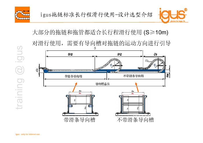
t r a i n i n g @ i g u s 大部分的拖链和拖管都适合长行程滑行使用(S ≥10m)对滑行使用,需要有导向槽对拖链的运动方向进行引导带滑条导向槽不带滑条导向槽t r a i n i n g @ i g u s 长行程拖链设计选型步骤:1.收集设计参数,包括:行程,速度,加速度,使用频率,工况,内部管线的直径、重量及最小弯曲半径,系统安装空间2.根据内部管线确定拖链弯曲半径(弯曲半径越小,拖链承载能力越大)3.根据拖链内部管线重量确定拖链型号(参考设计选型表)4.校核拖链的最大驱动力F PPFt r a i n i n g @ i g u s 何谓驱动力?F friction.F acc.F a 为拖链运动时最大加速度g =10m/s²µ= 摩擦系数F acc (m x a) + F 摩擦(m x µx g)= F PPFm 为拖链的质量(含在拖链内的管线重量),单位为kgt r a i n i n g @ i g u s注:设计选型表的数据都是基于以下使用条件时¾拖链根据图纸要求,采用降低高度安装¾V ≤1m/s¾环境温度+5°C 到+ 50°C¾环境湿度不超过70 %¾igus 标准材料的拖链(黑色)对超过以上条件的使用环境,拖链的型号需要进一步校核,请联系igus 的专业工程师t r a i n i n g @ i g u s 是否需要使用支撑板?¾当实际驱动力超过许用驱动力50%的时候,移动端需使用支撑板(推荐支撑板角度10~15°,长度约为3节拖链)不带支撑板带支撑板PPFP P FPPF PPF 此处受力最大t r a i n i n g @ i g u s Questions?Answers?Comments?Thank you for your attention!。
拖链电缆SPC-LiYCP

拖链电缆SPC-LiYCPSPCDATA-CHAIN-PUR-LiYCP高柔性聚氨酯拖链数据电缆PUR 高柔性数据传输拖链电缆电缆名称:SPCDATA-CHAIN-PUR-LiYCP高柔性聚氨酯数据拖链电缆PUR 高柔性数据传输拖链电缆LiYCP柔性数据拖链电缆柔性拖链电缆LiYCP 柔性数据传输拖链电缆LiYCP德标数据拖链电缆LiYCP数据拖链电缆LiYCP欧标柔性数据拖链电缆LiYP欧标数据拖链电缆LiYCP信号电缆LiYCP信号传输电缆LiYCP数据传输电缆数据电缆数据传输电缆PVC 数据电缆PVC数据传输电缆PVC柔性数据传输电缆柔性数据传输电缆信号电缆信号传输电缆RS485串口线高柔性聚氨酯电缆RS485信号线RS485信号传输电缆拖链电缆高柔性拖链电缆聚氨酯拖链电缆聚氨酯数据拖链电缆聚氨酯护套数据拖链电缆电缆应用:动力拖链或移动机械部件计算机系统、电子设备、电气成套、仪器仪表、办公设备、自动化系统、工业电子系统、安防系统等数据和信号传输需要出色的机械性能和耐化学性能的工业环境需要抗电磁干扰的环境适合干燥或潮湿的室内移动安装在指定使用温度范围内,才可用于户外电缆结构:导体:多股精绞细丝导体,符合VDE 0295及IEC 60288第6类导体绝缘:特殊PVC混合料芯线:芯线绞合成缆,芯线颜色符合DIN 47100 色标,无重复颜色屏蔽:镀锡铜线编织,编织密度≥80%护套:特殊PUR混合料护套颜色:黑色或灰色,可根据客户需要定选用各种颜色电缆特性:电缆的长期工作温度应不超过70℃低粘性表面、耐磨、抗撕裂、耐油、抗紫外线能承受中等的机械应力具有较强的抗电磁干扰能力适用于拖链系统中频繁连续弯曲600万次电缆技术参数:< 0.25mm2时:工作电压350 V 测试电缆1200V≥ 0.25 mm2时:工作电压500 V 测试电缆1500V导体电阻20℃:根据VDE 0295及IEC 60228第6类绝缘电阻:≥ 20 MΩ/km (20℃)互电容:C/C:最大120 nF/kmC/S:大约160 nF / km电感:约0.65 mH/km最小弯曲半径:固定安装5 X D(电缆外径)移动安装:当行程<10米时,弯曲半径为10 X D(电缆外径)当行程≥10米时,弯曲半径为12 X D(电缆外径)移动特性:敷设行程:80米,加速度50米/秒2,移动速度≤5米/秒弯曲寿命:30次/分钟,>600万次工作温度:固定安装- 40 ~ +80℃移动安装- 30 ~ +70℃外护套抗油性:符合IEC60811-2-1电缆名称电缆型号额定电压对数导体结构标称截面mm2高柔性聚氨酯数据拖SPCDATA-CHAIN-LiYCP 350V 1 ~ 100 多股精绞细丝导体0.12 ~ 0.22 链电缆屏蔽型高柔性聚氨酯数据拖SPCDATA-CHAIN-LiYCP 500V 1 ~ 100 多股精绞细丝导体0.25~ 1.5 链电缆屏蔽型注:以上规格为常用型,可根据用户要求定制特殊规格。
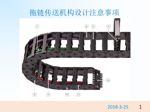
拖链设计
弯曲 半径 不足
拖链运动容易引发的问题: 1、拖链里的线容易磨损,容易磨破皮,导致引发信号短路故障。信号接触不良。 有可能只是运动到某个位置,cable被折到,引发故障。需要根据报警信息和时 间情况来进行排查。这种问题也是比较难对付的问题。 cable不是运动型专用柔性cable时,线容易有内伤。电源供应不稳定故障,比较 有名的是:DIVERTER HDA DROP,由于ATS DC24V电源线内伤,导致ZONE CARD有 重启的现象,重启后与重启前的I/O输出信号异常,导致PALLET DROP。 2、拖链里的气管也容易磨损。皮管磨破,导致漏气,严重的漏气可以听出来。 轻微漏气很难被发现。处理的时候需要及时了解管路的来龙去脉,及时果断地 处理。看气缸运动的速度和动作;真空的大小来判断。 对策: 1、要保证拖链里的CABLE 气管排列整齐,在运动的时候不能有明显打折的情况。 2、也不能绷得太直。绷得太直了CABLE 容易导致内伤。 3、拖链里不能有气管接头。如果气管磨损了,整条更换。因为接头在保护链运 动的时候很容易松动,接头太硬对cable的伤害也很大。
1、你们上面的R是代表什么,这个怎么选? 答:R是代表拖链的弯曲半径,它最主要取决于安装空间 ,如您现选30*100桥式拖链, 安装空间是300,那么R=(300-45)/2=127.5,就可以选我们这里跟这个差不多的半径: 125,【R=(安装空间—外高)/2】 2、是不是弯曲半径越大越好啊? 答:不是的,看一款拖链的质量好坏最主要的是看拖链的结构与材质,弯曲半径只与 安装空间有关 3、拖链的使用长度怎么算啊? 答:使用长度=R+0.5R+行程/2,如您现选300*100R125拖链,行程为200,那需要买: 125+0.5*125+200/2=287.5mm长的拖链 4、拖链接头是哪样的? 答:加强型拖链接头均为方形接头,一条拖链配接头一付。 5.如果穿的线缆比较多比较乱怎么办 答:如果放置的线缆很多的话可以再拖链内部放置隔离片使线缆分开。
拖链电缆
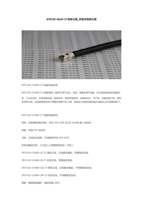
SPCFLEX-CHAIN-CY拖链电缆_屏蔽型拖链电缆SPCFLEX-CHAIN-CY拖链电缆应用:SPCFLEX-CHAIN-CY拖链电缆一般用于用于动力、控制、测量及调节电路、动力拖链或移动机械部件,如:工业自动化、机电成套设备、数控机床、物流传输系统、机械自动化、生产线、设备安装工程、控制系统等方面。
此拖链电缆适用于需要抗电磁干扰,干燥,潮湿及水油混合物的室内或室外,且不能直埋地下。
SPCFLEX-CHAIN-CY拖链电缆结构:导体:多股精绞细丝导体,符合VDE 0295及IEC 60288第6类导体绝缘:特殊PVC混合料芯线:芯线绞合成缆,芯线颜色符合VDE 0293彩色或编码芯线,3芯及以上带黄绿双色线(可选)SPCFLEX-CHAIN-JZ-CY黑色芯线、白色数字编码、带黄绿双色线SPCFLEX-CHAIN-JB-CY彩色芯线、带黄绿双色线SPCFLEX-CHAIN-OZ-CY黑色芯线、白色数字编码、不带黄绿双色线SPCFLEX-CHAIN-OB-CY彩色芯线、不带黄绿双色线屏蔽:镀锡铜线编织,编织密度≥80%护套:特殊改性PVC混合料护套颜色:黑色、灰色或橙色,可根据客户需要定选用各种颜色SPCFLEX-CHAIN-CY拖链电缆特性:SPCFLEX-CHAIN-CY拖链电缆电缆的长期工作温度应不超过70℃,其具有防水、耐油、耐寒、耐磨、抗紫外线,能承受中等的机械应力等优点,且具有较强的抗电磁干扰能力,用于拖链系统中频繁连续弯曲能达300万次。
其阻燃特性符合VDE 0472-804部分B类测试标准和IEC 60332-1-2SPCFLEX-CHAIN-CY拖链电缆技术参数:工作电压:300/500V 450/750V 600/1000V测试电缆:2000V 2500V 3500V导体电阻20℃:根据VDE 0295及IEC 60228第6类绝缘电阻:≥20 MΩ/km (20℃)最小弯曲半径:固定安装6 X D(电缆外径)移动安装:当行程<10米时,弯曲半径为10 X D(电缆外径)当行程≥10米时,弯曲半径为12 X D(电缆外径)移动特性:敷设行程:50米,加速度20米/秒2,移动速度≤2米/秒弯曲寿命:30次/分钟,>300万次工作温度:固定安装-30 ~ +70℃移动安装- 5 ~ +70℃护套抗油性:符合IEC60811-2-1。
高明电缆拖链技术参数

高明电缆拖链技术参数高明电缆拖链技术参数作为机床的重要附件之一,电缆拖链是连接设备与机器人等设备的重要元件,而高明电缆拖链作为电缆拖链的品牌之一,其技术参数必须得到充分的了解和掌握。
下面我们将详细介绍高明电缆拖链的技术参数。
1.外观尺寸高明电缆拖链的外观尺寸从10mm到300mm不等,长度也不固定,可以根据不同的需求进行调整。
根据机器设备的规格及安装位置不同,需要有不同尺寸可供选择,以达到最佳的适配效果。
2.速度范围高明电缆拖链的速度范围在5米/秒到20米/秒之间,可以适应不同的机器设备速度。
对于高速运转的机器设备,可以选择速度较快的电缆拖链来确保其稳定性和使用寿命。
3.弯曲半径高明电缆拖链的弯曲半径也是关键技术指标之一。
不同尺寸的电缆拖链具有不同的最小弯曲半径,最小弯曲半径越小,电缆拖链的可弯曲性就越好。
在机器设备不断进行移动的过程中,必须考虑到其运动的全方位性能,对弯曲半径的掌握要尽可能做到精准。
4.负载能力负载能力是电缆拖链的重要参数之一,高明电缆拖链最高的负载能力为30kg/m左右,适用于不同的负荷需求。
在使用过程中,需要在可接受的范围内控制载荷,以确保电缆拖链的使用寿命和稳定性。
5.防护等级高明电缆拖链的防护等级可达到IP40-IP65级别,可以防护泥沙、水、尘埃等外部破坏因素的进入,保证电缆拖链内部电缆线的安全和可靠。
6.耐腐蚀性高明电缆拖链的材质采用高质量的耐腐蚀性化学材料,可以承受不同气氛和酸碱等腐蚀性环境的影响。
7.耐磨性能高明电缆拖链的耐磨性能也十分突出,在多次使用和折叠的过程中,其内部电缆线可以得到很好的保护,使其使用寿命更长。
8.温度范围高明电缆拖链的温度范围为-40度到120度之间,可以适应不同温度环境下的机器设备使用,使设备性能稳定可靠。
综上所述,高明电缆拖链的技术参数十分完备,可以根据不同机器设备的需要进行合理选择,从而达到最佳的使用效果。
在使用过程中,需要按照生产厂家的使用说明来进行正确的安装和操作,以确保电缆拖链的安全、可靠和稳定。
电缆选型手册及常用公式
电缆的选型与配线选择电线平方数和电流一般铜线安全电流最大为:2.5 平方毫米铜电源线的安全载流量--28A。
4 平方毫米铜电源线的安全载流量--35A 。
6 平方毫米铜电源线的安全载流量--48A 。
10 平方毫米铜电源线的安全载流量--65A。
16 平方毫米铜电源线的安全载流量--91A 。
25 平方毫米铜电源线的安全载流量--120A。
如果是铝线截面积要取铜线的1.5-2 倍。
如果铜线电流小于28A,按每平方毫米10A 来取肯定安全。
如果铜线电流大于120A,按每平方毫米5A 来取。
导线的截面积所能正常通过的电流可根据其所需要导通的电流总数进行选择,一般可按照如下顺口溜进行确定:十下五,百上二, 二五三五四三倍,七零九五两倍半,铜线升级算.就是10 平方以下的铝线,平方毫米数乘以 5 就可以了,要是铜线呢,就升一个档, 比如 2.5 平方的铜线,就按铝线 4 平方计算.一百以上的都是截面积乘以2, 二十五平方以下的乘以4, 三十五平方以上的乘以3, 70 和95 平方都乘以2.5,这么几句口诀应该很好记吧,说明:只能作为估算,不是很准确。
另外如果按室内记住电线6 平方毫米以下的铜线,每平方电流不超过10A 就是安全的,从这个角度讲,你可以选择1.5 平方的铜线或2.5 平方的铝线。
10 米内,导线电流密度6A/平方毫米比较合适,10-50 米,3A/平方毫米,50-200 米,2A/平方毫米,500 米以上要小于1A/平方毫米。
从这个角度,如果不是很远的情况下,你可以选择 4 平方铜线或者 6 平方铝线。
如果真是距离150 米供电(不说是不是高楼),一定采用 4 平方的铜线。
导线的阻抗与其长度成正比,与其线径成反比。
请在使用电源时,特别注意输入与输出导线的线材与线径问题。
以防止电流过大使导线过热而造成事故。
导线线径一般按如下公式计算:铜线:S= IL / 54.4*U`铝线:S= IL / 34*U`式中:I——导线中通过的最大电流(A)L——导线的长度(M)U`——充许的电压降(V)S——导线的截面积(MM2)说明:1、U`电压降可由整个系统中所用的设备范围内,分给系统供电用的电源电压额定值综合起来考虑选用。
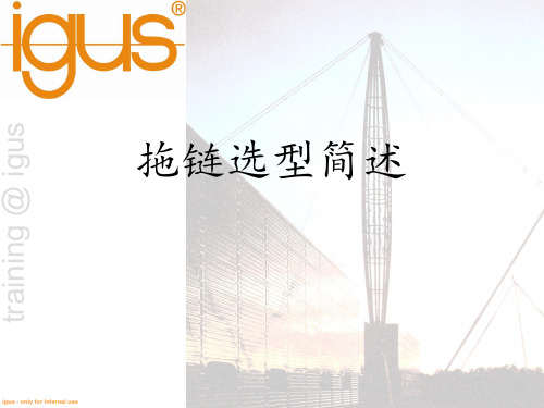
igus拖链选型简述 ppt课件
11
拖链选型简述
training @ igus
igus - only for internal use
12
架空-短行程应用
拖链选型简述
training @ igus
igus - only for internal use
13
滑动-长行程
拖链选型简述
training @ igus
igus - only for internal use
拖链选型简述
选型指南 5.
6.
igus - only for internal use
9
拖链选型简述
选型指南 7.
8.
training @ igus
igus - only for internal use
10
拖链选型简述 拖链长度计算
training @ igus
igus - only for internal use
14
滑动-长行程
拖链选型简述
training @ igus
长行程滑行拖链设计计算复杂,选型精确(对应加速度,速度),且相关的配件(导向槽,电缆 啦,隔片,浮动头,耐磨滑条等)较多。涉及到长行程拖链设计需求的请一定咨询igus!
igus - only for internal use
15
拖链选型简述
igus - only for internal use
26
拖链选型简述
THANK YOU VERY MUCH!
training @ igus
igus - only for internal use
27
training @ igus
igus - only for internal use
拖链选型、安装及注意事项
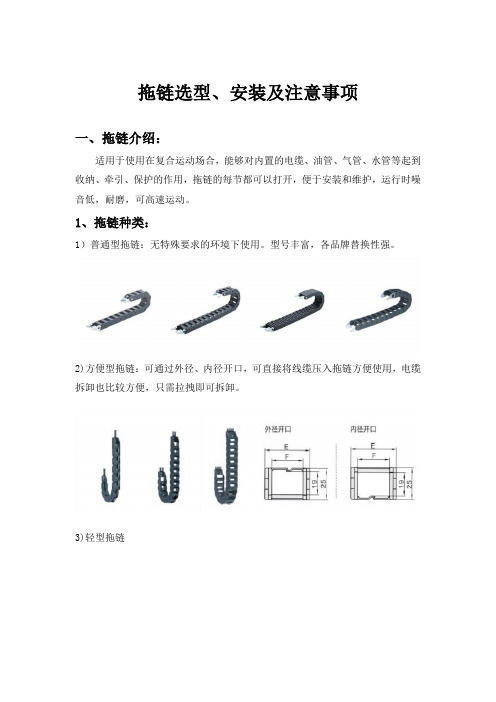
拖链选型、安装及注意事项一、拖链介绍:适用于使用在复合运动场合,能够对内置的电缆、油管、气管、水管等起到收纳、牵引、保护的作用,拖链的每节都可以打开,便于安装和维护,运行时噪音低,耐磨,可高速运动。
1、拖链种类:1)普通型拖链:无特殊要求的环境下使用。
型号丰富,各品牌替换性强。
2)方便型拖链:可通过外径、内径开口,可直接将线缆压入拖链方便使用,电缆拆卸也比较方便,只需拉拽即可拆卸。
3)轻型拖链4)加强型拖链、三维型拖链加强型拖链:可应用于负载较重,长距离、告诉运动、环境恶劣的工况。
三维型拖链:多维运动,小弯曲半径,全封闭防碎屑,链节可拆卸。
2、拖链常用名词解释1、桥式:链节两侧只有横杆连接的结构2、半封闭型:连接一侧封闭,一侧桥式结构,一般为外侧封闭式、内侧为桥式。
3、全封闭式:拖链内外侧均为封闭式结构。
4、打开方式:拖链横杆是否可以打开,方便线缆填装,分为不可打开、内侧开口、外侧开口、内外侧开口。
5、梳状板:用于固定接头处固定管、线,以减少接头处管线的应力。
6、分隔片:用于拖链内部不同类型的管、线。
二、拖链选型1、确定拖链内部尺寸电缆、气管和液压管等负载的数量、类型及直径决定了拖链的内部尺寸和分配状况。
首先,要保证负载的拖链内部合理均匀的分布:包括重量均匀分布,空间合理分布。
若为单一负载且只有一条,空间足够即可(见图一);拖链(图一)若为液压管、水管、气管、油管和电缆等不同的负载最好用竖隔片分隔开来(见图二);若为同种负载数量较多且直径差异比较大,也最好用竖隔片隔开(见图二);拖链(图二)若有多层排布,可用横隔片在高度方向进行分隔(见图三)。
拖链(图三)其次,要保证负载能够在拖链内部能够自由移动,防止排布时产生相互缠绕的现象;然后,根据负载的排布,计算出内高和内宽:通常情况下所选用的拖链的内宽和内高为负载排布的最大高度和最大宽的1.5倍;最后,根据拖链的使用环境决定是否需要选用全封闭拖链(一般情况下在有粉尘颗粒较大或者环境较为恶劣的情况下,为了更好的保护负载,可选用全封闭型的拖链)。
拖链选型手册
拖链选型手册
拖链选型手册:
1.拖链的用途:避免电缆及介质管在运动的过程中与机床相接触。
2.拖链管线排布:管线在拖链中最理想的状态是排成一排,并预留30%的空间,直径差别很大的电缆及介质管应分隔铺设,可采用分隔片实现隔离。
在任何情况下都不允许电缆及介质管在拖链中相互纠缠。
3.电缆或介质管两端都应使用梳状板、电缆夹等去应力元件。
固定电缆最好使用电缆夹。
拖链尽量每一节都能够打开,当高速运动时,一般不选用佳吉的拖链,选用igus的。
电缆选型手册版
电缆的选型与配线选择电线平方数和电流一般铜线安全电流最大为:2.5 平方毫米铜电源线的安全载流量--28A..4 平方毫米铜电源线的安全载流量--35A ..6 平方毫米铜电源线的安全载流量--48A ..10 平方毫米铜电源线的安全载流量--65A..16 平方毫米铜电源线的安全载流量--91A ..25 平方毫米铜电源线的安全载流量--120A..如果是铝线截面积要取铜线的1.5-2 倍..如果铜线电流小于28A;按每平方毫米10A 来取肯定安全..如果铜线电流大于120A;按每平方毫米5A 来取..导线的截面积所能正常通过的电流可根据其所需要导通的电流总数进行选择; 一般可按照如下顺口溜进行确定:十下五;百上二; 二五三五四三倍;七零九五两倍半;铜线升级算.就是10 平方以下的铝线;平方毫米数乘以 5 就可以了;要是铜线呢;就升一个档; 比如 2.5 平方的铜线;就按铝线 4 平方计算.一百以上的都是截面积乘以2; 二十五平方以下的乘以4; 三十五平方以上的乘以3;70 和95 平方都乘以2.5;这么几句口诀应该很好记吧;说明:只能作为估算;不是很准确..另外如果按室内记住电线6 平方毫米以下的铜线;每平方电流不超过10A 就是安全的;从这个角度讲;你可以选择1.5 平方的铜线或2.5 平方的铝线..10 米内;导线电流密度6A/平方毫米比较合适;10-50 米;3A/平方毫米;50-200 米;2A/平方毫米;500 米以上要小于1A/平方毫米..从这个角度;如果不是很远的情况下;你可以选择4 平方铜线或者6 平方铝线..如果真是距离150 米供电不说是不是高楼;一定采用 4 平方的铜线.. 导线的阻抗与其长度成正比;与其线径成反比..请在使用电源时;特别注意输入与输出导线的线材与线径问题..以防止电流过大使导线过热而造成事故..导线线径一般按如下公式计算:铜线:S= IL / 54.4*U`铝线:S= IL / 34*U`式中:I——导线中通过的最大电流AL——导线的长度MU`——充许的电压降VS——导线的截面积MM2说明:1、U`电压降可由整个系统中所用的设备范围内;分给系统供电用的电源电压额定值综合起来考虑选用..2、计算出来的截面积往上靠. 绝缘导线载流量估算铝芯绝缘导线载流量与截面的倍数关系导线截面mm 2 1 1.5 2.5 4 6 10 16 25 35载流是截面倍数9 8 7 6 5 4 3.5 3 2.5载流量A 9 14 23 32 48 60 90 100 123估算口诀:二点五下乘以九; 往上减一顺号走.. 三十五乘三点五; 双双成组减点五.. 条件有变加折算; 高温九折铜升级.. 穿管根数二三四; 八七六折满载流..0.6/1kV单芯低烟无卤耐火电缆DW-NHB-YJE DW-NHA-YJE●0.6/1k两芯低烟无卤耐火电缆DW-NHB-YJE DW-NHA-YJE●0.6/1k三芯低烟无卤耐火电缆DW-NHB-YJE DW-NHA-YJE●0.6/1kV四芯低烟无卤耐火电缆DW-NHB-YJE DW-NHA-YJE●0.6/1kV五芯低烟无卤耐火电缆DW-NHB-YJE DW-NHA-YJE●0.6/1kV三加一芯低烟无卤耐火电缆DW-NHB-YJE DW-NHA-YJE●0.6/1kV三加二芯低烟无卤耐火电缆DW-NHB-YJE DW-NHA-YJE●0.6/1kV四加一芯低烟无卤耐火电缆DW-NHB-YJE DW-NHA-YJE●0.6/1k两芯铠装低烟无卤耐火电缆DW-NHB-YJE23 DW-NHA-YJE230.6/1k三芯铠装低烟无卤耐火电缆DW-NHB-YJE23 DW-NHA-YJE23●0.6/1kV四芯铠装低烟无卤耐火电缆DW-NHB-YJE23 DW-NHA-YJE23●0.6/1kV五芯铠装低烟无卤耐火电缆DW-NHB-YJE23 DW-NHA-YJE23●0.6/1kV三加一芯铠装低烟无卤耐火电缆DW-NHB-YJE23DW-NHA-YJE23●0.6/1kV三加二芯铠装低烟无卤耐火电缆DW-NHB-YJE23 DW-NHA-YJE23●0.6/1kV四加一芯铠装低烟无卤耐火电缆DW-NHB-YJE23 DW-NHA-YJE23常用电工计算口诀第一章按功率计算电流的口诀之一1.用途:这是根据用电设备的功率千瓦或千伏安算出电流安的口诀..电流的大小直接与功率有关;也与电压;相别;力率又称功率因数等有关..一般有公式可供计算;由于工厂常用的都是380/220 伏三相四线系统;因此;可以根据功率的大小直接算出电流..2.口诀:低压380/220 伏系统每KW 的电流;安..千瓦;电流;如何计算电力加倍;电热加半..单相千瓦;4 . 5 安..单相380 ;电流两安半..3. 说明:口诀是以380/220V 三相四线系统中的三相设备为准;计算每千瓦的安数..对于某些单相或电压不同的单相设备;其每千瓦的安数.口诀中另外作了说明..①这两句口诀中;电力专指电动机.在380V 三相时力率0.8 左右;电动机每千瓦的电流约为2 安.即将“千瓦数加一倍” 乘2就是电流; 安..这电流也称电动机的额定电流.例1 5.5 千瓦电动机按“电力加倍”算得电流为11 安..例2 4 0 千瓦水泵电动机按“电力加倍”算得电流为8 0安..电热是指用电阻加热的电阻炉等..三相380 伏的电热设备;每千瓦的电流为1.5安.即将“千瓦数加一半”乘1.5;就是电流;安..例13 千瓦电加热器按“电热加半”算得电流为4.5 安..例21 5 千瓦电阻炉按“电热加半”算得电流为2 3 安..这口诀并不专指电热;对于照明也适用.虽然照明的灯泡是单相而不是三相;但对照明供电的三相四线干线仍属三相..只要三相大体平衡也可以这样计算..此外;以千伏安为单位的电器如变压器或整流器和以千乏为单位的移相电容器提高力率用也都适用..即是说;这后半句虽然说的是电热;但包括所有以千伏安、千乏为单位的用电设备;以及以千瓦为单位的电热和照明设备..例1 1 2 千瓦的三相平衡时照明干线按“电热加半”算得电流为1 8 安..例230 千伏安的整流器按“电热加半”算得电流为45 安..指380 伏三相交流侧例3 3 2 0 千伏安的配电变压器按“电热加半”算得电流为480 安指380/220 伏低压侧..例4100 千乏的移相电容器380 伏三相按“电热加半”算得电流为150 安..②.在380/220伏三相四线系统中;单相设备的两条线;一条接相线而另一条接零线的如照明设备为单相220 伏用电设备..这种设备的力率大多为1;因此;口诀便直接说明“单相每千瓦4.5 安”..计算时; 只要“将千瓦数乘4.5”就是电流; 安..同上面一样;它适用于所有以千伏安为单位的单相220伏用电设备;以及以千瓦为单位的电热及照明设备;而且也适用于220 伏的直流..例1500 伏安0.5 千伏安的行灯变压器220 伏电源侧按“单相每千瓦4.5 安”算得电流为2.3 安..例2 1000 瓦投光灯按“单相千瓦、4.5 安”算得电流为4.5 安..对于电压更低的单相;口诀中没有提到..可以取220 伏为标准;看电压降低多少;电流就反过来增大多少..比如36伏电压;以220 伏为标准来说;它降低到1/6;电流就应增大到6倍;即每千瓦的电流为6 × 4.5=27 安..比如36 伏;60 瓦的行灯每只电流为0.06 × 27=1.6 安;5 只便共有8 安..③在380/220伏三相四线系统中;单相设备的两条线都接到相线上;习惯上称为单相380 伏用电设备实际是接在两条相线上..这种设备当以千瓦为单位时;力率大多为1;口诀也直接说明:“单相380;电流两安半”..它也包括以千伏安为单位的380 伏单相设备..计算时;只要“将千瓦或千伏安数乘 2.5 就是电流;安..例l32 千瓦钼丝电阻炉接单相380 伏;按电流两安半算得电流为80 安..例22 千伏安的行灯变压器;初级接单相380 伏;按电流两安半算得电流为5 安..例321 千伏安的交流电焊变压器;初级接单相380 伏;按电流两安半算得电流为53 安..注1 :按“电力加倍”计算电流;与电动机铭牌上的电流有的有些误差;一般千瓦数较大的;算得的电流比铭牌上的略大些;而千瓦数较小的;算得的电流则比铭牌上的略小些;此外;还有一些影响电流大小的因素;不过;作为估算;影响并不大..注2:计算电流时;当电流达十多安或几十安心上;则不必算到小数点以后;可以四舍五入成整数..这样既简单又不影响实用;对于较小的电流也只要算到一位小数和即可..第二章导体载流量的计算口诀1. 用途:各种导线的载流量安全电流通常可以从手册中查找..但利用口诀再配合一些简单的心算;便可直接算出;不必查表..导线的载流量与导线的载面有关;也与导线的材料铝或铜;型号绝缘线或裸线等;敷设方法明敷或穿管等以及环境温度25度左右或更大等有关;影响的因素较多;计算也较复杂..10 下五;1 0 0 上二..2 5 ;3 5 ;四三界..7 0 ;95 ;两倍半..穿管温度;八九折..裸线加一半..铜线升级算..3.说明:口诀是以铝芯绝缘线;明敷在环境温度25 度的条件为准..若条件不同; 口诀另有说明..绝缘线包括各种型号的橡皮绝缘线或塑料绝缘线..口诀对各种截面的载流量电流;安不是直接指出;而是“用截面乘上一定的倍数”;来表示..为此;应当先熟悉导线截面;平方毫米的排列1 1.5 2.5 4 6 10 16 25 35 50 7O 95 l20 150 185......生产厂制造铝芯绝缘线的截面积通常从而2.5开始;铜芯绝缘线则从1 开始;裸铝线从16 开始;裸铜线从10 开始..①这口诀指出:铝芯绝缘线载流量;安;可以按截面数的多少倍来计算..口诀中阿拉伯数码表示导线截面平方毫米;汉字表示倍数..把口诀的截面与倍数关系排列起来便如下:..10 16-25 35-50 70-95 120....五倍四倍三倍两倍半二倍现在再和口诀对照就更清楚了.原来“10 下五”是指截面从10 以下;载流量都是截面数的五倍..“100 上二”读百上二;是指截面100以上;载流量都是截面数的二倍..截面25与35 是四倍和三倍的分界处.这就是“口诀25、35 四三界”..而截面70、95 则为2.5 倍..从上面的排列;可以看出:除10 以下及100 以上之外;中间的导线截面是每两种规格属同一倍数..下面以明敷铝芯绝缘线;环境温度为25 度;举例说明:例1 6 平方毫米的;按10 下五;算得载流量为30 安..例2150 平方毫米的;按100 上二;算得载流量为300 安..例370 平方毫米的;按70、95 两2 倍半;算得载流量为175安..从上面的排列还可以看出;倍数随截面的增大而减小..在倍数转变的交界处;误差稍大些..比如截面25 与35 是四倍与三倍的分界处;25属四倍的范围;但靠近向三倍变化的一侧;它按口诀是四倍;即100 安..但实际不到四倍按手册为97 安..而35 则相反;按口诀是三倍;即105 安;实际是117 安..不过这对使用的影响并不大..当然;若能胸中有数;在选择导线截面时;25 的不让它满到100 安;35 的则可以略为超过105 安便更准确了..同样;2.5平方毫米的导线位置在五倍的最始左端;实际便不止五倍〈最大可达20安以上;不过为了减少导线内的电能损耗;通常都不用到这么大;手册中一般也只标12 安..②从这以下;口诀便是对条件改变的处理..本句:穿管温度八九折;是指若是穿管敷设包括槽板等敷设;即导线加有保护套层;不明露的按①计算后;再打八折乘0.8若环境温度超过25 度;应按①计算后;再打九折..乘0.9..关于环境温度;按规定是指夏天最热月的平均最高温度..实际上;温度是变动的;一般情况下;它影响导体载流并不很大..因此;只对某些高温车间或较热地区超过25 度较多时;才考虑打折扣.. 还有一种情况是两种条件都改变穿管又温度较高..则按①计算后打八折;再打九折..或者简单地一次打七折计算即0.8 × 0.9=0.72;约0.7..这也可以说是穿管温度;八九折的意思..例如:铝芯绝缘线10 平方毫米的;穿管八折40 安10 × 5× 0.8 =40高温九折45 安10 × 5 × 0.9=45 安..穿管又高温七折35 安1O × 5 × 0.7=3595平方毫米的;穿管八折190安95×2.5×0.8=190高温九折;214 安95 × 2.5 × 0.9=213.8穿管又高温七折..166 安95 × 2.5 × 0.7 =166.3③对于裸铝线的载流量;口诀指出;裸线加一半;即按①中计算后再加一半乘l.5..这是指同样截面的铝芯绝缘线与铝裸线比较;载流量可加大一半..例1 16 平方毫米的裸铝线;96 安16 × 4 × 1.5 =96高温;86 安16 × 4 × 1.5 × 0.9=86.4例2 35 平方毫米裸铝线;150 安35 × 3 × 1.5=157.5例3120 平方毫米裸铝线;360 安120 × 2 × 1.5 =360④对于铜导线的载流量;口诀指出;铜线升级算..即将铜导线的截面按截面排列顺序提升一级;再按相应的铝线条件计算..例一35 平方的裸铜线25 度;升级为50 平方毫米;再按50 平方毫米裸铝线;25 度计算为225 安50 × 3 × 1.5例二16 平方毫米铜绝缘线25 度;按25 平方毫米铝绝缘的相同条件;计算为100 安25 × 4 例三95 平方毫米铜绝缘线25 度;穿管;按120 平方毫米铝绝缘线的相同条件;计算为192 安120 × 2 × 0.8..第三章配电计算一对电动机配线的口诀1.用途根据电动机容量千瓦直接决定所配支路导线截面的大小;不必将电动机容量先算出电流;再来选导线截面..2.口诀铝芯绝缘线各种截面;所配电动机容量千瓦的加数关系:3.说明此口诀是对三相380 伏电动机配线的..导线为铝芯绝缘线或塑料线穿管敷设..4.由于电动机容量等级较多;因此;口诀反过来表示;即指出不同的导线截面所配电动机容量的范围..这个范围是以比“截面数加大多少”来表示..2.5 加三;4 加四6 后加六;25 五120 导线;配百数为此;先要了解一般电动机容量千瓦的排列:0.8 1.1 1.5 2.2 3 4 5.5 7.5 1O 13 17 22 3040 55 75 100“2.5 加三”;表示2.5 平方毫米的铝芯绝缘线穿管敷设;能配“2.5 加三”千瓦的电动机;即最大可配备5.5 千瓦的电动机..“4 加四”;是4 平方毫米的铝芯绝缘线;穿管敷设;能配“4 加四”千瓦的电动机..即最大可配8 千瓦产品只有相近的7.5 千瓦的电动机..“6 后加六”是说从6 平方毫米开始;及以后都能配“加大六”千瓦的电动机..即6 平方毫米可配12 千瓦;10 平方毫米可配16 千瓦;16 平方毫米可配22 千瓦..“25 五”;是说从25 平方毫米开始;加数由六改变为五了..即25 平方毫米可配30 千瓦;35 平方毫米可配40 千瓦;50 平方毫米可配55 千瓦;70 平方毫米可配75 千瓦..“1 2 0 导线配百数” 读“百二导线配百数” 是说电动机大到100 千瓦..导线截面便不是以“加大”的关系来配电动机;而是120 平方毫米的导线反而只能配100 千瓦的电动机了..例17 千瓦电动机配截面为4 平方毫米的导线按“4 加四”例2 17 千瓦电动机配截面为16 平方毫米的导线按“6后加六” ..例3 28 千瓦的电动机配截面为25 平方毫米的导线按“2 5 五”以上配线稍有余裕; 目前有提高导线载流的趋势..因此;有些手册中导线所配电动机容量;比这里提出的要大些;特别是小截面导线所配的电动机..因此; 即使容量稍超过一点如16平方毫米配23千瓦;或者容量虽不超过;但环境温度较高;也都可适用..但大截面的导线;当环境温度较高时;仍以改大一级为宜..比如70 平方毫米本来可以配75 千瓦;若环境温度较高则以改大为95 平方毫米为宜..而100 千瓦则改配150 平方毫米为宜..第四章电力穿管的口诀1. 用途钢管穿线时;一般规定;管内全部导线的截面包括绝缘层不超过管内空截面的40%;这种计算比较麻烦;为此手册中有编成的表格供使用..口诀仅解诀对三相电动机配线所需管径大小的问题..这时管内所穿的是三条同截面的绝缘线..2 口诀: 焊接钢管内径及所穿三条电力线的截面的关系:20 穿4 、625 只穿1040 穿35一二轮流数3.说明:口诀指的是焊接钢管或称厚钢管;管壁厚2 毫米以上;可以埋于地下的..它不同于电线管或称黑铁灯管..焊接钢管的规格以内径表示;单位是毫米.为了运用口诀;应先了解焊接钢管的规格排列:15 20 25 32 40 50 70 80 毫米①这里已经指明三种管径分别可穿的导线截面..其中20毫米内径的可穿4 及6 平方毫米两种截面..另外两种管径只可穿一种截面;即25毫米内径的只可穿10平方毫米一种截面;40 毫米内径的只可穿35 平方毫米一种截面..②“一二轮流数”是什么意思呢这句口诀是解决其它管径的穿线关系而说的..但它较难理解..为此;我们且把全部关系排列出来看一看:从表中可以看出:从最小的管径15 开始;顺着次序;总是穿一种;二种截面;轮流出现..这就是“一二轮流数”..但是;单独这样记忆;可能较困难;如果配合①来记;便会容易些..比如念到“20 穿4、6”后;便可联想到: 20 的前面是15;而且只种穿一种截面;那便是紧挨着的2.5;而20 的后面是25;也只穿一种截面;应该是紧挨着的10..同样;念到“25只穿10”以及“40 穿35”也都可以引起类似的联想..这样就更容易记住了..实际使用时;往往是已知三条电力线的截面;而要求决定管子的规格..这便要把口诀的说法反过来使用..例1 三条70 平方毫米的电力线;应配50 的焊接钢管由“40 穿35”联想到后面的50 必可穿50;70 两种截面 ..例2 三条16 平方毫米的电力线;应配32 的焊接钢管由“25 只穿10”联想到后面; 或由“40 穿35”联想到前面;都可定出管径为32 ..导线穿管时;为了穿线的方便;要求有一定的管径;但在上述的导线和所配的管径下;当管线短或弯头少时;便比管线长或弯头多的要容易些..因此这时的管径也可配小一些..作法是把导线截面视为小一级的;再来配管径..如10 平方毫米导线本来配25毫米管径的管子;由于管线短或弯头少;现在先看成是6 平方毫米的导线;再来配管径;便可改为20 毫米的了.. 最后提一下:“穿管最大240”; 即三条电力线穿管最大只可能达到240 安环境温度25 度..这时已用到150 平方毫米的导线和80 毫米的管径;施工困难;再大就更难了..了解这个数量;可使我们判断:当线路电流大于240安时;一条管线已不可能;必须用两条或三条管线来满足..这在低压配电室的出线回路中; 常有这种现象..第五章三相鼠笼式异步电动机配控保护设备的口诀1.用途根据三相鼠笼式异步电动机的容量千瓦;决定开关及熔断器中熔体的电流安 ..2.口诀三相鼠笼式电动机所配开关;熔体A对电动机容量千瓦的倍数关系:开关起动;千瓦乘6熔体保护;千瓦乘43.说明口诀所指的是三相380 伏鼠笼式电动机..①小型鼠笼式电动机;当起动不频繁时;可用铁壳开关或其它有保护罩的开关直接起动..铁壳开关的容量安应为电动机的“千瓦数的6 倍”左右才安全..这是因为起动电流很大的缘故..这种用开关直接起动的电动机容量;最大不应超过10千瓦;一般以4 . 5 千瓦以下为宜..例1 1.7 千瓦电动机开关起动; 配15 安铁壳开关..例2 5.5 千瓦电动机开关起动;配30 安铁壳开关计算为33 安;应配60 安开关..但因超过30 安不多;从经济而不影响安全的情况考虑; 可以选3 0 安的..例3 7 千瓦电动机开关起动;配60 安铁壳开关..对于不是用来“直接起动”电动机的开关;容量不必按“6 倍”考虑;而是可以小些..②鼠笼式电动机通常采用熔断器作为短路保护;但熔断器中的熔体电流;又要考虑避开起动时的大电流..为此一般熔体电流可按电动机“千瓦数的4 倍”选择..具体选用时;同铁壳开关一样;应按产品规格选用..这里不便多介绍..不过熔丝软铅丝的规格还不大统一;目前仍用号码表示;见表3-1..熔断器可单独装在磁力起动器之前;也可与开关合成一套如铁壳开关内附有容断器..选用的熔体在使用中如出现:“在开动时熔断”的现象;应检查原因;若无短路现象;则可能还是还没有避开起动电流..这时允许换大的一级熔体必要时也可换大两级;但不宜更大..第六章自动开关脱扣器整定电流选择的口诀1.用途根据电动机容量千瓦或变压器容量千伏安直接决定脱扣器额定电流的大小安2.口诀:电动机瞬动;千瓦20 倍变压器瞬动;千伏安3 倍热脱扣器;按额定值3.说明:自动开关常用在对鼠笼式电动机供电的线路上;作不经常操作的开关..如果操作频繁;可加串一个接触器来操作..自动开关可利用其中的电磁脱扣器瞬动作短路保护;利用其中的热脱扣器或延时脱扣器作过载保护..①这句口诀是指控制一台鼠笼式电动机〈三相380 伏的自动开关;其电磁脱扣器瞬时动作整定电流可按”千瓦数的20 倍”选择..例如:10 千瓦电动机;自动开关电磁脱扣器瞬时动作整定电流;为200 安1O × 20有些小容量的电动机起动电流较大; 有时按”千瓦2 0倍”选择瞬时动作整定电流;仍不能避开起动电流的影响;这时允许再略取大些..但以不超过20% 为宜..②这句口诀指配电变压器后的;作为总开关用的自动开关..其电磁脱扣器瞬时动作整定电流安;可按“千伏安数的3 倍”选择..例如:500 千伏安变压器;作为总开关的自动开关电磁脱扣器瞬时动作整定电流为1500 安500 × 3..③对于上述电动机或变压器的过负荷保护;其热脱扣器或延时过电流脱扣器的整定电流可按电动机或变压器的额定电流选择..如10 千瓦电动机;其整定电流为20 安;40 千瓦电动机;其整定电流为80 安..如500 千伏安变压器;其整定电流为750 安..具体选择时;也允许稍大些..但以不超过20% 为宜..第七章车间负荷1. 用途根据车间内用电设备容量的大小千瓦;估算电流负荷的大小安;作为选择供电线路的依据..冷床50 ;热床75 ..电热120;其余150..台数少时;两台倍数;几个车间;再0 . 3 处..2.口诀按机械工厂车间内不同性质的工艺设备;每100 千瓦设备容量给出相应的估算电流..3.说明口诀是对机械工厂不同加工车间配电的经验数据..适用于三相380 伏..车间负荷电流在生产过程中是不断变化的..一般计算较复杂..但也只能得出一个近似的数据..因此; 利用口诀估算;同样有一定的实用价值;而且比较简单..为了使方法简单;口诀所指的设备容量千瓦;只按工艺用电设备统计统计时;不必分单相;三相;千瓦或千伏安等..可以统统看成千瓦而相加 ..对于一些辅助用电设备如卫生通风机、照明以及吊车等允许忽略;因为在估算的电流中已有适当余裕;可以包括这些设备的用电..有时;统计资料已包括了这些辅助设备..那也不必硬要扣除掉..因为它们参加与否; 影响不大..口诀估出的电流;是三相或三相四线供电线路上的电流..下面对口诀进行说明:①这口诀指出各种不同性质的生产车间每100 千瓦设备容量的估算电流安 ..“冷床50”;指一般车床;刨床等冷加工的机床;每100 千瓦设备容量估算电流负荷约50 安..“热床7 5”指锻、冲、压等热加工的机床; 每1 0 0 千瓦设备容量估算电流负荷约75 安.. “电热1 2 0 ”读“电热百二” 指电阻炉等电热设备;也可包括电镀等整流设备;每100 千瓦设备容量;估算电流负荷约120 安..“其余150” 读“其余百五”指压缩机;水泵等长期运转的设备;每100 千瓦设备容量估算电流负荷约l50 安..例1 机械加工车间机床容量等共240 千瓦;则估算电流负荷为240 ÷ 100× 50=120 安例2 锻压车间空气锤及压力机等共180 千瓦;则估算电流负荷为180 ÷100× 75=135 安例3 热处理车间各种电阻炉共280 千瓦;则估算电流负荷为280 ÷ 100×12O =336 安电阻炉中有一些是单相用电设备; 而且有的容量很大..一般应平衡分布于三相中;若做不到;也允许有些不平衡..如果很不平衡;最大相比最小相大一倍以上时;则应改变设备容量的统计方法;即取最大相的千瓦数乘3..以此数值作为车间的设备容量;再按口诀估算其电流..例如某热处理车间三相电阻炉共120 千瓦平均每相40 千瓦;另有一台单相50 千瓦;无法平衡;使最大一相达50+40=90 千瓦..这比负荷小的那相大一倍以上..因此;车间的设备容量应改为90 × 3=270千瓦;再估算电流负荷为270 ÷ 100× 120=324 安..例4 空压站压缩机容量共225 千瓦;则估算电流负荷为225 ÷ 100× 150=338 安..对于空压站;泵房等装设的备用设备;一般不参加设备容量统计..某泵房有5台28 千瓦的水泵;其中一台备用;则按4 × 28=112 千瓦计算电流负荷为168 安..估出电流负荷后;可根据它选择送电给这个车间的导线规格及截面..这口诀对于其它工厂的车间也适用..其它生产性质的工厂大多是长期运转设备; 一般可按“其余1 5 0 ”的情况计算..也有些负荷较低的长期运转设备;如运输机械皮带等;则可按“电热1 2 0 ”采用..机械工厂中还有些电焊设备;对于附在其它车间的少数容量不大的设备;同样可看作辅助设备而不参加统计..若是电焊车间或大电焊工段;则可按“热床75”处理;不过也要注意单相设备引起的三相不平衡..这可同前面电阻炉一样处理..。
拖链选型指导书

拖链选型指导书序号修改内容概述修改人修改日期备注年—月—日拖链设计指导书一:拖链的用途纠正:电缆及介质管扎成一捆是错误的使用方法。
拖链适合于使用在往复运动距离较大的场合,能够对内置的电缆、油管、气管、水管等起到牵引和保护作用。
电缆及介质管在运动的过程中,允许的弯曲半径不同,使用拖链可以将不同弯曲半径的电缆及介质管统一在拖链的弯曲半径上,保护大弯曲半径的电缆及介质管。
拖链可以避免电缆及介质管在运动的过程中与机床相接触。
二:拖链管线排布管线在拖链中最理想的状态是排成一排,并预留30%的空间(可能后增加电缆及介质管),直径差别很大的电缆及介质管应分隔铺设,可采用分隔片实现隔离。
在任何情况下都不允许电缆及介质管在拖链中相互纠缠。
电缆或介质管重量应该沿着拖链宽度方向对称分布,使用不同外保护套材料的电缆及介质管不得相互接触。
电缆及介质管两端都应使用梳状板,电缆夹等去应力元件。
固定电缆最好使用电缆夹。
拖链中的竖隔片、横隔片可以将不同种类及保护材料的电缆及介质管分隔开,(豪森要求,基本要将气管,强电电缆,弱电电缆分隔开)避免它们在拖链内部之间的相互摩擦。
拖链尽量每一节都能够打开(不能打开的拖链,客户一般不允许使用)。
当高速运动时,一般不选用佳吉的拖链。
选用igus的。
1、拖链的安装形式:水平,垂直(立式,挂式),侧向安装,旋转运动2、受力曲线图:三:拖链的选型1、选型步骤:确定安装方式(悬空、垂直、侧面、旋转等运动)确定行程长度确定拖链的尺寸(根据机器设备具体安装空间与装填物如:电缆数目/电缆外径,分隔方式,确定拖链尺寸—内高、内宽、弯曲半径,拖链长度,节数)校核架空长度及负载(是否在建议采用的应用范围)确定打开方式(一侧打开、两侧打开、沿内径快速打开、沿外径快速打开等)确定分隔片数量确定去应力紧固装置形式(电缆夹,梳状板)3、拖链的选型原则:内高:选择内置电缆、油管、气管、水管等中直径最大的一根定作D,拖链的内高为hi,则hi=1.1D。
Siemens 可伸缩电缆及拖链类电缆产品说明书

Cable Selection Guidefor Industrial Automation Motor, servo, and feedback cablesSingle core · Control cablesData cables · Bus cablesIndustrial Ethernet cablesIncludes page referencesIn our two German plants, using the latest production methods, we manu-facture approximately one million conductor kilometers (= 77 times around the world) each year . More than 300 qualified employees are specialized in the production of high-quality standard and specialty cables. Through use of the latest materials and collaboration with international test institutes, we drive innovation in the areas of automation, data technology , building system technology , and renewable energy.Since 2014, in a 7,000 m² facility in the Chinese city of Taicang (approx. 50 km northwest of Shanghai) HELUKABEL ® has been producing cable and wi-res, primarily for the Asian region. As in the German plants, the focus here is also on high-quality , flexible and highly flexible cables and wires that are manufactured in accordance with Chinese and international standards. Theuse of flexible manufacturing cells enable short delivery times.PRODUCTIONWe specialize in the production of high-quality cables and wires.RESEARCH & DEVELOPMENTWe develop optimal, customized cable solutions for our customers.Research and development are the foundation of our work and are an impor-tant engine for growth. In interdisciplinary teams we continuously develop our products and seek to enhance them for multiple applications. Moreover , we rely on customer feedback as well as cooperation with regional colleges and research institutes.The materials that will be used are an important starting point of our work. In this regard, we place as much emphasis on searching for and utilizing new materials as we do on manufacturing our plastic mixtures (granulates) our-selves, in order to enhance mechanical properties, such as oil resistance, temperature range or chemical compatibility. Furthermore, we are capable of pulling a majority of our copper ourselves, and thus ensure a uniform, high quality relative to properties and workmanship.By continuously optimizing our manufacturing processes and procedures, we have become more efficient and economical, and yet we are still able to take the complex requirements of a wide variety of applications (such as cables for industrial robots or for applications under cleanroom conditions) into account.A crucial stage in the development process of our products is the work done in our Test Centre. For example, cables suitable for drag chain implementati-on can be tested with acceleration up to 10 G. Temperature ranges from -50°C to +250°C are simulated in a special climate device so that drag chain cables can be tested for series production readiness before they are installed in applications like refrigerated warehouses or steel mills.Our test facilities:· T est systems for bending and torsion requirements· D rag chain test systems with movement distances from 1 m, 3 m, 5 m, 6 m, 18 m, and 40 m · Fire testing systems · Abrasion testing systems· T orsion test tower for wind turbines· A ging ovens in accordance with UL, VDE, CSA, HAR, TÜV , CCCContentI. F lexible cables for fixed installation or occasional movements a. Control cables b. Data cables c. Single coresd. Motor & Servo cablese. Feedback cablesf. PROFInet / Industrial Ethernetg. BUS cablesII. H ighly flexible cables for continuous movements, such as drag chains a. Control cables b. Data cables c. Single coresd. Motor & Servo cablese. F eedback cablesf. PROFInet / Industrial Ethernetg. BUS cables4-56-76-78-98-910-1110-13NotesDrag chain classred Halogen-free cablesgreen Bio-oil & microbe-resistant cables blue Intrinsically safe cablesdrag chain values can be found in Version 27 of the Cables, Wires and Accessories catalogue.*Oil resistance1. Are you looking for a flexible cable for fixed installationor occasional movements (page 4) or a highly flexible cable for continuous movements (page 14) such as a drag chain? 2. W hat kind of cable do I need (control cable,data cable, servo cable, BUS cable, ...)?3. What kind of sheath material?4. Screened or unscreened?5. Without UL/CSA, with UL/CSA or according to NFPA 79?14-1516-1716-1718-1918-1920-2120-23Industrial cablesOur logistics center - Hemmingen/Stuttgart· 40,500 Euro-pallet racks 16 aisles with 16 storage and retrieval devices· 35,900 bin locations in the automatic small parts warehouse capacity: 1,000 bins per hour· 670 storage spaces in the heavy load warehouse: Reels to max. 4,000 kg and 2.20 m diameter · 2 km conveyor line for pallets· C onveyer connection directly to the length-cutting machines · Manual processes reduced to merely packing Infrastructure cablesOur logistics centre - Neuenhagen/Berlin · 11,000 cable reels in stock· A utomatic processing of reels to 2.80 m Ø and 10 t · 10 rewinding machines· Cut to length with state-of-the-art 1,200 mm² cutting tools · 24 h delivery is possibleOur production in numbers:· 40,000 m² production area · 23 extruder systems · 19 stranding machines · 50 braiding machines· Cables & wires from 0.05 to 1,000 mm²· M anufacturing in accordance with: VDE, EAC (GOST-R), UL, CSA, HAR, CCC, Germanischer Lloyd, TÜV or customerspecificationLOGISTICSCable industry logistics redefined.Continue: PRODUCTIONAt its corporate headquarters in the Swabian town of Hemmingen, HELUKABEL ® operates Europe's largest distribution centre for cables and wires. This is where a majority of the more than 33,000 products are housed in a 160,000m² storage area. Through the use of state-of-the-art conveyor and control technology , more than 1,000 orders can be picked and shipped daily to destinations around the world.Neuenhagen/Berlin is the central warehouse location for underground cable, medium-voltage cable, and other infrastructure cables. Storage capacities ofmore than 5,000 m² in the warehouse and 50,000 m² outdoors enable fast deliveries of cable, configured from 1 – 30 kV , to construction sites and major projects.The patented heavy load length-cutting machines with more than 10 tons of load capacity are the largest of their type in Germany.The new logistics centre at the Taicang (China) production facility serves as aproduct distribution hub for the Asian region, and offers incredible advanta-ges, particularly for servicing time-critical and volume-critical major projects.CONTROL CABLE |Flexible cables for fixed installation or occasional movementsFlexible cables for fixed installation or occasional movementsDATA CABLES | Flexible cables for fixed installation or occasional movementsFlexible cables for fixed installation or occasional movementsMOTOR AND SERVO CABLES | Flexible cables for fixed installation or occasional movementsEnergy drag chains · O pen chains · C losed chains · A ccessories· I nstallation instructions · S election tablesYOU WILL FIND ADDITIONAL Energy drag chainsREXROTH AG and are intended exclusively for comparative purposes. LENZE … are registered trademarks of LENZE AG and are intended exclusively for comparative purposes.Flexible cables for fixed installation or occasional movementsBundling, binding, and fastening · P lastic helix · Cable tie · V elcro fastener · Mounting baseYOU WILL FIND ADDITIONAL Bundling, binding, and fastening* Extremely oil resistant: Please contact us first for special applications.PROFINET / INDUSTRIAL ETHERNET |Flexible cables for fixed installation or occasional movementsBUS CABLES | Flexible cables for fixed installation or occasional movements11Flexible cables for fixed installation or occasional movementsAUR = A vailable upon request, or refer to the "Data, Network and BUS Technology" catalogue12BUS CABLES |Flexible cables for fixed installation or occasional movementsFlexible cables for fixed installation or occasional movementsAUR = A vailable upon request, or refer to the"Data, Network and BUS Technology" catalogue1314CONTROL CABLE |Highly flexible cables for continuous movements, such as drag chainsCable glandsCable glandsFor standard applications:· Plastic · Stainless steelFor specific applications:· Electromagnetic compatibility · Robust applications · Increased temperature · Hazardous area· S pecial pressure & installation condi-tionsYOU WILL FIND ADDITIONAL ACCESSORIES IN THE CABLE ACCESSORIES CATALOGUE!* Extremely oil resistant: Please contact us first for special applications.15Highly flexible cables for continuous movements, such as drag chainsToolsTools · Cable shear· D ismantling/stripping · Crimping/Pressing · S hield-Kon tools · F astening · C able tie tools · Handling · M ountingYOU WILL FIND ADDITIONAL ACCESSORIES IN THE CABLE ACCESSORIES CATALOGUE!* Extremely oil resistant: Please contact us first for special applications.16DATA CABLES | Highly flexible cables for continuous movements, such as drag chainsInsulated, shrink, braided, and temperature protection tubesInsulated, shrink, braided, and tem-perature protection tubes · I nsulation tubes · H eat shrink tubing · B raided hose· H igh-temperature protection · E nd capsYOU WILL FIND ADDITIONAL ACCESSORIES IN THE CABLE ACCESSORIES CATALOGUE!17Highly flexible cables for continuous movements, such as drag chainsCore end sleeves and cable lugs · Core end sleeves · Shield connectors · Solderless terminals · T ubular cable lugs · Compression jointsYOU WILL FIND ADDITIONAL ACCESSORIES IN THE CABLE ACCESSORIES CATALOGUE!Core end sleeves and cable lugsMOTOR and SERVO CABLES | Highly flexible cables for continuous movements, such as drag chainsThis sensational, quick fas-tening connector is safe and stable while saving time and installation costs. The vibrati-on resistant lock mechanism was perfected for plug con -nectors sizes M17, M23 and M40, which can be found in the HELUTEC ® series 617, 917, 623, 723, 923 and 940. TheHELUTEC ®angle junction boxes can be easily combined at any time with the HELUTEC ® sys-tem or with standard lock nuts. This also addresses the issue of downward compatibility.Slide it on and rotate for a tight fit. Patented perfection inclu -ded.Fits in tight locations. In areas with limited space, just wind the pre-tensioned lock nut be -fore sliding the nut into the lock position. A small rotation with a little pull at the plug releases the lock nut preventing an un -intended release of the vibrati-on resistant quick fastener. Only a quarter turn and a slight pull on the connector is required to disconnect. The connection is absolutely vibration proof. This was specially developed and pa -tented for the HELUTEC ® series 615/915.Bonded for life. This overmolded connector consists of a housing and the overmold, which are bonded together and cannot be disassembled. This provides the required manipulation security for customized units - a design that is normally only available for cast versions. All commer-cially available cables at any length can be connected to the inner section of the robust metal housing. This is for both options: Standard screw connections or those items that include a paten -ted fast lock system. For almost any pin design.The innovative HELUTEC ® systemThe Patented Special Development for the HELUTEC ® Series 615/915The freely customizable connector18HELUTEC ® SIGNAL AND POWER PLUG CONNECTORS * Extremely oil resistant: Please contact us first for special applications.Siemens 6FX5008…, Siemens 6FX8008Plus… are registered trademarks of SIEMENS AG and are intended exclusively for comparative purposes. INDRAMAT INK… are registered trademarks of BOSCH REX -ROTH AG and are intended exclusively for comparative purposes. LENZE … are registered trademarks of LENZE AG and are intended exclusively for comparative purposes.Stable, versatile, safe: HELUTEC ® series can be found where a safe connection is required within a limited installation space. The plug connectors in the 617, 623 and 627 series are designed especially for extra-low voltages, and are used in any applica -tion that transmits signals, controls motors or mo-nitors the smooth functioning of a system.For this purpose, a multitude of multi-pin insula -tion bodies - matching a variety of different de-signs such as plugs, couplings and flush-mounted boxes - are available for the user. Consequently, HELUTEC ® engineers are able to handle a multi-tude of customer-specific connector requirements in a very innovative way.Extremely resilient: HELUTEC ® power plug connec -tors accelerate torque heavy drive motors, spindle drives and servo motors reliably up to the highest rotational speeds while tolerating millions of ab -rupt starts and stops. Voltages up to 630 V and currents of up to 200 A are transferred reliably even in continuous operation and under the most demanding conditions. Cable cross sections of up to 50 mm² and the smallest possible designs are - depending on the application - part of the scope of delivery as well as a perfect EMC shielding for the highest operational and work safety.Strong vibrations and sudden stops have no impact on these plug connectors in day-to-day operationsHELUTEC ®-Serie 617 / 623 / 627HELUTEC ®-Serie 917 / 923 / 932 / 940 / 958Signal connectors – Controlling – MonitoringPower plug connectors – Strong and Safe19Highly flexible cables for continuous movements, such as drag chainsOnline configurator: www.helutec.de* Extremely oil resistant: Please contact us first for special applications.20PROFINET / INDUSTRIAL ETHERNET | Highly flexible cables for continuous movements, such as drag chainsBUS CABLES |Highly flexible cables for continuous movements, such as drag chainsD E V I C E N E TO i l -r e s i s t a n t P U RI n d o o rCables are only available with UL/CSA standard; shown on the opposite column, right pageA S -I N T E R F A C EO i l -r e s i s t a n t P U RI n d o o rCables are only available with UL/CSA standard; shown on the opposite column, right page**Dragchainclassesareavailableonrequest(****************).Highly flexible cables for continuous movements, such as drag chains* Extremely oil resistant: Please contact us first for special applications.**Dragchainclassesareavailableonrequest(****************).AUR = A vailable upon request, or refer to the "Data, Network and BUS Technology" catalogue2122S a f e t y B U SP U RI n d o o rCables are only available with UL/CSA standard; shown on the opposite column, right pageBUS CABLES |Highly flexible cables for continuous movements, such as drag chainsEnd caps & core end sleevesCable protection tube systemsEnd caps & Core end sleeves for · T elecommunication cables · L ow-voltage · M edium-voltage· A ccessories/component partsYOU WILL FIND ADDITIONAL ACCESSORIES IN THE CABLE ACCESSORIES CATALOGUE!Cable protection tube systems Corrugated tubes:· F or standard applications · Oversized· Dividable corrugated tubes:Highly flexible cable tubes · P lastic with coil springs · Metal, spiral wound Cable protection tubes for heavy duty applications YOU WILL FIND ADDITIONAL ACCESSORIES IN THE CABLE ACCESSORIES CATALOGUE!* Extremely oil resistant: Please contact us first for special applications.**Dragchainclassesareavailableonrequest(****************).23**110 OHM SafetyBUS PUR yellow 3x0,75 CMXyesno800652-30°C to +80°C758nono7,8 mmyesHighly flexible cables for continuous movements, such as drag chainsNOTESPricesErrors excepted. All prices are subject to change and without obligation Technical modifications© HELUKABEL ® GmbH HemmingenDimensions and specifications may change without prior notice. Consequently all illustrations, numerical data, etc. are provided without guarantee. Colour devia -tions between photos and delivered goods cannot be avoided. Reproduction or duplication of the text and illustrations, in whole or in part, remain reserved. The transfer of copyrights requires the written consent of HELUKABEL ® GmbH. Our General Terms of Delivery and Payment, which can be viewed at www.helukabel.de, apply.Safety noticeThe cables and wires described in the brochure are produced in accordance with national and international standards, as well as plant standards; application safety , as stipulated in safety directives, standards, and statutory regulations, as amended, are provided. Following proper installation and usage guidelines, the possibility of product-specific dangers can be excluded. This brochure describes general use information for each product. Independent of the above, the applicable DIN VDE specifications apply. Installation and processing must only be executed by qualified electricians.Our General Terms of Delivery and Payment, which can be viewed at www.helukabel.de, apply* Extremely oil resistant: Please contact us first for special applications.**Dragchainclassesareavailableonrequest(****************).Logistics-Centre Hemmingen / StuttgartHELUKABEL ® GmbH .Headquarters . Dieselstrasse 8-12 . 71282 Hemmingen. Germany . Phone: +49 (0)7150 9209-0 .*****************W M /C a b l e f i n d e r /03.2016/2000/E N /W D。
电缆选型手册簿及常用公式
电缆的选型与配线选择电线平方数和电流一般铜线安全电流最大为:2.5 平方毫米铜电源线的安全载流量--28A。
4 平方毫米铜电源线的安全载流量--35A 。
6 平方毫米铜电源线的安全载流量--48A 。
10 平方毫米铜电源线的安全载流量--65A。
16 平方毫米铜电源线的安全载流量--91A 。
25 平方毫米铜电源线的安全载流量--120A。
如果是铝线截面积要取铜线的 1.5-2 倍。
如果铜线电流小于 28A,按每平方毫米 10A 来取肯定安全。
如果铜线电流大于 120A,按每平方毫米 5A 来取。
导线的截面积所能正常通过的电流可根据其所需要导通的电流总数进行选择,一般可按照如下顺口溜进行确定:十下五,百上二, 二五三五四三倍,七零九五两倍半,铜线升级算.就是 10 平方以下的铝线,平方毫米数乘以 5 就可以了,要是铜线呢,就升一个档, 比如 2.5 平方的铜线,就按铝线 4 平方计算.一百以上的都是截面积乘以 2, 二十五平方以下的乘以 4, 三十五平方以上的乘以 3, 70 和 95 平方都乘以 2.5,这么几句口诀应该很好记吧,说明:只能作为估算,不是很准确。
另外如果按室内记住电线 6 平方毫米以下的铜线,每平方电流不超过 10A 就是安全的,从这个角度讲,你可以选择 1.5 平方的铜线或 2.5 平方的铝线。
10 米内,导线电流密度 6A/平方毫米比较合适,10-50 米,3A/平方毫米,50-200 米,2A/平方毫米,500 米以上要小于 1A/平方毫米。
从这个角度,如果不是很远的情况下,你可以选择 4 平方铜线或者 6 平方铝线。
如果真是距离 150 米供电(不说是不是高楼),一定采用 4 平方的铜线。
导线的阻抗与其长度成正比,与其线径成反比。
请在使用电源时,特别注意输入与输出导线的线材与线径问题。
以防止电流过大使导线过热而造成事故。
导线线径一般按如下公式计算:铜线: S= IL / 54.4*U`铝线: S= IL / 34*U`式中:I——导线中通过的最大电流(A)L——导线的长度(M)U`——充许的电压降(V)S——导线的截面积(MM2)说明: 1、U`电压降可由整个系统中所用的设备范围内,分给系统供电用的电源电压额定值综合起来考虑选用。
- 1、下载文档前请自行甄别文档内容的完整性,平台不提供额外的编辑、内容补充、找答案等附加服务。
- 2、"仅部分预览"的文档,不可在线预览部分如存在完整性等问题,可反馈申请退款(可完整预览的文档不适用该条件!)。
- 3、如文档侵犯您的权益,请联系客服反馈,我们会尽快为您处理(人工客服工作时间:9:00-18:30)。
低烟无卤外护套拖链系统对绞屏蔽控制电缆
应用范围
低烟无卤外护套拖链系统对绞屏蔽控制电缆应用于高要求的运动场合,军工医院设备常用。
DUUSP电缆的特点
1.高柔抗拉
2.弯曲半径8倍电缆直径
3.防油污防日照防老化耐水碱等
4.保证工作的连续性
5.用于拖链系统大于600万次循环使用
电缆结构
导体材料:多股精绞成束裸铜丝。
导体结构:符合VDE类标准。
芯线绝缘:DVV混合料,抗撕裂,抗切割。
芯线绞合:芯线小节距绞合,对绞成缆。
芯线标识:红黄绿双。
屏蔽:镀锡铜丝屏蔽,屏蔽覆盖率85%以上。
外护套:低烟无卤聚氨酯。
耐磨抗拉。
技术指标
最小弯曲半径:8×电缆外径。
温度范围:-45℃~+80℃。
工作电压:450/700V
测试交流电压:2000~3000V。
执行标准:符合VDE、GB。
