TM1914D-RGB8断点续传5050灯珠规格书
5050白光LED灯珠规格书
深圳市鑫冠明科技有限公司SHAN ZHEN SHI XIN GUAN MINGCustomer :Part No : 5050-03-WWWCDeveloped No :Date:CUSTOMER APPROVED BYAPPROVED Q.C. R&D深圳市鑫冠明科技有限公司_______________________________________________________________■ Outline Dimension:213456123456■ View Angle:Notes:1. All dimensions are in millimeters.2. Tolerance is ±0.2 unless otherwise noted.3. Specifications are subject to change without notice.SPATIAL DISTRIBUTION0.60.80.31.00.520°0°10°30°40°50°60°70°80°90°深圳市鑫冠明科技有限公司Typical Electrical & Optical Characteristics(Ta=25°)Items Symbol Condition Device Min Typ Max UnitForward Voltage VF I F =20mA Chip1 3.0 3.4 V Chip2 3.0 3.4 V Chip3 3.0 3.4 VReverse Current IR VR =5V Chip1 --- --- 5 μA Chip2 --- --- 5 μA Chip3 --- --- 5 μATC(K)I F =20mAChip1 6000 6500 KChip2Chip3I F =20mAChip1 6000 6500 KChip2Chip3Luminous Intensity Iv I F =20mA Chip16300 7000mcd Chip2 mcd Chip3 mcdView Angle 2θ1/2I F =20mA --- 120 --- Deg■Absolute Maximum Ratings (Ta = 25℃)Items Symbol Absolute maximum Rating Unit Power Dissipation P D 120 mWForward Current(DC) I F 30 mAPeak Forward Current I FP 150 mA Reverse Voltage V R 5 V Operation Temperature Topr ﹣40~﹢85 ℃Storage Temperature Tstg ﹣40~﹢85 ℃深圳市鑫冠明科技有限公司Note :1/10 Duty Cycle ,0.1 ms Pulse Width.■ Typical Electrical/Optical Characteristics Curves:3.24.05040302010 3.63.22.82.402.090804.23.83.43.0604020-40-202.62.22.52.01.51.00.55040302010504030201010080604002090802.52.01.51.00.5604020-40-207506505504503501.21.00.20.80.60.4Wavelength Vs. Relative Intensity深圳市鑫冠明科技有限公司ClassificationTest ItemTest ConditionsDurationUnits Tested Number of Damaged Life Test Operating Life Test Ta =25℃±5℃,RH=55±20%RH, IF=30mA 1000hrs 22 0/22 EnvironmentTestHigh Temperature Storage Ta =100℃±10℃ 1000hrs 22 0/22 Low Temperature Storage Ta =﹣40℃+3-5℃ 1000hrs 22 0/22 Temp &Humidity StorageTa =85℃+5-3 ℃ RH=85 + - 510 %RH 1000hrs 220/22Thermal Shock TestTa=﹣40℃+5-3℃~100℃+3-5 ℃ T=5min - 5min 100 Cycles22 0/22Temperature Cycling TestTa=﹣40+3-5 ℃~25℃~100+5-3℃~25℃ T=30min-5min-30min- 5min10Cycles 22 0/22深圳市鑫冠明科技有限公司深圳市鑫冠明科技有限公司TAPE312456。
5050参数
mcd、流明瓦、照度的解释流明瓦”:单位时间光源向空间发出的使人产生光感觉的能量称为“光通量”,其单位就是“流明”。
“流明瓦”是“流明/瓦”的读法,是指光源所发出的光通量与它所消耗的电功率之比,即光源的发光效率。
“mcd”:光通量的空间密度,即单位立体角的光通量,叫发光强度,是衡量光源发光强弱的量,其中文名称为“坎德拉”,符号就是“cd”。
前面那个“m”是词头,是千分之一的意思(就像长度单位,中文名称为“米”,其符号为“m”,前面再加一个“m”成为“mm”,就变成千分之一米,也就是毫米了),所以“mcd”的中文读法为“毫坎德拉”。
“照度”:是指被光源照亮的物体,其单位面积上通过的光通量,通俗地说,就是物体被照亮的程度。
单位是“勒克斯”,其符号为“Lx电压流明功率防水否以及封装类型5050 60灯12V 828LM 14.4W 有滴胶防水,套管防水及防水级别更高的全套管防水3528 60灯12V 240LM 4.8W 有滴胶防水,套管防水及防水级别更高的全套管防水电源参数:12V直流,5050的灯条要用1.5或者2.0A.3528灯条要用1.0A 的就可以了.安装条件和注意事项:安装前物体表面清洁干净,干燥,平整. 灯条背面贴了3M粘胶即可直接粘贴.A类工艺超低光衰LED白光。
此款LED白灯自从2009年2月5日开始老化以来,截至2009年05月28日止,超过2000小时的光衰记录是0%以内光衰。
详细情况如下:1000小时:-4%光衰,2000小时:-1%光衰,外形尺寸:50*50mm贴片光电特性参数:电流越大,电压越高,温度越高,电流越小,发光角度:125度等,正向电流最大不能超过60mA,反向电压最大不能超过5V,工作温度在-35~+60℃之间最好.如果不考虑光衰寿命问题,也可在+85度以下工作,功率:0.18W(与市面上号称0.2W的相同功率),最大承受脉冲电流:250mA, 焊接温度:260±5℃。
5050发光二极管 MHBBWT-0000-000COHD230G 规格书(V1.1)

.C R E E .C o m /X L A m pCLD-DS146 Rev 1Cree ® XLamp ® MHB-B LEDsProDuCt DEsCriPtionThe XLamp® MHB-B LeD is a new high-power LeD that enables a more effective way to lower system costs for high lumen lighting applications, such as high-bay, roadway and outdoor area, than mid-power LeDs.Leveraging key elements of Cree’s SC5 Technology™ Platform, the ceramic MHB-B LeDs combine high light output, high efficacy and high reliability to enablehigh lumen LeD designs that are not possible with mid-power LeDs.The MHB-B LeD delivers higher LPW than the MHB-A LeD in the same 5mm x 5mm package, allowing lighting manufacturers to quickly increase performance for existing MHB designs without any additional investment.FEAturEs• Flexible 9-v, 18-v or 36-v options • Maximum drive current: 700 mA (9 V), 350 mA (18 V), 175 mA (36 V)• viewing angle: 115°• Available in 70-CRI, 80-CRI and 90-CRI options• Unlimited floor life at ≤ 30 ºC/85% RH • Reflow solderable - JEDEC J-STD-020C• electrically neutral thermal path • RoHS- and ReACh-compliant• UL ® recognized component (E349212)tABLE oF ContEntsCharacteristics ...........................................2Flux Characteristics, easyWhite ® Order Codes and Bins - 9 V ..................................3Flux Characteristics, easyWhite ® Order Codes and Bins - 18 V ................................5Flux Characteristics, easyWhite ® Order Codes and Bins - 36 V ................................7Relative Spectral Power Distribution ........9Relative Flux vs. Junction Temperature ....9electrical Characteristics .........................10Relative Flux vs. Current ..........................11Relative Chromaticity vs. Current ............13Relative Chromaticity vs. Temperature ...14Typical Spatial Distribution . (14)Thermal Design ........................................15Performance Groups – Luminous Flux ..16Thermal Design - Continued ....................16Performance Groups – Chromaticity ......17Cree’s Standard White Chromaticity Regions Plotted on the 1931 CIe Curve ..18Bin and Order Code Formats ...................19Reflow Soldering Characteristics ............20Notes ........................................................21Mechanical Dimensions .. (23)Tape and Reel ...........................................24Packaging . (25)CHArACtEristiCsFLuX CHArACtEristiCs, EAsyWHitE® Order COdes and Bins - 9 VThe following table provides order codes for XLamp MHB-B LeDs. For a complete description of the order code nomenclature, please see the Bin and Order Code Formats section (page 18).Notes• Cree maintains a tolerance of ±7% on flux and power measurements, ±0.005 on chromaticity (CCx, CCy) measurements and a tolerance of ±2 on CRI measurements. See the Measurements section (page 21).• Cree XLamp MHB-B LED order codes specify only a minimum flux bin and not a maximum. Cree may ship reels in flux bins higher than the minimum specified by the order code without advance notice. Shipments will always adhere to the chromaticity bin restrictions specified by the order code.* Flux values @ 25 °C are calculated and for reference only.Notes• Cree maintains a tolerance of ±7% on flux and power measurements, ±0.005 on chromaticity (CCx, CCy) measurements and atolerance of ±2 on CRI measurements. See the Measurements section (page 21).• Cree XLamp MHB-B LED order codes specify only a minimum flux bin and not a maximum. Cree may ship reels in flux bins higher thanthe minimum specified by the order code without advance notice. Shipments will always adhere to the chromaticity bin restrictions specified by the order code.*Flux values @ 25 °C are calculated and for reference only.FLuX CHArACtEristiCs, EAsyWHitE ® Order COdes and Bins - 9 V - COntinuedFLuX CHArACtEristiCs, EAsyWHitE® Order COdes and Bins - 18 VThe following table provides order codes for XLamp MHB-B LeDs. For a complete description of the order code nomenclature, please see the Bin and Order Code Formats section (page 18).Notes• Cree maintains a tolerance of ±7% on flux and power measurements, ±0.005 on chromaticity (CCx, CCy) measurements and a tolerance of ±2 on CRI measurements. See the Measurements section (page 21).• Cree XLamp MHB-B LED order codes specify only a minimum flux bin and not a maximum. Cree may ship reels in flux bins higher than the minimum specified by the order code without advance notice. Shipments will always adhere to the chromaticity bin restrictions specified by the order code.* Flux values @ 25 °C are calculated and for reference only.Notes• Cree maintains a tolerance of ±7% on flux and power measurements, ±0.005 on chromaticity (CCx, CCy) measurements and atolerance of ±2 on CRI measurements. See the Measurements section (page 21).• Cree XLamp MHB-B LED order codes specify only a minimum flux bin and not a maximum. Cree may ship reels in flux bins higher thanthe minimum specified by the order code without advance notice. Shipments will always adhere to the chromaticity bin restrictions specified by the order code.*Flux values @ 25 °C are calculated and for reference only.FLuX CHArACtEristiCs, EAsyWHitE ® Order COdes and Bins - 18 V - COntinuedFLuX CHArACtEristiCs, EAsyWHitE® Order COdes and Bins - 36 VThe following table provides order codes for XLamp MHB-B LeDs. For a complete description of the order code nomenclature, please see the Bin and Order Code Formats section (page 18).Notes• Cree maintains a tolerance of ±7% on flux and power measurements, ±0.005 on chromaticity (CCx, CCy) measurements and a tolerance of ±2 on CRI measurements. See the Measurements section (page 21).• Cree XLamp MHB-B LED order codes specify only a minimum flux bin and not a maximum. Cree may ship reels in flux bins higher than the minimum specified by the order code without advance notice. Shipments will always adhere to the chromaticity bin restrictions specified by the order code.* Flux values @ 25 °C are calculated and for reference only.Notes• Cree maintains a tolerance of ±7% on flux and power measurements, ±0.005 on chromaticity (CCx, CCy) measurements and atolerance of ±2 on CRI measurements. See the Measurements section (page 21).• Cree XLamp MHB-B LED order codes specify only a minimum flux bin and not a maximum. Cree may ship reels in flux bins higher thanthe minimum specified by the order code without advance notice. Shipments will always adhere to the chromaticity bin restrictions specified by the order code.*Flux values @ 25 °C are calculated and for reference only.FLuX CHArACtEristiCs, EAsyWHitE ® Order COdes and Bins - 36 V - COntinuedrelatiVe speCtral pOwer distriButiOn relatiVe Flux Vs. JunCtiOn temperatureTest condition: 9 V, If = 480 mA; 18 V, IF= 240 mA; 36 V, IF= 120 mA= 85 °C) relatiVe Flux Vs. Current (tJrelatiVe ChrOmatiCity Vs. CurrentrelatiVe ChrOmatiCity Vs. temperatureTest condition: 9 V, If = 480 mA; 18 V, IF= 240 mA; 36 V, IF= 120 mAtyPiCAL sPAtiAL DistriButionTest condition: 9 V, If = 480 mA; 18 V, IF= 240 mA; 36 V, IF= 120 mAtHErMAL DEsiGnThe maximum forward current is determined by the thermal resistance between the LeD junction and ambient. It is crucial for the end product to be designed in a manner that minimizes the thermal resistance from the solder point to ambient in order to optimize lamp life and optical characteristics.PErForMAnCE GrouPs – LuMinous FLuX (t J = 85 °C)XLamp MHB-B LEDs are tested for luminous flux and placed into one of the following bins.tHErMAL DEsiGn - ContinuEDPErForMAnCE GrouPs – CHroMAtiCityXLamp MHB-B LEDs are tested for chromaticity and placed into one of the regions defined by the following bounding coordinates.Bin AnD orDEr CoDE ForMAtsBin codes and order codes for MHB-B LEDs are configured in the following manner:order CodeBin CodeSeriesMHBB = MHB-B Internal codeCRI SpecificationB = 70 CRI minimum H = 80 CRI minimum U = 90 CRI minimum Chromaticity region FluxVf classC0 = 9-V class F0 = 18-V class N0 = 36-V class ColorWT = WhiteSeriesMHBB = MHB-B Chromaticity bin Vf classC0 = 9-V class F0 = 18-V class N0 = 36-V class Internal codeCRI SpecificationB = 70 CRI minimum H = 80 CRI minimum U = 90 CRI minimum Flux bin ColorWT = WhiterEFLoW soLDErinG CHArACtEristiCsIn testing, Cree has found XLamp MHB-B LEDs to be compatible with JEDEC J-STD-020C, using the parameters listed below. As a general guideline, Cree recommends that users follow the recommended soldering profile provided by the manufacturer of the solder paste used.Note that this general guideline may not apply to all PCB designs and configurations of reflow soldering equipment.Note: All temperatures refer to the topside of the package, measured on the package body surface.TTT e m p e r a t u r enotEsMeasurementsThe luminous flux, radiant power, chromaticity and CRI measurements in this document are binning specifications only and solely represent product measurements as of the date of shipment. These measurements will change over time based on a number of factors that are not within Cree’s control and are not intended or provided as operational specifications for the products. Calculated values are provided for informational purposes only and are not intended as specifications.pre-release Qualification testingPlease read the LeD Reliability Overview for details of the qualification process Cree applies to ensure long-term reliability for XLamp LEDs and details of Cree’s pre-release qualification testing for XLamp LEDs. Cree did not perform Room Temperature Operating Life (RTOL) testing on the MHB-B LED.Lumen MaintenanceCree now uses standardized IES LM-80-08 and TM-21-11 methods for collecting long-term data and extrapolating LED lumen maintenance. For information on the specific LM-80 data sets available for this LED, refer to the public LM-80 results document.Please read the Long-Term Lumen Maintenance application note for more details on Cree’s lumen maintenance testing and forecasting. Please read the Thermal Management application note for details on how thermal design, ambient temperature, and drive current affect the LeD junction temperature.Moisture sensitivityCree recommends keeping XLamp LEDs in the provided, resealable moisture-barrier packaging (MBP) until immediately prior to soldering. Unopened MBPs that contain XLamp LeDs do not need special storage for moisture sensitivity.Once the MBP is opened, XLamp MHB-B LEDs may be stored as MSL 1 per JEDEC J-STD-033, meaning they have unlimited floor life in conditions of ≤ 30 ºC/85% relative humidity (RH). Regardless of the storage condition, Cree recommends sealing any unsoldered LEDs in the original MBP.roHs ComplianceThe levels of RoHS restricted materials in this product are below the maximum concentration values (also referred to as the threshold limits) permitted for such substances, or are used in an exempted application, in accordance with EU Directive 2011/65/EC (RoHS2), as implemented January 2, 2013. RoHS Declarations for this product can be obtained from your Cree representative or from the Product Documentation sections of .rEACh ComplianceREACh substances of very high concern (SVHCs) information is available for this product. Since the European Chemical Agency (ECHA) has published notice of their intent to frequently revise the SvHC listing for the foreseeable future, please contact a Cree representative to insure you get the most up-to-date REACh Declaration. REACh banned substance information (REACh Article 67) is also available upon request.notEs - ContinuEDuL® recognized ComponentLevel 4 enclosure consideration. The LED package or a portion thereof has been investigated as a fire and electrical enclosure per ANSI/ UL 8750.Vision advisoryWARNING: Do not look at exposed lamp in operation. eye injury can result. For more information about LeDs and eye safety, please refer to the LeD eye Safety application note.MECHAniCAL DiMEnsionsThermal vias, if present, are not shown on these drawings.All measurements are ±.13 mm unless otherwise indicated.recommended PCB solder Padside Viewtop View5.005.00OPTICAL REFERENCESide0.8±.1.71OPTICAL REFERENCE4.78.50.504.782.784.784.78.97.25.25.80.50.804.702.80Bottom Viewrecommended stencil Pattern(shaded Area is open)tAPE AnD rEELAll Cree carrier tapes conform to eIA-481D, Automated Component Handling Systems Standard.All dimensions in mm [in].330+.25-.7512.4+1.0-.5MEASURED AT EDGE16.4+0.2.0MEASURED AT HUB12.4+.2.0MEASURED AT HUB±.213.11.9±.4±.42160°60°CATHODE SIDEANODE SIDEPACkAGinGCode, Qty, Lot #Moisture Barrier BagDessicant (inside bag)Humidity Indicator Card (inside bag)Label with Custo Patent LabelLabel with Cree Bin Code, Quantity, Reel IDLabel with Cree Order Code, Quantity, Reel ID, PO #Label with Cree Order Code,Quantity, Reel ID, PO #Label with Cree Bin Code,Quantity, Reel IDPackaged ReelBoxed Reel。
TM1914完美取代DMX512!

TM1914完美取代DMX512 !
一、TM1914特点
1、完美取代DMX512芯片而无需写地址
2、部分芯片损坏或线路异常不影响数据传输
3、极其简单可靠的安装维护降低成本
4、带数据校验功能,抗干扰能力极强
5、信道检测命令可靠排除生产安装异常
6、800K通讯速率实现1024像素30帧/秒
7、带数据自动整形功能实现无限级联 8、MSOP10和SSOP10两种特有封装尺寸
在LED亮化装饰领域,传统的LED亮化系统由于采用串行数据级联模式,其致命的问题是单颗芯片的损坏必将导致其后所有串联的芯片数据异常,进而整个工程项目瘫痪,厂家不得不为此付出高额的费用紧急维修处理。
为了解决这个问题,采用信号并联方式的DMX512芯片得到一定的推广使用,但因其必须对灯具写地址使得生产、安装及维修十分麻烦。
深圳市天微电子有限公司推出TM1914芯片完美取代DMX512方案,为您免除一切后顾之忧!
二、电路对比
三、TM1914 PK DMX512
天微电子技术部陆周董磊磊
2014-7-17。
5050高亮灯珠规格书
XQD-L5DZGL-SPC1 ● Customer:Technical Data Sheet ---- Preliminary Luminosity Full Color/Single Color LED(5050 )Contents1. Features2. Applications3. Package outline dimension4. Absolute maximum ratings5. Electrical-optical characteristics6. Typical electro-optical characteristics curves7. Tapping specifications8. Package method9. BIN code description10. BIN range11. Reliability test items and conditions12. Precautions for use13. Hazard substance analysisCustomer confirm Approved by Issued ByXQD-L5DZGL-SPC1※Features.White package with black surface..Optical indicator..Colorless clear window..Ideal for backlight and light pipe application..Interior reflector..Wide viewing angle..Suitable for vapor-phase reflow, infrared reflow and wave solder processes. .Computable with automatic placement equipment..Pb-free..The product itself will remain within RoHS compliant version※Applications:.Amusement equipment..Information boards..Flashlight for digital camera of cellular phone.Device Selection GuideChip Emiteed Resin Color Type MaterialR A1GaInP Brilliant RedXQD-L5DZGL-SPC1 G InGaN Brilliant GreenB InGaN Blue※ →Package Outline Dimension:Notes: All dimensions in mm tolerance is ±0.1mm unless otherwise noted.XQD-L5DZGL-SPC1 ※Absolute Maximum Ratings(Ta=25 ℃)XQD-L5DZGL-SPC1 ※Electrical-optical characteristics(Ta=25 ℃)Note:1. Tolerance of Luminous Intensity: ±10%2. Tolerance of Dominant Wavelength: ±1nm3. Tolerance of Forward Voltage: ±0.1V※BIN rangeLuminous intensity (tolerance is ±10%@ If= 60 60mA): mA):Note:1. Tolerance of Luminous Intensity: ±10%2. Tolerance of Dominant Wavelength:±1nmXQD-L5DZGL-SPC1※Reliability test items and conditions:The reliability of products shall be satisfied with items listed below. Confidence level:90%LTPD:10%XQD-L5DZGL-SPC1 Typical Electro-Optical Characteristics Curves (G)XQD-L5DZGL-SPC1Typical Electro-Optical Characteristics Curves (R)XQD-L5DZGL-SPC1Typical Electro-Optical Characteristics Curves (B)XQD-L5DZGL-SPC1※Precautions for use ::1. Over-current-proofCustomer must apply resistors for protection; otherwise slight voltage shift will cause big current change (Burn out will happen).2. Storage2.1 Do not open moisture proof bag before the products are ready to use.2.2 Before opening the package: The LEDs should be kept at 30 or less and 90%RH or less.2.3 After opening the package: The LED's floor life is 1 year under 30 or less and 60% RH orless. If unused LEDs remain, it should be stored in moisture proof packages.2.4 If the moisture absorbent material (silica gel) has faded away or the LEDs have exceeded theXQD-L5DZGL-SPC1 storage time, baking treatment should be performed using the following conditions.Baking treatment: 60±5 fo℃ r 24 hours.3. Soldering Condition3.1 Pb-free solder temperature profile3.2 Reflow soldering should not be done more than twotimes.3.3 When soldering, do not put stress on the LEDs during heating.3.4 After soldering, do not warp the circuit board.Note:a) Reflow soldering should not be done more than two times.b) Don’t put stres s on the LEDs when soldering.c) Don’t warp the circuit board before it have been returned to normal ambientXQD-L5DZGL-SPC1 TemperatureTime2min, Max..5℃ /Sec. Max.4℃/Sec. Max.5 Sec. Max.260℃ Max.160~180℃TemperatureTTTTime ime120~180 sec.Preheat245 ±5℃ within 5 sec.Soldering heat Max. 260 ℃120~150℃conditions after soldering.Loaded quantity: 1000 pcs/reel※Package Method:(unit:mm)XQD-L5DZGL-SPC1Note: Tolerance unless mentioned is ±0.1mm,Unit=mm。
普朗克光电-5050RGB-IC幻彩最新规格书3-8
发光强度范围 Luminous Intensity Ranking (TA=25ºC) :
CIE 坐标 产品型号 相关范围 CCT Part Range(K) Number CIE Coordinates Luminous intensity (mcd) @ 20mA Luminous Flux(lm) Vf@20mA Voltage (V) 发光强度 光通量Φ 正向电压
1. ±0.1V.正向电压的公差为±0.1V Tolerance of Forward Voltage is 。 2. ±15%.光通量的公差为±15% 场人员 If Ra is over 80, the brightness of products will be lower than listed below. For further informationof Ra, please consult marketing staff of Sunlight. Tolerance of Luminous Flux is 。 3. 如显色指数达80以上,产品的亮度将比上表所列略低。如对显色指数有特别要求,请咨询市
地址:深圳市宝安区石岩镇恒超工业园 A 栋 3 楼 Address:3/F, Building A, hengchao Ind.,Shiyan Town, Shenzhen China TEL:+18664985461 +86-755-29002358 FAX:+86-755-29002359 上海办事处:Shanghai Office 地址:上海市普陀区真北路 2977 弄 22 号 Address:NO.22 Lane 2977,Zhenbei Rood,Putuo District,Shanghai TEL:+86-21-36538359 Fax:+86-21-36538316
5050三色RGBLED规格书
5050三色RGBLED规格书承認書Samples approval sheet客戶名稱(Customer name):元件名稱(Production name):發光二極體型號(Model):RGB5050編號(Part number):日期(Date):2013-11-22編制Prepared by審核Checked by核准Approved by市場部Market Dept.客戶確認CUSTOMER CONFIRMATION確認Confirmed by審核Checked by核准Approved by一、外形圖Outline dimensions:單位Unit公差Tolerance晶片材料Die material膠體顏色Lens color發光顏色Emission colormm ±0.2mm ---- --※備註:承認書之編號和型號可用于查詢,客戶如有需要,請提供相應的編號和型號。
Remark:P/N & Model in samples approval sheet can be used to inquire,please provide corresponding P/N& model if customer need .二、光電參數Photoelectricity Parameter(環境溫度Ambient temperature:25℃濕度humidity:RH60%)項目Item符號Symbol測試條件Testcondition最小值Min典型值Type最大值Max單位Unit正向電壓Forward voltage VF IF=20mA R 1.9 -- 2.1V IF=20mA G 3.0 -- 3.3IF=20mA B 3.0 -- 3.3反向電流Reverse current IR VR=5V -- -- 10 μA發光強度Luminous intensity IV IF=20mA R 700 -- 900MCD IF=20mA G 1500 -- 1700IF=20mA B 500 -- 700主波長Dominant wavelengthλd IF=20mA R 620 -- 625nm IF=20mA G 520 523 525IF=20mA B 460 462 465光譜半寬度Spectrum line half widthΔλIF=20mA -- 60 -- nm 視角Viewing Angle2θ1/2 IF=20mA -- 120 -- deg備註:亮度測試公差±15%、波長測試公差±1nm、正向電壓測試公差±0.05V Remark:The tolerance of intensity:±15%, The tolerance of wave length:±1nm,The tolerance of forwards voltage: ±0.05V. Only reference for above data when testing.三、極限參數Absolute Maximum Rating(環境溫度Ambient temperature:25℃濕度humidity:RH60%)項目Item符號Symbol數值Value單位Unit備註Remark正向電流Forward Current IF 20 mA ---正向峰值電流Peck forward currentIFM 75 mA F=1KHZ,占空比(duty cycle)1/10反向耐壓Reverse Voltage VR 15 V --- 耗散功率Power DissipationPm 80 mW ---工作環境溫度OperationtemperatureTamb -25至+80 ℃--- 貯藏溫度Storage temperatureTstg +40至+60 ℃---焊接溫度Solderin g temperature Tsol 240 ℃焊接,≤3SSoldering,≤3S型號Model:RGB5050頁碼Page: 3/4四、典型光電特性曲線圖T ypical photoelectricity characteristic curve chart型號Model:RGB5050頁碼Page: 4/4R 五、可靠性實驗項目Reliability Test Project判斷標準Judging criterion:項目 Item符號 Symbol實驗條件 Experiment condition判斷標準CriteriaMin.Max.Forward V oltage V F I F =20mA ---- Initial Datex1.1Reverse Current I R V R =5V ---- 30μA Luminous IntensityIVI F =20mAInitial Datex0.8----描述 Description 項目 Item測試標準 T est criterion 測試條件 T est condition 測試時間 T est time 數量 Qty 失效數量 Fail qty 壽命測試 Life test常溫壽命測試Life test(room temperature) JIS7021:B4 T a=25℃±5℃,IF=30mA1000Hrs22環境測試 Ambience test高溫存儲High temperature store JIS7021:B10 MIL-STD-202:210A MIL-STD-750:2031 T a=85℃±5℃ 1000Hrs 22 0低溫存儲Low temperature storeJIS7021:B12 T a= -35℃±5℃ 1000Hrs 22 0 高溫高濕測試High temperature/ humidity testJIS7021:B11 MIL-STD-202:103D T a=85℃±5℃ RH=85% 1000Hrs22冷熱衝擊測試Cold / Heat strike test JIS7021::B4 MIL-STD-202:107D MIL-STD-750:102630min-10℃±5℃←→100℃±5℃ 5min 5min50Cycles 22 0冷熱迴圈測試Cold and heat cycle testJIS7021:A3 MIL-STD-202:107D MIL-STD-705:105E 5min 5min 5min -35℃~25℃~85℃~-35℃ 30min 5min 30min 5min 50Cycles 22 0。
LA-5050RGB-A LED说明书

LA-5050RGB-A●目录:(Content)◆封面:(Cover)━‥━‥━‥━‥━‥━‥━‥━‥━‥‥━‥━‥PAGE:1OF12◆产品简介(Product introduction)━‥━‥━‥━‥━‥━‥‥━‥━‥PAGE:2OF12◆外形尺寸图及应用领域(Outline Dimensions)━‥━‥━‥━‥━‥━PAGE:3OF12◆产品编码解说及光电参数:Electrical-Optical Characteristics━‥━‥PAGE:4OF12◆色区分BIN及色温坐标:(Intensity Bin Limit)━‥━‥‥━‥━‥━PAGE:5OF12◆光电特性曲线图:(Optical Characteristics)━‥━‥━‥━‥━‥━‥PAGE:7OF12◆信赖度测试项目及标准:(Test items and results of reliability)‥‥‥PAGE:8OF12◆包装规范:(Packing)━‥━‥━━‥━‥━━‥━‥━‥━‥━‥━‥PAGE:9OF12◆产品使用说明及注意事项:(Usage and Handling Instructions)‥‥‥PAGE:10-12OF12●特性:(Features)◆ 5.4长*5.0宽*1.6高:(5.4mm*5.0mm*1.6mm SMT LED Thickness.)◆角度:120度:(View Anglc:120°)◆包装:1000/一盒:(Package:1000PCS/Packet)◆发光颜色:RGB(Emitted Color:RGB)◆混色型:(Mono-color type)◆工作温度:-40~80度:(Operating Temperature:-40~+80℃)◆焊接温度:260度10秒:(S oldering Temperature:260for10sec℃)◆超大功率:(Supper High Power Consumption)◆可做不同的种类:(Various Colors And Types Available.)◆胶水:硅胶:(Resin(Mold):Silicone)◆反向电压5V:(Reverse Voltage:5V)◆储存温度-40~+100度:(Storage Temperature:-40~+100℃)◆脉冲电流60mA注:脉冲宽度0.1mS占空比1/10Pulsed Forward Current60mA(Duty1/10,Pulse Width0.1mS.)LA-5050RGB-ALA-5050RGB-ALA-5050RGB-A●分BIN参数:(Color Coordinate Comparison)·色坐标范围LA-5050RGB-A●典型光学特性曲线:(Typical optical characteristics curves)环境温度与正向电流特性曲线正向电流与相对光强特性曲线Ambient Temperature vs.Forward Current Forward Current VS.Relative Intensity正向电压与正向电流特性曲线环境温度与相对光强特性曲线Forward Voltage VS.Forward Current Ambient Temperature VS.Relative Intensity相对光谱分布特性曲线辐射图特性曲线Relative spectral emission Radiation diagramLA-5050RGB-ALA-5050RGB-A●包装规格✧标签:(Label)卷轴尺寸:(Reel Dimensions)✧载带规格(单位:mm):(Tape Specifications(Units:mm)✧防潮带包装:(Moisture Resistant Packaging)注:标注公差为±0.1mm,单位:mm:(Note:The tolerances unless mentioned is±0.1mm,Unit:mm)LA-5050RGB-A●回流焊接曲线图(IR reflow soldering Profile)✧有铅焊接(Lead solder)✧无铅焊接(Lead Free solder)注意:(NOTES:)1.我们建议的回流焊温度为240℃±5℃,最高的焊接温度要控制在260℃以内。
5050RGB规格书(中文)
标示区有无由蓝色变为粉红色.如漏气或变色现象,请联系厂家或退回厂家高温除湿处理,(高温除湿 环境:120 度,6H)切勿自行处理 2-2. 打开包装前, LEDs 需储存在温度低于 30℃,湿度低于 70%RH 。 2-3. 打开包装后,在温度低于 30℃ ,湿度低于 60%RH 的情况下,且开封到焊接完成控制在 4H。 2-4. 如果吸湿材料 (硅凝胶)已经消退或是 LEDs 已经超过了储存时间, 则需要基于以下条件进行烘烤 处理: 60±5℃ / 24 小时。 3. 回流焊注意事项 3-1. 无铅锡膏的温度曲线
█ 电性与光学特性(Ta=25℃)
参数 正向电压 反向电流 发光角度 波长
光通量
符号
条件
最小 平均 最大 单位
R IF=20mA
2.0
--
2.3
VF G IF=20mA
2.9
--
3.2
V
B IF=20mA
2.9
--
3.2
IR
VR=5V
--
--
5
μA
2θ1/2
IF=3*20mA
--
120
--
deg
R IF=20mA
3-2. 回流焊不能超过两次。 3-3. 焊接期间, 加热时不要在 LEDs 上添加任何压力。 3-4. 焊接后, 正常回温至 40℃以下后才可过电流。 4. 防护措施
用适当的工具从材料侧面夹取,因产品使用硅胶封装避免在应用过程中压伤胶体,损伤内部结构造
成不良。LED 为半导体敏感器件,静电放电(ESD)或脉冲电流(EOS)可能会损害 LED。 作业机台 有效接地、作业中作好静电防护,可有效提升产品品质。贴片 LED 灯珠在生产过程中及灯具使用环境 需避免与硫.卤素.酸.醇.碱.酮肟类挥发性化合物,强氧化物.增塑剂(又名塑化剂,领苯二甲酸二辛酯 DOP 或邻苯二甲酸二丁酯 DBP,PVC 物料即含有大量增塑剂)等腐蚀性物质接触
5050灯珠使用常识

5050灯珠使用常识5050贴片灯珠使用常识5050灯珠规格尺寸:5mm*5mm*1.6mm,灯珠光强可以达到5500-6000MCD,5050灯珠的工作电压和普通的led灯珠一样,只需要3.2-3.4V,电流和普通LED灯珠不一样,需要60MA。
由于5050贴片led的体积比较小,做工比较精细,所以手工焊接不大方便,其焊接温度要控制在250度内,否则会烫坏较贵的5050贴片led。
由于5050贴片led技术参数决定了5050灯珠必定是款通用的led灯珠,所以5050灯珠常被用在高端民用节能灯,汽车仪表板,led 灯带,手机背光及按键,仪器仪表背光及要求小体积LED之产品,LED背光、开关及标志的平面背光。
有的用在来电显示、闪光灯、汽车、音响、户内显示屏、照明灯具市场!电流越大,电压越高,温度越高,电流越小,发光角度:125度等。
正向使用电流是60mA,反向电压最大不能超过5V,工作温度在-35~+60℃之间最好。
如果不考虑光衰寿命问题,也可在+85度以下工作,功率:0.18W。
5050灯珠使用参数说明:1、电流:43-46mA;最大使用电流不能超过60mA;2、电压2.8-3.6V(要求灯珠的瞬间电压不能超过5V,要不就对LED灯珠有损坏或严重损坏而无法修复);3、环境温度-20℃~+40℃(要求灯具的散热设计做得比较好,LED灯引脚的温度不能超过60度);4、如果电流在14-20mA的时候,每降低1mA电流,其亮度相应降低4%;5、电流在43-46mA的时候为0.12W,在46-53mA的时候为0.15W,在54-60mA的时候为0.18W;6、耗电量低;7、使用寿命长在恰当的电流和电压下,LED的使用寿命可达10万小时。
8 、高亮度、低热量比HID或白炽灯更少的热辐射。
9、环保LED是由无毒的材料作成,不像荧光灯含水银会造成污染,同时LED也可以回收再利用。
10、坚固耐用LED是被完全的封装在环氧树脂里面,它比灯泡和荧光灯管都坚固。
5050灯珠,5050灯珠参数,...
5050灯珠,5050灯珠参数,...5050灯珠,5050灯珠参数,5050灯珠电压电流,5050灯珠是多少瓦,5050灯珠规格书有哪些?5050灯珠因为体积大,散热性能比较好,所以,很多LED灯珠应用上设计师们都会选择5050灯珠来做光源,特别是5050单色,双色,三色、四色和五色灯珠都能做。
所以,5050灯珠被广泛用在灯带,汽车仪表灯,手机背光及按键,户外照明等产品应用上。
虽然5050灯珠系列应用极广,但是很多工程师和采购朋友在选型和购买的时候,依然对5050灯珠参数,功率,电流,电压不太了解。
常常咨询:5050灯珠是多少瓦?5050灯珠和2835的区别?5050灯珠接线图,5050灯珠参数电压,5050灯珠引脚图,5050灯珠焊盘尺寸,5050灯珠电压电流0.5W,5050灯珠黄光工作电压电流,晶元5050灯珠价格,5050灯珠电压电流0.5W。
像这些5050灯珠的参数问题,一般在5050灯珠规格书里面就有详细的说明了。
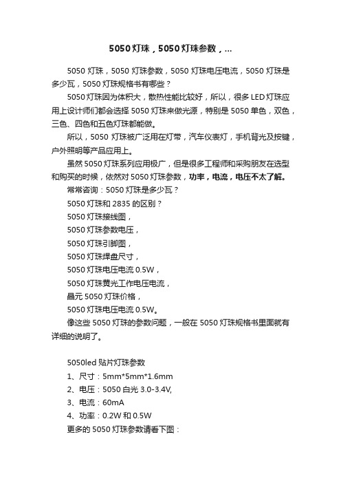
5050led贴片灯珠参数1、尺寸:5mm*5mm*1.6mm2、电压:5050白光 3.0-3.4V,3、电流:60mA4、功率:0.2W和0.5W更多的5050灯珠参数请看下图:5050灯珠和3030灯珠有什么区别?1、封装尺寸不同:(1)、5050灯珠封装尺寸是长、宽、高为 5.0X5.0X1.6mm。
(2)、3030灯珠封装尺寸是长、宽、高为 3.0X3.0X0.6mm。
2、颜色不同:(1)、3030灯珠一般主要是做单色灯为主。
(特别以白光1W为主)(2)、5050灯珠常做成双、三色全彩,一灯双色、三色用混合效果好。
3、功率不同:(1)、3030灯珠功率为0.2-1W。
(2)、5050灯珠功率为常规是0.2W-0.5W。
以上是5050灯珠,5050灯珠参数,5050灯珠电压电流,5050灯珠是多少瓦,5050灯珠规格书有哪些的常用参数。
5050灯珠,5050灯珠参数,5050灯珠电压电流,5050灯珠是多少瓦,5050灯珠规格书尺寸都是比较多咨询的。
5050系列高压灯带规格书1doc

60
LUX-FLT50SW060C-230-020 White 765 lm
60
LUX-FLT50SW060C-230-050 White 765 lm
60
LUX-FLT50WW060C-230-005
Warm white
665 lm
60
LUX-FLT50WW060C-230-020
Warm white
-5-
-2-
深圳纳科士光电科技有限公司
Shenzhen Luxes Optoelectronics CO,.Ltd
Lux-FLT50XX060C-230-XXX
产品光电参数表:
产品型号
颜色
光通量 LED 数
/M
量/M
LUX-FLT50SW060C-230-005 White 765 lm
3.不要将灯带作连续性的扭曲,多次扭曲易造成内部电源线路疲劳损伤,扭 曲角度不小于 45 度,不要在直径 60mm 以下的弧度弯曲。软灯带在户外、 户内使用应做好安全防范措施,以免减少火灾,电击和人身伤害。
4. 在安装时用螺丝将轨道固定在要装饰的物体表面上,将灯嵌入轨道夹内, 注意灯体的发光面部分要朝上。软灯带在使用过程中,请勿用任何物体包 住,遮盖软灯带表面。
使用注意事项
1.每条灯带均接有整流桥堆和插头,只需将插头插入电源插座内即可方便使 用。使用前请明确产品功率,确保供电线路不超负荷,电路有电路保护 器,如电源插座带有保险丝或接了漏电开关。使用时请参照产品技术及光 电参数内容,确保在电压参数±5%范围内工作。
2.如需自定义长度,应在单元组焊接位置剪切,不可小于最小单元长度或在 单元组内剪切。剪切后须注意,切口应用防水绝缘胶封好,以免烧坏产品 或出现安全事故(因此造成的损失,产品供应商不负责)。我司不建议客 人自行裁剪长度,如需求非标准长度产品,请与我司市场人员联系。
5050灯珠规格书

0.4386
4000K
Rank
CIE-X
0.3760
40C02 0.3859 (3900-4100K) 0.3920
0.3822
5000K
Rank
CIE-X
0.3444
50C02 0.3469 (4700-5000K) 0.3558
0.3539
6500K
Rank
CIE-X
0.3104
CIE-Y 0.424 0.4116 0.4204 0.4329
条件 =60mA
=60mA =60mA =60mA
最小
18 20 22
2.9 3.0 3.1 3.2 3.3 118
62
最大
20 22 24
3.0 3.1 3.2 3.3 3.4 123
85
单位 lm V deg -
4
4.: 03/01/2013: 03/01/2013 Rev: 01
5050 灯珠规格书
ZT5050W: 03/01/2013 Rev: 01
目录
1.产品描述 2.最大额定值 3.光电参数 4.典型光电特性曲线 5.分光标准 6.可靠性测试 7.产品规格尺寸 8.料盘结构和包装 9.回流焊 10.使用注要事项
240℃ 20-40 秒 最大 6℃/每秒 最大 8 分钟
10.使用注意事项 储存 (1) 打开包装前 在温度不超过 40℃及湿度不超过 90%RH 条件下,LED 可以保存一年,在储存的时候, 建议采用带干燥剂的防潮袋的包装方式。 (2)打开包装后 LED 需要储存在<=40℃&<=60%RH 相对湿度的条件下,我们强烈建议您从打开包装到 完成贴片整个过程在一个星期内完成。 如果有未使用完的剩余 LED,我们建议重新使用出厂时的防潮剂,并且需要重新密封。 如果干燥剂过期了,请将 LED 放在 60℃烤箱烘烤 12 小时。 LED 电极和引线框架是由表面镀了银的铜合金构成,镀银层会受到来自周围环境的破 坏,请把 LED 远离那种会腐蚀 LED 电极镀银层的环境,LED 电极被腐蚀后,会降低它的 焊接能力和光电参数。 请避免 LED 使用在温度快速变化的环境中,尤其是会发生冷凝的高湿环境中。
智能LED控制和光源电路的5050大小包装产品说明书
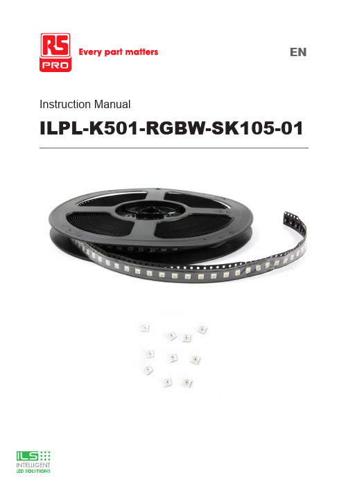
Instruction ManualILPL-K501-RGBW-SK105-01Product OverviewThe ILPL-K501-RGBW-SK105-01 is an Intelligent LED with control and light emitting circuit, all contained in a 5050 sized package.Based on the industry standard SK6182 device, the control circuit consists of signal shaping amplification, built-in constant current source, and a high precision RC oscillator.The data protocol being used is the unipolar NRZ communication mode, where the 32-bit data is transmitted from the controller to DIN of the first LED, after an internal data latch, the remaining data is passed through the internal amplification circuit and sent out of the DO port to the remaining pixels. Using ‘automatic shaping forwarding technology’ means the number of cascaded LEDs is only limited by the signal transmission speed.Applicationsz Task Lightingz Back Lightingz Desk Lightingz Garage Lightingz Accent Lightingz Under Cabinet Lightingz Bar Lightingz Refrigerationz Industrial Applicationsz PhotographyTechnical Featuresz Control circuit and the RGBW die all in one 5050 sized devicez Grey level adjusting control (256 level grey scale)z Red drive special control enhances colour balancez Transmission distance between two points can be up to 10Mz Using a typical data transmission frequency of 800 Kbps, you can achieve refresh rates of 30 frames per secTechnical Drawing (mm)Notes:1. All dimensions are in millimeters.2. Tolerance is ±0.1mm unless otherwise notedPIN configurationAbsolute Maximum Ratings (Ta=25˚,VSS=0V)The electrical parameters (unless otherwise specified, TA=-20 - +70˚C, VDD=4.5 - 5.5V, VSS=0V)The dynamic parameters (Ta=25˚C)The data transmission time (TH+TL=1.25μs±600ns)T0H0 code, high level time0.3μs±0.15μs T0L0 code, low level time0.9μs±0.15μs T1H 1 code, high level time0.6μs±0.15μs T1L 1 code, low level time0.6μs±0.15μs Trst Reset code, low level time80μsTiming waveformmode:ConnectionInputcode:The method of data transmissionThe data structure of 24bitNote: high starting, in order to send data (R7 - R6 - ...... ..W0) The typical application circuit:CIE chromaticity coordinates (ANSI Natural white)ANSI Warm White Color bin structuresStandard LED Performance Graph1020%0.0040%60%80%Forward Current(mA)Forward Voltage(V) Tj=25 °CN o r m a l i z e d L u m i n o u s F l u xF o r w a r dC u r r e n t (m A )Typical Relative Luminous Flux vs. Forward CurrentForward Voltage vs. Forward Current12040608010020%0.0040%60%80%Thermal Pad Temperature (T=25°C)N o r m a l i z e dL u m i n o u s F l u xThermal Pad Temperature vs. Relative Light Output12020%0.0040%60%80%Wavelength (nm)R e l a t i v e E m i s s i o n D i s t r i b u t i o nWavelength Characteristics7590604530150.40.20.60.81.090°Typical Radiation Pattern 120°Radiation Angle1020150150.02050150150%200406080100F o r w a r d C u r r e n t (m A )Thermal Pad Temperature vs. Forward Current200406080100Thermal Pad Temperature (°C)120TOP SMD LED Application Notes1. FeaturesThe Purposes of making OPSCO’s customers and users to have a clear understanding on the ways how to use the LED.2. DescriptionGenerally. The LED can be used the same way as other general purposed semiconductors. When using OPSCO’s TOP SMD LED, the following precautions must be taken to protect the LED.3. Cautions3.1. Dust & CleaningThis emitter has a silicone surface, There are many benefits to the silicone surface in terms of optical properties and improved reliability. However, silicone is a softer material and prone to attract dust. Whilea minimal amount of dust and debris on the LED will not cause significant reduction in illumination, steps should be taken to keep the emitter free of dust.These include keeping the LEDs in the manufacturer’s package prior to assembly and storing assemblies in an enclosed area after installing the emitters.Surface condition of this device may change when organic solvents such as trichloroethylene or acetone were applied.Avoid using organic solvent, it is recommended that isopropyl be used as a solvent for cleaning the LEDs. When using other solvents, it should be confirmed beforehand whether the solvents will dissolve the package and the resin of not.Do not clean the LEDs by the ultrasonic. When it is absolutely necessary, the influence as ultrasonic cleaning on the LEDs depends on factors such as ultrasonic power. Baking time and assembled condition. Before cleaning, a pre-test should be done to confirm whether any damage to the LEDs will occur.3.2. Moisture Proof PackageIn order to avoid the absorption of moisture during transportation and storage, LED are packed in the aluminum envelop, A desiccant is included in the aluminum envelop as it absorbs moisture. When moisture is absorbed into the AMT package it may vaporize and expand during soldering. There is a possibility that this can cause exfoliation of the contacts and damage to the optical characteristics of the LEDs. For this reason, the moisture proof package is used to keep moisture to a minimum in the package.3.3. StorageIn order to avoid the absorption of moisture, It is recommended to store SMD LED (in bulk or taped) inthe dry box (or the desiccator ) with a desiccant, Otherwise to store them in the following environment as recommended.a. Temperature: 5˚C — 30˚Cb. Humidity: 60% RH MaxIt is recommended to solder the LED as soon as possible after unpacking the aluminum envelop, But in case that the LED have to be left unused after unpacking envelop again is requested.The LED should be soldering within 1 hours after opening the package.If baking is required, A baking treatment should be performed as follows:70˚C ±5˚C for more than 24 hours.Reflow Soldering CharacteristicsIn testing, OPSCO has found S50 LEDs to be compatible with JEDEC J-STD-020C,using the parameters listed below. As a general guideline OPSCO recommends that users follow the recommended soldering profile provided by the manufacturer of solder paste used.Note that this general guideline is offered as a starting point and may require adjustment for certain PCB designs and Configurations of reflow soldering equipment.Tem per at ure(°C )L Profile Feature Lead-Based Solder Lead-Free SolderAverage Ramp-Up Rate (Ts max to Tp )3˚C/second max.3˚C/second max.Preheat: Temperature Min (Ts min)100˚C 150˚CPreheat: Temperature Min (Ts max)150˚C 200˚CPreheat: Time ( ts min to ts max )60-120 seconds 60-180 secondsTime Maintained Above: Temperature (TL)183˚C 217˚CTime Maintained Above: Time (t L)60-150 seconds 60-150 secondsPeak/Classification Temperature (T P)215˚C 240˚CTime Within 5˚C of Actual Peak Temperature ( tp)<10 seconds <10 secondsRamp-Down Rate 6˚C/second max.6˚C/second max.Time 25˚C to Peak Temperature <6 minutes max.<6 minutes max.Note: All temperatures refer to topside of the package, measured on the package body surface.Heat GenerationThermal design of the end product is of paramount importance. Please consider the heat generation of the LED when making the system design. The coefficient of temperature increase per input electric power is affected by the thermal resistance of the circuit board and density of LED placement on the board, as wellas components. It is necessary to avoid in tense heat generation and operate within the maximum rating given in this specification. The operating current should be decided after considering the ambient maximum temperature of LEDs.Electrostatic Discharge & Surge CurrentElectrostatic discharge (ESD) or surge current (EOS) may damage LED.Precautions such as ESD wrist strap, ESD shoe strap or antistatic gloves must be worn whenever handling of LED.All devices, equipment and machinery must be properly grounded.It is recommended to perform electrical test to screen out ESD failures at final inspection.It is important to eliminate the possibility of surge current during circuitry design.Moisture Proof PackageCannot take any responsibility for any trouble that are caused by using the LEDs at conditions exceeding our specifications.The LED light output is strong enough to injure human eyes. Precautions must be taken to prevent looking directly at the LEDs with unaided eyes for more than a few seconds.The formal specification must be exchanged and signed by both parties before large volume purchase begins. The appearance and specifications of the product may be modified for improvement without notice.For further information please contact ILSThe values contained in this data sheet can change due to technical innovations. Any such changes will be made without separate notification.。
TM1914A_V1

采用功率CMOS工艺 OUT输出端口耐压24V VDD内置5V稳压管,串接电阻后电压支持6~24V 固定恒流输出18mA PWM辉度控制电路,256级辉度可调 精确的电流输出值
(通道与通道)最大误差:±3%
(芯片与芯片)最大误差:±5% 单线双通道串行级联接口:芯片数据接口可通过命令配置DIN或FDIN脚输入,正常模式下输入
VCC VCC
Di 100R
控制器 Fi 100R
GND
OUTR OUTG OUTB
DIN
TM1914A DO
FDIN IC1
SET GND VDD
100R 100R
OUTR OUTG OUTB
DIN
TM1914A DO
FDIN IC2
SET GND VDD
100R 100R
OUTR OUTG OUTB
1
8
2 Top View 7
3
6
4
5
VDD FDIN GND DIN
管脚功能
引脚名称
DIN FDIN DO OUTR OUTG OUTB VDD GND
输入输出等效电路
图2
引脚序号
I/O
5
I
7
I
4
O
1
O
2
O
3
O
8
--
6
--
功能说明
数据输入 备用数据输入
数据输出 N管开漏,恒流输出 N管开漏,恒流输出 N管开漏,恒流输出
©Titan Micro Electronics
V1.0
5
5、数据接收和转发
3 通道 LED 恒流驱动专用电路 TM1914A
5050RGBLED灯珠全彩规格书88
Max.260℃ for 5 sec Max. (3min from the base of the epoxy bulb)
■Typical Electrical & Optical Characteristics(Ta=25°)
Items Symbol Condition
G,B
Min 3.0 1.9 --620 518 465 700 1800 400 ---
5℃,IF=30mA
Test Item Operating Life Test High Temperature Storage Low Temperature Storage Temp &Humidity Test
Duration 1000h
Units Tested 22
Number of Damaged 0/22
25℃~85 ℃~25℃ 3min -5min30min- 5min
50 Cycles
22
0/22
Mechanical Test
Resistance to Soldering Heat Lead Integrity
260±5℃,
10±1sec
1 time
22
0/22
Load 2.5N 0°~90°~0°
DONGGUAN TONGJIA OPTOELECTRONICS TECHNOLOGY CO., LTD
Typical Electrical/Optical Characteristics Curves (G):
Customer Service Hotline:400-676-8616
TEL:0769-8200 5999 0769-8200 2226 FAX:0769-8200 2777 E-MIAL∶tongjiacn@
LED 5050硬灯条规格书
确认后请回传,谢谢!Please confirm and fax to us ,thank you!XL-5050 LED 硬灯条产品效果展示:LED 硬灯条 5050灯珠效果 LED 硬灯条 5050灯珠效果一、 特点:1、采用高亮度SMD5050 LED 灯珠 , 铝合金外壳 , 每三个LED 为一段。
2、每条的标准长度为1M ,每条灯珠数量分别有 30PCS/M LED 灯珠 ,60PCS/M LED 灯珠 ,72PCS/M LED 灯珠3、发光颜色:红/绿/蓝/黄/白/暖白和长彩等多种颜色可供选择4、工作电压:DC12V/DC24V 两种5、防水型SMD 灯条,表面采用灌胶二、 用途:1、SMD 高亮度硬灯条适用于酒店,超薄灯箱,KTV 娱乐场所等室内装饰。
2、用于广告招牌等精品装饰领域。
3、度假装饰照明灯,显示及展览。
4、商场专柜,珠宝,首饰台及名贵钟表柜台。
三、产品规格:四、参数灯珠类型号: SMD 5050 LED 可选颜色: 红/绿/蓝/黄/白/暖白/RGB发光角度: 120度 灯珠数量: 30PCS / M 60PCS / M 72PCS / M 外形尺寸: 1000*10*2mm 按整体封存装: 裸板 V 型槽 U 型槽硬灯条套V 型槽图示硬灯条裸板图示U 型槽图示五、 注意事项:六、产品应用应用家居装饰应用KTV 装饰珠宝柜装饰●使用说明use manual:1.请先仔细阅读产品规格书,确认其使用环境是否符合规格书上的条件上,方可放心使用. Please read the specificationfirst to make sure the using condition is fit2.将产品接入电源时,请先确保开关处于闭合状态..Please shut off the switch before connect the product, then turn on3.本产品保质期为一年This product warranty for one year4.。
5050RGBW中文规格书
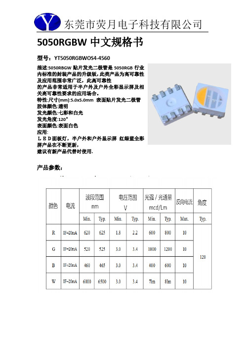
5050RGBW中文规格书型号:YT5050RGBWOS4-4560描述:5050RBGW贴片发光二极管是5050RGB行业内标准的封装产品的升级版,此类产品为高可靠性及应用范围非常广泛,此高可靠性的产品非常适用于半户外及户外全彩显示屏及相关高可靠性要求的应用场合。
特性:尺寸(mm):5.0x5.0mm 表面贴片发光二极管胶体颜色:透明发光颜色:七彩和白光发光角度:120°表面颜色:表面白色应用:LED面板灯,半户外和户外显示屏红绿蓝全彩屏产品在不断更新,建议有新产品代替时使用.产品参数:注意:所有尺寸单位为mm;如无特殊说明误差范围为±0.05mm 。
***应用注意事项特点本文件主要向顾客及用户介绍怎样如何更好的使用我司的SMD LED 产品。
描述一般来说,SMD 5050跟一般的半导体有相同的用法。
当使用荧月电子的SMD5050产品,请遵从以下的使用方法以保护SMD LED 产品。
1.清洁:不要使用不明化学液体清洗SMD LED,不明的化学液体可能会损坏SMDLED。
当必要清洗时,把SMD LED沉浸在酒精里,在正常的室温下少于1 分钟并且自然干燥15 分钟,然后才开始使用。
2.防潮湿包装为避免产品在运输及储存中吸湿,SMD LED 的包装是用防潮的铝包装袋包装,并且包装袋里面含有干燥剂及湿度卡,干燥剂主要起到控制包装袋里的湿度,湿度卡主要是起到监控包装袋里的湿度。
3.储存a.包装袋密封后贮存在条件为温度< 40℃,湿度< 60%RH,保存期为12 个月。
当超过保质期时,需要重新烘烤。
b.在开包装之前,请先检查包装袋有无漏气或湿度指示卡有无变色,如果有漏气或湿度指示卡有变色现象,请重新烘烤后再使用。
c.开封后请在以下条件使用:温度< 30℃、湿度在30%RH 以下;如果使用时间超出24小时,须做以下烘烤处理才可使用。
d.烘烤条件:产品在烘箱在温度为70℃±5℃;相对湿度≤10%RH,时间:24 小时。
- 1、下载文档前请自行甄别文档内容的完整性,平台不提供额外的编辑、内容补充、找答案等附加服务。
- 2、"仅部分预览"的文档,不可在线预览部分如存在完整性等问题,可反馈申请退款(可完整预览的文档不适用该条件!)。
- 3、如文档侵犯您的权益,请联系客服反馈,我们会尽快为您处理(人工客服工作时间:9:00-18:30)。
TM1914D
功能特点
◆TM1914D把IC驱动晶片与RGB芯片集成在一个8脚5050封装中,构成一个完整的像素点
◆驱动IC晶片采用串行归一码的通讯方式
◆驱动IC内置5V稳压管,串接电阻电压支持DC6~24V,在此工作电压下可带普通RGB光源
◆驱动IC固定恒流输出18mA,256级PWM辉度可调
◆内置上电复位电路,上电复位后所有寄存器初始化为零
◆数据传输速率800Kbps,当刷新速度30帧/秒时,级联点数可以不低于1024个像素点, 当
刷新速度15帧/秒时,级联点数可以不低于2048个像素点
◆TM1914D为串行单线双通道传输支持断点续传功能,芯片双通道数字接口(DIN、FDIN)可
互相切换输入,D0脚转发级联的数据,做到信号不因某颗驱动异常而影响其他正常工作,提高产品稳定性。
◆驱动IC内置信号自动整形电路,对控制器或上一个芯片传来的可能失真的数据信号进行修
正,调整为标准数据波形后再转发给下级,使信号不随级联变远而出现失真或衰减
外形尺寸及引脚图(单位mm)
引脚功能
内置LED灯芯光电参数:
内置驱动芯片电气及开关特性
时序特性(T0/T1周期= 1.25μs±150ns)
DIN
DO
程序调试应用说明
1.完整数据结构
C1C2D1D2D3D4
Dn
…
C1C2D1D2D3D4
Dn
…Reset
Reset
C1、C2为模式设置命令,各包含24bit 数据位,每个芯片都会接收并转发C1、C2,其中C1为命令码,C2为检验反码。
D1、D2、D3、D4、……、Dn 为各芯片的PWM 设置命令,数据格式相同,D1表示级联第1颗芯片的显示数据包,Dn 表示级联第n 颗芯片的显示数据包,每个显示数据包包含24bit 数据位。
Reset 表示复位信号,高电平有效。
2.工作模式设置
TM1914D 内置的芯片采用串行归一码的通讯方式。
芯片接收显示数据前需要配置正确的工作模式,选择接收显示数据。
芯片复位开始接收C1C2数据,模式设置命令共有3种:
(1)0xFFFFFF_000000命令为正常工作模式:
在此模式下,首次默认DIN 接收显示数据,芯片检测到该端口有信号输入则一直保持该端口接收,如果超过300ms 未接收到数据,则切换到FDIN 接收显示数据,芯片检测到该端口有信号输入则一直保持该端口接收,如果超过300ms 未接收到数据,则再次切换到DIN 接收显示数据。
DIN 和FDIN 依此循环切换,接收显示数据。
(2)0xFFFFFA_000005命令为DIN 工作模式:
在此模式下,芯片只接收DIN 端输入的显示数据,FDIN 端数据无效。
(3)0xFFFFF5_00000A 命令为FDIN 工作模式:
在此模式下,芯片只接收FDIN 端输入的显示数据,DIN 端数据无效。
3、显示数据Dn 的数据格式
每个显示数据包包含8×3bit 数据位,高位先发。
G[7:0]:用于设置OUTR 输出的PWM 占空比。
全0码为关断,全1码为占空比最大,256级可调。
R[7:0]:用于设置OUTG 输出的PWM 占空比。
全0码为关断,全1码为占空比最大,256级可调。
B[7:0]:用于设置OUTB 输出的PWM 占空比。
全0码为关断,全1码为占空比最大,256级可调。
5、数据接收和转发
其中S1为控制器Di 端口发送的数据,S2、S3、S4为级联芯片转发的数据。
控制器Di 和Fi2端口数据结构:C1C2D1D2D3D4……Dn ; 控制器Fi 端口数据结构:C1C2DxD1D2D3……Dn ; 其中,Dx 为任意24bit 数据位。
芯片级联和数据传输并转发过程如下:控制器发送数据S1,芯片1接收C1和C2进行校验,如
果命令正确,则转发C1和C2,同时吸收D1,如果此时没有Reset复位信号,芯片1将一直转发控
制器继续发来的数据;芯片2也接收C1和C2进行校验,如果命令正确,则转发C1和C2,同时吸
收D2,如果此时没有Reset复位信号,芯片2将一直转发芯片1继续发来的数据。
依此类推,直到
控制器发送Reset复位信号,所有芯片将会复位并把各自接收到的24bit显示数据解码后控制OUT
端口输出,完成一个数据刷新周期,芯片又回到接收准备状态。
Reset高电平有效,保持高电平时
间大于200μs,芯片复位。
芯片采用自动整形转发技术,信号不会失真衰减,使得该芯片的级联个数不受信号传送的限制,仅仅受限刷屏速度要求。
并且对于所有级联在一起的芯片,数据传输的周期是一致的。
TM1914D典型应用电路
常规开关电源还有DC24V,当为24V供电时可以做到带5颗或6颗普通,原理图可参考DC12V 应用,只是通道电阻需要相应变更合适阻值即可。
为防止产品在测试时带电插拔产生的瞬间高压导致芯片信号输入输出引脚损坏,应该在信号输入及输出脚串接100Ω保护电阻。
此外,图中各芯片的104退耦电容不可缺少,且走线到芯片的VDD 和GND脚应尽量短,以达到最佳的退耦效果,稳定芯片工作。
其他注意事项:
1.对于TM1914D可以配置为DC5V-24V供电,但根据输入电压不同,应配置不同的电源电阻,电阻计算方法:VDD端口电流按10mA计算,VDD串接电阻R=(DC-5.5V)÷10mA(DC为电源电压)。
2.对于TM1914D在使用DC5V-24V带普通光源时需对每通道配置电阻,是因为灯珠内置驱动芯片为恒流驱动,只需当OUT端口电压达到0.8V就会进入恒流状态。
但并非电压越高越好,电压越高,芯片的功耗就越大,加之RGB灯芯本身发热,会使灯珠温度更高,温度过高时会降低整个系统的可靠性。
故建议OUT端口开通电压在1.0~1.5V之间较为合适,在接高压(6-24V)时可以通过串接电阻的方式来降低OUT端口过高的电压。
以下是选用电阻阻值的计算方式:
系统驱动电压:DC 单个LED导通压降:Vled
串联LED个数:n 恒流值:Iout
电阻:R TM1914D恒流电压:4.5V(灯珠3V,驱动IC 1.5V)
R=(DC-1.5V -Vled×n)÷ Iout
例:系统供电:DC24V,单个LED导通压降:3V,串联LED个数:6,恒流值:18mA,根据上述公式计算可得:R=(24V-4.5V-5×3.2V)÷18 mA≈200Ω,只需在OUT端口串联200Ω左右的电阻即可。
