电机驱动IC UCC3626手册
英飞凌tricore用户手册 第24章 捕捉比较单元CCU6
捕获/比较单元 6(CCU6)
表24-1
CCU6 模块寄存器 (接上表)
寄存器缩略名 寄存器完整名 地址偏 访问类型 复位值
移量 读写
IS
中断状
A0H U, SV U,SV 0000 0000H
态寄存
器
ISS
中 断 状 态 A4H U, SV U, SV 0000 0000H
置位寄存
器
ISR
中断状态复 A8H U, SV U, SV 0000 0000H
CMPSTAT CMPMODIF T12MSEL TCTR0 TCTR2 TCTR4
调制控制寄 存器
MODCTR TRPCTR PSLR MCMCTR MCMOUTS MCMOUT
IS ISS ISR INP IEN
ID寄存器
ID
LI IMON KSCFG KSCSR MCFG PISEL 2 PISEL 0
用户手册 CCU6, V0.3
24-4
V1.0, 2011-12
TC1728
捕获/比较单元 6(CCU6)
注: 内核寄存器的绝对地址由寄存器相对地址(在表24-1中给出)加上内核基地址 (在表24-14中给出)得到。
表24-1
CCU6 模块寄存器
寄存器缩略名 寄存器完整名 地址偏 访问类型
移量 读写
定时器13 块功能 • 有一个输出的独立比较通道 • 16位分辨率,最大计数频率=外设时钟 • 并发更新T13寄存器 • 可以同步到T12 • 在周期匹配和比较匹配产生中断 • 支持单触发模式 • 可用外部事件控制启动 • 有计数外部事件的能力
附加的特殊功能
• 为无刷DC驱动实现块整流 • 通过霍尔传感器模型进行位置检测 • 噪声过滤器支持的位置输入信号 • 为块整流提供的自动旋转速度测量和整流控制 • 综合集成性错误处理 • 通过外部信号(CTRAP)而不需要 CPU载入的快速急停 • 多通道AC驱动的控制模式 • 可选择输出电平并使其与上电步伐相适应
CDE360系列矢量变频器使用手册V2.0

CDE360系列矢量变频器使用手册V2.0•前言•简介•入门操作指导•第一章安全注意事项o 1.1 安全事项o 1.2 注意事项•第二章产品信息o 2.1 CDE360技术规范o 2.2 CDE360命名规则o 2.3 CDE360铭牌标贴o 2.4 CDE360型号与技术参数▪ 2.4.1 CDE360通用系列▪ 2.4.2 CDE362系列▪ 2.4.3 CDE365系列▪ 2.4.4 CDE366系列▪ 2.4.5 CDE505 IP54系列o 2.5 CDE360外观及尺寸▪ 2.5.1 CDE360通用系列▪ 2.5.2 CDE505 IP54系列o 2.6 CDE360键盘外型尺寸▪ 2.6.1 键盘A(LED)▪ 2.6.2 键盘A底座▪ 2.6.3 键盘B(LED和LED+LCD双显)▪ 2.6.4 键盘B底座▪ 2.6.5 键盘D(IP54)▪ 2.6.6 防尘板A▪ 2.6.7 防尘板Bo 2.7 变频器选型建议o 2.8 制动电阻、制动单元选型推荐•第三章安装o 3.1 机械安装▪ 3.1.1 安装现场▪ 3.1.2 安装方向和空间▪ 3.1.3 键盘及面盖拆卸与安装o 3.2 电气安装▪ 3.2.1 外围电气元件使用说明▪ 3.2.2 外围电气元件选型指导▪ 3.2.3 变频器端子接线示意图▪ 3.2.4 主回路功率端子说明▪ 3.2.5 控制端子及接线说明•第四章操作显示与应用说明o 4.1 键盘操作和显示▪ 4.1.1 键盘外观▪ 4.1.2 键盘指示灯▪ 4.1.3 键盘按键功能▪ 4.1.4 键盘LED显示▪ 4.1.5 数值转换o 4.2 菜单介绍o 4.3 参数设置o 4.4 状态监控o 4.5 启停控制▪ 4.5.1 启停命令来源▪ 4.5.2 启动方式▪ 4.5.3 停机方式▪ 4.5.4 定时停机▪ 4.5.5 点动运行o 4.6 频率给定▪ 4.6.1 主频率源A▪ 4.6.2 辅频率源B▪ 4.6.3 主、辅频率源关系o 4.7 电机运行方向设置o 4.8 电机参数及自整定▪ 4.8.1 两套电机参数切换▪ 4.8.2 电机参数自整定操作o 4.9 带PG卡的使用方法o 4.10 用户密码o 4.11 参数上传下载o 4.12 常用菜单显示模式•第五章功能参数简表o A0 监控(只读类参数)o A1 故障与诊断(只读类参数)o b0 基本参数o b1 运行停止o b2 频率源o C0 开关量输入o C1 开关量输出o C2 模拟输入o C3 模拟输出o C4 脉冲输入输出o C5 虚拟开关量输入输出o d0 电机控制o d1 电机参数o d2 速度控制o d3 转矩控制o d5 电机2参数o d6 电机2速度控制o E0 点动o E1 跳频o E2 多段速o E3 简易PLCo E4 加减速时间o E5 PIDo E6 多泵控制o E7 摆频及定长计数o E8 下垂控制o E9 瞬停不停o EA 抱闸控制o Eb 限幅监控o F0 保护o F1 自动复位o H0 系统参数o H1 模拟量校正o L0 通讯设置o L1 主从控制o L2 编码器设置o P0 自定义参数o P1 调试参数o P2 厂家参数•第六章参数说明o A0组监控(只读类参数)o A1组故障与诊断(只读类参数)o b0组基本参数o b1组运行停止o b2组频率源o C0组开关量输入o C1组开关量输出o C2组模拟输入o C3组模拟输出o C4组脉冲输入输出o C5组虚拟开关量输入输出o d0组电机控制o d1组电机参数o d2组速度控制o d3组转矩控制o d5组电机2参数o d6组电机2速度控制o E0组点动o E1组跳频o E2组多段速o E3组简易PLCo E4组加减速时间o E5组 PIDo E6组多泵控制o E7组摆频及定长计数o E8组下垂控制o E9组瞬停不停o EA组抱闸控制o Eb组限幅监控o F0组保护o F1组自动复位o H0组系统参数o H1组模拟量校正o L0组通讯设置o L1组主从控制o L2组编码器设置o P0组自定义参数o P1组调试参数•第七章故障告警检测与排除o7.1 故障告警信息与排除方法o7.2 常见故障及其处理方法•第八章MODBUS通讯协议o8.1 协议内容o8.2 组网方式o8.3 总线结构o8.4 协议格式o8.5 协议功能及通讯地址•第九章保养与维护o9.1 日常保养与维护o9.2 易损零部件的检查与更换o9.3 变频器的存储及保修•第十章扩展卡o10.1 IO1(继电器扩展卡)o10.2 IO2(多功能IO扩展卡)o10.3 IO3(多功能IO扩展卡)o10.4 IO4(电机温度采集卡)o10.5 PG1(差分式编码器卡)o10.6 PG2(OC式编码器卡)•附录:版本变更记录CDE360 矢量变频器使用手册前言前言感谢您选用深圳市康元电气技术有限公司制造的CDE360 系列变频器!CDE360 系列变频器是一款针对通用场合研发的高性能矢量控制变频器,既适用于一般性的风机、水泵类负载驱动,也可广泛用于纺织、锯石、空压、油田等行业自动化设备控制,还可以为球磨、注塑、智能电机等专业应用提供一体化解决方案。
磁保持继电器驱动芯片 HZ3606 数据手册说明书

磁保持继电器驱动芯片特点⏹5V~36V 输入电压范围⏹低静态工作电流⏹输入高低转换电平为2.2V ⏹400mA 典型驱动电流管脚图(SOT23-6)123456OAVIN B 应用场合⏹磁保持继电器驱动管脚解释序号名称功能1OB 输出端B 2GND 地3A 输入端A 4OA 输出端A 5VIN 芯片供电电源6B输入端B极限参数VIN ,A ,B 电压............................................................................................................................................-0.3V~40V 存储温度..............................................................................................................................................-55°C to +150°C推荐工作条件VIN 电压..............................................................................................................................................................5V~30V A ,B 电压...........................................................................................................................................................0V~30V 工作温度..............................................................................................................................................-40°C to +105°C芯片框图电气参数表(除非特别说明,测试条件为V 符号参数测试条件最小值典型值最大值单位供电VIN V IN 输入电压范围536V I Q1静态工作电流1V IN =12V,A=B=0V 1μA I Q2静态工作电流2V IN =12V,A=5V,B=0V,OA 和OB 悬空500μAI Q3静态工作电流3V IN =12V,A=5V,B=5V ,OA 和OB 悬空100μAMOSFET 参数R DS_ON_H PMOS(上管)导通电阻7ΩR DS_ON_L NMOS(下管)导通电阻3ΩV TH输入高电平门限电压-40°C ~105°C1.62.22.7V续流二极管参数V SD_P 续流二极管正向导通压降1.5V V SD_N 续流二极管正向导通压降1V T RR 反向恢复时间200nS传输特性T R 上升沿时间R L =48Ω100nS T D(on)开通延时R L =48Ω100nST F下降沿时间R L=48Ω100nS T D(off)关断延时R L=48Ω100nS 输入下拉电阻R A输入端A下拉电阻100kΩR B输入端B下拉电阻100kΩ描述HZ3606是双向继电器驱动集成电路,用于驱动控制直流电机、磁保持继电器等,具有输出电流大,静态功耗小的特点,可广泛用于智能电表、无功补偿控制器及其他需要脉冲控制的应用场合。
两相步进电机驱劢器使用说明DM3622DM362信浓步进电机

两相步进电机驱动器使用说明一.产品简介1.概述新推出的数字式两相步进电机驱动器,采用PI 控制算法,低噪音,低振动,低发热,低中高速运行都很平稳,性能优越,适合驱动中小型的任何2.2A 相电流以下的两相或四相混合式步进电机。
可通过拨码开关选择运行电流和细分,有 16 种细分,16 种电流供选择,具有过压、欠压报警,相电流过流保护,马达相位开路检测,其输入控制信号均采用光电隔离。
内置自运行模式,可以通过跳线设置受控自运行及持续自运行模式,有SW5-SW8设置自运行速度,也可由外部信号控制自运行时的启动和停止以及电机的正反转。
脉冲,方向,和使能端都有恒流和反向保护,可以直接接 4-28V 的信号电平。
驱动器内置自动半流,极大地减小了电机发热。
2.特性PI 控制算法,低噪音,低振动,低发热; 信号输入:单端,脉冲+方向及双脉冲; 内置微细分;供电:最大可达DC36V ;电流设定方便,16档可选,输出电流峰值可达 2.2A ; 静止 1S 后电流减半可驱动 4,6,8线两相步进电机,对不同电机具有参数自动整定功能; 出厂默认最高细分128,16档可调,可根据客户要求定制; 光隔离差分信号输入,输入脉冲频率最大300KHz ;具有过压、欠压报警,相电流过流保护,马达相位开路检测等功能;脉冲,方向和使能端子都有恒流输入功能,可以直接连接输入信号,而不用外加串联电阻降压限流保护。
高可靠性:采用多层板和表面贴封,功率器件留有足够余量;3. 应用领域适合各种中小型自动化设备和仪器,例如:气标机、打标机、贴标机、割字机、镭射打标机、绘图仪、数控机床、小型雕刻机、自动装配设备等。
在用户期望小噪声、高精度、高速度的设备中应用效果特佳。
二.性能指标DM3622DM3622是深圳市维科特机电有限公司三.端口与接线1.端口描述1)控制信号接口名称PUL+(CCW+) 脉冲输入信号:脉冲有效沿可调,默认脉冲上升沿有效;为了可靠响应脉冲信号,脉冲宽度应大于双脉冲模式下:CCWPUL-(CCW-)DIR+(CW+) 方向输入信号:高/低电平信号,为保证电机可靠换向,方向信号应先于脉冲信号至少线有关,互换任一相绕组(如DIR-(CW-)2.控制信号连接驱动器采用差分式接口电路可适用差分信号,单端共阴及共阳等接口,内置高速光电耦合器,允许接收长线驱动器,集电极开路和PNP 输出电路的信号。
NI 9476数据表 36V、32通道源极输出数字模块说明书

数据表NI 9476数据表36 V、32通道(源极输出)、500 µsC系列数字模块•每通道250 mA最大电流驱动(所有通道)•DSUB或弹簧端子连接•250 V RMS, CAT II,通道对地隔离(弹簧端子);60 V DC, CAT I,通道对地隔离(DSUB)注:本文档中,NI 9476(弹簧端子接口)和NI 9476(DSUB接口)统称为NI 9476。
NI 9476用于测量工业逻辑电平和信号,可直接连接至多种工业开关、换能器和设备。
每个通道都可接受6 V~36 V的信号(信号电平取决于外部电源),并具有输出通道和背板间的瞬间过压保护。
可通过程序监控每条通道的内置过流和短路保护状态。
套件内容所需附件• NI 9476• NI 9476入门指南• NI 9923前面板安装DSUB至螺栓端子(DSUB)或• DIN导轨37针,弹簧端子连接器接线盒,带屏蔽式母头至公头线缆,1米(DSUB)• NI 9940后壳套件(弹簧端子)NI C 系列概述NI 提供超过100种C 系列模块,用于测量、控制以及通信应用程序。
C 系列模块可连接任意传感器或总线,并允许进行高精度测量,以满足高级数据采集及控制应用程序的需求。
•与测量相关的信号调理,可连接一组传感器和信号•隔离选项包括组间、通道间以及通道对地•温度范围为-40 °C ~70 °C ,满足各种应用程序和环境需要•热插拔CompactRIO 和CompactDAQ 平台同时支持大部分C 系列模块,用户无需修改就可将模块在两个平台间转换。
2 | | NI 9476数据表CompactRIOCompactRIO 将开放式、小型化和坚固耐用的嵌入式架构与C系列模块集成在一个平台上。
平台基于 NILabVIEW RIO架构。
每个系统包含一个FPGA,用于自定义定时、触发以及处理一系列可用的模块化I/O,可满足任何嵌入式应用程序的需求。
CS5460A中文数据手册

单相双向功率/电能 IC
特性
l l l l l l l l l l l l l l l 电能数据线性度:在1000 :1 动态范围内线性度 为 ±0.1% 片内功能:可以测量电能(有功),I *V,IRMS 和 VRMS ,具有电能-脉冲转换功能 可以从串行EEPROM 智能“自引导”,不需要微 控制器 AC 或DC 系统校准 具有机械计度器/步进电机驱动器 符合IEC687/1036 ,JIS 工业标准 功耗<12mW 优化的分流器接口 V对I的相位补偿 单电源地参考信号 片内2.5V 参考电压(最大温漂60ppm/℃) 简单的三线数字串行接口 看门狗定时器 内带电源监视器 电源配置 VA+ = +5 V; VA- = 0V; VD+ = +3.3V~+5 V
1
CS5460A
目
录
1.特性与规格说明 ..................................................................................................................................... 4 模拟特性 .............................................................................................................................................. 5 模拟特性(续) ...................................................................................................
工学学士学位论文

工学学士学位论文单功率光伏水泵驱动器专业名称电气工程及其自动化学生姓名齐琳指导老师蒋伟扬州大学2010年5月摘要水资源和电力资源是制约发展中国家农村和偏远干旱地区发展的重要因素,而这些地区往往拥有丰富的太阳能资源,因此,发展光伏技术并将其用于水泵系统,合理地开发地下水资源,将给这些地区带来巨大生态和经济效益。
本文在现有研究成果基础上,设计了一种基于永磁无刷直流电机的光伏水泵控制系统驱动器。
该设计选用一片无刷直流电机控制器UCC3626,三片IR2110驱动芯片和三相MOSFET逆变电路构成其控制驱动电路。
并利用开关变换电路对阻抗的变换原理,使得负载的等效阻抗跟随太阳能电池的输出阻抗,使得太阳能电池与负载基本匹配,太阳能电池即工作在最大功率点处,实现最大功率点跟踪。
对样机实验测试,控制器能够实现无刷直流电机的准确换相,电机起动平稳,带动水泵正常运行。
最后通过实验研究,总结光伏水泵调速等相关问题,并对未来工作进行了展望关键词:光伏水泵、无刷直流电机、逆变电路、最大功率点跟踪AbstractWater and electricity are important factors which dominate the development of rural and remote dry regions in developing countries. Statistically, there are abundant solar energy resources available in those regions. Therefore, developing solar based technologies, such as solar powered pumping systems to exploit groundwater, will bring enormous ecological and economical benefits to these regions.In this paper, based on the existing research results, design a kind of photovoltaic pump control system drives which based on permanent brushless dc motor .This design chooses a brushless dc motor controller, UCC3626 , three pieces of IR2110 drive chips and three-phase MOSFET inverter circuits constitute its control drive circuit. And by using switch to impedance transformation of commutation circuit principle, make the equivalent impedance load with solar cells, making the output impedance load of solar cells and basic matching, solar cells in the maximum power point that work in realizing the maximum power point tracking.The sample test, the controller can achieve brushless dc motor accurate commutation, motor starting smoothly, drive the pumps normal operation.The experimental research, summarizes problems related to solar pumps speed for future work, and prospectedKeywords:solar water , sensorless BLDC, Inverter circuits,MPPT目录摘要 (II)Abstract (III)1. 绪论 (1)1.1背景资料 (1)1.2发展现状及前景 (1)1.3光伏水泵模型 (3)2、光伏水泵系统工作原理 (4)2.1光伏水泵基本结构与工作参数 (4)2.2无刷直流电机的工作原理 (5)2.2.1无刷直流电机的结构 (5)2.2.2 无刷直流电机工作原理 (6)2.2.3 无刷直流电机的数学模型 (7)3、光伏水泵系统的解决方案 (8)3.1基于感应电机的光伏水泵设计方案 (8)3.2基于无刷直流电机光伏水泵设计方案 (10)3.3比较结果 (12)4、单级光伏水泵解决方案 (12)4.1 功率MOSFET驱动电路设计 (13)4.1.1 IR2110集成驱动电路 (13)4.1.2功率MOSFET逆变电路 (16)4.2光伏水泵控制电路的设计 (19)4.2.1 UCC3626的基本结构及原理 (19)4.3光伏水泵中永磁无刷直流电机的控制系统设计 (26)4.4 基于单片机的最大功率追踪 (28)4.4.1 MPPT算法流程图 (30)4.5系统整合 (31)5、结果与分析 (33)6、未来工作展望 (38)6.1总结 (38)6.2 今后工作展望 (38)7、致谢 (39)8、参考文献 (40)1. 绪论1.1背景资料能源是人类社会生存和发展的物质基础,但随着能源紧张和保护生态环境等问题的日益突出,大力开拓新能源和可再生能源已经成为全球各国共识。
TPS22961 3.5V,6A,超低负载开关数据手册说明书

VBIASProduct FolderSample &BuyTechnical Documents Tools &SoftwareSupport &CommunityTPS22961ZHCSC50B –FEBRUARY 2014–REVISED SEPTEMBER 2014TPS229613.5V ,6A ,超低电阻负载开关1特性•集成单通道负载开关•VBIAS 电压范围:3V 至5.5V •输入电压范围:0.8V 至3.5V •超低R ON 电阻–V IN =1.05V (V BIAS =5V)时,R ON =4.4m Ω•6A 最大持续开关电流•低静态电流小于1µA (最大值)•低控制输入阈值支持使用1.2V/1.8V/2.5V/3.3V 逻辑器件•受控转换率–V IN =1.05V 时(V BIAS =5V),t R =4.2µs •快速输出放电(QOD)•带有散热垫的小外形尺寸无引线(SON)8端子封装•静电放电(ESD)性能经测试符合JESD 22规范–2kV 人体放电模式(HBM)和1kV 器件充电模型(CDM)2应用范围•Ultrabook™/笔记本电脑•台式机•服务器•机顶盒•电信系统•平板电脑3说明TPS22961是一款小型,超低R ON ,单通道负载开关,此开关具有受控开启功能。
此器件包含一个可在0.8V 至3.5V 输入电压范围内运行的N 通道金属氧化物半导体场效应晶体管(MOSFET),并且支持最大6A 的持续电流。
器件的超低R ON 和高电流处理能力的组合使得此器件非常适合于驱动具有非常严格压降耐受的处理器电源轨。
器件的快速上升时间使得电源轨可以在器件被启用时迅速接通,从而减少配电响应时间。
此开关可由ON 端子单独控制,此端子能够与微控制器或低压离散逻辑电路生成的低压控制信号直接对接。
通过集成一个260Ω下拉电阻器,在开关关闭时实现快速输出放电(QOD),此器件进一步减少总体解决方案尺寸。
IAI电缸 RCP2-SA6C 技术手册
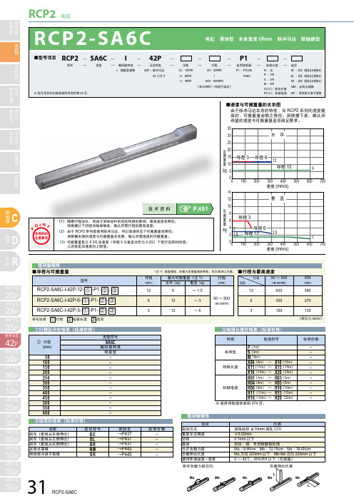
43 58
※ 带刹车型号,全长会增加 40mm(配线从末端 伸出时会增加 53.3mm),重量会增加 0.4kg。
■按行程区分尺寸 • 重量
行程
50 100 150 200 250 300 350 400 450 500 550 600
L A B C D E F H P 重量 (kg)
300 350 400 450 500 550 600 650 700 750 800 850
6
12
~3
50 ~ 500
6
(每 50mm)
3
12
~6
3
300
270
150
135
符号说明 ① 行程 ② 电缆长度 ③ 选项
(单位为 mm/s)
P
①行程区分价格表(标准价格)
① 行程 (mm)
50 100 150 200 250 300 350 400 450 500 550 600
类型符号
SA6C 编码器种类
Ma உડ! ؚ٤নᎳၤə3
Ћ8
16
2.7
ME
SE
(3.1)
19.5 21 19.5
8 23 8 31
˄ਭ૾ৱُ࢞ ±0.02˅!
ᄵ!ڋ
4ˉM5 ແ 9 L
32 ±0.02 50
115
2ˉЋ5H7 ແ 6
119 3 ኊ !ݞME ə2 (2.2)
(240)
ݢେਾဂ ə1
59.5 43 10 6.5 28
500
600
700
型号
导程
(mm)
最大可搬重量(注 1) 水平(kg) 垂直(kg)
行程
(mm)
UC3863的数据手册(LLC)
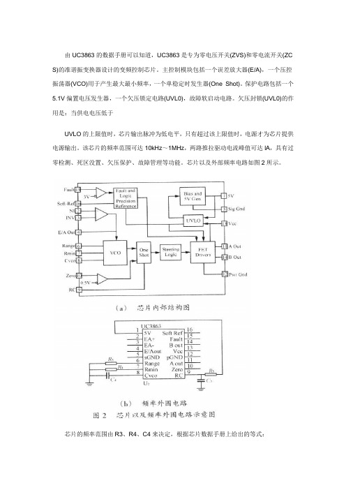
由UC3863的数据手册可以知道,UC3863是专为零电压开关(ZVS)和零电流开关(ZC S)的准谐振变换器设计的变频控制芯片。
主控制模块包括一个误差放大器(E/A),一个压控振荡器(VCO)用于产生最大最小频率,一个单稳定时发生器(One Shot)。
保护电路包括一个5.1V偏置电压发生器,一个欠压锁定电路(UVL0),故障软启动电路。
欠压封锁(UVL0)的作用是:当供电电压低于UVLO的上限值时,芯片输出脉冲为低电平,只有超过该上限值时,电源才为芯片提供电源输出。
该芯片的频率范围可达10kHz~1MHz,两路推拉驱动电流峰值可达lA,具有过零检测、死区没置、欠压保护、故障管理等功能。
芯片以及外部频率电路如图2所示。
芯片的频率范围由R3、R4、C4来决定,根据芯片数据手册上给出的等式:选择R3及R4合适的值就来可以确定芯片实际运行频率范围。
死区由R5、C5来确定,由数据手册上给出的最小死区时间等式:tmin=O.3R5C5,因此,就能计算大体的死区时间。
2 驱动及启动电路半桥电路的上下开关管驱动信号互补并且有一定的死区时间,因此,可以使用图3所示的驱动电路来提供两路互补信号。
根据实际调试经验,R1一般取20Ω左右,R2一般取2kΩ左右,二极管可以加速MOSFET的结电容放电,加速关断过程,并且该电路可以+15 V开通,-15V关断。
各点波形如图4所示。
启动电路的设计,要求在输入电压最小时候能启动芯片UC3863,在最大输入电压的时候能满足功耗要求即可。
输出电压为lV,输出电流不小于30mA。
当电源启动后,由反馈电路供电,启动电路自动关闭以减少功耗。
启动电路如图5所示。
电路的工作原理如下,当电路接入市电后,三极管Q1通过电阻R6获得足够的基极电流而导通,输入电压通过R5和Q1对电容C1充电,同时通过二极管向控制电路和驱动电路充电,当输出电压到了10V以上,控制电路启动,电源正常工作,由反馈电路供电。
基于UCC3626的直流无刷电机数字控制系统设计
基于UCC3626的直流无刷电机数字控制系统设计的直流无刷电机数字控制系统设计摘要:本系统以STC12C5412AD单片机为控制核心,采用直流无刷电机专用集成芯片UCC3626与单片机构成转速闭环调速系统;充分利用单片机的可编程灵活性以及专用芯片的低成本的优势,实现了较高的性价比;经实际系统调试表明单片机加专用集成芯片组合的控制方式具有良好的静、动态性能。
关键词:直流无刷电机;专用集成芯片;单片机关键词ABSTRACT:This system takes the STC12C5412AD as the control core, constitutes the speed-closedloop control system with the ASIC UCC3626 and the SCM. It takes full use of the programmable flexibility of the SCM as well as the low-cost of the ASIC,realized a higher Performance-to-price ratio.After the debugging of the actual system it indicates this system have a good static and dynamic performance.Key words: brushless DC motors; ASIC; SCM一、引言随着数字技术的发展,直流无刷电机控制器已由最初的模拟式发展到数字式。
以数字处理器(DSP)为核心的控制器具有运算速度高,能实现复杂的控制算法等优点,但DSP成本较高,编程复杂。
而专用芯片的出现,给无刷电机控制器的设计带来了极大的方便,所需外围电路简单、体积小、性能稳定、抗干扰能力强等优点,但专用芯片不具备灵活的编程能力。
本文主要介绍以单片机和UCC3626为核心的直流无刷电机控制器的设计,既具有灵活的编程能力,又具有结构简单,性能稳定、成本低廉等优点。
无刷电调
调速传动系统的各项重要指标:1)、调速范围:最高与最低转速相比。
2)、调速平滑性:相邻两档转速的差值越小越平滑。
3)、调速的工作特性:静态特性主要是调速后机械特性的硬度,对绝大多数负载,机械特性越硬,则负载变化时,速度变化越小,工作越稳定。
动态特性主要为升速和降速过程是否快而平稳。
当负载突然增减与电压突然变化时,系统转速能否迅速地恢复。
4)、调速系统的经济性。
主要从价格、调速运行效率、调速系统故障率,售后服务与支持等方面衡量。
5)、负载转矩特性:一般来说空气、水、油等介质对机械阻力基本上都是和转速二次方成正比。
即负载转矩TZ=KN2电动直升机航模用的动力一般为无刷直流电动机,无刷直流电动机的结构与交流永磁同步电动机相似,其定子上有多相绕组,转子上镶有永磁体,无刷直流电动机的优点和关键特征如下:1)本质上是多相交流电动机,但经过控制获得类似直流电动机特性;2)需要多相逆变器驱动;3)无电刷和换相器,即使在高转速下,也可得到较高的可靠性;4)效率高;5)低的EMI6)可实施无传感器控制;按照无刷直流电动机工作原理,必须有转子磁极位置信号来决定电子开关的换相。
装有转子位置传感器(例如霍尔元件)就称为有感无刷电机。
有感无刷电机装传感器检测电气相位可分为60°/120°/180°/240°/300°等。
根据电气相位的不同,电子换相驱动方式就略有不同,开关时序将不同,如6步换相180°变频:经过6个节拍,无刷电机的定子中将产生一个旋转磁场,带动转子转动,每个开关的一个状态在连续的3个节拍中保持不变,相当于在磁场中180°的范围内保持不变。
6步换相120°变频:则每个开关的一个状态在连续的2个节拍中保持不变,相当于在磁场中120°的范围内保持不变。
位置传感器的存在占用了电动机的一些空间、安装位置对准、需要引出线等问题,随着微机控制技术的高速发展,无位置传感器控制技术和方法也获得快速进展,利用无传感器技术,无刷直流电动机不必装专门的位置传感器,从而简化电动机结构和尺寸,减少了引线,进而降低电动机成本。
柔触有源驱动器(ACU)用户手册-1.5.2

用户手册ACU版本 1.5.2苏州柔触机器人科技有限公司Suzhou Rochu Robotics Co., LtdSuzhou Rochu Robotics Co., LTD.目录前言 (3)箱子里装的是什么 (3)重要安全说明 (4)哪里可以找到更多信息 (4)I 型号说明 (5)柔触驱动器选型规则 (5)柔触驱动器常用型号功能参数 (5)II 使用步骤 (6)确认使用环境 (6)安装电路 (6)安装气路 (6)基本功能调试 (6)应用调试 (7)III 安全与说明 (8)ACU 柔触有源驱动器 (8)IV 信号通讯说明 (12)信号通讯线缆说明 (12)控制部分 (13)反馈部分 (13)电子调压部分 (13)Modbus通讯地址部分 (15)V 调试功能说明 (16)解锁与锁定 (16)校零 (16)修改阀值 (17)Suzhou Rochu Robotics Co., LTD.前言感谢您购买我司研发的柔触手爪驱动器。
ACU柔触有源驱动器该驱动器是柔触手爪的专用驱动器。
它集成了控制柔触手爪所需的一切功能,并且采用开源的控制方式,可与任何机械臂通讯。
用户可通过机械臂的程序编写轻松高效的控制柔触手爪。
箱子里装的是什么当您预订一套完整的柔触产品时,您会收到两个箱子。
一个装着柔触手爪,另一个装着以下这些东西:⚫柔触驱动器本体⚫辅助无线遥控器⚫电源适配器⚫信号通信线缆⚫配件⚫合格证⚫本手册Suzhou Rochu Robotics Co., LTD.柔触驱动器选型规则柔触驱动器常用型号功能参数I 型号说明Suzhou Rochu Robotics Co., LTD.II 使用步骤拿到柔触产品后,请遵循以下一般步骤安装使用,各系列驱动器略有差异,请注意各步骤详细说明。
确认使用环境ACU⚫应用环境:避免大量粉尘、油污及腐蚀。
⚫控制终端:I/O方式,输出端口2个,输入端口2个;Modbus方式,TCP网口或者RTU-485串口。
SKSMT-36 实训指导书.doc
目录第一章直流调速器产品介绍 (1)第二章 SH-215B 高性能细分驱动器介绍 (4)第三章光电编码器介绍 (7)第四章实训项目 (11)实训一设备接线 (11)实训二高速计数器编程实训 (12)实训三步进电机编程实训 (17)实训四直流电机控制实训 (21)实训五步进电机调速编程实训 (22)第一章直流调速器产品介绍一、产品特点:该系列调速器为低压直流四象限再生脉宽调速,采用专用单片机智能控制,响应速度快、运转平稳、工作可靠、保护功能齐全等。
◆采用SMT技术、体积小◆脉宽调制电机运转噪音小、高效率、低维护、更好的提高直流电机的使用寿命。
◆四象限再生运转模式◆再生制动功能不需要外部换向接触器,不会导致电机零部件或其组件过热或者烧毁◆使能/换向端子通过简单的无源开关量或晶体管集电极开路来实现其中某一项功能即可。
◆状态指示灯电源指示和过流报警指示能提供调速器的可视化状态。
◆输出电流设定功能(限幅)◆转矩补偿功能◆双闭环PI调节(电流、电压)◆标准模拟量信号控制模拟量:0-5V 0-10V或电位器控制均可◆较宽的输入电压范围:10-55V二.性能指标1、 PWM脉宽调制2 、调速比: 1:1003 、控制电位器:(1K ……50K )/2W4、输入电压: 20-55V VDC5、输出电流: 0-20A (限幅)6、输入阻抗:≥50KΩ7、转速(基准精度%): 1 %8、启动/制动时间: 1-20 S9、环境温度: -10℃~+50℃10、环境湿度:≤80RH(无结露)(相对湿度)11、绝缘耐压: 1100V DC 1分钟12、绝缘电阻:> 20 MΩ13、漏电流:≤ 0.9 mA14 重量: 0.25Kg15、适用于稀土、永磁和他励马达三、外形尺寸:见图112*76*33mm四、安装要求:警告1、不能带电安装、接线或移除控制器。
否则可能造成事故或严重的伤害。
在安装前,请必须详细阅读、了解“安全警告内容”(第1页)并且严格遵守规定的要求。
杭州时代自动化有限公司 AHD8626CXX 两相步进电机细分驱动器数据手册说明书

AHD8626CXX两相步进电机细分驱动器数据手册V3.40/2012.12.25 杭州时代自动化有限公司/AHD8626CXX两相步进电机细分驱动器数据手册V3.40/2012.12.25目 录一 安全事项...........................................................................................................................1 二 产品介绍 (2)1 产品特点.........................................................................................................................................2 2 产品概述.........................................................................................................................................23 型号命名.........................................................................................................................................34 产品选型.........................................................................................................................................35 产品定制.........................................................................................................................................56 产品外形.........................................................................................................................................5 7产品序号 (6)三 功率接口 (7)1电源接口J1 (7)四 控制接口 (8)1 控制接口J2....................................................................................................................................82 步进控制.........................................................................................................................................93 脱机使能.......................................................................................................................................10 4就绪输出 (10)五 参数设置 (12)1 拨码开关J3..................................................................................................................................12 2 状态设置.......................................................................................................................................123 细分设置.......................................................................................................................................124 自测试设置...................................................................................................................................12 5相电流设置 (12)六 状态指示.........................................................................................................................14 七 安装维护. (16)1 产品安装.......................................................................................................................................162 产品调试.......................................................................................................................................163 日常维护.......................................................................................................................................16 4注意事项 (16)八 应用指南 (18)1 软件驱动.......................................................................................................................................18 2常见问题 (20)使用本产品必须先阅读本手册的全部内容,以有效保护使用者的人身安全AHD8626CXX两相步进电机细分驱动器数据手册V3.40/2012.12.25九性能参数 (21)1电气参数 (21)2机械参数 (22)3安装尺寸 (23)十售后服务 (24)1服务条款 (24)2公司简介 (25)3联系我们 (27)AHD8626CXX两相步进电机细分驱动器数据手册V3.40/2012.12.25一 安全事项1、使用本产品必须先阅读本手册的全部内容,以有效保护使用者的人身安全;2、本手册必须一直保留在最终使用者的手中,并且一直保留到本产品报废为止;3、非本公司专业技术人员严禁开启产品外壳;4、驱动器带电时内部电压可能超过400VDC,驱动器和电机都必须接安全保护地线;5、驱动器内部高压不会瞬间释放,必须先切断电源,等高压指示灯熄灭5分钟后才能进行插拔、接线、设置、测量、搬动等人工操作;6、驱动器通电后若高压指示灯不亮,必须先切断电源,放置1小时后才能进行人工操作;7、禁止带电插拔,否则可能引起驱动器损坏并威胁人身安全;8、禁止在驱动器上直接接线,必须拔下插头接线,否则可能引起驱动器损坏;9、禁止采用通断电源方式启动和停止电机;10、两次上电之间最少需要20秒间隔,否则可能引起驱动器损坏;11、初次上电前应严格检查接线、参数设置,否则可能引起驱动器永久损坏及附加事故;12、初次应用应遵循先逐步提高力矩、再逐步提高速度的原则进行驱动器及电机调试;13、驱动器应用必须符合性能参数的定义,否则可能引起驱动器永久损坏及附加事故;14、能量反馈引起过压时必须配备外部制动电阻,否则可能引起驱动器永久损坏及附加事故;15、外部制动电阻是高压、高温部件,必须先切断电源,等高压指示灯熄灭5分钟并确认制动电阻已下降至安全温度后才能进行人工操作;16、驱动器故障时温度可能很高,必须先切断电源,等下降至安全温度后才能进行人工操作;17、其它未按本手册规范的使用可能引起驱动器永久损坏及附加事故;18、驱动器应用于直接涉及人身安全的设备,必须配备人身安全防范措施;19、驱动器或设备故障时可能存在火灾隐患,必须配备消防安全防范措施;20、废弃驱动器时,请按工业废弃物处理,以免造成环境污染。
IEV6S电机及控制器维修手册

段时间,在仪表盘的右下角(即显示动力电池电量的下方,且动力电池电量在 10%以上)还会出现一个小乌龟的灯亮,且仪表盘中央会显示“限功率”几个字! 注:在仪表盘上最多只会出现红色铅酸电池灯亮、小乌龟的灯亮、“限功率”的 字样,如还有其他灯亮或现象,均不是DC/DC故障或DC/DC引起!
一、DC/DC常规故障检测方法:
①把万用表调至检测DC直流档位,测试整车铅酸 电池电压! 在测试铅酸电池有13.8vdc但仪表盘上还有红色铅 酸电池灯亮,请拆控制器上盖(整车下电无高压, 请注意安全)用万用表导通档,检测黄色FB信号 线到控制器23针第二排第3针脚是否导通?FB信号 线是否有退针? A:FB信号线有退针,如果是控制器端信号线退针 请更换控制器或把退针的插进去;如果是DC/DC端
⑧拆除三线插件座和正负极接线座(4只 M4×12十字槽六角螺钉扭力4N.m,2只M5 ×10六角组螺钉扭力4N.m)
⑨拆除薄膜电容和Y电容(4个M6×16外六角螺钉扭力8N.m,2个M4×10外六角螺钉扭力 2N.m)
⑩拆除IGBT和14/23针转接板(8个紧固IGBT M6×16内六角螺钉扭力8N.m,8个ST2.9 ×9自攻螺钉扭力2N.m)
具有输出短路,输入过欠
压,输出过欠压,过温等
保护功能。
DC/DC线束及各端子定义
DC/DC
DC/DC信号线束定义: 1:红色—VCC+ 2:绿色—EN使能 3:黄色—FB信号 4:黑色—VCC- 5:黑色—接地
在 整 车 上 的 位 置
DC/DC与电机控制器集成在一起,DC/DC在电机控 制器下方 DC/DC输入正极用30A保险丝与控制器输入正极连 接共用,输入负极连接在一起共地(在电机控制 器内部,如下图1) DC/DC信号线束连接在电机控制器内部,与电机控 制器外部23针其中5根针连通(如下图2) DC/DC输出正极与整车铅酸电池(即12v小电池) 正极连接 DC/DC负极与整车接地连接
UCC3626DW;UCC3626PW;UCC3626DWTR;UCC3626DWTRG4;UCC3626N;中文规格书,Datasheet资料
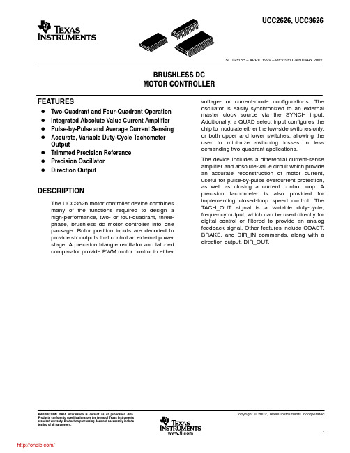
Copyright 2002, Texas Instruments Incorporated
1
/
UCC2626, UCC3626
SLUS318B – APRIL 1999 – REVISED JANUARY 2002
AVAILABLE OPTIONS TA –40_C to 85_C 0_C to 70_C PDIP (N) UCC2626N UCC3626N PACKAGED DEVICES SOIC{ (DW) UCC2626DW UCC3626DW TSSOP{ (PW) UCC2626PW UCC3626PW
† Stresses beyond those listed under “absolute maximum ratings” may cause permanent damage to the device. These are stress ratings only, and functional operation of the device at these or any other conditions beyond those indicated under “recommended operating conditions” is not implied. Exposure to absolute-maximum-rated conditions for extended periods may affect device reliability. ‡ All voltages are with respect to GND. Currents are positive into negative out of the specified terminal.
无刷直流电机控制器UCC3626的原理及应用
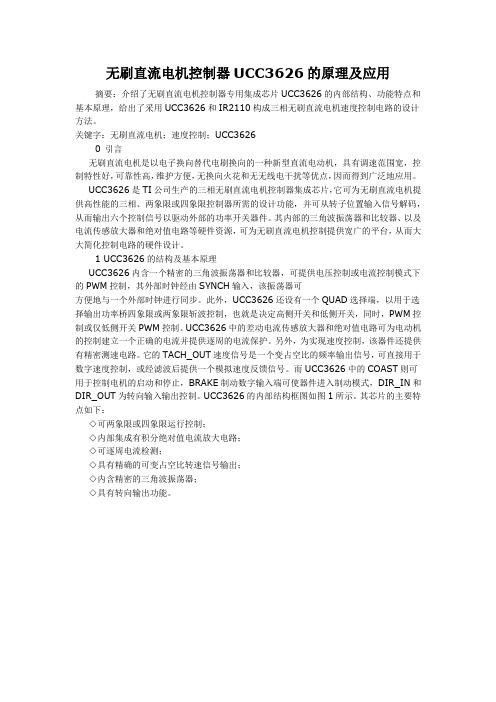
无刷直流电机控制器UCC3626的原理及应用摘要:介绍了无刷直流电机控制器专用集成芯片UCC3626的内部结构、功能特点和基本原理,给出了采用UCC3626和IR2110构成三相无刷直流电机速度控制电路的设计方法。
关键字:无刷直流电机;速度控制;UCC36260 引言无刷直流电机是以电子换向替代电刷换向的一种新型直流电动机,具有调速范围宽,控制特性好,可靠性高,维护方便,无换向火花和无无线电干扰等优点,因而得到广泛地应用。
UCC3626是TI公司生产的三相无刷直流电机控制器集成芯片,它可为无刷直流电机提供高性能的三相、两象限或四象限控制器所需的设计功能,并可从转子位置输入信号解码,从而输出六个控制信号以驱动外部的功率开关器件。
其内部的三角波振荡器和比较器、以及电流传感放大器和绝对值电路等硬件资源,可为无刷直流电机控制提供宽广的平台,从而大大简化控制电路的硬件设计。
1 UCC3626的结构及基本原理UCC3626内含一个精密的三角波振荡器和比较器,可提供电压控制或电流控制模式下的PWM控制,其外部时钟经由SYNCH输入,该振荡器可方便地与一个外部时钟进行同步。
此外,UCC3626还设有一个QUAD选择端,以用于选择输出功率桥四象限或两象限斩波控制,也就是决定高侧开关和低侧开关,同时,PWM控制或仅低侧开关PWM控制。
UCC3626中的差动电流传感放大器和绝对值电路可为电动机的控制建立一个正确的电流并提供逐周的电流保护。
另外,为实现速度控制,该器件还提供有精密测速电路。
它的TACH_OUT速度信号是一个变占空比的频率输出信号,可直接用于数字速度控制,或经滤波后提供一个模拟速度反馈信号。
而UCC3626中的COAST则可用于控制电机的启动和停止,BRAKE制动数字输入端可使器件进入制动模式,DIR_IN和DIR_OUT为转向输入输出控制。
UCC3626的内部结构框图如图1所示。
其芯片的主要特点如下:◇可两象限或四象限运行控制;◇内部集成有积分绝对值电流放大电路;◇可逐周电流检测;◇具有精确的可变占空比转速信号输出;◇内含精密的三角波振荡器;◇具有转向输出功能。
- 1、下载文档前请自行甄别文档内容的完整性,平台不提供额外的编辑、内容补充、找答案等附加服务。
- 2、"仅部分预览"的文档,不可在线预览部分如存在完整性等问题,可反馈申请退款(可完整预览的文档不适用该条件!)。
- 3、如文档侵犯您的权益,请联系客服反馈,我们会尽快为您处理(人工客服工作时间:9:00-18:30)。
UCC2626UCC3626PRELIMINARYFEATURES•Two Quadrant and Four Quadrant Operation•Integrated Absolute Value Current Amplifier•Pulse-by-Pulse and Average Current Sensing•Accurate, Variable Duty Cycle Tachometer Output•Trimmed Precision Reference •Precision Oscillator •Direction OutputBrushlessDC Motor ControllerBLOCK DIAGRAMDESCRIPTIONThe UCC3626motor controller IC combines many of the functions re-quired to design a high performance,two or four quadrant,3-phase,brushless DC motor controller into one package.Rotor position inputs are decoded to provide six outputs that control an external power stage.A precision triangle oscillator and latched comparator provide PWM mo-tor control in either voltage or current mode configurations.The oscilla-tor is easily synchronized to an external master clock source via the SYNCH input.Additionally,a QUAD select input configures the chip to modulate either the low side switches only,or both upper and lower switches,allowing the user to minimize switching losses in less de-manding two quadrant applications.The chip includes a differential current sense amplifier and absolute value circuit which provide an accurate reconstruction of motor current,useful for pulse by pulse over current protection as well as closing a current control loop.A precision tachometer is also provided for imple-menting closed loop speed control.The TACH_OUT signal is a variable duty cycle,frequency output which can be used directly for digital con-trol or filtered to provide an analog feedback signal.Other features in-clude COAST,BRAKE,and DIR_IN commands along with a direction output, DIR_OUT.ELECTRICAL CHARACTERISTICS :Unless otherwise stated, these specifications apply for VCC = 12V; CT = 1nF,R TACH = 250K,C TACH = 100pF, T A =T J , T A = –40°C to +85°C for the UCC2626, and 0°C to +70°C for the UCC3626.PARAMETERTEST CONDITIONSMINTYPMAX UNITSOverallSupply Current 310mAUnder-Voltage Lockout Start Threshold 10.5V UVLO Hysteresis 0.5V5.0 V Reference Output Voltage I VREF = –2mA 4.955.1V Line Regulation 11V <VCC < 14.5V 10mV Load Regulation –1 >I VREF > –5mA30mV Short Circuit Current 40120mACoast Input Comparator Threshold 1.75V Hysteresis 0.1V Input Bias Current0.1µAABSOLUTE MAXIMUM RATINGSSupply Voltage V DD . . . . . . . . . . . . . . . . . . . . . . . . . . . . . .+15V InputsPins 20, 19, 18, 21, 15, 16, 17, 7, 12, 9, 10. . . .–0.3V to V DD Pins 13, 14. . . . . . . . . . . . . . . . . . . . . . . . . . . .–0.3V to 8.0V Output CurrentPins 22, 23, 24, 25, 26, 27. . . . . . . . . . . . . . . . . . . . .±200mA Pins 2. . . . . . . . . . . . . . . . . . . . . . . . . . . . . . . . . . . . . .–20mA Pins 3. 8, 11. . . . . . . . . . . . . . . . . . . . . . . . . . . . . . . . . . .1mA Storage Temperature . . . . . . . . . . . . . . . . . . .–65°C to +150°C Junction Temperature. . . . . . . . . . . . . . . . . . .–55°C to +150°C Lead Temperature (Soldering 10 Seconds). . . . . . . . . .+300°CNote:Unless otherwise indicated,voltages are referenced to ground.Currents are positive into,negative out of specified ter-minal.Consult packaging section of Databook for thermal limi-tations and considerations of package.UCCPACKAGETEMPERATURE RANGEORDERING INFORMATIONTEMPERATURE RANGEPACKAGE UCC2626N DIL UCC2626DW –40°C to +85°CSOIC UCC2626PW TSSOP UCC3626N DIL UCC3626DW 0°C to +70°CSOIC UCC3626PWTSSOPELECTRICAL CHARACTERISTICS:Unless otherwise stated, these specifications apply for VCC= 12V; CT = 1nF,R TACH= 250K,C TACH= 100pF, T A=T J, T A= –40°C to +85°C for the UCC2626, and 0°C to +70°C for the UCC3626.PARAMETER TEST CONDITIONS MIN TYP MAX UNITS Current Sense AmplifierInput Offset Voltage VCM= 0V5mV Input Bias Current VCM= 0V10µA Gain VCM= 0V 4.95 5.1V/V CMRR–0.3V <VCM< 0.560dB PSRR11V <VCC<14.5V60dB Output High Voltage I IOUT= –100µA5V Output Low Voltage I IOUT= 100µA50mV Output Source Current V IOUT= 2V500µA PWM ComparatorInput Common Mode Range 2.08.0V Propogation Delay75nS Over-Current ComparatorInput Common Mode Range0.0 5.0V Propogation Delay175nS Logic InputsLogic High QUAD, BRAKE, DIR 3.5V Logic Low QUAD, BRAKE, DIR 1.5V Input Current QUAD, BRAKE, DIR0.1µA Hall Buffer InputsVIL HALLA, HALLB, HALLC1V VIH HALLA, HALLB, HALLC 1.9V Input Current0V < V IN< 5V–25µA OscillatorFrequency R TACH= 250k, C T= 1nF10KHz Frequency Change With Voltage12V <VCC< 14.5V5% CT Peak Voltage7.5V CT Valley Voltage 2.5V CT Peak-to-Valley Voltage 5.0V SYNCH Pin Minimum Pulse Width–500ns TachometerV OH/V REF I OUT= –10µA99100% Vol I OUT= 10µA020mV R ON High I OUT= –100µA1kΩR ON Low I OUT= 100µA1kΩRamp Threshold, Lo20mV Ramp Threshold, Hi 2.52VC TACH Charge Current R TACH= 49.9kΩ50µAT-on Accuracy Note 1–33% Direction OutputDIR OUT High Level I OUT= –100µA 3.5 5.1V DIR OUT Low Level I OUT= 100µA01VPIN DESCRIPTIONSAHI,BHI,CHI:Digital outputs used to control the high side switches in a three phase inverter.For specific de-coding information reference Table I.ALOW,BLOW,CLOW:Digital outputs used to control the low side switches in a three phase inverter.For spe-cific decoding information reference Table I.BRAKE:BRAKE is a digital input which causes the de-vice to enter brake mode.In brake mode all three high side outputs are turned off,AHI,BHI&CHI,while all three lowside outputs are turned on,ALOW,BLOW, CLOW.During brake mode the tachometer output re-mains operational.The only conditions which can inhibit the low side commands during brake are UVLO,ex-ceeding peak current,the output of the PWM compara-tor, or the COAST command.COAST:The COAST input consists of a hysteretic com-parator which disables the outputs.The input is useful in implementing an overvoltage bus clamp in four quadrant applications.The outputs will be disabled when the input is above 1.75V.CT:This pin is used in conjunction with the R_TACH pin to set the frequency of the oscillator.A timing capacitor is normally connected between this point and ground and is alternately charged and discharged between2.5V and 7.5V.C_TACH:A timing capacitor is connected between this pin and ground to set the width of the TACH_OUT pulse. The capacitor is charged with a current set by the resis-tor on pin RT.DIR_IN:DIR_IN is a digital input which determines the order in which the HALLA,B&C inputs are decoded.For specific decode information reference Table I.DIR_OUT:DIR_OUT represents the actual direction of the rotor as decoded from the HALLA,B&C inputs.For any valid combination of HALLA,B&C inputs there are two valid transitions,one which translates to a clockwise rotation and another which translates to a counterclock-wise rotation.The polarity of DIR_OUT is the same as DIR_IN while motoring,i.e.sequencing from top to bot-tom in Table 1.GND:GND is the reference ground for all functions of the part.Bypass and timing capacitors should be terminated as close to this point as possible.HALLA,HALLB,HALLC:These three inputs are de-signed to accept rotor position information positioned 120°apart.For specific decode information reference Ta-ble I.These inputs should be externally pulled-up to VREF or another appropriate external supply.IOUT:IOUT represents the output of the current sense and absolute value amplifiers.The output signal appear-ing is a representation of the following expression:I ABS ISENS I ISENS NIOUT=−•(__)5This output can be used to close a current control loop as well as provide additional filtering of the current sense signal.OC_REF:OC_REF is an analog input which sets the trip voltage of the overcurrent comparator.The sense input of the comparator is internally connected to the output of the current sense amplifier and absolute value circuit.PWM_NI:PWM_NI is the noninverting input to the PWM comparator.PWM_I:PWM_I is the inverting input to the PWM com-parator.ELECTRICAL CHARACTERISTICS:Unless otherwise stated, these specifications apply for VCC= 12V; CT = 1nF,R TACH= 250K,C TACH= 100pF, T A=T J, T A= –40°C to +85°C for the UCC2626, and 0°C to +70°C for the UCC3626.PARAMETER TEST CONDITIONS MIN TYP MAX UNITS Output SectionMaximum Duty Cycle100% Output Low Voltage I OUT= 10mA0.4V Output High Voltage I OUT= –10mA 4.0 5.1V Output Low Voltage I OUT= 1mA1V Output High Voltage I OUT= –1mA 4.0 5.1V Rise/Fall Time CI = 100pF100nS Note 1:T(on) is calculated using the formula:T(on) =C TACH (V HI–V LO)/I CHARGE.This number is compared to the formula T(on) = R TACH C TACH.Table 1provides the decode logic for the six outputs,AHI,BHI,CHI,ALOW,BLOW,and CLOW as a function of the BRAKE,COAST,DIR_IN,HALLA,HALLB,and HALLC inputs.The UCC3626is designed to operate with 120°position sensor encoding.In this format,the three position sensorsignals are never simultaneously high or low.Motor's whose sensors provide 60°encoding can be converted to 120° using the circuit shown in Fig. 1.In order to prevent noise from commanding improper commutation states,some form of low pass filtering on HALLA,HALLB,and HALLC is recommended.PassiveAPPLICATION INFORMATIONQUAD:The QUAD input selects between “two”QUAD =0and “four”QUAD =1quadrant operation.When in “two-quadrant”mode only the low side devices are ef-fected by the output of the PWM comparator.In “four-quadrant”mode both high and low side devices are controlled by the PWM comparator.SYNCH:The SYNCH input is used to synchronize the PWM oscillator with an external digital clock.When using the SYNCH feature,a resistor equal to R T ACH must be placed in parallel with CT.When not used,ground SYNCH.SNS_NI,SNS_I:These inputs are the noninverting and inverting inputs to the current sense amplifier,respec-tively.The integrated amplifier is configured for a gain of five.An absolute value function is also incorporated into the output in order to provide a representation of actual motor current when operating in four quadrant mode.TACH_OUT:TACH_OUT is the output of a monostable triggered by a change in the commutation state,thus pro-viding a variable duty cycle,frequency output.The on-time of the monostable is set by the timing capacitor connected to C_TACH.The monostable is capable of be-ing retriggered if a commutation occurs during it's on-time.R_TACH:A resistor connected between R_TACH and ground programs the current for both the oscillator and tachometer.VDD:VDD is the input supply connection for this device.Undervoltage lockout keeps the outputs off for inputs be-low 10.5V .The input should be bypassed with a 0.1µF ce-ramic capacitor, minimum.VREF:VREF is a 5V ,2%trimmed reference output with 5mA of maximum available output current.This pin should be bypassed to ground with a 0.1µF ceramic ca-pacitor, minimum.PIN DESCRIPTIONS (cont.)Table mutation truth table.code.RC networks generally work well and should be located as close to the IC as possible.Fig.2illustrates these techniques.Configuring the OscillatorThe UCC3626oscillator is designed to operate at fre-quencies up to 250kHz and provide a triangle waveform on CT with a peak to peak amplitude of 5V for improved noise immunity.The current used to program CT is de-rived off of the R_TACH resistor according to the follow-ing equation:I R TACHAmpsOSC =25_Oscillator frequency is set by R_TACH and CT according to the following relationship:Frequency R TACH CT Hz=•25.(_)Timing resistor values should be between 25k Ωand 500k Ωwhile capacitor values should fall between 100pF and 1µF .Fig.4provides a graph of oscillator frequency for various combinations of timing components.As with any high frequency oscillator,timing components should be located as close to the IC pins as possible when lay-ing out the printed circuit board.It is also important to ref-erence the timing capacitor directly to the ground pin on the UCC3626rather than daisy chaining it to another trace or the ground plane.This technique preventsswitching current spikes in the local ground from causing jitter in the oscillator.Synchronizing the OscillatorA common system specification is for all oscillators in a design to be synchronized to a master clock.The UCC3626provides a SYNCH input for exactly this pur-pose.The SYNCH input is designed to interface with a digital clock pulse generated by the master oscillator.A positive going edge on this input causes the UCC3626oscillator to begin discharging.In order for the slave os-cillator to function properly it must be programmed for a frequency slightly lower than that of the master.Also,a resistor equal to R T ACH must be placed in parallel with CT.Fig.3illustrates the waveforms for a slave oscillator programmed to 20kHz with a master frequency of 30kHz.The SYNCH pin should be grounded when not used.APPLICATION INFORMATION (cont.)R_TACH.oscillator waveforms.Programming the TachometerThe UCC3626tachometer consists of a precision,5V monostable,triggered by either a rising or falling edge on any of the three Hall inputs,HALLA,HALLB,HALLC.The resulting TACH_OUT waveform is a variable dutycycle square wave whose frequency is proportional to motor speed, as given by:TACH OUT V P Hz _()=•20where P is the number of motor pole pairs and V is motor velocity in RPM.The on-time of the monostable is programmed via timing resistor R_TACH and capacitor C_TACH according to the following equation:On Time R TACH C TACH −=•__secFig.5provides a graph of On-Time for various combina-tions of R_TACH and C_TACH.On-Time is typically set to a value less than the minimum TACH-OUT period as given by:T Period V PMIN MAX _sec=•20where P is the number of motor pole pairs and V is motor velocity in RPM.The TACH_OUT signal can be used to close a digital velocity loop using a microcontroller,as shown in Fig.6,or directly low pass filtered in an analog implementation,Fig.7.R_TACH.Two Quadrant vs Four Quadrant ControlFig.8illustrates the four possible quadrants of operation for a motor.Two quadrant control refers to a system whose operation is limited to quadrants I and III where torque and velocity are in the same direction.With a two quadrant brushless DC amplifier,there are no provisions other than friction to decelerate the load,limiting the ap-proach to less demanding applications.Four quadrant controllers,on the other hand,provide controlled opera-tion in all quadrants,including II and IV,where torque and rotation are of opposite direction.When configured for two quadrant operation,(QUAD=0), the UCC3626will only modulate the low side devices of the output power stage.The current paths within the out-put stage during the PWM on and off times are illus-trated in Fig.9.During the'on'interval,both switches are on and current flows through the load down to ground.During the'off'time,the lower switch is shut off and the motor current circulates through the upper half bridge via the flyback diode.The motor is assumed to be operating in either quadrant I or III.If one attempts to operate in quadrants II or IV by chang-ing the DIR bit and reversing the torque,switches1and4 are turned off and switches2and3turned on.Under this condition motor current will very quickly decay,reverse direction and increase until the control threshold is reached.At this point switch2will turn off and current will once again circulate in the upper half bridge,however,in this case the motor's BEMF is in phase with the current, i.e.the motor's direction of rotation has not yet changed. Fig.10illustrates the current paths when operating in this mode.Under these conditions there is nothing to limit the current other than motor and drive impedance.These high circulating currents can result in damage to the power devices in addition to high, uncontrolled torque.By pulse width modulating both the upper and lower power devices(QUAD=1),motor current will always de-cay during the PWM“off”time,eliminating any uncon-trolled circulating currents.In addition,current will always flow through the current sense resistor,thus providing a suitable feedback signal.Fig.11illustrates the current paths during a four quadrant torque reversal.Motor drive waveforms for both two and four quadrant operation are illustrated in Fig. 12.Power Stage Design ConsiderationsThe flexible architecture of the UCC3626requires the user to pay close attention to the design of the power output stage.Two and Four Quadrant applications that do not require the brake function are able to utilize the power stage approach illustrated in Fig.13A.In many cases the body diode of the MOSFET can be utilized to reduce parts count and cost.If efficiency is a key require-ment,Schottky diodes can be used in parallel with the switches.If the system requires a braking function,diodes must be added in series with the lower power devices and the lower flyback diodes returned to ground,as pictured in Fig.13B,C.This requirement prevents brake currents from circulating in the lower half bridge and bypassing the sense resistor.In addition,the combination of braking and four quadrant control necessitates an additional re-sistor in the diode path to sense current during the PWM 'off' time as illustrated in Fig.13C.Current SensingThe UCC3626includes a differential current sense am-plifier with a fixed gain of five,along with an absolute value circuit.The current sense signal should be low pass filtered to eliminate leading edge spikes.In order to maximize performance,the input impedance of the am-plifier should be balanced.If the sense voltage must be trimmed for accuracy reasons,a low value input divider or a differential divider should be used to maintain im-pedance matching, as shown in Fig.14.With four quadrant chopping motor current always flows through the sense resistor.However,during the flyback period the polarity across the sense resistor is reversed. The absolute value amplifier cancels the polarity reversal by inverting the negative sense signal during the flyback time,see Fig.15.Therefore,the output of the absolute value amplifier is a reconstructed analog of the motor current,suitable for protection as well as feedback loop closure.APPLICATION INFORMATION (cont.)APPLICATION INFORMATION (cont.)TYPICAL APPLICATIONSFig.16illustrates a simple175V,2A two quadrant velocity controller using the UCC3626.The power stage is de-signed to operate with a rectified off-line supply using IR2210s to provide the interface between the low voltage control signals and the power MOSFETs.The power to-pology illustrated in Fig.13C is implemented in order to provide braking capability.The controller's speed command is set by potentiometer R30while the speed feedback signal is obtained by low pass filtering and buffering the TACH-OUT signal using R11and C9.Small signal compensation of the velocity control loop is provided by amplifier U5A,whose output is used to control the PWM duty cycle.The integrating ca-pacitor,C8,places a pole at0Hz and a zero in conjunc-tion with R10.This zero can be used to cancel the low frequency motor pole and cross the loop over with a –20dB gain response.Four quadrant applications require the control of motor current.Fig.17illustrates a sign/magnitude current con-trol loop within an outer bipolar velocity loop using the UCC3626.U1serves as the velocity loop error amplifier and accepts a+/-5V command signal.Velocity feedback is provided by low pass filtering and scaling the TACH_OUT signal using U2.The direction output, DIR_OUT,switch and U3set the polarity of the tachom-eter gain according to the direction of rotation.The out-put of the velocity error amplifier,U1,is then converted to sign/magnitude form using U5and U6.The sign por-tion is used to drive the DIR input while the magnitude commands the current error amplifier,U8.Current feed-back is provided by the internal current sense amplifier via the IOUT pin.TYPICAL APPLICATION (cont.)TYPICAL APPLICATIONS (cont.)UCC2626 UCC3626Figure 16.Two quadrant velocity controller.UCC2626UCC3626 TYPICAL APPLICATIONS (cont.)UNITRODE CORPORA TION7 CONTINENT AL BLVD.• MERRIMACK, NH 03054TEL.(603) 424-2410 • FAX (603) 424-3460IMPORTANT NOTICETexas Instruments and its subsidiaries (TI) reserve the right to make changes to their products or to discontinue any product or service without notice, and advise customers to obtain the latest version of relevant information to verify, before placing orders, that information being relied on is current and complete. All products are sold subject to the terms and conditions of sale supplied at the time of order acknowledgement, including those pertaining to warranty, patent infringement, and limitation of liability.TI warrants performance of its semiconductor products to the specifications applicable at the time of sale in accordance with TI’s standard warranty. Testing and other quality control techniques are utilized to the extent TI deems necessary to support this warranty. Specific testing of all parameters of each device is not necessarily performed, except those mandated by government requirements.CERTAIN APPLICATIONS USING SEMICONDUCTOR PRODUCTS MAY INVOLVE POTENTIAL RISKS OF DEATH, PERSONAL INJURY, OR SEVERE PROPERTY OR ENVIRONMENTAL DAMAGE (“CRITICAL APPLICATIONS”). TI SEMICONDUCTOR PRODUCTS ARE NOT DESIGNED, AUTHORIZED, OR WARRANTED TO BE SUITABLE FOR USE IN LIFE-SUPPORT DEVICES OR SYSTEMS OR OTHER CRITICAL APPLICATIONS. INCLUSION OF TI PRODUCTS IN SUCH APPLICATIONS IS UNDERSTOOD TO BE FULLY AT THE CUSTOMER’S RISK.In order to minimize risks associated with the customer’s applications, adequate design and operating safeguards must be provided by the customer to minimize inherent or procedural hazards.TI assumes no liability for applications assistance or customer product design. TI does not warrant or represent that any license, either express or implied, is granted under any patent right, copyright, mask work right, or other intellectual property right of TI covering or relating to any combination, machine, or process in which such semiconductor products or services might be or are used. TI’s publication of information regarding any third party’s products or services does not constitute TI’s approval, warranty or endorsement thereof.Copyright © 1999, Texas Instruments Incorporated。
