知用EMI接收机EM5080A(9kHz-30MHz)概述
EMI接收机EM5080A全数字化预认证级
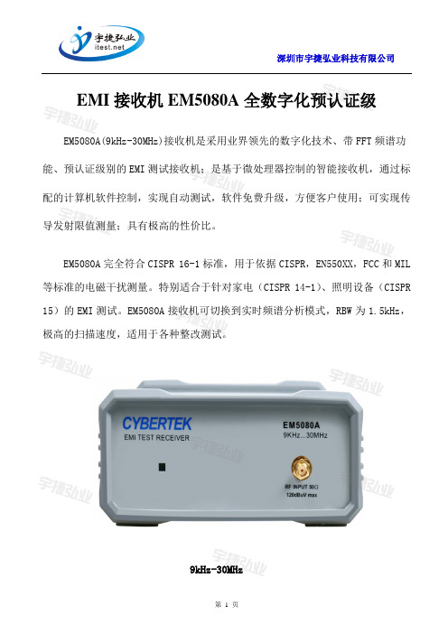
EMI接收机EM5080A全数字化预认证级EM5080A(9kHz-30MHz)接收机是采用业界领先的数字化技术、带FFT频谱功能、预认证级别的EMI测试接收机;是基于微处理器控制的智能接收机,通过标配的计算机软件控制,实现自动测试,软件免费升级,方便客户使用;可实现传导发射限值测量;具有极高的性价比。
EM5080A完全符合CISPR 16-1标准,用于依据CISPR,EN550XX,FCC和MIL 等标准的电磁干扰测量。
特别适合于针对家电(CISPR 14-1)、照明设备(CISPR 15)的EMI测试。
EM5080A接收机可切换到实时频谱分析模式,RBW为1.5kHz,极高的扫描速度,适用于各种整改测试。
9kHz-30MHz一、产品特点◆CISPR 16-1-1标准全兼容准峰值检波器低至2Hz PRF(A波段),B波段低至10Hz◆业界领先的软件无线电技术SDR (Software Defined Radio)构建平台, 高精度高稳定性◆高速高精度AD+FPGA; 全数字DDC变换; 全数字中频滤波器◆全数字峰值、准峰值、CISPR 平均值◆标配频谱分析模式,实时观察结果, 便于工程师快速进行EMI的整改◆免费测试软件,基于Windows平台, 使用方便,用户可自行下载最新软件◆选用近场探头EM5030,在设计调试阶段查找发射源以及泄漏◆选用内置限幅器的人工电源网络EM5040A或共模差模分离的人工电源网络EM5040B, 完成传导发射限值测量和分析二、产品参数频率范围9kHz-30MHz频率分辨率1Hz测量精度<1ppm射频输入50Ω,SMA fem.VSW R 30dB RF att. <1.2 0dB RF att. <2衰减0dB—30dB 测量精度±1.5dB典型最大输入电平(设备无损坏)正选交流电压120dBuV脉冲频率密度+97dBμV/MHz 预选器固定带通滤波器LP-150kHz150kHz-4.05MHz 4.05MHz-12.8MHz 12.8MHz-21.55MHz 21.55MHz-30MHzIF带宽6dB 0.2和9kHz (CISPR 16-1-1) 噪声电平9kHz-150kHz (200Hz BW) <0dBμV(QP)典型<-5dBμV(AV)典型150kHz-30MHz (9kHz BW) <8dBμV(QP)典型<0dBμV(AV)典型检波器峰值、准峰值、CISPR 平均值CISPR 16-1-1标准A波段全兼容准峰值检波器低至2Hz PRF B波段全兼容准峰值检波器低至10Hz PRF测试时间(驻留时间) PK/AV:5-500ms 可调QP:1s-15s可调镜像抑制90dB典型显示单位dBμV dBm 实时FFT频谱分析模式 1.5kHz RBW通信接口USB2.0供电DC12V/1A工作温度0℃~45℃尺寸193*134*58mm 重量1kg三、产品说明前面版:后面版:1.射频输入口:50Ω,SMA female.2.LED灯:电源指示灯,绿色。
EMI接收机规范的剖析

EMI接收机规范的剖析按定义,任何符合CISPR 16,Part 1要求的设备,都可视为可进行符合性测试的EMI接收机WERNER SCHAEFERHewlett-Packard CompanySanta Rosa,CA大多数的商用EMI标准引用了CISPR Publication 16,Part 1来规范EMI和EMS测试设备。
本文将会讨论最重要的接收机规范,总结预期附加的规范,并且讨论频谱仪用于符合性测试时的一些限制。
正在修订中的CISPR16,part1将技术规范扩展到了1GHz到18GHz。
这也将会在文中讨论到。
CISPR16,Part1目前的版本发布于1993年8月,其中规定了接收机在9KHz 到1GHz的技术规范。
其中包括输入阻抗,检波器特性和中频(IF)带宽形状,同时也规定了测量正弦波和不同重复周期的脉冲信号的幅度精度。
另外,还对接收机的杂散响应,镜像和中频抑制,互调失真以及屏蔽效能有附加的要求。
CISPR16,PART1(08-93)中的接收机规范输入阻抗接收机输入阻抗规定为50Ω,可接受的与正常值的偏离是以VSWR(电压驻波比)的形式给出。
匹配比较好的输入衰减器能够改善接收机的VSWR,因此规范中提出了两种衰减器的设置:0dB和10dB或者更大。
此性能会直接影响EMI测量的总的不确定度。
分辨率带宽在不同的频段测量需要使用不同的分辨率带宽。
一般情况下,通常以带宽(比如3dB带宽)及来描述接收机的中频滤波器性能,其中频率响应是指滤波器的波形因子(比如60dB和3dB带宽比)或者是频响特性必须满足的一个框架(图1)。
CISPR16,PART1中所规定的6dB带宽为:● 200Hz 9KHz至150KHz● 9kHz 150kHz至30MHz● 120kHz 30MHz至1GHz此外,对于每个滤波器,框架通常以相对于滤波器中心频率偏移一定频率值的插入损耗的形式给出。
此框架的规定使中频滤波器的幅度响应特性的定义就更加完整。
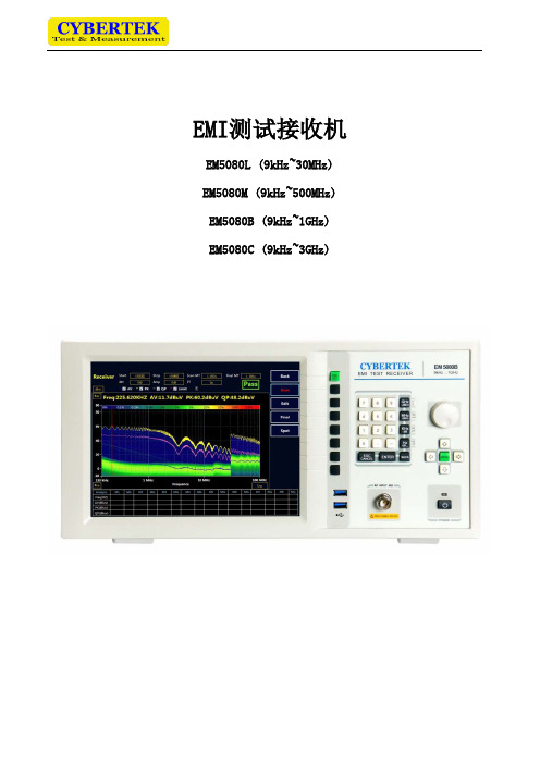
EM5080 数字接收机说明书
按键可以实现下图中菜单栏的显示和隐藏。
6、显示主界面说明
EM5080B/C 主界面如下图所示:
标号 1 2 3 4
5
名称 当前模式为“接收机”模式
内置衰减器设置 当前起始频率和终止频率
前置放大器状态指示
裕量值
说明 可使用右侧软按键切换成频谱模式。(标号 10 处)
0-50 可选,步进 10dB。 使用鼠标或者方向按键,“ENTER”按键,配合数字按键进行设置。 使用鼠标或者方向按键,“ENTER”按键进行设置。有 0dB 和 20dB 两档可选。 “-6”表示离标准线留有 6dB 裕量,用户可根据需要更改参数。使用鼠标或者方向按键,
14
Y 轴量程设置
15
数据表格。
使用鼠标或者方向按键,“ENTER”按键进行设置。 会自动显示超过裕量的频点的值,手动添加的值也会在该数据表格中显示。
表 4:显示界面说明
7、接收机模式说明
接收机主界面
标号 1 2 3 4 5 6 7
名称 复位键
开始或者停止扫描 扫描结果编辑 终测 快速生成报告 定点测试功能 返回
表 2:后面板说明
4、技术规格
频率范围
电平 最大射频电平(CW) 最大脉冲电压
EM5080L EM5080M EM5080B EM5080C
射频衰减≥10dB; 射频前置放大器关闭 射频衰减≥10dB
9kHz 到 30MHz 9kHz 到 500MHz 9kHz 到 1GHz 9kHz 到 3GHz
说明 复位软件到初始状态 在扫描运行过程中不要进行相关设置工作,在停止后进行设置 可以对扫描的数据进行编辑,包括峰值查找,添加和删除频点等 可以对数据表中的频点进行终测测试 快速生成检测报告 进入 Spot 模式,单点测量
全数字EM5080A接收机和模拟对比精品文档17页
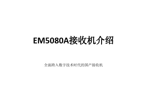
实时频谱界面
接收机界面
200HZ/9KHZ,和模拟滤波器相 比可以实现理想的高斯滤波器。带宽精度高,无附加 的噪声没有温度或老化漂移,电平精度高
• 4:数字包络线检波器无附加的噪声没有温度或老化 漂移电平精度高
5:PK/AV/QP测量电路可同时使用三个检波器 QP/AV/PK,无附加的噪声没有温度或老化漂移电平
由复杂模拟分立元件构成
性能对比
• 国产模拟接收机 • 混频器、滤波器、多
级放大器、检波器, PK/AV/QP测量电路等 模块构成
• 有大量的电位器/可调 电感/可调电容/模拟电 路等
• 精度的离散性大 ,需 要精确调试。
• 精度随时间和温度漂 移很大
• EM5080A
• 混频器、滤波器、多级放 大器、检波器PK/AV/QP测 量电路等模块,全部是 FPGA数字实现。
软件无线电技术介绍
•射频直采Direct-sampling: 9K—30MHZ的射 频信号进入AD直接采样 •数字下变频DDC:数字下变频(Digital Down Converter )是软件无线电的核心技术之一, 用数字的方法实现如FPGA将射频信号变换到 基带信号,再测出信号的值 。
EM5080A的数字板
国产模拟接收机
•国产模拟接收机是一种传统的超外差接收机, 是利用本地产生的振荡波与输入信号混频, 将输入信号频率变换为某个预先确定的中频 频率的方法。然后对这个频率进行检波, PK/AV/QP测量电路,最后通过AD读出信号的 值。超外差原理最早是由E.H.阿姆斯特朗于 1918年提出的。
飞思卡尔半导体 面向电子阅读器的i.MX508处理器 说明书
目录一、概述二、端口定义及输出说明三、按键定义四、按键功能与操作说明五、工厂调试与设置六、特殊功能说明一、概述使用该CPU配合LA76810或LA76818使用,可实现TV+DVD二合一控制功能,也可只作为单TV时使用。
该CPU还具有多种功能扩展,可实现从简单到高档全系列机芯。
下面是该CPU的硬件特性及软件所具备功能的简介。
1-1、LC8635XX的硬件特性1.512×8 bits RAM。
2.16K~64K ROM可选。
3.OSD 功能l屏幕显示:16行×36列;l显示RAM:176×9 bits;l248个18×32点阵字符;l8种字符颜色,8种背景颜色,8种全屏颜色可选。
4.CPU最小指令周期0.85μs。
5.24个I/O端口(输入、输出可定义)。
6.4个6 bit A/D转换器。
7.3个7 bit PWM输出口。
8.2组IIC控制端口。
9.16-bit定时器/计数器。
10.16-bit定时器/PWM。
11.红外接收电路(内藏消噪电路)。
12.13个中断源,8个中断入口,三级中断优先权。
13.最大可实现128级子程序调用。
14.可实现ROM校正功能。
15.CPU Standby 功能。
16.晶振32.768KHZ(低时钟干扰)。
17.+5V±5%单电源输入。
18.36 pin、S-DIP封装。
1-2、软件实现功能1.配合LA76810或LA76818使用,可实现TV+DVD二合一控制功能。
2.全频段14 bits PWM调谐输出控制电压合成高频头。
也可选用频率合成高频头。
3.可根据EEPROM(AT24C04或AT24C08)自动选择实现100或255个存台数。
冷开机时,可对EEPROM实现检测功能,如出错就警告。
如果更换新的EEPROM,则自动写入初始化数据。
4.设置项均通过软件来实现,结果存于EEPROM中,根据不同的设置可实现不同的功能。
空气净化器传导骚扰EMI测量系统

传导统。
使用EMI 接收导骚扰(E一、测量参考标准设备名称EMI 接收EM5080L 人工电源EM5040A 隔离变压EM5060空气导骚扰(EMI)测用线路阻抗稳收机来测量频EMI)测量系统量设备选型:准:GB4343-2称规收机L/M/B频E E E 精源网络A/B电最频9压器最气净化测试系统,是稳定网络(LISN 频率与强度。
统。
2009/EN5501规 格频率: EM5080L:9kH EM5080M:9kH EM5080B:9kH 精度:≤1.5电源电压:2最大电流:1频率范围: 9kHz-30MHz最大功率:9器传导是对从连接在N/ISN)检测出通过相关标准4 家用电器、Hz-30MHz Hz-500MHz Hz-1GHz 5dB 240V6A 900W导骚扰在被测物上的出设置在电波准判定是否符、电动工具和备 注M5080L 度非常EM5040EM5040扰(EMI)的电缆中传递波屏蔽室内的符合要求。
本和类似器具的注L/M/B 系列为常快,传导测0A(有限幅器0B(有限幅器选件)测量系递的传导性噪的试验品的传本文为大家介的电磁兼容要为数字时域接量可在 1s 内器)器且增加共差模(安全考虑系统声强度的测试传导性骚扰信介绍一下空气要求。
接收机,扫描内完成。
模输出接口))试评价系信号,通过 气净化器传描速)二、典型的参考实验布置:家用电器是我们常见的产品,下面以某厂家的空气净化器为例,研究测量时该如何布置,实现传导测量。
空气净化器则属于不接地的非手持式器具。
(1)场地布置说明✧参考接地平板至少超出受试器具边缘 0.5m,尺寸至少为 2m*2m✧器具应该放在水平金属接地平板上(参考接地平板),高度为 0.1mm±25%的非金属支撑隔开(例如平板架)✧引线应该沿着受试器具向下至非金属支撑面高度水平地连接到 V 型人工电源网络,器具应与人工电源网络之间的距离为 0.8m✧如果被测器具的电源引线超过连接到 V 型人工电源网络的所需长度,应该将超出 0.8m 的部分平行于电源引线来回折叠形成一个长 0.3m-0.4m 的线束(2)实测对比下面以某客户的空气净化器为测量案例,分析在普通测量环境和实验室标准测量环境下的测试结果,判断测量结果是否具有一致性,在普通环境下是否能满足预测试要求。
Fluke公司5080A MEG Megohm Option说明书
September 2010 (Simplified Chinese)© 2010 Fluke Corporation. All rights reserved. Specifications are subject to change without notice. All product names are trademarks of their respective companies.5080A/MEGMegohm Option用户手册有限担保及责任范围Fluke 公司保证其每一个Fluke的产品在正常使用及维护情形下,其用料和做工都是毫无瑕疵的。
保证期限是一年并从产品寄运日起开始计算。
零件、产品修理及服务的保证期是 90 天。
本保证只提供给从 Fluke 授权经销商处购买的原购买者或最终用户,且不包括保险丝、电池以及因误用、改变、疏忽、或非正常情况下的使用或搬运而损坏(根据 Fluke 的意见而定)的产品。
Fluke 保证在 90 天之内,软件会根据其功能指标运行,同时软件已经正确地被记录在没有损坏的媒介上。
Fluke 不能保证其软件没有错误或者在运行时不会中断。
Fluke 仅授权经销商将本保证提供给购买新的、未曾使用过的产品的最终用户。
经销商无权以 Fluke 的名义来给予其它任何担保。
保修服务仅限于从 Fluke 授权销售处所购买的产品,或购买者已付出适当的Fluke国际价格。
在某一国家购买而需要在另一国家维修的产品,Fluke 保留向购买者征收维修/更换零件进口费用的权利。
Fluke 的保证是有限的,在保用期间退回 Fluke 授权服务中心的损坏产品,Fluke有权决定采用退款、免费维修或把产品更换的方式处理。
欲取得保证服务,请和您附近的Fluke服务中心联系,或把产品寄到最靠近您的Fluke服务中心(请说明故障所在,预付邮资和保险费用,并以 FOB 目的地方式寄送)。
N9038A MXE EMI接收器数据手册说明书

1981N9038A MXE EMI Receiver20 Hz to 8.4 and 26.5 GHzData SheetTable of ContentsDefinitions and Conditions (3)Frequency and Time Specifications (4)Amplitude Accuracy and Range Specifications (7)Dynamic Range Specifications (10)PowerSuite Measurement Specifications (15)General Specifications (16)Inputs and Outputs (18)I/Q Analyzer .....................................................................................................................20 Express your insight When you’re testing a new prod-uct, the designers are counting on your expertise and advice. That’s why the Agilent MXE is more than a CISPR-compliant EMI receiver. We’ve also included X-Series signal analysis and graphical measure-ment tools that make it easy to examine signal details. With these diagnostic capabilities, the MXE complements your knowledge and helps you advise the designers if a device fails compliance testing. Equip your lab with the MXE—and express your insight.2Definitions and Conditions Specifications describe the performance of parameters covered by the productwarranty and apply to the full temperature range of 0 to 55 °C, unless otherwise noted.95th percentile values indicate the breadth of the population (approx. 2 σ) of performance tolerances expected to be met in 95 percent of the cases with a 95 percent confidence, for any ambient temperature in the range of 20 to 30 °C. In addition to the statistical observations of a sample of instruments, these values include the effects of the uncertainties of external calibration references. These values are not warranted. These values are updated occasionally ifa significant change in the statistically observed behavior of production instruments is observed.Typical describes additional product performance information that is not covered by the product warranty. It is performance beyond specifications that 80 percent of the units exhibit with a 95 percent confidence level over the temperature range 20 to 30 °C. Typical performance does not include measurement uncertainty. Nominal values indicate expected performance, or describe product performance that is useful in the application of the product, but are not covered by the product warranty.The receiver will meet its specifications when:• It is within its calibration cycle• Under auto couple control, except when Auto Sweep Time Rules = Accy • Signal frequencies < 10 MHz, with DC coupling applied• The receiver has been stored at an ambient temperature within the allowed operating range for at least two hours before being turned on• The receiver has been turned on at least 30 minutes with Auto Align set to normal, or, if Auto Align is set to off or partial, alignments must have been run recently enough to prevent an Alert message; if the Alert condition is changed from “Time and Temperature” to one of the disabled duration choices, the receiver may fail to meet specifications without informing the user This data sheet is a summary of the complete specifications and condi-tions, which are available in the MXE EMI Receiver Specification Guide. The MXE EMI Receiver Specification Guide can be obtained on the Web at: /find/mxe_specifications For ordering information, refer to the MXE EMI Receiver Configuration Guide (5990-7419EN).3Frequency and Time Specifications1. Horizontal resolution is span/(sweep points – 1).4561. Analysis bandwidth is the instantaneous bandwidth available around a center frequency over which the input signal can be digitized for further analysis or processing in the time, frequency, or modulation domain.2. Sweep points = 101.Amplitude Accuracy and Range Specifications1. DC coupling required to meet specifications below 50 MHz. With AC coupling, specifications apply at frequencies of 50 MHz and higher. Statisticalobservations at 10 MHz with AC coupling show that most instruments meet the DC-coupled specifications, however, a small percentage of instrumentsare expected to have errors exceeding 0.5 dB at 10 MHz at the temperature extreme. The effect at 20 to 50 MHz is negligible but not warranted.781. DC coupling required to meet specifications below 50 MHz. With AC coupling, specifications apply at frequencies of 50 MHz and higher. Statisticalobservations at 10 MHz with AC coupling show that most instruments meet the DC-coupled specifications, however, a small percentage of instruments are expected to have errors exceeding 0.5 dB at 10 MHz at the temperature extreme. The effect at 20 to 50 MHz is negligible but not warranted.9Dynamic Range Specifications1. Typical DANL including NFE = Typical DANL-DANL improvement with NFE2. Specified for instruments with prefixes MY/SG5213 or greater. Nominal for instruments with earlier prefixes.101. Typical DANL including NFE = Typical DANL-DANL improvement with NFE.2. No NFE factor at this frequency.3. Specified for instruments with prefixes MY/SG5213 or greater. Nominal for instruments with earlier prefixes.1. Typical Indicated Noise including NFE = Typical DANL+ Bandwidth and Log corrrections-DANL improvement with NFE2. No NFE factor at this frequency.3. Specified for instruments with prefixes MY/SG5213 or greater. Nominal for instruments with earlier prefixes.1. Preamp input power = input power-input attenuation (–9 dB for input 2).2. For nominal values, refer to Figure 1.Figure 1. Nominal phase noise at different center frequenciesPowerSuite Measurement SpecificationsGeneral Specifications1. Noise Floor Extension (NFE) required for isolated pulse in bands C and D only.Inputs and OutputsI/Q Analyzer /find/mxe For more information on Agilent Tech-nologies’ products, applications or services, please contact your local Agilent office. The complete list is available at:/find/contactus Americas Canada (877) 894 4414 Brazil (11) 4197 3600Mexico 01800 5064 800 United States (800) 829 4444 Asia Pacific Australia 1 800 629 485China 800 810 0189Hong Kong 800 938 693India 1 800 112 929Japan 0120 (421) 345Korea 080 769 0800Malaysia 1 800 888 848Singapore 180****8100Taiwan 0800 047 866Other AP Countries (65) 375 8100 Europe & Middle East Belgium 32 (0) 2 404 93 40Denmark 45 45 80 12 15Finland 358 (0) 10 855 2100France 0825 010 700* *0.125 €/minute Germany 49 (0) 7031 464 6333 Ireland 1890 924 204I srael 972-3-9288-504/544Italy 39 02 92 60 8484Netherlands 31 (0) 20 547 2111Spain 34 (91) 631 3300Sweden 0200-88 22 55United Kingdom 44 (0) 118 927 6201For other unlisted countries: /find/contactus Revised: January 6, 2012Product specifications and descriptions in this document subject to change without notice.© Agilent Technologies, Inc. 2012Published in USA, July 26, 20125990-7421EN Agilent Advantage Services is committed to your success throughout your equip-ment’s lifetime. To keep you competitive, we continually invest in tools and processes that speed up calibration and repair and reduce your cost of ownership. You can also use Infoline Web Services to manage equipment and services more effectively. By sharing our measurement and service expertise, we help you create the products that change our /quality /find/advantageservices /find/emailupdates Get the latest information on the products and applications you select. LAN eXtensions for Instruments puts the power of Ethernet and the Web inside your test systems. Agilent is a founding member of the LXI consor-tium.Agilent Channel Partnersw w w /find/channelpartners Get the best of both worlds: Agilent’s measurement expertise and product breadth, combined with channel partner convenience.。
EMI检测设备

按
进入接收机模式。(开机默认进入接收机模式)。
设置“起始频率”,“终止频率”,“扫描模式下单点测量时间”,“终测模式下单点测量时间”以及“裕 量”。(设置方法可参考表 4)
8
深圳市优测科技有限公司
选择测试标准。按下
按键,显示菜单栏,使用鼠标选择“Set”----“Limit”----“Select Limit”,
余辉模式状态指示
使用鼠标或者方向按键,“ENTER”按键进行开关设置。
终测模式下单点测量时间 使用鼠标或者方向按键,“ENTER”按键配合数字按键进行设置。
当前曲线标准指示
复位,频谱,接收机模式选择 键
在主菜单中可选择或者添加不同的标准。详见“如何添加新的 标准曲线”。
配合软按键切换接收机和频谱模式。
1
深圳市优测科技有限公司
2、特点
全数字化预认证级时域接收机。 包含了 EMI 测试接收机和实时频谱分析仪。 FFT 时域扫描以极高速度测量电磁干扰。 带宽可高达 10MHz 的实时频谱分析。 符合 CISPR 16-1-1 版要求,含所有符合 CISPR 标准的分辨率带宽。 预选器并集合 20dB 前置放大器。 清晰的 10.4 吋大液晶屏和结构化菜单,容易操作。
②对扫描结果进行编辑分析 在接收机主菜单下,点击
按键,进入扫描曲线编辑界面,如下图:
标号 1 2
说明 移动光标:可以直接输入想要添加或者查看的频点,光标会自动根据用户选择的频点显示相 应位置数据。 查找峰值:查找曲线上的峰值数据,再次点击,实现下一个峰值的自动查询。
3 将光标处的频点添加到数据表格中。
部清空。在上方的表格处会实时显示绘制的曲线。 Save 即可。 ②绘制 AV 曲线
EM5015EMI电源滤波器说明书

在错误操作的情况下,用户有受伤的危险。为避免此类危险,记载了相关的 注意事项。
注意
错误操作时,用户有受轻伤和物质损害的可能。为避免此类情况,记载了相 关的注意事项。
Note 记载着使用该机器时的重要说明。
该产品是按国际通行的 EMC 标准设计的,因此原理上会存在较大的对地漏电流。如接地不良可能会 造成严重的触电事故甚至伤亡。因此,本公司要求用户 必须保证仪器良好接地(在侧面和后面各有接地点) 很多用户的用电环境存在接地不良的情况,而用户自己并不了解。这种情况很危险,因此本公
2
五、使用注意事项
使用过程中不要打开外壳,不要在潮湿,有易燃易爆物品的的地方使用。使用前保证 仪器表面的干燥和清洁。
测试前,确定接地良好,请仔细阅读说明书,了解安全方面知识,按照正确步骤测量。 如果产品出现问题,请及时与我公司联系。请不要擅自打开外壳进行维修,以免发生
意外。
六、装箱单
装箱单 名称 滤波器本体 AC 电源线 说明书 保修卡
司要求用户必须安装隔离变压器作为双重保障。用户可以在市面上自行购买。也可以使用本公 司容量为 0.9kVA 的隔离变压器 EM5060。该产品可以满足大部分小功率测试需求。 使用过程中不要打开外壳和试图接线。也不要在潮湿或有易燃易爆物品的的地方使用。使用前 保证仪器表面的干燥和清洁。 确保产品在额定电压额定电流范围内使用。 如果产品出现问题,请及时与我公司联系。请不要擅自打开外壳进行维修,以免发生意外
9kHz—30MHz 单相 0~230V AC +10% 50 / 60Hz ±5% 0~400V DC 0~10A 国标公座 X2(一路 EUT;另一路测试设备) 国标母座 5℃~45℃ 320mm(长)×125mm(宽)×80mm(高) 1.15kg
Keysight N9038A MXE EMI接收器产品简介说明书
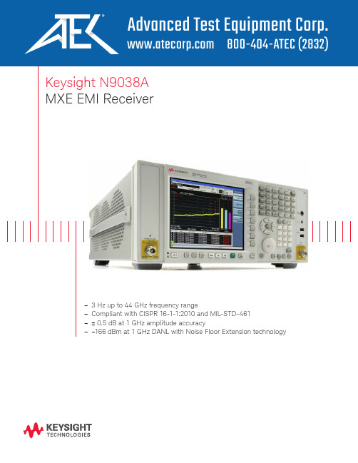
Keysight N9038AMXE EMI Receiver–3 Hz up to 44 GHz frequency range–Compliant with CISPR 16-1-1:2010 and MIL-STD-461–± 0.5 dB at 1 GHz amplitude accuracySummary of Key SpecificationsThe X-Series difference Future-readyOptimize your investment and extend instrument longevity with upgradeable processor, memory, connectivity, and more to keep your test assets current today and tomorrow.Consistent measurement frameworkAchieve measurement integrity across your organization and drive more productivity in less time by leveraging a proven foundation for signal analysis and identical operation across the X-Series instruments.Broadest set of applicationsAddress the changing demands of technology with additionalmeasurement applications, the ability to run software inside the openWindows operating system, and a first-to-market track record in emerging standards.Stay ready, stay in sync, and arrive ahead —with the Keysight X-Series./find/X-SeriesKeep the Test Queue FlowingIn EMC testing, success depends on tools that can help you do more in less time—today and tomorrow. That’s why we created the MXE: it’s a standards-compliant EMI receiver and diagnostic signal analyzer built on an upgradeable platform. In the lab and on the bench, it provides the accuracy, repeatability,and reliability you need to test with confidence.The MXE makes it easy to test in accordance with CISPR 16-1-1:2010 and MIL-STD-461. Choose the frequency coverage you need—up to 3.6, 8.4, 26.5, or44 GHz—and fully test devices with outstanding accuracy and excellent sensitivity across the required ranges.Through the front panel or remotely with software, you can evaluate emissions and identify suspect signals using EMC measurements and a variety of intuitive displays. The extensive set of built-in analysis tools helps you diagnose the causes of noncompliant emissions.With all these capabilities and more, the MXE enables you and your team to keep the test queue flowing.Extend instrument longevity with easy upgradabilityTo keep your instrument current and extend its longevity, the MXE offers easy upgradability of hardware and software capabilities. For example, you can enhance platform performance through CPU and memory upgrades, and add functionality with a simple license key.Leverage the proven reliability of a mature hardware platform Uptime is essential in a test lab and that’s why we built the MXE on the robust Keysight X-Series signal analyzer platform. In addition, the MXE carries the benefits of Keysight’s standard three-year warranty and responsive service and support team.The MXE is ideally suited for high-performance EMC testing in commercial and military applications. The instrument offers a range of CISPR- and MIL-STD-compliant capabilities—detectors, bandwidths, and more—as well as features that further enhance the accuracy and throughput of EMC testing and data analysis.Simplify setupThe MXE contains a number of features that simplify the setup process for compliance measurements. For example, you can use setup tables to create specific measurement configurations for a variety of frequency ranges and antennas. You can also reduce overall setup time by saving and recallingfrequently used custom instrument settings. In addition, the MXE can remotely control switching functions in external LISNs.To accelerate identification of suspect emissions, access the built-in library of limit lines and activate the relevant regulatory limits. You can also define custom limit lines with the easy-to-use editor. To ensure appropriate limit testing, the MXE can automatically correct measured amplitudes for specific transducers, antennas, cabling, and external preamplifiers using customer-configured amplitude correction files.Accelerate data collectionThe MXE is designed to help you see signal activity—quickly and easily—from multiple perspectives. The comprehensive user display allows you to see both a broad overview of the emissions environment and a detailed view of the signal amplitude at a single frequency.Easily capture emissions data using built-in automated scan, search, and measure functions that mirror recommended commercial and military testing procedures. The multi-trace and max hold capabilities let you view emissions from the current position of the device under test (DUT) along with themaximum emissions from all DUT positions. During monitoring, the three color-coded detectors are updated simultaneously to ensure accurate results.The MXE receiver display provides a simplified view into the emissions performance of the DUT.Maximize Throughput in Compliance TestingChoose from traditional frequency or rapid time domain scanning.Easily identify suspect signalsWith built-in measurement and analysis functions, the MXE makes it easy to identify suspect emissions. For example, the unique color-coded trace display capability clearly identifies signals that exceed the selected limit lines and margins.When creating suspect lists, you can choose between traditional frequency scanning and rapid time domain scanning. Time domain scans significantly reduce the time needed to create a list of suspect emissions prior to making final measurements.Built-in limit testing makes it easy to create emission suspect lists. The receiver can automatically move out-of-limit signals to the signal list, where you can perform measurements with the touch of a button.Simplify final measurementsThe list function in the MXE makes it easy to perform final emissionsmeasurements for all supported standards. When you need to control tower or turntable position, internal frequency lists can be passed to automationsoftware. When orientation optimization isn’t required, built-in capabilities help you complete final measurements with ease.When final measurements are complete, you can conveniently create reports in HTML or PDF format with customized content that includes amplitude corrections, limits, scan tables, trace data, signal lists, and screen shots.All-digital IF architectureA digital intermediate frequency (IF) receiver architecture improvesmeasurement accuracy. By comparison, an analog IF architecture implements gain blocks, log amps, resolution bandwidths, and detectors with analog hardware. Even the best of these designs exhibit performance differences when receiver settings are changed from the settings used for calibration. These differences are then exacerbated over temperature.The all-digital IF architectureincludes digital realizations of the key components, which operate on the signal after it has been digitized. Digital IF can improve EMC measurement throughput by minimizing the need for users to bring the signal being measured to the top of the reference level. Analog receivers require this step for every measurement to minimize the effects of analog hardware errors.In addition, digital IF architecturereduces the occurrence of IF overload, even if signals are above the reference level.As an EMI receiver and diagnostic signal analyzer, the MXE puts a wealth of capabilities at yourfingertips. New receiver technology reduces measurement time and ensures you are prepared for future requirements.Go faster with time domain scanningThe MXE offers three types offrequency scanning: swept, stepped, and time domain. Time domain scan decreases total test time by reducing overall prescan collection times when longer measurement dwell times are required.Time domain scan speedsmeasurements by using high-overlap fast Fourier transforms (FFTs) tocollect emissions data simultaneously over an acquisition bandwidth that is multiple resolution bandwidths wide. This is in contrast to frequency-domain measurements, whichcollect data in individual resolution bandwidths.With time domain testing, you can collect suspect lists rapidly, greatly improving overall test time and throughput.Automate click measurementsUse the MXE's built-in disturbance analyzer to easily make discontinuous disturbance, or click, measurements as specified in CISPR 14-1. Simplify and automate data collection, analysis, and report generation for these commonly tested emissions for more efficient testing.Enhance Your Lab with the Latest CapabilitiesComparison of resolution and FFT acquisition bandwidths.FrequencyA m p l i t u d eFFT acquisition bandwidthA m p l i t u d eFrequencyReceiver resolution bandwidthSwept or stepped frequency domain scanTime domain scanDwell for each resolution bandwidthDwell for each FFT bandwidth (multiple resolution bandwidth)Simplify and automate data collection, analysis, and report generation for click measurements.Be ready for APD measurementsThe MXE helps future-proof your lab by offering the amplitude probability distribution (APD) function that is being considered by CISPR foremissions testing of microwave ovens. To characterize slowly-varyingemissions, the APD function displays the probability of an emissionreaching or exceeding a given level. To facilitate use of this new function, the MXE also offers specific limit-line types that can be used with built-in evaluation capabilities to simplify DUT testing.Find the maximum with monitor spectrumIn EMC testing, capturing the maximum value of each emissionfrequency is crucial. Doing so enables accurate characterization of the DUT.To ensure that you have identified the frequencies of maximum emissions in your suspect list, the MXE offers a new feature called monitor spectrum. This feature offers both live-spectrum and meter displays that make it easy to see emission levels and find the maximum while adjusting the center frequency. Ultimately, monitor spectrum improves overall measurement time by reducing the time it takes to prepare your signal list for final measurements.Monitor spectrum identifies frequency of peak emissions.Be ready for future applications with the APD function.The global center frequency feature lets you easily track signals in both the receiver and spectrum analyzer.Gain Insight with Extensive Diagnostic CapabilitiesVerifying product compliance is just one facet of EMI testing. Solving emissions problems can present a wide range of challenges, and the MXE offers a number of tools that will help you see and understand what’s happening.Leverage powerful spectrum analysisInvestigate out-of-compliance emissions with the MXE’s built-in X-Series spectrum analysis capabilities, which include a rich set of resolution and video analysis bandwidths, detectors, and marker functions. In addition, the MXE includes the X-Series PowerSuite measurements for characterization of transmitted signals.Switching between receiver and spectrum analyzer modes is greatlysimplified with the global center frequency function, which links the viewed frequencies. When analyzing an emission, any modification of its frequency will be automatically updated in the MXE’s suspect list, simplifying the final measurement process.Enhance precompliance measurementsYou can leverage the power and usability of the MXE when making precompliance measurements. The Keysight EMI measurement applications (N6141A and W6141A) put the functionality of the MXE inside any of our X-Series signalanalyzers: PXA, MXA, EXA, or CXA. The excellent sensitivity of the X-Series signal analyzers translates into highly accurate emissions measurements.For PXA, MXA or EXA:/find/N6141A For CXA:/find/W6141AStrip Chart mode provides a unique, gap-free view that is useful fortracking DUT performance as a function of turntable or antenna position.Spectrogram displays and the signal-marker capability help you understand the amplitude–and time-varying nature of emissions.RTSA lets you see and understand high-speed transient signals that aredifficult to capture.See amplitude variation vs time with Strip ChartCharacterize the variation of signal amplitude versus time using Strip Chart, a Keysight-exclusive feature which plots data for up to three detectors. All collected data isgapless, with a two-hour time record. This feature is especially useful for capturing the azimuthal emissions characteristics of a DUT when testing on a turntable.The frequency used for the Strip Chart display is coupled to the suspect list, making it easy to view each signal in the suspect list.View varying emissions with spectrograph displaysObserve how emissions spanning a broad spectral range change over time using the built-in spectrograph display. Tracking any variations in spectral data can provide clues about the origins of out-of-compliance emissions.Capture transient signals with real-time spectrum analysisDiagnose high-speed transient signals using real-time spectrum analysis (RTSA) with frequencymask trigger capability. Preselected microwave RTSA enables image-free, over-the-air signal analysis so you can more quickly and easily analyze sources of radiated emissions.Build a Complete EMI Test SolutionProtect Your Investment with an Upgradable PlatformOur qualified Keysight Solution Partners provide a single point of contact to purchase complete EMI measurement solutions that meet commercial and military specifications. In addition to the MXE EMI receiver, they can provide equipment including chambers, probes, towers and antennas, and services such as integration, installation, training, and support. To further simplify testing, they also offer automation software that can meet your specific needs.If you need to go beyond emission and immunity, our solution partners can provide ESD, line harmonics, droop testing, and more.To keep your instrument current and extend its longevity, the MXE offers easy upgradability of hardware and software. When needed, you can enhanceplatform performance through upgradable CPU, memory, disk drives, and I/O ports. Internally, the mechanical assembly has three expansion slots that can accommodate future enhancements.On the software side, simple license-key upgrades are all it takes to add functionality or measurement applications. For example, the external source control option lets the MXE interface with a variety of Keysight signalgenerators, enabling stimulus/response testing up to 20 GHz. For detailed signal analysis, the library of available measurement applications includes analog demodulation, phase noise, and noise figure.Upgrade frequencyThrough return-to-Keysight upgrades, you can extend the frequency range of MXE EMI receivers up to 44 GHz. The receiver maintains its options, applications, and serial number.While the receiver is at the service center for a frequency extension, it is a convenient time to add functionality such as time domain scan for fast FFT-based frequency scanning.For precompliance testing, Keysight also offers frequency upgrades on PXA, MXA, or EXA signal /find/frequencyup11 | Keysight | MXE EMI Receiver N9038A - BrochureMXE Front and Rear PanelsView up to threedifferent prehensive display provides view of spectrum, meters, and suspect list.Second inputpulse-protected to 2 kW.Removable CPU enables processor, memory, and I/O upgrades.Auxiliary/IO port for LISN control.Send and receive SCPI commands over the GPIB interface.Identify signals and view information easily on the 21.4-cm, high-resolution XGA display.Acquire IQ waveform data quickly or control the MXE remotely from an external PC over the USB 2.0 (type-B port) interface.Synchronize other test equipment with the analyzer using the external trigger output signals.Get answers quickly with the comprehensive, context-sensitive embedded help system.Connect external peripherals and transfer data via the USB 2.0 (type-A port) interface.Navigate the interface and help system using the front-panel keys, or a mouse and keyboard.Test devices up to 44 GHz.View the display on an external monitor by connecting to the VGA video output.Two USB 2.0 ports conveniently located on the front of the instrument.Control the MXE remotely over1000Base-T LAN.Removable solid-state drive.Additional solid-state driveavailable for instrument security.Save files fast with the quick-save feature.12 | Keysight | MXE EMI Receiver N9038A - BrochureThis information is subject to change without notice.© Keysight Technologies, 2013 - 2018Published in USA, March 27, 20185990-7422ENRelated LiteratureKeysight MXE EMI receiverPublication title Publication number Data Sheet5990-7421EN Configuration Guide5990-7419EN X-Series Measurement Application Brochure5989-8019EN/find/mxeEvolving Since 1939Our unique combination of hardware, software, services, and people can help you reach your next breakthrough. We are unlocking the future of technology.From Hewlett-Packard to Agilent to Keysight.myKeysight/find/mykeysightA personalized view into the information most relevant to you. /find/emt_product_registrationRegister your products to get up-to-date product information and find warranty information.Keysight Services/find/serviceKeysight Services can help from acquisition to renewal across your instrument’s lifecycle. Our comprehensive service offerings—one-stop calibration, repair, asset management, technology refresh, consulting, training and more—helps you improve product qualityand lower costs.Keysight Assurance Plans/find/AssurancePlansUp to ten years of protection and no budgetary surprises to ensure your instruments are operating to specification, so you can rely on accurate measurements.Keysight Channel Partners/find/channelpartnersGet the best of both worlds: Keysight’s measurement expertise and product breadth, combined with channel partner convenience.For more information on KeysightTechnologies’ products, applications or services, please contact your local Keysight office. The complete list is available at:/find/contactus Americas Canada (877) 894 4414Brazil 55 11 3351 7010Mexico001 800 254 2440United States (800) 829 4444Asia Pacific Australia 1 800 629 485China800 810 0189Hong Kong 800 938 693India 1 800 11 2626Japan 0120 (421) 345Korea 080 769 0800Malaysia 1 800 888 848Singapore 180****8100Taiwan0800 047 866Other AP Countries (65) 6375 8100Europe & Middle East Austria 0800 001122Belgium 0800 58580Finland 0800 523252France 0805 980333Germany ***********Ireland 1800 832700Israel 1 809 343051Italy800 599100Luxembourg +32 800 58580Netherlands 0800 0233200Russia 8800 5009286Spain 800 000154Sweden 0200 882255Switzerland0800 805353Opt. 1 (DE)Opt. 2 (FR)Opt. 3 (IT)United Kingdom0800 0260637For other unlisted countries:/find/contactus(BP-9-7-17)/go/quality Keysight Technologies, Inc.DEKRA Certified ISO 9001:2015Quality Management System。
全数字EM5080A接收机和模拟对比共17页

107 dB
未列明
-145 dBc/Hz 10 kHz 未列明
抛弃落后的模拟技术
让我们全面跨入接收机的数字时 代!
• 针对特殊要求的接收机或新的EMI标准,厂
关键指标对比
测试误差 镜频和中频抑制
接收机本底噪声 9Khz中频带宽 /AV值
EM5080A
±1.5dB 90db
0DBUV
噪声系数 非线性指标
14 dB IP3 (+31 dBm)
某国产模拟接收机 ±2dB 40db 10
精度高
如下图是符合国标GB/T6113.1-2019模拟方法QP测量电路,在EM5080A完全是数字化的
实时频谱功能
• 传统的模拟接收机只能一个一个频率点进行步进测量,测完整个频段 要数分钟以上,对于EMI整改非常不方便
• EM5080A是数字技术构成,可以很方便地对输入信号进行FFT分析 • FFT(Fast Fourier Transformation),即为快速傅氏变换,是离散傅氏
• EM5080A是全数字化软件定义无线 电 (Software Defined Radio,SDR)接收机, 所有的混频器、滤波器、AD、检波器, PK/AV/QP测量的固件都是FPGA软件算法构 成.
• 不但可以很方便的进行固件升级, 而且稳定 性好, 没有温度或老化漂移问题。
• 综合上述特点, 厂家承诺终身免费固件升级 和校准
EM5080A设计原理
•EM5080A和国际主流的电磁兼容接收机(Rohde & schwarz、 Keysight)一样,是一种全数字软件定义无线电 (Software Defined Radio,SDR)接收机 ,把通常以硬件(例如混频器、滤 波器、放大器、调制器和解调器、检波器等)组件实施的东西 现在通过个人计算机或嵌入式系统上的软件来实现。 •射频信号通过预选器和衰减器后直接进入一个高精度的AD 射频直采Direct-sampling转换成数字信号,然后进入FPGA进 行数字下变频DDC ,数据流通过USB进入PC ,完成信号 PK/AV/QP的测量。
近场探头放大器EM8020A_B
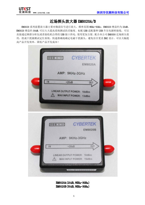
近场探头放大器EM8020A/BEM8020系列前置放大器主要对微弱信号进行放大,频率范围9KHz-3GHz;EM8020增益约为20dB,EM8020增益约30dB,可以大大提高系统测试的灵敏度。
标配USB适配器和USB升压电源转接线,可以直接通过频谱分析仪或者接收机自带的USB接口供电,使用更加方便。
配合本公司EM8030近场探头使用,组成干扰源测试定位系统,快速准确地确定电磁干扰源头,避免盲目更改EMI设计,可以大幅提高产品开发效率,降低产品开发成本!EM8020A(20dB,9KHz-3GHz)EM8020B(30dB,9KHz-3GHz)一、特性型号EM8020A EM8020B 频率范围9KHz-3GHz典型增益20dB30dB平坦度幅频曲线(图1)(图2)最大线性输出功率10dB典型噪声系数@2GHz3dB4dB 最大输入功率13dBm15dBm工作电压DC12V输入输出接口SMA(母头)尺寸约72*52*8mm图1EM8020A典型幅频曲线图2EM8020B典型幅频曲线二、应用◆EMI干扰源定位测试系统◆小信号放大干扰源测试系统示意图:三、各部分名称3.1放大器本体3.2配件USB适配器:DC5V USB升压电源线:5V转12V转接头:SMA(公头)转N头(公头)四、使用步骤1)将前置放大器输出端口连接到频谱仪或者接收机2)连接前置放大器电源3)连接输入信号(确保输入信号功率没超过放大器最大输入功率)五、使用须知1)未知信号大小测量时,不能连接前置放大器!确认信号很微弱时,才能连接前置放大器。
EM8020A最大输入功率13dBm;EM8020B最大输入功率15dBm;超过该值可能会引起放大器损坏。
2)配合EM8030使用时,确保周围没有强磁场存在后,才能连接前置放大器六、产品清单名称数量放大器本体1个适配器USB5V(CK-605)1个USB升压电源转接线(CK-615)1个SMA(公头转N公头)1个说明书1册保修卡1页检测报告1页。
《EMI接收机介绍》课件

调整接收机的频率、 增益、带宽等参数, 使其达到最佳接收 状态
定期检查接收机的 天线、电缆等硬件 设备,确保其正常 工作
定期进行接收机的 软件升级和维护, 确保其功能正常
维护保养
清洁保养:定期清洁接收机 的内部和外部,保持清洁
更换零件:定期更换接收机 的易损件,如天线、电池等
定期检查:检查接收机的各 个部件是否正常工作
EMI接收机介绍
目录
单击此处添加文本 EMI接收机概述 EMI接收机的组成 EMI接收机的性能指标 EMI接收机的调试与维护 EMI接收机的发展趋势
EMI接收机的定义和作用
定义:EMI接收 机是一种用于 接收和测量电 磁干扰(EMI)
的设备
作用:EMI接收 机可以帮助工程 师识别和定位电 磁干扰源,以便 采取措施减少或
信号输入部分
放大器:放大微弱信号
混频器:将信号转换为中频 信号
滤波器:滤除不需要的频率 信号
检波器:将中频信号转换为 直流信号
天线:接收电磁波信号
解调器:将直流信号转换为 音频信号
滤波部分
低通滤波器: 用于去除高频
噪声
高通滤波器: 用于去除低频
噪声
带通滤波器: 用于去除特定 频率范围内的
噪声
带阻滤波器: 用于去除特定 频率范围内的
灵敏度与接收机性能的关系:灵敏度 越高,接收机性能越好,能够接收更 微弱的信号,提高接收范围和信号质 量。
选择性
定义:接收机对不同频率信号的选择能力 重要性:直接影响接收机的性能和稳定性 指标:选择性越高,接收机的性能越好 影响因素:滤波器、天线、接收机设计等
抗干扰能力
抗干扰能力:EMI接收机的重要性能指标之一 干扰源:电磁干扰、射频干扰、噪声干扰等 抗干扰技术:滤波器、屏蔽、隔离等 抗干扰效果:提高接收机的稳定性和可靠性,降低误码率
EMI接收机(9kHz-300MHz)

参数
频率
频率范围
9kHz-300MHz
频率分辨率
1Hz
精度
2x10⁻⁶
测量时间
手动模式
2ms到90分钟
扫频模式
2ms到1s
分辨率带宽
数字EMI滤波器带宽
200Hz,9kHz,120kHz(-6dB)
硬件滤波器带宽
15kHz,1MHz
预选器
固定和可调滤波器
9kHz-150kHz;150kHz-2MHz;2MHz-6MHz;6MHz-15MHz;15MHz-30MHz;30MHz-60MHz;60MHz-140MHz;140MHz-300MHz
2.0到1.0(衰减器=0dB);
1.2到1.0(衰减器≥10dB)
跟踪信号发生器
频率范围
9kHz-30MHz
电平
50-95dBµV
其他参数
接口
以太网10/100BaeT,TCP端口1893
供电电源
230VAC±10% 50-60Hz,功率消耗50VA
工作温度
0℃-45℃
存储温度
-20℃-70℃
尺寸(WxHxD)
最大输入电平
DC电压
50V(AC耦合)
连续波RF功率
+20dBm
脉冲频谱密度
+97dBµV/MHz
本底噪声
检波器
IF 200Hz
IF 9kHz
IF 120kHz
峰值
<-10 dBµV
<10 dBµV
<10 dBµV
准峰值
<-15 dBµV
<5dBµV
<5dBµV
CISPБайду номын сангаас平均值
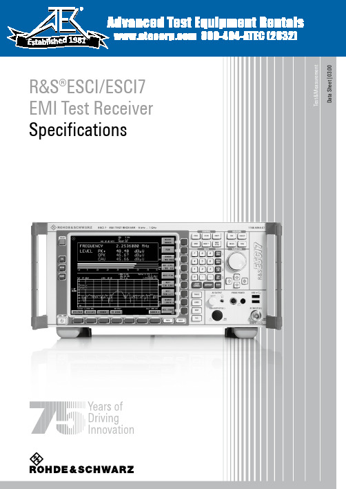
罗德·斯坦斯 EMI 测试接收器规格说明书
T e s t & M e a s u r e m e n tD a t a S h e e t | 03.00R&S®ESCI/ESCI7 EMI Test Receiver Specifications 800-404-ATEC (2832)e d 1981Version 03.00, June 20092 Rohde & Schwarz R&S ®ESCI/ESCI7 EMI Test ReceiverSpecificationsSpecifications apply under the following conditions: 15 minutes warm-up time at ambient temperature, specified environmentalconditions met, calibration cycle adhered to, and all internal automatic adjustments performed. Data without tolerances: typical values only. Data designated 'nominal' applies to design parameters and is not assured by Rohde & Schwarz.FrequencyR&S ®ESCIDC, AC coupled 9 kHz to 3 GHz R&S ®ESCI7 DC coupled 9 kHz to 7 GHz Frequency rangeAC coupled 1 MHz to 7 GHzResolution0.01 Hz Internal reference frequency (nominal) standardAging per year after 30 days of continuous operation 1 × 10⁻⁶Temperature drift +5 °C to +45 °C 1 × 10⁻⁶Internal reference frequency (nominal) R&S ®FSP-B4 option (OCXO)Aging per year after 30 days of continuous operation 1 × 10⁻⁷Temperature drift +5 °C to +45 °C 1 × 10⁻⁸External reference frequency 10 MHz Frequency display (receiver mode) numeric display Resolution 0.1 Hz Frequency display (analyzer mode)with marker or frequency counter Marker resolution span/500 Max. deviation sweep time > 3 × auto sweep time ±(marker frequency × reference frequencyerror + 0.5 % × span + 10 % × resolution bandwidth + ½ (last digit))Frequency counter resolution selectable 0.1 Hz to 10 kHz Count accuracy S/N > 25 dB ± (marker frequency × referencefrequency error + ½ (last digit))Display range of frequency axis R&S ®ESCI 0 Hz, 10 Hz to 3 GHzR&S ®ESCI7 0 Hz, 10 Hz to 7 GHz Max. deviation of display range 0.1 % f = 500 MHz, for f > 500 MHz see diagram100 Hz < –84 dBc (1 Hz), typ. –90 dBc (1 Hz) 1 kHz < –100 dBc (1 Hz), typ. –108 dBc (1 Hz) 10 kHz < –106 dBc (1 Hz), typ. –113 dBc (1 Hz) 100 kHz, span > 100 kHz < –110 dBc (1 Hz), typ. –113 dBc (1 Hz) 1 MHz, span > 100 kHz < –120 dBc (1 Hz), typ. –125 dBc (1 Hz) Spectral purity, SSB phase noise 10 MHz typ. –145 dBc (1 Hz)Residual FM f = 500 MHz, RBW = 1 kHz, sweep time = 100 mstyp. 3 HzVersion 03.00, June 2009Rohde & Schwarz R&S ®ESCI/ESCI7 EMI Test Receiver 3Scan (receiver mode)Scanscan of max. 10 subranges with different, independent settings Measurement time per frequencyselectable33 μs to 100 sSweep (analyzer mode)in time domain, span = 0 Hz 1 μs to 16000 sresolution 125 ns Sweep timein frequency domain, span ≥ 10 Hz 2.5 ms to 16000 s Max. deviation of sweep time1 %Resolution bandwidthsSweep filters3 dB bandwidths10 Hz to 3 MHz, in steps of 1/3/10 ≤ 100 kHz< 3 % Bandwidth accuracy 300 kHz to 3 MHz < 10 % ≤ 100 kHz< 5 Shape factor 60 dB:3 dB 300 kHz to 3 MHz < 156 dB bandwidths 200 Hz, 9 kHz, 120 kHz EMI bandwidths pulse bandwidth 1 MHz ≤ 120 kHz < 3 % Bandwidth accuracy 1 MHz < 10 % ≤ 120 kHz < 5 Shape factor 60 dB:6 dB 1 MHz< 15Video bandwidths analyzer mode1 Hz to 10 MHz, in steps of 1/3/10FFT filtersanalyzer mode 3 dB bandwidths 1 Hz to 30 kHz, in steps of 1/3/10 Bandwidth accuracy 5 %, nominal Shape factor 60 dB:3 dB2.5, nominalChannel filtersBandwidths100/200/300/500 Hz; 1/1.5/2/2.4/2.7/3/3.4/4/4.5/5/6/8.5/9/10/ 12.5/14/15/16/18 (RRC)/20/21/24.3 (RRC)/ 25/30/50/100/150/192/200/300/500 kHz 1/1.228/1.28 (RRC)/1.5/2/3/3.84 (RRC)/ 4.096 (RRC)/ 5 MHz(RRC = root raised cosine)PreselectionPreselectioncan be switched off in analyzer mode R&S ®ESCI: 11 preselection filtersR&S ®ESCI7: 12 preselection filters Bandwidths (–6 dB), nominal R&S ®ESCI, R&S ®ESCI7 < 150 kHz230 kHz, fixed-tuned lowpass filter 150 kHz to 2 MHz 2.6 MHz, fixed-tuned bandpass filter 2 MHz to 8 MHz 2 MHz, tracking bandpass filter 8 MHz to 30 MHz 6 MHz, tracking bandpass filter 30 MHz to 70 MHz 15 MHz, tracking bandpass filter 70 MHz to 150 MHz 30 MHz, tracking bandpass filter 150 MHz to 300 MHz 60 MHz, tracking bandpass filter 300 MHz to 600 MHz 80 MHz, tracking bandpass filter 600 MHz to 1 GHz 100 MHz, tracking bandpass filter 1 GHz to 2 GHz tracking highpass filter2 GHz to3 GHz fixed-tuned highpass filter R&S ®ESCI73 GHz to 7 GHztracking bandpass filter Preamplifier switchable, between preselection and 1st mixer20 dBVersion 03.00, June 20094 Rohde & Schwarz R&S ®ESCI/ESCI7 EMI Test ReceiverLevelDisplay rangedisplayed average noise level (DANL) to 30 dBmMaximum input level DC-coupled 0 V DC voltage AC-coupled 50 V RF attenuation 0 dB 20 dBm CW RF power RF attenuation ≥ 10 dB 30 dBm Pulse spectral density RF attenuation 0 dB 97 dB μV/MHz Max. pulse voltage RF attenuation ≥ 10 dB, 10 μs 150 VR&S ®ESCIRF attenuation ≥ 10 dB, 20 μs 10 mWs R&S ®ESCI7Max. pulse energyRF attenuation ≥ 10 dB, 10 μs 1 mWs Intermodulation1 dB compression of input mixer f > 200 MHz, RF attenuation 0 dB, preselection and preamplifier off5 dBm, nominal RF attenuation 0 dB, level 2 × –30 dBm, ∆f > 5 × RBW or 10 kHz, whichever is larger without preselection, without preamplifierR&S ®ESCI, R&S ®ESCI7 20 MHz to 200 MHz > 5 dBm 200 MHz to 3 GHz > 7 dBm, typ. 10 dBm R&S ®ESCI73 GHz to 7 GHz > 10 dBm, typ. 15 dBm with preselection, without preamplifierR&S ®ESCI, R&S ®ESCI7 20 MHz to 200 MHz > 0 dBm 200 MHz to 3 GHz > 2 dBm, typ. 5 dBm R&S ®ESCI73 GHz to 7 GHz > 10 dBm, typ. 15 dBm with preselection, with preamplifierR&S ®ESCI, R&S ®ESCI7 20 MHz to 200 MHz > –20 dBm 200 MHz to 3 GHz > –18 dBm, typ. –15 dBm R&S ®ESCI7Third-order intercept (TOI)3 GHz to 7 GHz > –10 dBm, typ. –5 dBmRF attenuation 0 dB, level –10 dBm, without preselection, without preamplifierR&S ®ESCI, R&S ®ESCI7 < 100 MHz typ. 25 dBm 100 MHz to 1.5 GHz typ. 35 dBm R&S ®ESCI71.5 GHz to 3.5 GHz typ. 70 dBmRF attenuation 0 dB, level –15 dBm, with preselection, without preamplifierR&S ®ESCI, R&S ®ESCI7 4 MHz to 100 MHz > 40 dBm 100 MHz to 1.5 GHz > 50 dBm R&S ®ESCI71.5 GHz to 3.5 GHz typ. 70 dBmRF attenuation 0 dB, level –35 dBm, with preselection, with preamplifierR&S ®ESCI, R&S ®ESCI7 4 MHz to 100 MHz > 25 dBm 100 MHz to 1.5 GHz > 35 dBm R&S ®ESCI7Second harmonic intercept (SHI)1.5 GHz to 3.5 GHz typ. 10 dBmVersion 03.00, June 2009Rohde & Schwarz R&S ®ESCI/ESCI7 EMI Test Receiver 5RF attenuation 0 dB, RBW = 10 Hz,VBW = 1 Hz, span = 0 Hz, trace average function over 20 sweeps, 50 Ω termination without preselection, without preamplifier, AC-coupledR&S ®ESCI 9 kHz < –105 dBm, nominal 100 kHz < –110 dBm, nominal 1 MHz < –130 dBm, nominal 10 MHz to 1 GHz < –142 dBm, typ. –145 dBm 1 GHz to 2.5 GHz < –140 dBm, typ. –143 dBm 2.5 GHz to 3 GHz < –138 dBm, typ. –141 dBm R&S ®ESCI7 1 MHz < –128 dBm, nominal 10 MHz to 1 GHz < –140 dBm, typ. –143 dBm 1 GHz to 2.5 GHz < –138 dBm, typ. –141 dBm 2.5 GHz to 3 GHz < –136 dBm, typ. –139 dBm 3 GHz to 7 GHz < –138 dBm, typ. –141 dBm without preselection, without preamplifier, DC-coupledR&S ®ESCI 9 kHz < –115 dBm 100 kHz < –120 dBm 1 MHz < –140 dBm, typ. –143 dBm 10 MHz to 1 GHz < –142 dBm, typ. –145 dBm 1 GHz to 2.5 GHz < –140 dBm, typ. –143 dBm 2.5 GHz to 3 GHz < –138 dBm, typ. –141 dBm R&S ®ESCI7 9 kHz < –115 dBm 100 kHz < –120 dBm 1 MHz < –138 dBm, typ. –141 dBm 10 MHz to 1 GHz < –140 dBm, typ. –143 dBm 1 GHz to 2.5 GHz < –138 dBm, typ. –141 dBm 2.5 GHz to 3 GHz < –136 dBm, typ. –139 dBm 3 GHz to 7 GHz < –138 dBm, typ. –141 dBm with preselection, without preamplifier, DC-coupledR&S ®ESCI 9 kHz < –115 dBm 100 kHz < –120 dBm, typ. –140 dBm 1 MHz < –140 dBm, typ. –148 dBm 10 MHz to 1 GHz < –142 dBm, typ. –150 dBm 1 GHz to 2.5 GHz < –140 dBm, typ. –148 dBm 2.5 GHz to 3 GHz < –138 dBm, typ. –141 dBm R&S ®ESCI7 9 kHz < –115 dBm 100 kHz < –120 dBm, typ. –140 dBm 1 MHz < –138 dBm, typ. –146 dBm 10 MHz to 1 GHz < –140 dBm, typ. –148 dBm 1 GHz to 2.5 GHz < –138 dBm, typ. –146 dBm 2.5 GHz to 3 GHz < –136 dBm, typ. –139 dBm 3 GHz to 7 GHz < –138 dBm, typ. –141 dBm with preselection, with preamplifier, DC-coupledR&S ®ESCI 9 kHz < –135 dBm 100 kHz < –140 dBm 1 MHz < –150 dBm, typ. –153 dBm 10 MHz to 1 GHz < –152 dBm, typ. –155 dBm Displayed average noise level (DANL) (analyzer mode)1 GHz to 3 GHz < –150 dBm, typ. –153 dBm R&S ®ESCI7 9 kHz < –135 dBm 100 kHz < –140 dBm 1 MHz < –148 dBm, typ. –151 dBm 10 MHz to 1 GHz < –150 dBm, typ. –153 dBm1 GHz to 7 GHz < –148 dBm, typ. –151 dBmVersion 03.00, June 2009 6 Rohde & Schwarz R&S ®ESCI/ESCI7 EMI Test ReceiverNoise indication (receiver mode) Nominal, calculated from DANL data, 0 dB RF attenuation, 50 Ω termination without preamplifierR&S ®ESCI, R&S ®ESCI7 9 kHz, BW = 200 Hz < 5 dB μV 150 kHz, BW = 200 Hz < 0 dB μV 150 kHz, BW = 9 kHz < 16 dB μV 1 MHz, BW = 9 kHz < –4 dB μV 10 MHz to 30 MHz, BW = 9 kHz < –6 dB μV 30 MHz to 1 GHz, BW = 120 kHz < 6 dB μV 1 GHz to 3 GHz, BW = 1 MHz < 16 dB μV R&S ®ESCI73 GHz to 7 GHz, BW = 1 MHz < 20 dB μV with preamplifierR&S ®ESCI, R&S ®ESCI7 9 kHz, BW = 200 Hz < –15 dB μV 150 kHz, BW = 200 Hz < –20 dB μV 150 kHz, BW = 9 kHz < –4 dB μV 1 MHz, BW = 9 kHz < –14 dB μV 10 MHz to 30 MHz, BW = 9 kHz < –16 dB μV 30 MHz to 1 GHz, BW = 120 kHz < –4 dB μV 1 GHz to 3 GHz, BW = 1 MHz < 6 dB μV R&S ®ESCI7Average (AV) display3 GHz to 7 GHz, BW = 1 MHz < 3 dB μV max peak typ. +11 dB RMS typ. +1 dB quasi-peak band A typ. +3 dB band B typ. +4 dB Increase of DANL relative to AV displaybands C and D typ. +6 dB Immunity to interference Image frequency> 70 dB Intermediate frequency> 70 dB Spurious response f > 1 MHz, 0 dB RF attenuation, without input signal< –103 dBmOther interfering signals ∆f > 100 kHz, mixer level < –10 dBm< –70 dBcRF shielding field strength 3 V/m, 0 dB RF attenuation, 50 Ω termination, f ≠ f IFlevel indication < 10 dB μV, nominalLevel display (receiver mode) digital numeric, resolution 0.01 dB Level displayanalog bargraph display separate for eachdetectorlevel axis 10 dB to 200 dB in steps of 10 dB Spectrum frequency axis linear or logarithmic selectable DetectorsThree detectors can be switched on simultaneously. average (AV), RMS, max peak, min peak, quasi-peak (QPK), CISPR-AV, CISPR-RMS Units of level display dB μV, dBm, dB μA, dBpW, dBpT Measurement timeselectable 33 μs to 100 s Level display (analyzer mode) Screen501 × 400 pixels(one measurement diagram); max. two measurement diagrams with independent settingsLogarithmic level display range 1 dB, 10 dB to 200 dB in steps of 10 dB Linear level display range10 % of reference level per level division, 10 divisions one measurement diagram 3 Number of traces two measurement diagrams 6Trace detectorsmax peak, min peak, auto peak, sample, quasi-peak, average, RMSTrace functionsclear/write, max hold, min hold, average default value 501Number of measurement pointsrange125 to 8001 in steps of approx. a factor of 2Version 03.00, June 2009Rohde & Schwarz R&S ®ESCI/ESCI7 EMI Test Receiver 7logarithmic level display –130 dBm to 30 dBm in steps of 0.1 dB Setting range of reference level linear level display70.71 nV to 7.07 V in steps of 1 % logarithmic level display dBm, dBmV, dB μV, dB μA, dBpW Units of level axislinear level displaymV, μV, mA, μA, nW, pWMax. uncertainty of level measurement level = –30 dBm, RF attenuation 10 dB, RBW 10 kHz, reference level –25 dBm without preselection/preamplifier <0.2 dB (σ = 0.07 dB) Reference level uncertainty at 128 MHzwith preselection/preamplifier <0.3 dB (σ = 0.1 dB) without preselection/preamplifier, AC-coupledR&S ®ESCI9 kHz to 50 kHz < +0.5 dB/–1 dB, nominal 50 kHz to 3 GHz < 0.5 dB (σ = 0.17 dB) R&S ®ESCI71 MHz to 3 GHz < 0.5 dB (σ = 0.17 dB) 3 GHz to 7 GHz <2 dB (σ = 0.7 dB) without preselection/preamplifier, DC-coupledR&S ®ESCI9 kHz to 3 GHz < 0.5 dB (σ = 0.17 dB) R&S ®ESCI79 kHz to 3 GHz < 0.5 dB (σ = 0.17 dB) 3 GHz to 7 GHz < 2 dB (σ = 0.7 dB) with preselection/preamplifier, AC-coupledR&S ®ESCI9 kHz to 50 kHz < +0.8 dB/–1.3 dB, nominal 50 kHz to 3 GHz < 0.8 dB (σ = 0.27 dB) R&S ®ESCI71 MHz to 3 GHz < 0.8 dB (σ = 0.27 dB) 3 GHz to 7 GHz <2 dB (σ = 0.7 dB) with preselection/preamplifier, DC-coupledR&S ®ESCI9 kHz to 3 GHz < 0.8 dB (σ = 0.27 dB) R&S ®ESCI79 kHz to 3 GHz < 0.8 dB (σ = 0.27 dB) Frequency response referenced to 128 MHz3 GHz to 7 GHz < 2 dB (σ = 0.7 dB)Uncertainty of attenuator settingf = 128 MHz,0 dB to 70 dB, referenced to 10 dB RF attenuation < 0.2 dB (σ = 0.07 dB) Uncertainty of reference level setting < 0.2 dB (σ = 0.07 dB) S/N > 16 dBRBW ≤ 120 kHz 0 dB to –70 dB < 0.2 dB (σ = 0.07 dB) –70 dB to –90 dB < 0.5 dB (σ = 0.17 dB) RBW > 120 kHz 0 dB to –50 dB < 0.2 dB (σ = 0.07 dB) Log/lin display nonlinearity–50 dB to –70 dB < 0.5 dB (σ = 0.17 dB) referenced to RBW = 10 kHz 10 kHz to 120 kHz < 0.1 dB (σ = 0.03 dB) 300 kHz to 10 MHz < 0.2 dB (σ = 0.07 dB) Bandwidth switching uncertaintyFFT filter, 1 Hz to 3 kHz < 0.2 dB (σ = 0.07 dB)Total measurement uncertainty (95 % confidence level) Signal level 0 dB to –70 dB below reference level, S/N > 20 dB, RBW ≤ 120 kHz, DC-coupledwithout preselection/preamplifier < 3 GHz 0.5 dB 3 GHz to 7 GHz 1.5 dB with preselection/preamplifier < 3 GHz 1 dB3 GHz to 7 GHz 1.5 dB Quasi-peak indication in line with CISPR 16-1-1Version 03.00, June 20098 Rohde & Schwarz R&S ®ESCI/ESCI7 EMI Test ReceiverTrigger functionsTriggerTrigger sourcefree run, video, external, IF levelspan ≥ 10 Hz 125 ns to 100 s, resolution min. 125 ns (or 1 % of offset)Trigger offsetspan = 0 Hz±(125 ns to 100 s), resolution min. 125 ns, dependent on sweep timeMax. deviation of trigger offset±(125 ns + (0.1 % × trigger offset))Gated sweep Gate source video, external, IF level Gate delay 1 μs to 100 sGate length125 ns to 100 s, resolution min. 125 ns (or 1 % of gate length)Max. deviation of gate length± (125 ns + (0.1 % × gate length))Audio demodulationAF demodulation modes AM and FMAudio outputloudspeaker and earphone jack Marker hold time in analyzer modeselectable100 ms to 60 sInputs and outputs (front panel)RF inputImpedance 50 ΩConnector N femaleRF attenuation < 10 dB, DC-coupledR&S ®ESCI, R&S ®ESCI7 9 kHz to 1 GHz < 2.0, typ. 1.5 1 GHz to 3 GHz < 3.0, typ. 2.5 R&S ®ESCI73 GHz to 7 GHz< 3.0, typ. 2.5RF attenuation ≥ 10 dB, DC-coupledR&S ®ESCI, R&S ®ESCI7 9 kHz to 1 GHz < 1.2 1 GHz to 3 GHz < 1.5 R&S ®ESCI73 GHz to 7 GHz< 2.0RF attenuation < 10 dB, AC-coupledR&S ®ESCI9 kHz to 100 kHz 2.5 100 kHz to 1 GHz 2.0 1 GHz to 3 GHz 3.0 R&S ®ESCI71 MHz to 5 MHz 2.5 5 MHz to 1 GHz 2.0 1 GHz to 7 GHz3.0RF attenuation ≥ 10 dB, AC-coupledR&S ®ESCI9 kHz to 100 kHz typ. 2.5 100 kHz to 1 GHz < 1.2 1 GHz to 3 GHz < 1.5R&S ®ESCI71 MHz to 5 MHz typ. 2.5 5 MHz to 1 GHz < 1.2 1 GHz to3 GHz < 1.5 VSWR 3 GHz to 7 GHz< 2.0Setting range of attenuator 0 dB to 70 dB in steps of 5 dBProbe power supply Supply voltages+15 V DC, –12.6 V DC and ground, max. 150 mA, nominalVersion 03.00, June 2009Rohde & Schwarz R&S ®ESCI/ESCI7 EMI Test Receiver 9Power supply for antennas, etc. Supply voltages±10 V DC and ground, max. 100 mA, nominalUSB interface2 ports, type A plug, version 2.0AF output Connector3.5 mm jackImpedance 10 ΩOpen-circuit voltageadjustable up to 1.5 VInputs and outputs (rear panel)IF 20.4 MHz Connector BNC female Impedance50 Ωmixer level > –60 dBm RBW ≤ 100 kHz or FFT –10 dBm at reference level LevelRBW > 100 kHz0 dBm at reference levelReference frequency outputConnector BNC female Impedance 50 Ω Output frequency 10 MHzLevel 0 dBm, nominalReference frequency inputConnector BNC female Input frequency 10 MHzRequired level 0 dBm from 50 ΩPower supply for noise sourceConnector BNC female Output voltage switchable 28 V, nominalExternal trigger/gate inputConnector BNC female Impedance > 10 k Ω Trigger voltage 1.4 V (TTL)IEC/IEEE bus remote control interface in line with IEC 625-2 (IEEE 488.2)Connector 24-pin Amphenol female Command set SCPI 1997.0Interface functionsSH1, AH1, T6, SR1, RL1, PP1, DC1, DT1, C0Serial interfaceRS-232-C (COM), 9-pin D-SubPrinter interfaceparallel (Centronics compatible)upper connector type A plug, version 1.1 USB interface lower connectortype A plug, version 2.0External monitor (VGA) ConnectorVGA-compatible, 15-pin D-SubUser interface 25-pin D-SubVersion 03.00, June 200910 Rohde & Schwarz R&S ®ESCI/ESCI7 EMI Test ReceiverGeneral dataDisplay 21 cm TFT color display Resolution 640 × 480 pixel (VGA)Pixel error rate< 2 × 10⁻⁵Mass memory1.44 Mbyte 3½'' disk drive, hard disk Data storage R&S ®ESCI only> 500 instrument setups and tracesTemperature ranges+5 °C to + 40 °C Operating temperature range with R&S ®ESCI-B20 option 0 °C to +50 °C+5 °C to + 45 °C Permissible temperature range with R&S ®ESCI-B20 option 0 °C to +55 °C Storage temperature range –40 °C to +70 °CClimatic loading+40 °C at 95 % relative humidity (EN 60068-2-30)Mechanical resistance Sinusoidal vibration0.5 g from 5 Hz to 150 Hz, max. 2 g at 55 Hz,in line with EN 60068-2-6, EN 61010-1, MIL-T-28800D, class 510 Hz to 100 Hz, acceleration 1 g (rms) Random vibration with R&S ®ESCI-B20 option 10 Hz to 300 Hz, acceleration 1.9 g (rms) Shock40 g shock spectrum,in line with MIL-STD-810C and MIL-T-28800D, classes 3 and 5operation with external reference 2 years Recommended calibration interval operation with internal reference1 yearPower supply AC supply100 V to 240 V AC, 50 Hz to 400 Hz, 3.1 A to 1.3 A,class of protection I in line with VDE 411 Power consumption typ. 70 VASafety in line with EN 61010-1, UL 3111-1, CSA C22.2 No. 1010-1, IEC 1010-1 EMCEMC Directive 2004/108/EC including:EN 61326 class B (emission),CISPR 11/EN 55011 group 1 class B (emission)EN 61326 table A.1 (immunity, industrial)Test marksVDE, GS, CSA, CSA-NRTL/CDimensions and weight DimensionsW × H × D 412 mm × 197 mm × 417 mm (16.22 in × 7.76 in × 16.42 in) R&S ®ESCI10.5 kg (23.15 lb) Weight without options R&S ®ESCI712.4 kg (27.34 lb)Version 03.00, June 2009Rohde & Schwarz R&S ®ESCI/ESCI7 EMI Test Receiver 11Ordering informationDesignation Type Order No.EMI Test Receiver 9 kHz to 3 GHz R&S ®ESCI 1166.5950.03EMI Test Receiver 9 kHz to 7 GHz R&S ®ESCI7 1166.5950.07 Accessories suppliedPower cable, operating manual, service manualOptionsDesignation Type Order No.Rugged Case, with carrying handle R&S ®FSP-B1 1129.7998.02OCXO Reference Frequency R&S ®FSP-B4 1129.6740.02TV Trigger/RF Power Trigger R&S ®FSP-B6 1129.8594.02Internal Tracking Generator, I/Q Modulator R&S ®FSP-B9 1129.6991.02External Generator Control R&S ®FSP-B10 1129.7246.03LAN Interface 100BaseT R&S ®FSP-B16 1129.8042.03Expanded Environmental Specifications R&S ®ESCI-B20 1155.1606.14DC Power Supply R&S ®FSP-B30 1155.1158.02Battery Pack R&S ®FSP-B31 1155.1258.02Spare Battery Pack R&S ®FSP-B32 1155.1506.02Service OptionsDesignation Type Order No.R&S ®ESCIOne-Year Repair Service following the warranty periodR&S ®RO2ESCI 1166.5950.S16 Two-Year Repair Service following the warranty periodR&S ®RO3ESCI 1166.5950.S12 Four-Year Repair Service following the warranty periodR&S ®RO5ESCI 1166.5950.S14 Two-Year Calibration Service R&S ®CO2ESCI 1166.5950.S15Three-Year Calibration Service R&S ®CO3ESCI 1166.5950.S11Five-Year Calibration Service R&S ®CO5ESCI 1166.5950.S13R&S ®ESCI7One-Year Repair Service following the warranty periodR&S ®RO2ESCI7 1166.5950.S26 Two-Year Repair Service following the warranty periodR&S ®RO3ESCI7 1166.5950.S22 Four-Year Repair Service following the warranty periodR&S ®RO5ESCI7 1166.5950.S24 Two-Year Calibration Service R&S ®CO2ESCI7 1166.5950.S25Three-Year Calibration Service R&S ®CO3ESCI7 1166.5950.S21Five-Year Calibration Service R&S ®CO5ESCI7 1166.5950.S23For product brochure, see:• PD 0758.1558.12 (ESCI) • PD 5214.2762.12 (ESCI7)and About Rohde & SchwarzRohde & Schwarz is an independent group of companies specializing in electronics. It is a leading supplier of solu-tions in the fields of test and measurement, broadcasting, radiomonitoring and radiolocation, as well as secure com-munications. Established 75 years ago, Rohde & Schwarz has a global presence and a dedicated service network in over 70 countries. Company headquarters are in Munich, Germany.Regional contactEurope, Africa, Middle East+49 1805 12 42 42* or +49 89 4129 137 74 *********************************North America1888TESTRSA(188****8772)**********************************.com Latin America +1 410 910 79 88************************************Asia/Pacific+65 65 13 04 88**************************************Rohde & Schwarz GmbH & Co. KG Mühldorfstraße 15 | 81671 MünchenPhone +49 89 41 290 | Fax +49 89 41 29 121 R&S® is a registered trademark of Rohde & Schwarz GmbH & Co. KG Trade names are trademarks of the owners | Printed in Germany (sv) PD 0758.1558.22 | Version 03.00 | June 2009 | R&S®ESCI/ESCI7 Subject to change*0.14 €/min within German wireline network; rates may vary in othern etworks (wireline and mobile) and countries. Certified Environmental SystemISO 14001Certified Quality SystemISO 9001。
EM5080B与R品牌接收机辐射(EMI)测试曲线对比案例2019.0515

EM5080B 与R*品牌接收机辐射(EMI)测试曲线对比案例参考标准:GB9254:EN550323mClass B(QP)信息技术设备的无线电骚扰限值和测量方法测量设备选型:设备名称规格图片备注接收机1频率:EM5080B:9kHz-1GHz精度:≤1.5dB EM5080B 为时域接收机,扫描速度非常快,传导测量可在2.5s 内完成。
接收机2R*品牌:9KHz-3.6GHz 认证级接收机对数周期天线Schwarzberck VULB916330MHz-3GHz电波暗室3米法半电波暗室(9*6*6)概述:辐射干扰(EMI)是指干扰源通过空间把其信号耦合(干扰)到另一个电网络,能发射电磁波并影响其他系统或本系统内其他子系统的正常工作。
使用Schwarzberck对数天线检测出设置在电波屏蔽室内的试验品的辐射信号,通过EMI接收机来测量频率与强度,通过相关标准判定是否符合要求。
以下测试产品为客户的DC-DC电源,下面使用R*品牌的接收机与知用的EM5080B接收机测试。
(产品输入是DC75V,输出是12V10A)客户测试辐射DCDC电源①下图是在深圳市坪山金XX(标准第三方认证实验室)电波暗室内,对产品测试水平、垂直辐射测试布置环境图。
天线水平辐射测试布置图天线垂直辐射测试布置图下图为使用R*品牌接收机和Schwarzberck VULB916330MHz-3GHz的对数天线测试产品的水平、垂直辐射曲线图。
ESPI水平辐射测试曲线图ESPI垂直辐射测试曲线图ESPI水平、垂直辐射测试报告图②下图为使用深圳知用接收机EM5080B和Schwarzberck VULB916330MHz-3GHz的对数天线,测试产品的水平、垂直辐射曲线图。
知用EM5080B水平辐射测试曲线图用EM5080B垂直辐射测试曲线图结论:从上面①和②测试曲线图中对比知道,在相同的实验环境下,使用深圳知用的EMI接收机测试的辐射曲线与R*品牌的接收机测试出来的辐射曲线在水平,垂直两个方向测试出来的形状趋势和数据上是十分接近的,EM5080B完全可以满足辐射干扰预测试测量。
知用测试探头近场探头EM5030 EM5030LF概述
1.概述
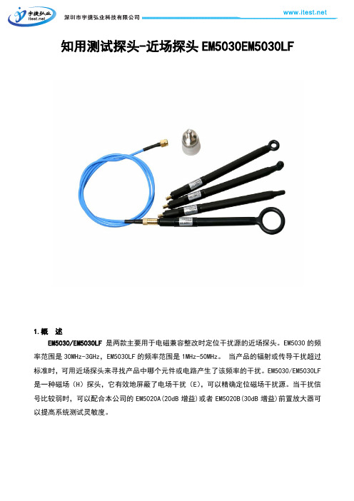
EM5030/EM5030LF 是两款主要用于电磁兼容整改时定位干扰源的近场探头。
EM5030的频率范围是30MHz-3GHz,EM5030LF的频率范围是1MHz-50MHz。
当产品的辐射或传导干扰超过标准时,可用近场探头来寻找产品中哪个元件或电路产生了该频率的干扰。
EM5030/EM5030LF 是一种磁场(H)探头,它有效地屏蔽了电场干扰(E),可以精确定位磁场干扰源。
当干扰信号比较弱时,可以配合本公司的EM5020A(20dB增益)或者EM5020B(30dB增益)前置放大器可
以提高系统测试灵敏度。
EM5030-1 EM5030-2 EM5030-3 EM5030-4 EM5030LF-5
EM5030LF-6 3.应 用
■ EMI 辐射干扰源定位 ■ EMI 传导干扰源定位 ■ 电磁场强度检测
使用示意图:
4. 产品描述
◆ EM5030
EM5030-1 EM5030-2
EM5030-3 EM5030-4
标配输出线:约1m 标配转接头:SMA母头转N公头 EM5030LF
EM5030LF-5 EM5030LF-6
标配输出线:约1m 标配转接头:SMA母头转N公头。
- 1、下载文档前请自行甄别文档内容的完整性,平台不提供额外的编辑、内容补充、找答案等附加服务。
- 2、"仅部分预览"的文档,不可在线预览部分如存在完整性等问题,可反馈申请退款(可完整预览的文档不适用该条件!)。
- 3、如文档侵犯您的权益,请联系客服反馈,我们会尽快为您处理(人工客服工作时间:9:00-18:30)。
(9kHz-30MHz)
的EMI测试接收机;是基于微处理器控制的智能接收机,通过标配的计算机软件控制,实现自动测试,软件免费升级,方便客户使用;可实现传导发射限值测量;具有极高的性价比。
EM5080A完全符合CISPR 16-1标准,用于依据CISPR,EN550XX,FCC和MIL等标准的电磁干扰测量。
特别适合于针对家电(CISPR 14-1)、照明设备(CISPR 15)的EMI测试。
EM5080A接收机可切换到实时频谱分析模式,RBW为1.5kHz,极高的扫描速度,适用于各种整改测试。
2. 特性
◆CISPR 16-1-1标准全兼容准峰值检波器低至2Hz PRF(A波段),B波段低至10Hz
◆业界领先的软件无线电技术SDR (Software Defined Radio)构建平台, 高精度高稳定性◆高速高精度AD+FPGA; 全数字DDC变换; 全数字中频滤波器
◆全数字峰值、准峰值、CISPR 平均值
◆标配频谱分析模式,实时观察结果, 便于工程师快速进行EMI的整改
◆免费测试软件,基于Windows平台, 使用方便,用户可自行下载最新软件
◆选用近场探头EM5030,在设计调试阶段查找发射源以及泄漏
◆选用内置限幅器的人工电源网络EM5040A或共模差模分离的人工电源网络EM5040B, 完成
传导发射限值测量和分析
后面版:
1.射频输入口:50Ω,SMA female.
2.LED灯:电源指示灯,绿色。
B接口:USB2.0 数据通信接口,连接PC软件,实现EMI测量
4.电源接口:电源供电接口,DC 12V供电。
5.开关:按键开关,控制机器是否通电。
■附件说明
射频连接线(CK-318):BNC male转SMA male
电源适配器(CK-612) DC12V/1.2A
前保证仪器表面的干燥和清洁。
✧传导测量大功率设备时,为了避免意外损坏接收机,被测设备在开启和断开瞬
间,可以断开接收机的射频输入连接。
✧推荐使用隔离变压器,可以防止意外触电情况的发生。
✧如果产品出现问题,请及时与我公司联系。
请不要擅自打开外壳进行维修,以
免发生意外。
5.1传导测试平台搭建示意图
项目说明
1 至少2mx2m的金属板
2 被测设备(EUT)
3 供电线长度超过1m情况下的折叠方式
4 被测设备供电接口
5.2安装测试步骤
1. 把EM5040A和接收机EM5080A的地线连接起来,接地。
2. 连接隔离变压器EM5060和人工电源网络EM5040A。
3. 连接被测设备,参考以上示意图的位置摆放设备。
4. EM5040A的干扰信号输出端连接EMI接收机EM5080A输入端。
5. 根据被测产品标准选择EM5040A相应的滤波器。
6. EM5060隔离变压器连接电网,通电测量。
7. 使用过程中通过EM5040A按键开关选择不同的相线进行测试。
产品标配
名称数量
接收机本体1个
DC12V/1.2A适配器1个
SMA-BNC连接线1根
USB连接线(AM-BM,1.5米)1根
高档工具包1个
说明书1份
保修卡1个
检测报告1份。
