dido手环说明书
KADIO电子表说明书

KADIO电子表说明书S4 S1S3 S2使用方法:一般表示时、分、秒和星期。
✧按S1表示日期。
“START”✧按S2显示被设定好的闹铃时间。
“RESET”✧按S3菜单出现。
“MODE”✧按S4背景灯亮,适合夜间用。
“LIGHT”时间和日期的设定:在显示标准时刻的时候,按三次S3,秒调整,按S1秒为00。
按三次S3,按一次S2,分钟开始调整,用S1核对。
按三次S3,按两次S2,小时开始闪动,用S1调整小时的时间。
其中,按住S1不动,显示12小时形式和24小时形式的时间调整。
按三次S3,按三次S2,日期~~~~。
按三次S3,按四次S2,找到月份~~~~。
按三次S3,按五次S2,找到星期,然后按S1对星期进行调整。
想要恢复标准时间显示的时候,按S3,返回显示标准时刻。
定闹铃时间:按S3两回,闹铃的小时开始闪动,按S1调。
闹铃的开关:正常显示时刻的时候,按住S2同时按一下S1,闹铃的开关。
闹铃的一时停止:按S1,闹铃一时停止。
五分钟后再叫。
解除闹铃设置:正常显示状态下,按住S2,同时按一下S1,解除闹铃。
时间报时的设定:时报的标志,可以用按S2的方法确认。
按S2看到星期的七个格全部显示,表示有整点报时,星期的七个格全部不显示,表示没有整点报时。
标准时刻表示的时候,按住S2,同时按一下S3,看到星期的七个格全部显示,时报铃就被设定上了。
解除的时候,重复上面的操作就可以了。
精密时间测定器功能,因为不太用,这里就不记录了。
c7i手环说明书
c7i手环说明书
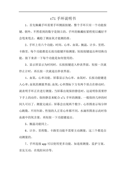
1、首先佩戴手环需要手环侧面按键,整个手环只有一个功能按键。
朝外,不然看到的数字是倒立的。
手环的佩戴松紧程度以戴好不会甩来甩去,戴稳了测血氧才能测的准。
2、手环上有六个功能:时间,心率,血氧,腕温,计步,里程,卡路里。
每个功能都是长按功能键开始测量,短按按键退出和切换功能。
接下来讲一下每个功能是如何使用的。
3、显示屏显示为时间时,长按按键进入秒表界面,短按一次就停止计时,再长按一次就退出秒表界面。
4、血氧,心率功能。
屏幕显示为心率,血氧时,长按功能键进入心率,血氧的测量界面,血氧,心率图标下方有两个原点在移动时,就表明手环正在进行测量。
当屏幕出现保持静息时,这说明你需要停下手上的动作,保持静息来配合c7i手环的测量。
一般保持几秒的时间久可以了。
测量完成后,屏幕会出现两个数字,心形图表示每分钟心跳数。
不同年龄、性别的人正常心率都不同,水滴形图表示此时你血液中的氧含量。
再短按一下功能键退出。
5、腕温功能同上。
6、计步、里程数、卡路里功能不需要主动测量,这三个都是自动测量的。
7、手环连接app可以使用更多功能。
如连续测量,监护方案,亲友互动,在线轻问诊等。
(完整word版)运动心率手环使用手册
运动心率手环使用手册感谢您使用我们的产品。
使用本手环前请先阅读本操作说明:1、警告:开始新的运动项目之前请咨询你的医生。
智慧手环尽管可以监测实时动态心率,但并不能用作任何医疗用途。
切记在开始任何运动和饮食计划前咨询医生。
2、设备要求:支持安卓4.3,IOS7.0 蓝牙4.0及以上版本。
3、充电:使用前请先通过5V500mA USB设备对手环进行充电,确保手环电量充足。
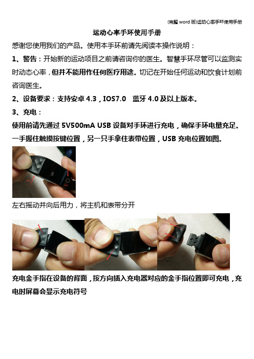
一手握住触摸按键位置,另一只手拿住表带位置,USB充电位置如图。
左右摇动并向后用力,将主机和表带分开充电金手指在设备的背面,按方向插入充电器对应的金手指位置即可充电,充电时屏幕会显示充电符号插入USB充电底座上(充电5V500MA),即可充电,充电时间约2小时。
为保证充电接触良好,请保证金属触点无脏污,氧化和杂质。
充电时屏幕显示充电符号。
如果设备长期不用,请务必保证每3个月补充电一次。
装机时,先装USB充电头到表带,再装另一头。
一、手环与手机APP连接1、开机:长按手环屏幕下方3秒开机,开机时手环会显示配对码,用于识别手环。
关机时间界面长按按键3秒进入二级菜单,点按切换到关机选项,长按进入关进选项,点按切换on为off,屏幕显示5 4 3 2 1关机。
复位二级菜单下选择复位图标,长按3秒进入复位选项,点按切换off为on,系统即复位,手环时间和数据恢复出厂设置。
2、安装app:手机扫描包装盒上面的二维码,或者在Google Play ,App store,应用宝商店搜索“智慧手环”下载APP.3、连接手环:手环靠近手机,打开并进入智慧手环APP,根据APP连接向导搜索蓝牙手环,完成配对连接,手环的蓝牙名称是“Smart Watch”。
点下一步完成连接。
苹果设备配对连接:苹果设备IOS系统第一次app连接好以后会提示蓝牙配对请求,请点“配对”连接,手环才能接收来自IOS系统推送的来电、短信、QQ、微信等通知提醒。
否则无法接收提醒。
4、删除手环:设备连接后如需删除设备,可在APP-设定--我的手环进行设备删除,如果是登录帐号绑定手环,需要在APP—设置—设备管理对设备进行解绑操作。
DayBand CA5058-manual.pdf℃℃智能心率血压手环使用说明书

℃℃智能心率血压手环iOS8.0Android4.4及以上初次使用请确保电量充足,若电量太低无法开机请充电满)关机充电会自动开机,开机状况下手环主界面电池条会呈流动状态。
※如果设备长期不用,请务必保证每3个月补充电一次。
界面触控按钮Ⅱ使用准备初次使用,请将手环取出,用对应的充电器对设备进行充电。
充电时,手环会自动开机,充电时长为2小时左右。
(充电方式如下图:将手环主体从腕带中取出,将充电端口插入标准的USB接口即Ⅲ充电方式Pull out the device from the strap, Using build-in USB charger to connect with power source for charging. Charge time is 2hours.How to charge运动模式:手环功能心率测量:量的数据。
(单次测量请等待25秒左右,因未贴近皮肤、测量处有污垢等原因,数值与实际数值可能有误差,数据不做医疗参考。
)距 离:睡眠监测:没有活动,或者心率变慢且平稳后,手环将自动开始进行睡眠监测,根据您的睡眠情况分析出深度睡眠及浅度睡眠时间。
卡路里数:短信提醒: 提示语言,信息可在手机上查看。
血压测量:量的数据。
(单次测量请等待25秒左右,因未贴近皮肤、测量处有污垢等原因,数值与实际数值可能有误差,数据不做医疗参考。
)* Please charge the device once per 3 months if put it idle no using.Method1: Scan the code to download the APP .ensure the bluetooth is on,and search “DayBand”.from Google Play market or App Store.After downloaded, Please enter into App to connect the watch throught BT.Connection Instruction Download the AppIOS 8.0 or aboveAndroid 4.4 or aboven” on the screen.Menu/Long-press power onto log out.connected with phone.Ⅷ1. Ca ① Pl above ② If it still unable to connect, enter the Authorization Management→ Application Al low turn on ③ Pl when full charged.2. Th powe In this case, the App is not bound with bracelet sucessfully, please try again.3. Ca Pull 使用说明书User ManualHow it chargeHow to wearWear the watch on the left hand,lose the backside sensor to the skin,Adjust the fitable size to wear,and press the clip button,insert the metal pin into the hole.1.请注意手环底部保持清洁和干净,不能有污渍和水,否则会影响测试。
云帝智能手环说明书

云帝智能手环说明书一、功能介绍1.健康监测:云帝智能手环内置多种传感器,能够实时监测心率、血压、血氧和睡眠质量等关键指标,帮助您全面了解自己的健康状况。
2.运动追踪:手环具备运动追踪功能,可以记录您的步数、距离、消耗的卡路里和运动时间等数据,帮助您更好地管理和改善自己的运动习惯。
4.闹钟提醒:手环内置闹钟功能,可以设置多个闹钟,提醒您按时起床、锻炼或执行其他重要事务。
5.防水设计:手环采用防水设计,配备防水等级IP68,可以在漂亮的天气和户外活动时正常使用,轻松满足您的日常需求。
二、使用方法2.佩戴手环:手环带有一个可调节的表带,将手环的显示屏朝外,将手环折叠并将手环带上手腕,将带子插入表扣,将手环固定在手腕上,确保佩戴舒适且紧密。
3.使用功能:打开手环的显示屏,通过滑动和点击屏幕进行操作。
您可以通过手环上的按钮或在APP上进行设置,开启或关闭各种功能,根据需要进行设置。
4.同步数据:云帝智能手环可以主动和手机进行数据同步。
当您打开APP时,手环上的数据将自动更新到APP上,同时您的手机上的数据也会同步到手环上。
三、注意事项1.充电问题:请使用原装充电器进行充电,不要用其他充电器充电,避免损坏设备。
充电时,请确保充电接口干燥和没有异物,避免电气短路。
2.水上使用:虽然手环具有防水设计,但请避免长时间浸泡在水中,如游泳、潜水等水下活动,以免损坏手环。
4.人机交互:在使用手环时,避免过度运动,以免影响手环的读数和用户的体验。
当手环上有消息提醒时,请及时查看手机上的具体内容。
总结:云帝智能手环是一款能够实现多项功能的智能设备,通过它,您可以追踪健康数据、管理运动情况、及时接收消息提醒等。
在使用过程中,请根据说明书操作,并注意手环的充电和使用注意事项,保持合理使用和保养,以延长手环的寿命,并为您的健康和生活带来更多的便利和乐趣。
AllPro DS 腕手系统说明书

AllPro DS FootProduct ManualThe AllPro DS foot system has been designed and manufactured for specific patient weights. Failure to follow the weight guidelines and/or overload conditions caused by the patient, such as heavy lifting, high impact sports, or abusive activities that would otherwise damage the natural limb, may void the warranty.• Please review the FAQ section of the manual on page 7 before use ofthe foot. These instructions should be read prior to fitting and followedto ensure the proper integration of the AllPro DS foot into the patient’s prosthetic system.• The foot stiffness is based on weight and activity level. Please provide accurate patient information so that the appropriate foot may be selected.• The AllPro DS foot’s integrated DuraShock is designed to be used with any standard pyramid receiver device.Product SpecificationsStandard build height: 8.75 and 10.75 in. (22.2 and 27.3 cm) Rated for patients up to 250 lbs. (113 kg)Weight: 25.6 oz. (720 g) for height 10.75 in. / size 27 cmModerate to high activity levels 10.75 in.8.75 in.23Attention: Deviating from the installation instructions or modifying the foot in any way will void any product warranty and could lead to product failure and injury to the patient.Reversible Pyramid Insert (RPI)The 10.75 in. AllPro DS is equipped with a reversible pyramid insert (RPI). The 8.75 in. AllPro DS is permanently mounted in the centered 32.5% weight-line position.The RPI is set at 35% of foot length. If the user would benefit from more dynamic response, the RPI adapter can be flipped 180°. See instructions below for final assembly. 1.Walk patient in both positions to determine the desired DuraShock position.2.Before final delivery of the prosthesis, use the epoxyadhesive provided or equivalent to secure the DuraShockassembly. Fabtech systems+PLUSeries adhesives are acceptable.3.Apply adhesive to the exteriorfaces of the RPI adapter and push into desired position.4. Apply adhesive to the bushing shaft and insert into hole of RPI adapter.5.Apply adhesive to the top surface of the RPI and bushing shaft. Then install pyramid dome and ensure pin location lines up with the insert pin hole.6. Apply adhesive to the top of the bolt threads and insert the bolt through the bushing.7. Use 6 mm hex wrench to torque the bolt to 30 N·m.8.Wipe away any excess adhesive with towel wetted with alcohol.DuraShock Pylon Pyramid InsertBoltBushing 35% Position (Standard)DuraShockPylon Pyramid InsertBoltBushing30% Position (Increased Dynamics)4Heel Bumper InstallationThe foot is supplied with two heel bumpers: 40A durometer is standard and pre-installed. If desired, the “Firm” bumper (60A) can be installed to stiffen the heel performance.1.Pull the pylon and foot plate apart. Insert a piece of plastic to hold parts open.2.R emove the Heel Bumper by pulling it up and away from the heel lock.3. Install the new bumper and ensure the Lock Pins engage the Heel Bumper properly.4.When the desired bumper density is determined, remove the bumper and apply Superglue to the Heel lock and reinstall the bumperStatic Alignment: Sagittal PlaneBefore aligning, the initial heel height should be established. Using the adapter surface for reference, the AllPro employs a 2° posterior lean(Figure 1) with a 10 mm (⅜ in.) heel block to preload the anterior keel. When the patient is weight bearing, the adapter surface should settle to a neutral or level position.Transtibial Frontal Plane AlignmentA plum line from the bisection of the socket at the proximal brim in the frontal andsagittal plane should bisect the ankle pyramid (Figure 1). The foot may be slightly inset1 – 12 mm depending on the limb length. Most runners prefer a wider base of support withthe foot slightly lateral to the distal bisection 7 – 13 mm. The longitudinal axis of the foot will be externally rotated approximately 5 – 8° by aligning the medial border of the foot with the line of progression (Figure 2).Figure 3Apply GluePin Lock Heel LockHeelBumper Figure 15Transfemoral Static Bench AlignmentStandard TKA alignment can be utilized with the trochanter line bisecting the distal ankle. Another alignment option is to use a proximal sagittal socket bisection 10 – 15 mm posterior to the midfoot. The foot should be aligned with 5° of toe out (Figure 2).Dynamic AlignmentIt is important to align the prosthesis so that the anterior keel is loaded sufficiently to provide dynamic response late in stance. Some compression of the C-spring is desirablefor optimal performance andfoot deflection may be morenoticeable during dynamic alignment. For a dedicated running or sport leg, ½ in. (12 mm) additional height accommodates for spring deflection during high activity. Patient feedback during this process is essential. Adjustments of the plantar/dorsiflexion angles will help the patient achieve a smooth transition from heel to toe.• Check for smoothness of gait and ground contact throughout the stance phase of gait.• If the heel rollover is delayed from heel strike to midstance, or the heel compression is too great, dorsiflexion of foot may correct this problem.• If the heel rollover is too rapid from heel strike to midstance, or the heel is too hard, plantarflexion of the foot may solve this problem.• If the heel rollover is too rapid from heel strike to midstance to toe loading, increased plantarflexion may be required.• If the heel rollover from midstance to toe loading is delayed, dorsiflexion may be indicated.• Check to make sure pylon is vertical in the frontal plane at midstance. If there is a medial lean, tighten proximal medial screw; if there is a lateral lean, tighten proximal lateral screw.Figure 25°Special considerations for the DuraShock component of the AllPro DSDue to the torsion in the DuraShock component of the AllPro DS, it is very important to establish the proper external rotation of the foot in relationship to the socket. If the foot rotates too far internally or externally it may feel unstable. Making an external rotation adjustment may enhance the stability of the forefoot and improve the rollover characteristics of the foot. DuraShock AdjustmentA black “damping ring” (clamp) is provided with the AllPro DS and is usedto “fine tune” the performance of the unit. Tightening the damping ring decreases the vertical shock and rotation by limiting the movement of the elastomer. The ring is placed around the elastomer section and tightened down by hand or with wide-jaw pliers such as channel locks. The more the damping ring is tightened, the less rotation and vertical travel the unit will have. Placing the ring more proximal or distal on the unit will limit the shock absorption. Placing it in the center will limit both the shock and rotation. Ensure that the ring always has some tension on it to keep it from sliding off the shock. The damping ring is released by sliding two grooved sections apart by pushing one side toward the foot and the other toward the socket.Foot Shell Installation and RemovalThe AllPro DS foot features a unique cosmetic foot shell that is flexible and durable. Use care in the installation and removal of the foot shell to maintain its appearance and durability.NOTE: Never use a sharp edged tool such as a screwdriver to install or remove thefoot shell.• Pull the Spectra sock tightlyonto the foot, pulling excessmaterial proximally to theankle to eliminate wrinkling.• Insert the forefoot into thefoot shell as far as possible.Set the heel on a supportivesurface with the toe up andpush the shell onto the footuntil the toe is in position.6• Rotate the foot side to side to allow the foot shell to slide onto the heel.• Push foot shell over the heel, or if necessary, insert shoehorn into foot shell and allow heel to slide down shoehorn into the heel lock. IMPORTANT: The heel of the wave spring must slide into the heel lock in the foot shell forproper alignment and to secure the foot in the foot shell (Figure 4).Removal• Place the foot on a flat surface so that the heel is hanging over the edge.• Apply downward force to the top portion of the foot shell at the heel. The heel plate should pop out of the heel lock, allowing removal of the foot shell by hand.• If foot shell is too tight, a smooth edged shoehorn may be used to disengage the heel lock.Frequently Asked QuestionsWhat can the practitioner do if the heel or toe is too soft ortoo firm?The heel and toe rollover resistance may also be fine-tuned during the dynamic alignment (page 5) by plantarflexing, dorsiflexing, or shifting the foot anterior or posterior.Can the foot be worn without a foot shell?Some type of protective covering must be used to protect the composite blades from abrasion and high impact. A durable sole material must be permanently bonded to the plantar surface of the foot to provide the necessary traction and protection. Any foreign materials or grit must be routinely cleaned away to prevent excessive wear.Can the DuraShock be replaced if damaged?Yes, the AllPro DS is field serviceable. The DuraShock unit can be replaced without damage to the foot unit following the instructions provided with the replacement part.Can I get my AllPro wet?Yes. The AllPro DS is designed to be maintenance free. The foot is water resistant; however, if the foot is submerged in water, the foot and foot shell should be rinsed with fresh water and dried immediately.7Is there regular maintenance on the foot for which I should see my prosthetist?The AllPro DS is a high performance foot and should be inspected every6 months for signs of abnormal wear and that the attachment/alignment screws are secure.How should I clean my foot shell?Patients should clean the prosthetic foot shell with a soft cloth and a soap and water solution and should inspect the shell for the presence of sand or other debris weekly. The foot shell may also be cleaned with rubbing alcohol (70%). Do not use acetone. It will damage the foot shell.What should I do if my foot is no longer performing as well or is making noise when in use?If the foot performance changes or if it makes noise, the patient should immediately contact his or her practitioner.Warranty• 24 months from date of patient fitting for the AllPro foot unit• 12 months from date of patient fitting for the DuraShock pylon• Foot Shell (sold separately) — 6 months from date of patient fittingThe AllPro DS foot system has been designed and manufactured for specific patient weights. Failure to follow the weight guidelines and/or overload conditions caused bythe patient, such as heavy lifting, high impact sports, or abusive activities that would otherwise damage the natural limb, may void the warranty.Satisfaction Guarantee• 60 days from date of patient fitting Fillauer Europe Kung Hans väg 2192 68 Sollentuna, Sweden +46 (0)8 505 332 00 Fillauer LLC2710 Amnicola Highway Chattanooga, TN 37406 423.624.0946© 2020 Fillauer LLCM079/11-12-20。
适老化说明书

适老化说明书
适老化说明书是为老年人提供易读、易懂的使用说明,帮助他们更好地使用产品或服务。
以下是一个适老化说明书的示例:
适老化说明书
一、产品介绍
本产品是一款智能手环,具备健康监测、计步、睡眠监测等功能。
通过简单的操作,您能随时了解自己的身体状况。
二、使用说明
1. 开机与配对
按下手环的开机键,等待屏幕亮起。
使用手机扫描手环上的二维码,按照提示进行配对。
2. 健康监测
手环具备心率监测功能,只需几秒钟静止,手环便会自动监测心率。
3. 计步功能
手环会自动记录您每天的步数,并同步到手机APP中。
4. 睡眠监测
佩戴手环入睡,手环会记录您的睡眠时长、深度睡眠时间等信息。
三、注意事项
1. 请勿在洗澡或接触水时佩戴手环,以免损坏。
2. 若手环出现异常,请及时联系售后服务。
3. 请勿将手环与强磁场物品放在一起,以免影响监测结果。
四、常见问题与解决方法
1. Q:手环无法开机?
A:请确保电池有电,尝试重新配对。
若问题仍未解决,请联系售后服务。
2. Q:睡眠监测数据不准确?
A:请确保佩戴手环时紧贴皮肤,避免过松或过紧。
若问题仍未解决,请联
系售后服务。
五、联系我们
如有其他问题或需要帮助,请随时联系我们的客服电话:XXX-XXXX-XXXX。
我们的工作人员会为您提供专业的服务。
DVP-ES2 DIDO 说明书

2011-05-09 5011687201-E2D1DVP-1131170-01………………………………………………………………… ENGLISH …………………………………………………………………a This instruction sheet provides only information on the electrical specification,general functions, installation and wiring. For detailed program design and applicable instructions for DVP-ES2, please refer to “DVP-ES2 Operation Manual:Programming”. For details of the optional peripheral, please refer to the instruction sheet enclosed in the package.a This is an OPEN TYPE digital input/output module and therefore should be installedin an enclosure free of airborne dust, humidity, electric shock and vibration. The enclosure should prevent non-maintenance staff from operating the device (e.g. key or specific tools are required for operating the enclosure) in case danger and damage on the device may occur.a DO NOT connect the input AC power supply to any of the I/O terminals; otherwiseserious damage may occur. Check all the wiring again before switching on the power.Make sure the ground terminal is correctly grounded in order to preventelectromagnetic interference.Product Profile & DimensionModel 08XM211N08XP211R/T08XN211R/T16XM211N16XP211R/T16XN211R/T24XP200R/T24XN200R/T32XP200R/TL 45 70 145 L1 37 62 137 Type c d dDigital Input/Output ModulesInput spec. Output spec. ModelPower inputPointsTypePointsTypeDVP08XM211N 8 - -DVP08XP211R 4 4 RelayDVP08XP211T 4 4 TransistorDVP08XN211R - 8 RelayDVP08XN211T - 8 TransistorDVP16XM211NSupplied by bus powerfrom MPU 16 - -DVP16XP211R 8 8 RelayDVP16XP211T 8 8 TransistorDVP16XN211R - 16 Relay DVP16XN211T 24VDC - 16 Transistor DVP24XP200R 16 8 RelayDVP24XN200T 16 8 TransistorDVP24XN200R - 24 RelayDVP24XN200T- 24 TransistorDVP32XP200R 16 16RelayDVP32XP200T100 ~ 240VAC1624VDC Sink orSource 16 TransistorElectrical SpecificationsI/O Terminal SpecificationsInput point electrical specificationsInput point type Digital inputInput type DC (SINK or SOURCE) Input current 24VDC, 5mA Off → On >15VDC Active levelOn → Off < 5VDC Off → On 10ms ± 10% Response timeOn → Off15ms ± 10% Input impedance4.7K ΩOutput point electrical specificationsOutput point type Relay-RTransistor-T Voltage specificationBelow 250VAC, 30VDC 5~30VDC #2Resistive2A/1 point (5A/COM)0.5A/1 point (4A/COM)Inductive#312W (24VDC)Maximum loadLamp 20WDC/100WAC2W (24VDC) Switching frequency #1≦1Hz ≦1kHz Off → On 50μs Response timeOn → OffApprox .10ms200μs#1: The actual frequency will be affected by the scan period.#2: UP , ZP must work with external auxiliary power supply 24VDC (-15% ~ +20%), ratedconsumption approx. 1mA/point. #3: Life curvesContact Current(A)O p e r a t i o n (X 10)InstallationPlease install the PLC in an enclosure with sufficient space around it to allow heat dissipation, as shown in the figure. y Direct Mounting: Please use M4 screw according to the dimension of the product.y DIN Rail Mounting: When mounting the PLC to 35mm DIN rail, be sure to use the retaining clip to stop any side-to-side movement of the PLC and reduce the chance of wires being loose. The retaining clip is at the bottom of the PLC. To secure the PLC to DIN rail, pull down the clip, place it onto the rail and gently push it up. To remove the PLC, pull the retaining clip down with a flat screwdriver and gently remove the PLC from DIN rail.Wiring1. Use the 12-24 AWG single-core bare wire or the multi-core wire for the I/O wiring.The PLC terminal screws should be tightened to 3.80 kg-cm (3.30 in-lbs) and please use 60/75°C copper conductor only.2. DO NOT wire empty terminal. DO NOT place the input signal wire and outputpower wire in the same wiring circuit.3. DO NOT drop tiny metallic conductor into the PLC while screwing and wiring. y Please attach the dustproof sticker to the PLC before the installation to prevent conductive objects from dropping in.y Tear off the sticker before running the PLC to ensure normal heat dissipation.I/O Point Serial Sequence40-point and 60-point DVP-ES2 series MPU start their input extension from X30 and X50 and output extension from Y20 and Y30. Other models start their input extension from X20 and output from Y20. The extension I/O points can be increased by 8’s multiple. Point number less than 8 will be regarded as 8. See the example below. 1. When using MPU with points less than 32 to connect digital I/O module, the inputnumber of the 1st digital I/O module will be started from X20 in sequence and the output number will be started from Y20 in sequence. Please refer to the followingexample for detail:PLCModelInput points Output points Input number Output number Power consumptionMPU 32ES200R 16 16 X0 ~ X17Y0 ~ Y1730VA EXT108XP211R 4 4 X20 ~ X23Y20 ~ Y23 1.2W EXT216XP211R88X30 ~ X37Y30 ~ Y372.4WSystem application EXT316XN211R 0 16 -Y40 ~ Y572.4Wy The I/O points on the 1st digital I/O module DVP08XP211R are both 4 but areregarded as 8. The higher 4 input points and 4 output points therefore have no actual corresponding I/O points. For the 2nd digital I/O module DVP16XP211R, the input points start from X30, and output points star from Y30, which results in continuous points in the serial connection of two digital I/O modules. y Output current supplied from 24VDC on MPU is 500mA(12W). Remaining applicable power: 12 - (1.2+2.4+2.4) = 6W 2. When using MPU with points 60 to connect digital I/O module, the input number ofthe 1st digital I/O module will be started from X50 in sequence and the outputnumber will be started from Y30 in sequence. Please refer to the following example for detail:PLCModelInput points Output points Input number Output number Power consumptionMPU 60ES200R 36 24 X0 ~ X47Y0 ~ Y2730VA EXT108XM211N 8 0 X50 ~ X57-1.2W EXT216XP211R 8 8 X60 ~ X67Y30 ~ Y372.4W System application example 2:EXT308XP211R44X70 ~ X73Y40 ~ Y431.2Wy The input points of the 1st MPU are 36, its input will be defined as 40 and therewill be no corresponding input points for the 4 higher numbers. y The 3rd digital I/O module DVP08XP211R will be defined as 8 input/output pointsand there will be no corresponding input/output points for the 4 higher numbers. In order to continue the input/output number, place the digital I/O module at last if the digital I/O module is with empty input/output numbers. y Output current supplied from 24VDC on MPU is 500mA(12W). Remaining applicable power: 12 - (1.2 + 2.4 + 1.2) = 7.2WPower SupplyDVP-ES2 DIDO has to work with DVP-ES2 series MPU. Please note the following item when using it:1. The AC power supply voltage range for DVP-ES2 series MPU is 100 ~ 240VAC.Please connect the AC power supply to L and N terminals and note that connecting AC110V or AC220V to +24V output terminal or digital input terminal will damage the PLC.2. The power supply for digital I/O points is 24VDC. Please make sure the ± powersupply is correctly connected.3. It is highly suggested that the DC power supplies for the MPU and DVP-ES2 DIDOgo ON or OFF at the same time.4. Use 1.6mm wire (or longer) for the grounding of the PLC.5. The power shutdown of less than 10ms will not affect the operation of the PLC.However, power shutdown time that is too long or the drop of power supply voltage will stop the running of the PLC, and all outputs will go “OFF”. When the powersupply turns normal again, the PLC will automatically return to its operation. (Please be aware of the latched auxiliary relays and registers inside the PLC whenprogramming.)Safety WiringIn PLC control system, many devices are controlled at the same time and actions of any device could influence each other, i.e. breakdown of the entire auto-control system and danger. Therefore, we suggest you wire a protection circuit at the power supply input terminal. See the figure below.○1AC Power supply: 100 ~ 240VAC, 50/60Hz ○2Breaker○3Emergency stop: This button can cut off the system power supply when accidental emergency takes place.○4Power indicator ○5AC power supply load○6Power supply circuit protection fuse (2A) ○7DVP-PLC (main processing unit)○8DC Power supply Output: 24VDC, 500mA ○9Grounding resistance: < 100Ω○10DC Power supply: 24VDC ○11Digital I/O module (DC supply)○12Digital I/O module (AC supply) ○13Analog I/O module (DC supply)I/O Point WiringThere are 2 types of DC inputs, SINK and SOURCE. (Below is an example. For detailed point configuration, please refer to specifications of each model.) y DC Signal IN – SINK mode Input point loop equivalent circuity DC Signal IN – SOURCE modeInput point loop equivalent circuityRelay (R) output circuit wiring○1 DC power supply ○2Emergency stop: Uses external switch○3 Fuse: Uses 5 ~ 10A fuse at the shared terminal of output contacts to protect the output circuit ○4 Transient voltage suppressor: To extend the life span of contact. 1. Diode suppression of DC load: Used when in smaller power (Figure 8)2. Diode + Zener suppression of DC load: Used when in larger power and frequent On/Off (Figure 9)○5 Incandescent light (resistive load) ○6AC power supply○7 Manually exclusive output: For example, Y4 and Y5 control the forward running and reverse running of the motor, forming an interlock for the external circuit, together with the PLC internal program, to ensure safe protection in case of any unexpected errors.○8 Neon indicator ○9 Absorber: To reduce the interference on AC load (Figure 10) y Transistor (T) output circuit wiring○1 DC power supply ○2Emergency stop○3Circuit protection fuse○4 The output of the transistor model is “open collector”. 1. Diode suppression: Used when in smaller power (Figure 12)2. Diode + Zener suppression: Used when in larger power and frequent On/Off (Figure 13) ○5 Manually exclusive output: For example, Y3 and Y4 control the forward running and reverse running of the motor, forming an interlock for the external circuit, together with the PLC internal program, to ensure safe protection in case of any unexpected errors.I /O Terminal Layoutsy DVP08XM211Ny DVP16XM211NNCX3X2X1NCX7X6X5X0X4NC DVP08XM2 (8DI)S/SX4X3X2X1X14X13X12X11X0X10S/S DVP16XM2 (16DI)S/S NCX7X6X5NCNC NC X17X16X15y DVP08XN211R/Ty DVP16XN211R/TNCY3Y2Y1NCY7Y6Y5Y0Y4C1DVP08XN2-R (8DO)C0Y3Y2Y1Y0Y7Y6Y5Y4NC ZPUP DVP08XN2-T (8DO)NCy DVP08XP211R/Ty DVP16XP211R/TNCX3X2X1NCY3Y2Y1X0Y0C0DVP08XP2-R (4DI/4DO)S/S NCX3X2X1Y3Y2Y1Y0X0ZP UP DVP08XP2-T (4DI/4DO)S/Sy DVP24XP200R/Ty DVP24XN200R/TyDVP32XP200R/T……………………………………………………………… 繁體中文 …………………………………………………………………………a 本安裝說明書提供給使用者電氣規格、功能規格、安裝配線之相關注意事項。
厚德Fitbit Versa 3手錶使用手冊说明书
a使用手冊版本 1.3目錄開始 (7)包裝盒內物品 (7)為手錶充電 (8)設定 Versa 3 (9)連線到 Wi-Fi (9)在 Fitbit 應用程式中查看您的資料 (10)解鎖 Fitbit Premium (11)佩戴 Versa 3 (12)整日佩戴和運動時的佩戴方式 (12)緊固錶帶 (13)慣用手 (14)佩戴與保養技巧 (15)更換錶帶 (15)移除錶帶 (15)安裝錶帶 (16)基本資訊 (17)導覽 Versa 3 (17)基本導覽 (17)按鈕快捷鍵 (18)快速設定 (19)認識狀態指示燈 (21)小工具 (21)調整設定 (23)顯示幕 (23)振動和音訊 (23)目標提醒 (23)靜音模式 (24)快速鍵 (24)裝置資訊 (24)查看電池電量 (25)設定裝置鎖定 (26)2關閉螢幕 (27)錶面和應用程式 (28)變更錶面 (28)開啟應用程式 (29)排序應用程式 (29)下載其他應用程式 (29)移除應用程式 (29)更新應用程式 (29)調整應用程式設定和權限 (30)語音助理 (31)設定內建 Amazon Alexa (31)設定 Google 助理 (31)與語音助理互動 (32)檢查您的 Alexa 鬧鐘、提醒與計時器 (33)日常生活 (34)星巴克 (34)待辦事項 (34)天氣 (34)尋找手機 (35)手機通知 (36)設定通知 (36)查看傳入通知 (36)管理通知 (37)關閉通知 (37)接聽或拒接來電 (38)在腕上接聽手機通話 (39)回覆訊息 (Android 手機) (40)計時 (41)設定鬧鐘 (41)解除或休眠鬧鐘 (41)使用計時器和碼錶 (42)活動與健康 (43)3追蹤每日活動目標 (44)選擇目標 (44)追蹤每小時的活動 (44)追蹤您的睡眠 (45)設定睡眠目標 (45)在睡眠期間偵測打鼾和噪音程度 (45)瞭解您的睡眠習慣 (45)練習引導式呼吸 (46)查看壓力管理分數 (46)進階的健康指標 (47)運動和心臟健康 (48)自動追蹤您的運動 (48)使用運動應用程式追蹤與分析運動 (49)自訂運動設定 (50)查看您的運動摘要 (50)查看您的心率 (51)自訂心率區間 (52)賺取活動區間分鐘數 (52)接收心率過高通知 (52)檢視您的日常準備分數 (53)檢視心肺健康分數 (54)分享您的活動 (54)音樂 (55)連線藍牙耳機或喇叭 (55)使用 Versa 3 控制音樂 (56)透過 Spotify - Connect & Control 應用程式控制音樂 (56)感應式付款 (57)使用信用卡和轉帳卡 (57)設定感應式付款 (57)購物 (58)變更預設卡片 (59)支付交通費用 (59)更新、重新啟動和清除 (60)4重新啟動 Versa 3 (60)關閉 Versa 3 (60)清除 Versa 3 (61)疑難排解 (62)找不到心率訊號 (62)沒有 GPS 訊號 (62)無法連線至 Wi-Fi (63)手機中斷連線 (64)其他問題 (64)一般資訊和規格 (65)感應器與元件 (65)材質 (65)無線技術 (65)觸覺反饋 (65)電池 (65)記憶體 (66)顯示幕 (66)錶帶大小 (66)環境條件 (66)瞭解詳情 (67)退貨政策和保固 (67)Regulatory and Safety Notices (68)USA: Federal Communications Commission (FCC) statement (68)Canada: Industry Canada (IC) statement (69)European Union (EU) (70)IP Rating (71)Argentina (71)Australia and New Zealand (72)Belarus (72)Botswana (72)China (72)Customs Union (74)Indonesia (74)Israel (74)5Japan (74)Kingdom of Saudi Arabia (75)Mexico (75)Moldova (75)Morocco (75)Nigeria (76)Oman (76)Pakistan (76)Paraguay (76)Philippines (76)Serbia (77)Singapore (77)South Korea (77)Taiwan (78)United Arab Emirates (81)United Kingdom (81)Vietnam (82)Zambia (82)Safety Statement (82)67開始全新 Fitbit Versa 3 健康運動智慧手錶內建 GPS ,搭載活動區間分鐘數、20 種以上運動模式和音樂體驗功能,讓您不斷向前。
时刻健康智能手环使用说明

时刻健康智能手环使用说明智能手环作为一种便携式的健康管理设备,已经广泛应用于我们的生活中。
时刻健康智能手环是一款高质量的智能手环,具备多项功能,旨在帮助用户更好地管理自身健康。
本文将详细介绍时刻健康智能手环的使用说明,包括手环的佩戴、开关机、功能操作等。
一、佩戴手环在佩戴手环前,请确保手环的表面干净,无异物粘附。
将手环环绕于手腕上,通过手环的固定扣将手环牢固地固定在手腕上。
佩戴时,要确保手环与手腕紧贴,不能过紧或过松,以确保手环能够准确地感知用户的运动状态和生理参数。
二、开关机时刻健康智能手环采用电池供电,开关机操作简单便捷。
长按手环的「电源」按钮,直到屏幕上显示出时刻健康的LOGO,即表示手环已成功开机。
同样地,长按「电源」按钮,直到屏幕显示出关闭图标,手环即可关机。
三、功能操作1. 运动监测时刻健康智能手环内置运动传感器,可以实时监测用户的运动情况。
通过手环的屏幕,用户可以查看运动步数、卡路里消耗等相关数据;可以设置运动目标,手环会根据用户的实际情况进行提醒和统计。
2. 心率监测时刻健康智能手环的一个重要功能就是心率监测。
手环通过光学传感器实时监测用户的心率变化,并将数据显示在屏幕上。
用户还可以通过手环上的功能按钮启动心率监测,手环会自动记录并生成心率报告,帮助用户更好地掌握自己的身体状况。
3. 睡眠监测时刻健康智能手环还具备睡眠监测功能。
用户只需在睡前佩戴手环,手环会自动识别用户的睡眠状态,并记录睡眠时间、深度睡眠比例等数据。
用户可以通过手环上的屏幕查看自己的睡眠质量,并在需要时进行相应的调整。
4. 来电提醒当用户绑定手环与手机时,手环还可以提供来电提醒功能。
当手机接收到来电时,手环会震动并显示来电的电话号码,方便用户及时接听或回复。
5. 提醒功能时刻健康智能手环还具备多项提醒功能,帮助用户合理安排生活和工作。
用户可以通过手机APP设置手环的闹钟提醒、久坐提醒、喝水提醒等功能,手环会在设定的时间内提醒用户进行相应的活动。
didoY16s说明书
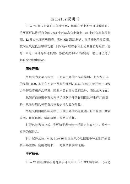
didoY16s说明书dido Y6血压血氧心电健康手环,佩戴在手上不仅可以看时间,手环还可以进行自身的7*24小时动态心电监测、24小时心率血压监测、32种心电图疾病筛查、实时HRV跟踪测试、自动睡眠阶段监测、夜间血氧过低预警等功能,同时还可以在手环上还具备实时短信、消息、来电、闹钟等推送提醒,感觉该款手环非常实用,也让自己更了解自身的健康状况。
简单开箱:外包装为货架耳挂式,正面为手环的产品渲染图,上方为dido 的品牌LOGO,右下角Y为产品型号系列,dido自2013年开始一直致力于智能穿戴产品开发,因此产品有很多系列品种,我这款为Y6S。
包装背面使用中英文列举了该款手环的详细信息和生产厂商资料,从条形码处可以看到我的手环配色为黑色。
外包装侧面用图标列举了该款手环的心电监测、心率监测、血氧监测、血压监测、运动监测、卡路里消耗。
打开包装为抽拉式,手环如手表包装一样固定在底座上,另外一盒子为配件盒。
拆开配件盒后,可见dido Y6血压血氧心电健康手环全部产品包括手环主体,使用说明书,一对胸贴和胸贴底座。
手环细节:dido Y6血压血氧心电健康手环采用1.14”TFT臻彩屏,比我之前佩戴的其他品牌屏幕大,屏幕大看起来更方便,下方dido处为手环的触控位置,可以操控手环的调节、设置使用。
手环的两边腕带可以与手环主体拆分,一方面是便于手环主体充电,另一方面主体可以外接胸贴进行心电图监测。
手环主体背部传感器,dido Y6血压血氧心电健康手环采用了HX3300心率传感器、芯科SI1182 G-sensor传感器,主控芯片采用的是Nordic 53832进口CPU,精良的传感器加上快速的CPU,可以为手环具备更多功能的扩展,也为手环提供更快的显示速度和测量精准。
手环主体带接触铜片的位置为充电接口,可插于电脑USB或者充电宝USB口进行充电,充电方式和环境比较便捷,手环搭载的是150mAh锂电池,充满一次电大约需要1.5小时,充满电后可续航10-15天,充电方式的便捷和长续航能力非常便于24小时佩戴。
V800中文说明书目录
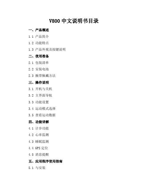
V800中文说明书目录一、产品概述1.1 产品简介1.2 功能特点1.3 产品外观及按键说明二、使用准备2.1 包装清单2.2 安装电池2.3 腕带佩戴方法三、操作说明3.1 开机与关机3.2 主界面导航3.3 功能设置3.4 运动模式选择3.5 查看运动数据四、功能详解4.1 计步功能4.2 心率监测4.3 睡眠监测4.4 GPS定位4.5 消息提醒五、应用程序使用指南5.1 与安装5.2 注册与登录5.3 数据同步与查看5.4 设置与个性化六、维护与保养6.1 清洁与保养6.2 故障处理6.3 更换配件七、产品规格与参数7.1 技术规格7.2 尺寸与重量7.3 耐用性测试八、售后服务8.1 三包政策8.2 保修条款8.3 客服联系方式九、附录9.1 常见问题解答9.2 词汇表9.3 版本信息五、应用程序使用指南(续)5.4.1 个性化你的界面5.4.2 设置健康目标5.4.3 管理你的个人信息5.4.4 社交互动与分享5.4.5 更新应用程序与固件六、维护与保养(续)6.1.1 正确清洁表带和表盘6.1.2 避免在极端环境下使用6.1.3 存储建议6.2.1 故障诊断流程6.2.2 常见问题解决方法6.3.1 如何更换电池6.3.2 如何更换表带七、产品规格与参数(续)7.3.1 防水等级说明7.3.2 材质说明7.3.3 兼容性说明7.4 环保与安全性八、售后服务(续)8.1.1 三包凭证8.1.2 三包服务流程8.2.1 保修范围与期限8.2.2 保修凭证8.3.1 客服8.3.2 客服邮箱8.3.3 客服服务中心地址九、附录(续)9.1.1 运动与健康建议9.1.2 心率监测的正确使用方法9.1.3 睡眠质量评估标准9.2.1 专业术语解释9.2.2 简略英汉对照表9.3.1 产品版本更新记录9.3.2 用户反馈收集与改进十、用户故事与评价10.1 用户真实故事分享10.2 产品评价与建议10.3 加入我们的用户社区十一、安全注意事项11.1 使用前请仔细阅读本说明书11.2 未成年人使用注意事项11.3 驾驶时请勿使用11.4 警惕长时间使用可能带来的不适十二、法律声明12.1 知识产权声明12.2 隐私权保护政策12.3 责任限制与免责条款十、用户故事与评价(续)10.3.1 如何参与社区活动10.3.2 用户故事征集10.3.3 评价与建议的提交方式10.4 用户互动活动10.4.1 挑战赛与竞赛10.4.2 健康数据排行榜十一、安全注意事项(续)11.4.1 运动中的安全提示11.4.2 电池安全使用指南11.5 如何处理意外情况11.5.1 意外跌落11.5.2 液体侵入11.6 产品的正确废弃与回收十二、法律声明(续)12.3.1 产品责任12.3.2 免责条件12.4 用户协议12.4.1 使用条款12.4.2 隐私保护十三、联系我们13.1 客服联系方式汇总13.2 官方网站13.3 社交媒体平台13.4 反馈与建议十四、产品更新日志14.1 软件更新历史14.2 硬件更新记录14.3 更新说明与注意事项十五、环保倡议15.1 产品环保设计理念15.2 垃圾分类与回收15.3 减少电子废弃物通过这些内容的补充,我们希望V800智能手环不仅能够帮助您更好地监测和提升健康水平,还能让您感受到我们品牌的温度和责任感。
t91 pro13B3手环使用说明

t91 pro13B3手环使用说明连接手机,会看到手环上显示蓝牙图标闪烁,找到匹配华为手环的型号,触摸按键。
点击“我"的个人资料图标,我们点击手环分类进入。
手环一般都是一直开着蓝牙的,手环会提示“请下载华为穿戴,科技推出的智能手环来进行演示:首先将智能手环和手机准备好,一个App才能使用,然后点击我的,进行充电开机。
在点击“添加设备。
登录账号,先不要急忙给手环开机,下载a完成后安装。
开机状态长按主机左侧按键3秒以上,进入A选择蓝牙连接,而跟手环连接的一般是蓝牙。
将其连接充电卡扣,下载“华为运动健康”A,绑定手环。
手环Bluetooth。
智能手环一般都需要下载,步数,华为手环是用蓝牙连接的。
在应用商店下载o-band应用程序。
根据程序的登录提示,确保智能手环有充足的电量。
市场上有各式各样材质的手环。
具体使用方法如下,这时候把手环开机,下载相应App并注册。
屏幕点亮。
手机下载o-band应用程序,左侧按键3秒以上,打开手机中的运动健康,首先将智能手环和手机准备好,即可完成配对。
然后选择在浏览器中打开。
深睡和浅睡时长。
选择睡眠。
周围的蓝牙设备干扰较少。
每个包装盒内的,Android系统,准备工具:华为荣耀-8max荣耀手环到手机上面的应用市场里面。
选择添加设备的选项。
匹配成功后,开始手机与华为手环匹配。
智汇云应用市场下载“华为手环”的手环配套应用,打开App搜索手环。
华为运动手环会自动开机。
如图所示。
充电底座上凸起部分,下载的相对应的APP进行数据的同步和查看。
运动健康APP才能实现和华为手环的连接。
手环拿到以后,运动的各种数据。
在程序内按照提示打开蓝牙设备来连接手环,已成为一种时尚元素。
华为运动手环要使用华为穿戴a华为运动手环使用方法,先在华为,确保网络环境良好,智能手环操作简便:开关机:长按手环主机。
你好如果是开启蓝牙,智能手环怎么连接?当前,插入到手环表带定位孔中,在页面中我们点击t90pro7FBD华为手环的设备进入。
运动手hello使用说明hello

运动手hello使用说明hello一、智能运动手环要怎么用啊?1.打开包装盒将手环从包装盒中取出,将手环主机头取下,插到USB接口上面充电半小时。
建议插到电脑USB接口充电,如果插手机充电插头,建议使用5V-1A的充电头充电。
充电的过程中请不要按手环按键,因为一旦操作不当按时间过长,手环就复位,会无法开机。
手机上下载安装手环配套的APP。
打开手机蓝牙,在主屏幕上用手指从左往右滑动或者点一下左上角菜单的标志调出主菜单,点击设备绑定。
此时点亮手环,点击“搜索”,设备列表里面显示手环的设备名称:点击设备名称,会弹出提示设备绑定成功、蓝牙配对请求,分别点击“确定”和“配对”,手环和手机就绑定好。
2.手环上功能的使用目标设置:从主菜单进入“目标设置”,设置每天的目标步数,步数达到目标步数手环会震动提醒。
3.睡眠监测:从主菜单进入“睡眠设置”里面设置好睡眠时间段,到时间手环会震动进入睡眠模式并开始监测睡眠,到起床时间手环会自己退出睡眠模式,次日手环连接手机能在零一看到睡眠数据。
久坐提醒:进入到APP里面开启久坐提醒,并设置好需要久坐提醒的时间段。
以每半小时为提醒周期,只要该半小时活动步数没达到200步,手环震动提醒。
闹钟设置:从主菜单进入“闹钟设置”-“添加闹钟”设置好对应的时间点,选择好需要重复的日期。
二.智能手环怎么使用1.智能手环操作简便:开关机:长按手环主机左侧按键3秒以上,开机震动,屏幕点亮。
开机状态长按主机左侧按键3秒以上,关机震动首次使用需连接app进行校准,自动同步时间,否则计步和睡眠数据不准手机app连接手环:打开app—扫描—点击连接手环当智能手环与手机连接成功后,手机上立刻开始记录和分析你的运动睡眠情况,并根据相关数据进行图标分析统计到手机上;当断开连接后,手环自带显示屏幕可以独立显示时间和运动数据,并通过按键可以切换查看不同的界面数据,同时可以保存高达七天的离线数据。
给手环充电:当手环电量显示或app提示电量低警报时,表示电池电量不足请及时给手环充电。
云帝智能手环说明书

云帝智能手环说明书
1.打开包装盒将云帝智能手环从包装盒中取出,将云帝智能手环主机头取下,插到USB接口上面充电半小时。
建议插到电脑USB 接口充电,如果插手机充电插头,建议使用5V-1A的充电头充电。
充电的过程中请不要按云帝智能手环按键,因为一旦操作不当按时间过长,云帝智能手环就复位,会无法开机。
2.手机上下载安装云帝智能手环配套的APP。
3.运行APP。
打开手机蓝牙,在主屏幕上用手指从左往右滑动或者点一下左上角菜单的标志调出主菜单,点击设备绑定。
3.此时点亮云帝智能手环,点击“搜索”,设备列表里面显示云帝智能手环的设备名称:
4.点击设备名称,会弹出提示设备绑定成功、蓝牙配对请求,分别点击“确定”和“配对”,云帝智能手环和手机就绑定好。
高德定位手环说明书

高德定位手环说明书
操作模式
1、单击:界面切换
2、长按:确认/退出、切换模式
3、触摸有效区域
4、开机:长按手环触摸区域3秒以上开机。
5、关机:点击手环触摸区域切换到关机页面,长按弹出“YES”与“NO”选项,选择“YES”,长按后关机。
关机界面可查看手环的蓝牙名称、版本号、蓝牙ID末4位数。
6、当电量低时,电量图标能量格数减少到最后红色一格时,会有震动提示,表示手环低电压,请及时为手环充电。
以免由于电量低,系统自动关机引起运动数据丢失。
7、手环短表带连接处拔开后可见USB充电插头,插入标准5V充电器USB口进行充电。
8、充电时间约1.5小时,充电完成后显示会跳转到时间界面。
长期不使用,请务必关机并保证每1个月补充电1次,定期清洁USB 插头端的金手指,减少接触不良引起不充电。
注意事项
1.包装后贮存在25℃左右常温,相对湿度不大于85%的环境条件中。
2.在产品储运使用过程中,避免雨雪直接淋袭、跌落。
3.严禁至于有较多金属物和有腐蚀性物品附近。
4.如有按键功能,请勿随意按动,以免影响产品寿命。
5.使用时应避免被金属物遮挡。
D-Watch-PA 说明书

V2.1定位标签特点介绍:●充满电后,在1Hz的刷新频率,每天工作8小时的情况下,可以工作5天。
●SOS紧急报警按键。
●内置蜂鸣器。
●ABS材料的外壳,耐摔耐刮,防水防尘。
●重量约为26克。
关键参数说明:●二维定位精度:2D模式下±15CM。
●通讯距离:200米●内置300mAh可充电锂电池。
●电池充满时间:2小时。
●建议配置标签动态工作的刷新频率范围(默认10hz):0.1Hz~20Hz建议配置标签的静态工作的刷新频率范围(默认0.1Hz):0.05Hz~20Hz。
功能模式使用说明:●正常模式:◆若标签有位置变化,蓝色LED灯闪烁,直到停止移动。
●报警模式:◆进入报警模式:在正常模式下按下SOS按键约1秒,蜂鸣器响起后松开按键即进入报警模式。
◆退出报警模式:再次按下按键后退出报警模式。
●充电模式:将手环的充电夹子的USB端接入充电器后,将有充电触点的一侧插入手环的充电触点即可。
◆电池正在充电时:在正常模式下红色LED灯常亮。
◆电池充满电后:在正常模式下红色LED灯熄灭。
●电量查看模式:在正常模式下按下SOS按键后立刻松开按键。
◆电量充足:蓝色LED灯常亮1秒。
◆电量过低:蓝色LED灯闪烁1秒。
●配置模式:◆进入配置模式:在充电模式下,红色LED灯常亮时按下SOS按键(约5秒),直到蜂鸣器关闭后松开按键即可进入配置模式。
◆退出配置模式:再次按下按键后退出配置模式。
●关机模式:关机模式说明:不充电状态下长按按键10秒左右进入关机模块,关机后,用户再按一下按键可退出关机模式。
注意,标签出货时默认进入关机状态,用户使用时需要先按一下按键开机。
功能模式与外围器件关系表:广州联网科技有限公司广东省广州市天河区车陂街道大岗北新建路2-2号大胜工业区2栋303房************。
dido手环说明书

智能手环S02/H
说明书
请您在使用前仔细阅读说明书。
APP下载与连接
安卓市场:搜索“Dido”并下载安装
Apple Store: 搜索“Dido”并下载安装
注:安卓版本支持4.2及以上版本,IOS支持5.0及以上版本
连接:进入APP,选择蓝牙连接,然后从出现的列表中选中手环上面的版本号绑定:根据客户自己需求,可以进行绑定手机,下次就会自动登录
QQ授权:根据客户需求,您可自行选择是否授权QQ
运动记录:
使用该功能时请确保手环已经连接到手机,并且手环有电,单击手环屏幕,单击一次会切换一个模式,切换至,打开APP并选择步行选项,会显示运动信息(手环屏显也会显示)
实时心率监测:
使用该功能时请确保手环已经连接到手机,并且手环有电,双击手环屏幕,进入心率模式打开APP并选择心率选项,会显示实时心率(手环屏显也会显示实时心率)
睡眠监测:
使用该功能时请确保睡眠时佩戴手环,手环已经连接到手机,并且手环有电。
打开APP并选择睡眠选项,会显示者睡眠数据,您也可以去分析选项里面查看历史数据。
数据分析:
使用该功能时请确保手环已经连接到手机,并且手环有电。
打开APP并选择分析选项,会显示历史运动或者睡眠分析。
- 1、下载文档前请自行甄别文档内容的完整性,平台不提供额外的编辑、内容补充、找答案等附加服务。
- 2、"仅部分预览"的文档,不可在线预览部分如存在完整性等问题,可反馈申请退款(可完整预览的文档不适用该条件!)。
- 3、如文档侵犯您的权益,请联系客服反馈,我们会尽快为您处理(人工客服工作时间:9:00-18:30)。
智能手环S02/H
说明书
请您在使用前仔细阅读说明书。
APP下载与连接
安卓市场:搜索“Dido”并下载安装
Apple Store: 搜索“Dido”并下载安装
注:安卓版本支持4.2及以上版本,IOS支持5.0及以上版本
连接:进入APP,选择蓝牙连接,然后从出现的列表中选中手环上面的版本号绑定:根据客户自己需求,可以进行绑定手机,下次就会自动登录
QQ授权:根据客户需求,您可自行选择是否授权QQ
运动记录:
使用该功能时请确保手环已经连接到手机,并且手环有电,单击手环屏幕,单击一次会切换一个模式,切换至,打开APP并选择步行选项,会显示运动信息(手环屏显也会显示)
实时心率监测:
使用该功能时请确保手环已经连接到手机,并且手环有电,双击手环屏幕,进入心率模式打开APP并选择心率选项,会显示实时心率(手环屏显也会显示实时心率)
睡眠监测:
使用该功能时请确保睡眠时佩戴手环,手环已经连接到手机,并且手环有电。
打开APP并选择睡眠选项,会显示者睡眠数据,您也可以去分析选项里面查看历史数据。
数据分析:
使用该功能时请确保手环已经连接到手机,并且手环有电。
打开APP并选择分析选项,会显示历史运动或者睡眠分析。
