机械设计与制造毕业设计论文中英文翻译外文翻译--如何延长轴承寿命
机械设计制造及自动化中英文对照外文翻译文献
机械设计制造及⾃动化中英⽂对照外⽂翻译⽂献中英⽂对照外⽂翻译⽂献(⽂档含英⽂原⽂和中⽂翻译)使⽤CBN砂轮对螺杆转⼦进⾏精密磨削的⽅法摘要:针对⾼精度加⼯螺杆转⼦,这篇论⽂介绍了利⽤⽴⽅氮化硼(CBN砂轮)对螺杆转⼦进⾏精密磨削的加⼯⽅法。
⾸先,使⽤⼩型电镀CBN砂轮磨削螺杆转⼦。
精确的CBN砂轮轴向轮廓的模型是在齿轮啮合理论的基础上建⽴开发的。
考虑到螺杆转⼦和涂层厚度之间的间隙,主动砂轮的修整引⼊了CBN的砂轮的设计⽅法。
主动砂轮的形状采⽤低速电⽕花线切割技术(低速⾛丝线切割机)进⾏加⼯线CBN主动砂轮的成形车⼑采⽤低速⾛丝机切割机进⾏加⼯。
CBN螺杆转⼦砂轮采⽤本⽂提出的原理进⾏有效性和正确性的验证。
电镀CBN砂轮对螺杆转⼦进⾏加⼯,同时进⾏机械加⼯实验。
在实验中获得的数据达到GB10095-88五级认证。
关键词: CBN砂轮精密磨削螺杆转⼦砂轮外形修整专业术语⽬录:P 螺杆转⼦的参数H 螺杆转⼦的直径Σ砂轮和转⼦的安装⾓度Au 砂轮和转⼦的中⼼距8 螺旋转⼦接触点的旋转⾓x1, y1, z1:转⼦在σ系统中的位置x, y, z: 砂轮端⾯的位置x u ,y u ,z u: x, x y z轴的法向量n x ,ny,nz:X Y Z轴的端⾯法向量n u , nu, nu:砂轮的⾓速度的⽮量:砂轮模块的⾓速度wu:螺旋转⼦的⾓速度w1螺旋转⼦模块的⾓速度转⼦接触点的⾓速度转⼦表⾯接触点的初始速度砂轮表⾯接触点的⾓速度砂轮表⾯接触点的初始速度l砂轮的理论半径砂轮轴的理想位置砂轮表⾯的修改半径砂轮轴的修改位置砂轮表⾯的法向量1.引⾔螺旋转⼦是螺杆压缩机、螺钉、碎纸机以及螺杆泵的关键部分。
转⼦的加⼯精度决定了机械性能。
⼀般来说,铣⼑⽤于加⼯螺旋转⼦。
许多研究者,如肖等⼈[ 1 ]和姚等⼈[ 2 ],对⽤铣⼑加⼯螺旋转⼦做了⼤量的⼯作。
该⽅法可以提⾼加⼯效率。
然⽽,加⼯精度低和表⾯粗糙度不⾼是其主要缺点。
毕业设计论文外文文献翻译机械设计制造及其自动化轴承的摩擦与润滑中英文对照
Friction , Lubrication of BearingIn many of the problem thus far , the student has been asked to disregard or neglect friction . A ctually , friction is present to some degree whenever two parts are in contact and move on each other. The term friction refers to the resistance of two or more parts to movement.Friction is harmful or valuable depending upon where it occurs. friction is necessary for fastening devices such as screws and rivets which depend upon friction to hold the fastener and the parts together. Belt drivers, brakes, and tires are additional applications where friction is necessary.The friction of moving parts in a machine is harmful because it reduces the mechanical advantage of the device. The heat produced by friction is lost energy because no work takes place. A lso , greater power is required to overcome the increased friction. Heat is destructive in that it causes expansion. Expansion may cause a bearing or sliding surface to fit tighter. If a great enough pressure builds up because made from low temperature materials may melt.There are three types of friction which must be overcome in moving parts: (1)starting, (2)sliding,and(3)rolling. Starting friction is the friction between two solids that tend to resist movement. When two parts are at a state of rest, the surface irregularities of both parts tend to interlock and form a wedging action. T o produce motion in these parts, the wedge-shaped peaks and valleys of the stationary surfaces must be made to slide out and over each other. The rougher the two surfaces, the greater is starting friction resulting from their movement .Since there is usually no fixed pattern between the peaks and valleys of two mating parts, the irregularities do not interlock once the parts are in motion but slide over each other. The friction of the two surfaces is known as sliding friction. A s shown in figure ,starting friction is always greater than sliding friction .Rolling friction occurs when roller devces are subjected to tremendous stress which cause the parts to change shape or deform. Under these conditions, the material in front of a roller tends to pile up and forces the object to roll slightly uphill. This changing of shape , known as deformation, causes a movement of molecules. As a result ,heat is produced from the added energy required to keep the parts turning and overcome friction.The friction caused by the wedging action of surface irregularities can be overcome partly by the precision machining of the surfaces. However, even these smooth surfaces may require the use of a substance between them to reduce the friction still more. This substance is usually a lubricant which provides a fine, thin oil film. The film keeps the surfaces apart and prevents the cohesive forces of the surfaces from coming in close contact and producing heat .Another way to reduce friction is to use different materials for the bearing surfaces and rotating parts. This explains why bronze bearings, soft alloy s, and copper and tin iolite bearings are used with both soft andhardened steel shaft. The iolite bearing is porous. Thus, when the bearing is dipped in oil, capillary action carries the oil through the spaces of the bearing. This type of bearing carries its own lubricant to the points where the pressures are the greatest.Moving parts are lubricated to reduce friction, wear, and heat. The most commonly used lubricants are oils, greases, and graphite compounds. Each lubricant serves a different purpose. The conditions under which two moving surfaces are to work determine the type of lubricant to be used and the system selected for distributing the lubricant.On slow moving parts with a minimum of pressure, an oil groove is usually sufficient to distribute the required quantity of lubricant to the surfaces moving on each other .A second common method of lubrication is the splash system in which parts moving in a reservoir of lubricant pick up sufficient oil which is then distributed to all moving parts during each cycle. This system is used in the crankcase of lawn-mower engines to lubricate the crankshaft, connecting rod ,and parts of the piston.A lubrication system commonly used in industrial plants is the pressure system. In this system, a pump on a machine carries the lubricant to all of the bearing surfaces at a constant rate and quantity.There are numerous other sy stems of lubrication and a considerable number of lubricants available for any given set of operating conditions. Modern industry pays greater attention to the use of the proper lubricants than at previous time because of the increased speeds, pressures, and operating demands placed on equipment and devices.Although one of the main purposes of lubrication is reduce friction, any substance-liquid , solid , or gaseous-capable of controlling friction and wear between sliding surfaces can be classed as a lubricant.V arieties of lubricationUnlubricated sliding. Metals that have been carefully treated to remove all foreign materials seize and weld to one another when slid together. In the absence of such a high degree of cleanliness, adsorbed gases, water vapor ,oxides, and contaminants reduce frictio9n and the tendency to seize but usually result in severe wear。
(机械制造行业)机械外文翻译中英文
Engine lathes, of course, are general-purpose machine used in production and maintenance shop all over the the world. Sized ranger from small bench models to huge heavy duty pieces of equipment. Many of the larger lathes come equipped with attachments not commonly found in the ordinary shop, such as automatic shop for the carriage.
Because the high quality and low price of ball and roller bearing depends on quantity production,the task of the machine designer becomes one of selection rather than design. Rolling-contact bearings are generally made with steel which is through-hardened to about 900HV,although in many mechanisms special races are not provided and the interacting surfaces are hardened to about 600HV. It is not surprising that,owing to the high stresses involved,a predominant form of failure should be metal fatigue, and a good deal of work is based on accept values of life and it is general practice in b load capacity of the bearing as that value below which 90 percent of a batch will exceed life of one million revolutions.
机械类文章翻译案例 中英对照

妙文翻译公司翻译样稿One concept – the whole system for all functions一个概念–具有所有功能的整体系统Power units动力单元The power unit is the heart of the turbine, supplying the power necessary to operate pitch, yaw and braking systems and providing backup in case of power failure, ensuring a safe stop with no risk of damage.Our hydraulic power units are designed with reliabilty, ease of maintenance and a wide operating temperature range in mind.动力单元是风轮机的心脏,为浆距、偏航和制动系统的运行提供必要的电力,并在断电时提供备用措施,保证安全停止,无损坏危险。
我们的液压动力单元在设计时充分考虑了可靠性、维护方便性及宽温度范围。
Added life寿命增加Parker filtration technology extends the life and increases the reliability of wind turbines by using environmental solutions.In addition to a wide range of hydraulic filters, lube filters and reservoir accessories, Parker offers you the global leader in fluid condition monitoring with the Laser CM portable particle counter.A comprehensive range of quality products to cover all your needs!通过应用环境条件解决方案,Parker过滤技术延长了风轮机的寿命并提高了可靠性。
机械设计专业外文文献翻译

机械设计专业外文文献翻译general。
however。
materials that are easy to machine have high machinability。
while those that are difficult to machine have low XXX。
microstructure。
and mechanical properties。
as well as the XXX。
material。
and wear resistance.XXX factors。
cutting speed。
feed rate。
and depth of cut also play XXX the amount of heat generated in the cutting zone and decreasing the time that the cutting tool is in contact with the XXX。
at high cutting speeds。
tool wear and cutting forces can increase。
which can ce tool life and surface finish quality.Feed rate and depth of cut also XXX the amount of material that is removed and the forces that are generated during cutting。
Higher feed rates and deeper cuts can improve material removal rates。
but they can also increase cutting forces and heat n。
which can ce tool life and surface finish quality.Overall。
机械设计与制造毕业设计论文中英文翻译外文翻译

毕业设计(论文)外文翻译如何延长轴承寿命摘要:自然界苛刻的工作条件会导致轴承的失效,但是如果遵循一些简单的规则,轴承正常运转的机会是能够被提高的。
在轴承的使用过程当中,过分的忽视会导致轴承的过热现象,也可能使轴承不能够再被使用,甚至完全的破坏。
但是一个被损坏的轴承,会留下它为什么被损坏的线索。
通过一些细致的侦察工作,我们可以采取行动来避免轴承的再次失效。
关键词:轴承失效寿命轴承(“Bearing”,日本人称“轴受”)是在机械传动过程中起固定和减小载荷摩擦系数的部件。
也可以说,当其它机件在轴上彼此产生相对运动时,用来降低动力传递过程中的摩擦系数和保持轴中心位置固定的机件。
轴承是当代机械设备中一种举足轻重的零部件。
它的主要功能是支撑机械旋转体,用以降低设备在传动过程中的机械载荷摩擦系数。
按运动元件摩擦性质的不同,轴承可分为滚动轴承和滑动轴承两类。
1.轴承寿命的基本概念根据最新的轴承疲劳寿命理论,一只设计优秀、材质卓越、制造精良而且安装正确的轴承,只要其承受的负荷足够轻松(不大于该轴承相应的某个持久性极限负荷值),则这个轴承的材料将永远不会产生疲劳损坏。
因此,只要轴承的工作环境温度适宜而且变化幅度不大,绝对无固体尘埃、有害气体和水分侵入轴承,轴承的润滑充分而又恰到好处,润滑剂绝对纯正而无杂质,并且不会老化变质,则这个轴承将会无限期地运转下去。
这个理论的重大意义不仅在于它提供了一个比ISO寿命方程更为可靠的预测现代轴承寿命的工具,而且在于它展示了所有轴承的疲劳寿命都有着可观的开发潜力,并展示了开发这种潜力的途径,因而对轴承产品的开发、质量管理和应用技术有着深远的影响。
但是,轴承的无限只有在实验室的条件下才有可能“实现”,而这样的条件对于在一定工况下现场使用的轴承来说,既难办到也太昂贵。
现场使用轴承,其工作负荷往往大于其相应的疲劳持久性极限负荷,在工作到一定的期限后,或晚或早总会由于本身材料达致电疲劳极限,产生疲劳剥落而无法继续使用。
机械制造专业外文翻译-轴、联轴器和滚动轴承
外文原文:shafts、couplings and rolling contact bearingskey words: shafts、couplings、bearingsVirtually all machines contain shafts.The most common shape for shafts is circular and the cross section can be either solid or hollow (hollow shafts can result in weight savings ).Rectangular shafts are sometimes used ,as in screwdriver blades,socket wrenches and control knob stems .A shaft must have adequate torsional strength to transmit torque and not be overstressed. It also be torsionally stiff enough so that one mounted component does not deviate excessively from its original angular position relative to a second component mounted on the same shaft. Generally speaking ,the angle of twist should not exceed one degree in a shaft length equal to 20 diameters.Shafts are mounted inbearings and transmint power through such devices as gears, pullerys, cams and clutches. These devices introduce forces which attempt to bend the shaft; hence, the shaft must be rigid enough to prevent overloading of the supporting bearings. In general, the bending deflection of a shaft should not exceed 0.01 in. per ft of length between bearing supports.In addition, the shaft must be able to sustain a combination of bending and torsional loads. Thus an equivalent load must be consideredwhich takes into account both torsion and bending. Also, the allowable stress must contain a factor of safety which includes fatigue, since torsional and bending stress reversals occur.For diameters less than 3 in. , the usual shaft material is cold-rolled ateel containing about 0.4 percent carbon. Shafts are either cold-rolled or forged in sizes from 3 in. to 5 in. ,shafts are forged and machined to size .Pleastic shafts are widely used for light load applications. One advantage of using plastic is safety in electrical applications ,since plastic is a poor conductor of electricity.Components such as gears and pulleys are mounted on shafts by means of key .The design of the key and the corresponding keyway in the shaft must be prperly evaluated. For example ,stress concentrations occur in shafts due to keyways ,and the material removed to form the keyway further weakens the shaft.If shafts are run at cirtical speeds ,severe vibrations can occur which can seriously damage a machine. It is important to know the magnitude of these critical speeds so that they can be avoided. As a general rule of thumb,the difference between the operating speed and the critical speed should be at least 20 percent .Another important aspect of shaft design is the method of directly connecting one shaft to another. This is accomplished by devices such as rigid and flexible couplings.A coupling is a device for connecting the eds of adjacent shafts. In machine construction, ouplings are used to effect a semipermanent connection between adjacent rotating shafts. The connection is permanent in the sense that it is not meant to be broken during the useful life of the machine, but it can be broken and restored in an emergency or when worn parts are replaced.There are several types of shaft couplings, their characteristics depend on the purpose for which they are used. If an exceptionally long shaft is required in a manufacturing plant or a propeller shaft on a ship, it is made in sections that are coupled together with rigid couplings. A common type of rigid coupling consists of two mating radial flanges(disks) that are cttached by key-driven hubs to the eds of adjacent shaft sections and bolted together through the flanges to form a rigid connection. Alignment of the connected shafts is usually effeted by means of a rabbet joint on the face of the flanges.In connecting shafts belonging to separate devices (such as an electric motor and a gearbox ),precise aligning of the shafts is difficult and a flexible coupling is used. This coupling connects theshafts in such a way as to minimize the harmful effects of shaft misalignment. Flexible couplings also permit the shafts to deflect under their separate systems of with one another. Flexible couplings can also serve to reduce the intensity of shock loads and vibrations transmitted from one shaft to another.Virtually all shafts contain rolling contact bearings.The concern of a machine designer with ball and roller bearings is fivefold as follows:(a) life in relation to load; (b) stiffness ,i.e. deflections under load; (c) friction;(d) wear; (e) noise. For moderate loads and speeds the correct selection of a standard bearing on the basis of load rating will usually secure satisfactory performance. The deflection of the bearing elements will become important where loads are high, although this is usuallyof less magnitude than that of the shafts or other components associated with the bearing. Where speeds are high special cooling arrangements become necessary which may increase frictional drag. Wear is primarily associated with the introduction of contaminants, and sealing arrangements must be chosen with regard the hostility of the environment.Because the high quality and low price of ball and roller bearings depends on quantity production, the task of the machine designer becomes one of selection rather than design. Rolling-contact bearings are generally made with ateel which is through-hardened toabout 900HV,although in many mechanisms special races are not provided and the interacting surfaces are hardened to about 600 HV. It is not surprising that, owing to the high stresses involved, a predominant form of failure should be metal fatigue, and a good deal of work is currently in progress intended to improve the reliability of this type of bearing. Design can bebased on accepted values of life and it is generral practice in the bearing industry to define the load capacity of the bearing as that value below which 90 lpercent of a batch will exceed a lift of ane million revolutions.Notwithstanding the fact that responsibility for the basic design of ball and roller bearings rests with the bearing manufacturer, the machine designer must form a correct appreciation of the duty to be performed by the bearing and be concerned not only with bearing selection but with the conditions for correct installation.The fit of the bearing races onto the shaft or onto the housings is of critical importance because of their combined effect on the internal clearance of the bearing as well as preserving the desired degree of interference fit. Inadequate interference can induce serious trouble from fretting corrosion. The inner race is frequently located axially by abutting against a shoulder. A radius at this point is essential for the avoidance of stress concentration and ball races are provides with a radius or chamfer to allow space for this .Where life is not the determining factor in design, it is usual to determine maximum loading by the amount towhich a bearing will deflect under load. Thus the concept of “static load-carrying capacity” is understood to mean the load that can be alpplied to a bearing, which is either stationary or subject to slight swiveling motions, without impairing its running qualities for subsequent rotational motion. This has beendetermined by practical experience as the load which when applied to a bearing results in a total deformation of the rolling element and raceway at any point of contact not exceeding 0.01 percent of the rolling-element diameter. This would correspond to a permanent deformation of 0.00025 mm for a ball 25mm in diameter.The successful functioning of many bearing depends upon providing them with adequate protection against their environment, and in some circumstances the enviroration of the bering surfaces. Achievement of the correct functioning of seals is an essential part of bearing design. Moreover, seals which are applied to moving parts for any purpose are of interest to tribologists because they are components of bearing systems and can only be designed satisfactorily on the basis of the approlpriate bearing theory. Notwithstanding their importance, the amount of research effort that has been devoted to the understanding of the understanding of the behavior of seals has been small when compared with that devoted to other aspects of bearing technology.References:1 Erickson.Belt and Application for Engineers.Marcel Dekker.Inc,19972 South,Mancuso.Mechanical Power Transmission Components.1994中文译文:轴、联轴器和滚动轴承关键词:轴、联轴器、轴承实际上,几乎所有的机器中都装有轴。
机械设计外文文献翻译、中英文翻译

机械设计外文文献翻译、中英文翻译unavailable。
The first step in the design process is to define the problem and XXX are defined。
the designer can begin toXXX evaluated。
and the best one is XXX。
XXX.Mechanical DesignA XXX machines include engines。
turbines。
vehicles。
hoists。
printing presses。
washing machines。
and XXX and methods of design that apply to XXXXXX。
cams。
valves。
vessels。
and mixers.Design ProcessThe design process begins with a real need。
Existing apparatus may require XXX。
efficiency。
weight。
speed。
or cost。
while new apparatus may be XXX。
To start。
the designer must define the problem and XXX。
ideas and concepts are generated。
evaluated。
and refined until the best one is XXX。
XXX.XXX。
assembly。
XXX.During the preliminary design stage。
it is important to allow design XXX if some ideas may seem impractical。
they can be corrected early on in the design process。
中英文文献翻译-如何延长轴承寿命
英文原文EXTENDING BEARING LIFEAbstract:Nature works hard to destroy bearings, but their chances of survival can be improved by following a few simple guidelines. Extreme neglect in a bearing leads to overheating and possibly seizure or, at worst, an explosion. But even a failed bearing leaves clues as to what went wrong. After a little detective work, action can be taken to avoid a repeat performance.Keywords: bearings failures lifeBearings fail for a number of reasons,but the most common are misapplication,contamination,improper lubricant,shipping or handling damage,and misalignment. The problem is often not difficult to diagnose because a failed bearing usually leaves telltale signs about what went wrong.However,while a postmortem yields good information,it is better to avoid the process altogether by specifying the bearing correctly in The first place.To do this,it is useful to review the manufacturers sizing guidelines and operating characteristics for the selected bearing. Equally critical is a study of requirements for noise, torque, and runout, as well as possible exposure to contaminants, hostile liquids, and temperature extremes. This can provide further clues as to whether a bearing is right for a job. 1 Why bearings fail About 40% of ball bearing failures are caused by contamination from dust, dirt, shavings, and corrosion. Contamination also causes torque and noise problems, and is often the result of improper handling or the application environment.Fortunately, a bearing failure caused by environment or handling contamination is preventable,and a simple visual examination can easily identify the cause.Conducting a postmortem il1ustrates what to look for on a failed or failing bearing.Then,understanding the mechanism behind the failure, such as brinelling or fatigue, helps eliminate the source of the problem.Brinelling is one type of bearing failure easily avoided by proper handing and assembly. It is characterized by indentations in the bearing raceway caused by shock loading-such as when a bearing is dropped-or incorrect assembly. Brinelling usually occurs when loads exceed the material yield point(350,000 psi in SAE 52100 chrome steel).It may also be caused by improper assembly, Which places a load across the races.Raceway dents also produce noise,vibration,and increased torque. A similar defect is a pattern of elliptical dents caused by balls vibrating between raceways while the bearing is not turning.This problem is called false brinelling. It occurs on equipment in transit or that vibrates when not in operation. In addition, debris created by false brinelling acts like an abrasive, further contaminating the bearing. Unlike brinelling, false binelling is often indicated by a reddish color from fretting corrosion in the lubricant. False brinelling is prevented by eliminating vibration sources and keeping the bearing well lubricated. Isolation pads on the equipment or a separate foundation may be required to reduce environmental vibration. Also a lightpreload on the bearing helps keep the balls and raceway in tight contact. Preloading also helps prevent false brinelling during transit. Seizures can be caused by a lack of internal clearance, improper lubrication, or excessive loading. Before seizing, excessive, friction and heat softens the bearing steel. Overheated bearings often change color,usually to blue-black or straw colored.Friction also causes stress in the retainer,which can break and hasten bearing failure.Premature material fatigue is caused by a high load or excessive preload.When these conditions are unavoidable,bearing life should be carefully calculated so that a maintenance scheme can be worked out.Another solution for fighting premature fatigue is changing material.When standard bearing materials,such as 440C or SAE 52100,do not guarantee sufficient life,specialty materials can be recommended. In addition,when the problem is traced back to excessive loading,a higher capacity bearing or different configuration may be used.Creep is less common than premature fatigue.In bearings.it is caused by excessive clearance between bore and shaft that allows the bore to rotate on the shaft.Creep can be expensive because it causes damage to other components in addition to the bearing.0ther more likely creep indicators are scratches,scuff marks,or discoloration to shaft and bore.To prevent creep damage,the bearing housing and shaft fittings should be visually checked.Misalignment is related to creep in that it is mounting related.If races are misaligned or cocked.The balls track in a noncircumferencial path.The problem is incorrect mounting or tolerancing,or insufficient squareness of the bearing mounting site.Misalignment of more than 1/4·can cause an early failure.Contaminated lubricant is often more difficult to detect than misalignment or creep.Contamination shows as premature wear.Solid contaminants become an abrasive in the lubricant.In addition。
轴类毕业设计英文翻译、外文文献翻译
ShaftSolid shafts. As a machine component a shaft is commonly a cylindrical bar that supports and rotates with devices for receiving and delivering rotary motion and torque .The crankshaft of a reciprocating engine receive its rotary motion from each of the cranks, via the pistons and connecting roads (the slider-crank mechanisms), and delivers it by means of couplings, gears, chains or belts to the transmission, camshaft, pumps, and other devices. The camshafts, driven by a gear or chain from the crankshaft, has only one receiver or input, but each cam on the shaft delivers rotary motion to the valve-actuating mechanisms.An axle is usually defined as a stationary cylindrical member on which wheels and pulleys can rotate, but the rotating shafts that drive the rear wheels of an automobile are also called axles, no doubt a carryover from horse-and-buggy days. It is common practice to speak short shafts on machines as spindles, especially tool-carrying or work-carrying shafts on machine tools.In the days when all machines in a shop were driven by one large electric motor or prime mover, it was necessary to have long line shafts running length of the shop and supplying power, by belt, to shorter couter shafts, jack shafts, or head shafts. These lineshafts were assembled form separate lengths of shafting clampled together by rigid couplings. Although it is usually more convenient to drive each machine with a separate electric motor, and the present-day trend is in this direction, there are still some oil engine receives its rotary motion from each of the cranks, via the pistons and connecting roads (the slider-crank mechanisms) , and delivers it by means of couplings, gears, chains or belts to the transmission, camshaft, pumps, and other devices. The camshafts, driven by a gear or chain from the crankshaft, has only one receiver or input, but each cam on the shaft delivers rotary motion to the valve-actuating mechanisms.An axle is usually defined as a stationary cylindrical member on which wheels and pulleys can rotate, but the rotating shafts that drive the rear wheels of an automobile are also called axles, no doubt a carryover from horse-and-buggy days. It is common practice to speak short shafts on machines as spindles, especially tool-carrying or work-carrying shafts on machine tools.In the days when all machines in a shop were driven by one large electric motor or prime mover, it was necessary to have long line shafts running length of the shop and supplying power, by belt, to shorter coutershafts, jackshafts, or headshafts. These line shafts were assembled form separatelengths of shafting clampled together by rigid couplings. Although it is usually more convenient to drive each machine with a separate electric motor, and the present-day trend is in this direction, there are still some situation in which a group drive is more economical.A single-throw crankshaft that could be used in a single-cylinder reciprocating engine or pump is shown in Figure 21. The journals A andB rotate in the main bearings,C is the crankpin that fits in a bearing on the end of the connecting rod and moves on a circle of radius R about the main bearings, whileD andE are the cheeks or webs.The throw R is one half the stroks of the piston, which is connected, by the wrist pin, to the other end of the connecting rod and guided so as to move on a straight path passing throw the axis XX. On a multiple-cylinder engine the crankshaft has multiple throws---eight for a straight eight and for a V-8---arranged in a suitable angular relationship.Stress and strains. In operation, shafts are subjected to a shearing stress, whose magnitude depends on the torque and the dimensions of the cross section. This stress is a measure of resistance that the shaft material offers to the applied torque. All shafts that transmit a torque are subjected to torsional shearing stresses.In addition to the shearing stresses, twisted shafts are also subjected to shearing distortions. The distorted state is usually defined by the angle of twist per unit length; i.e., the retation of one cross section of a shaft relative to another cross section at a unit distance from it.Shafts that carry gears and pulleys are bent as well as twisted, and the magniude of the bending stresses, which are tensile on the convex side of the bend and compressive on the concave side, will depend on the load, the distance between the bearings of the shaft cross section.The combination of bending and twisting produces a state of stress in the shaft that is more complex than the state of pure shears produced by torsion alone or the state of tension-compression produced by bending alone.To the designer of shaft it is important to know if the shaft is likely to fail because of an excessive normal stress. If a piece of chalk is twisted, it will invariably rupture on a plane at about 45 degrees to the axis. This is because the maximum tensile stresses act on this plane, and chalk is weak in tension. Steel shafting is usually designed so that the maximum shearing stress produced by bending and torsion is less than a specified maximum.Shafts with circular cross sections are easier to produce in the steel mill, easier to machine, andeasier to support in bearings than shafts with other cross section; there is seldom any need for using noncircular shapes. In addition, the strength and stiffness, both in bending and torsion, are more easily calculated for circular shafts. Lastly, for a given amount of materials the circular shafts has the smallest maximum shearing stress for a given torque, and the highest torsional rigidity.The shearing in a circular shaft is highest at the surface and drops off to zero at the axis. This means that most of the torque is carried by the material on and near the surface.Critical speeds. In the same way that a violin string vibrates when stroked with a bow, a cylindrical shaft suspended between two bearings has a natural frequency of lateral vibration. If the speed of revolution of the shaft coincides with the natural frequency, the shaft experience a whirling critical speed and become noisy. These speeds are more likely to occur with long, flexible shafts than with short, stiff ones. The natural frequency of a shaft can be raised by increasing its stiffness.If a slender rod is fixed to the ceiling ta one end and supports a heavy disk at the other end, the disk will oscillate back and forth around the rod axis like a torsion pendulum if given an initial twist and let go. The frequency of the oscillations will depend on the torsional stiffness of the rod and the weight of the disk; the stiffer the rod and the lighter the disk the higher the frequency. Similar torsional oscillations can occur in the crankshafts of reciprocating engines, particularly those with many crank throws and a heavy flywheel. Each crank throw and part of the associated connecting rod acts like a small flywheel, and for the crankshaft as a whole, there are a number of ways or modes in which there small flywheels can oscillate back and forth around the shaft axis in opposition to one another and to the main flywheel. For each of these modes there corresponds a natural frequency of oscillation.When the engine is operating the torques delivered to the crankshaft by the connecting rods fluctuate, and if the crankshaft speed is such that these fluctuating impulses are delivered at a speed corresponding to one of the natural torsional frequencies of the shaft, torsional oscillations will be superimposed on the rotary motion of the shafts. Such speed are known as torsional critical speeds, and they can cause shaft failures. A number of devices to control the oscillations of crankshafts have been invented.Flexible shafts. A flexible shaft consists of a number of superimposed tightly wound right-and left-hand layers of helically wound wires wrapped about a single center wire or mandrel. The shaft is connected to source of power and the driven member by special fittings attached to the end of theshaft. Flexible easings of metallic or nonmetallic materials, which guide and protect the shaft and retain the lubricant, are also available. Compared with solid shafts, flexible shafts can be bent to much smaller radii without being overstressed.For transmitting power around corners and for considerable distances flexible shafts are usually cheaper and more convenient than belts, chains, or gears. Most speedometers on automobiles are driven by flexible shafts running from the transmission to the dashboard. When a valve, a switch, or other control devices is in a hard-to-reach location, it can be operated by a flexible shaft from a more convenient position. For portable tools such as sanders, grinders, and drilling machines, flexible shafts are practically indispensable.KEY, SPLINES AND PINSKeys, splines, and pins. When power is being transmitted from a machine member such as a coupling, a gear, a flywheel, or a pulley to the shaft on which it is mounted, means must be provided for preventing relative motion between the shaft and the member. On helical and bevel gears, relative movement along the shaft caused by the thrust(axial) loads is prevented by a step in the shaft or by having the gear contact the bearing directly or through a tubular spacer. When axial loads are incidental and of small magnitude, the members are kept from sliding along the shaft by means of a set screw. The primary purpose of keys, splines, and pins is to prevent relative rotary movement.A commonly used type of key has a square cross section and is sunk half in the shaft and half in the hub of the other member. If the key is made of steel(which is commonly the case)of the same strength as the shaft and has a width and depth equal to one fourth of the shaft diameter(this proportion is closely approximated in practice) then it will have the same torque capacity as the solid shaft if its length is 1.57 times that of the shaft diameter. Another common type of key has a rectangular cross section with a depth to width ratio of 0.75. Both of these keys may either be straight or tapered in depth. The straight keys fit snugly on the sides of the key ways only, the tapered keys on all sides. Gib-head keys are tapered keys with a projection on one end to facilitate removal.Woodruff keys are widely used on machine tools and motor vehicles. The key is a segment of adisk and fits in a keyway in the shaft that is with a special milling cutter. Though the extra depth of these keys weakens the shaft considerably, it prevents any tendency of the key to rotate or move axially. Woodruff keys are particularly suitable for tapering shaft ends.Because they weaken the shafts less, keys with straight or tapered circular cross sections are sometimes used in place of square and rectangular keys, but the keyways, half in the shaft and half in the shaft and half in the hub, must be cut with a drill after assembly,and interchangeability of parts is practically impossible. When a large gear blank is made by shrinking a high-strength rim on a cheaper cast center, circular keys, snugly fitted, are frequently used to ensure a permanent connection.Splines are permanent keys integral with the shaft, fitting in keyways cut in the hub. The dimensions of splined fittings are standardized for both permanent (press) fits and sliding fits. The teeth have either straight or involute profiles;the latter are stronger, more easily measured, and have a self-centring action when twisted.Tapered circular pins can be used to restrain shaft-mounted members from both axial and rotary movement. The pin fits snugly in a reamed tapered hole that is perpendicular to the shaft surface. A number of straight pins that grip by deforming elastically or plastically when driven into straight holes are commercially available.All the keys and pins that have been described are standard driving devices. In some cases they inadequate, and unorthodox means must be employed. For driving small gear in which there is no room between the bore and the roots of the teeth for a longitudinal keyway, a transverse radial slot on the end of the gear can be made to fit a radial protuberance on the shaft. For transmitting moderate loads, a cheaper and effective connection can be made by forming a series of longitudinal serrations on the shaft with a knurling tool and pressing the shaft into the hole in the driven member, it will cut grooves in the hole and provide, in effect, a press-fitted splined connection. Press and shrink fits are also used, and they can provide surprisingly firm connections, but the dimensions of the connected member must be closely controlled.轴实心轴轴作为机械零件通常是一根圆柱形杆,用来支撑部件并随部件一起转动以接受和传递转动和扭矩。
轴承寿命分析外文翻译

轴承寿命分析外文翻译
the influence of lubrication on contact fatigue life is discussed from the standpoint of EHL film generation. There are also other lubrication-related effects that can affect the outcome of the test series.The firstis particulate contaminants in the lubricant. Depending on bearing size, operating speed, and lubricant rheology, the overall thickness of the lubricant film developed at the rolling element-raceway contacts may fall between 0.05 and 0.5 m . Solid particles and damage the raceway and rolling element surfaces, leading to substantially shortened endurances.
北方民族大学毕业设计
外文翻译
翻译题目:轴承失效分析
姓 名向延标
学 号20091210
影响耐久性强度的因素 机械设计及制造专业毕业设计外文翻译中英文对照
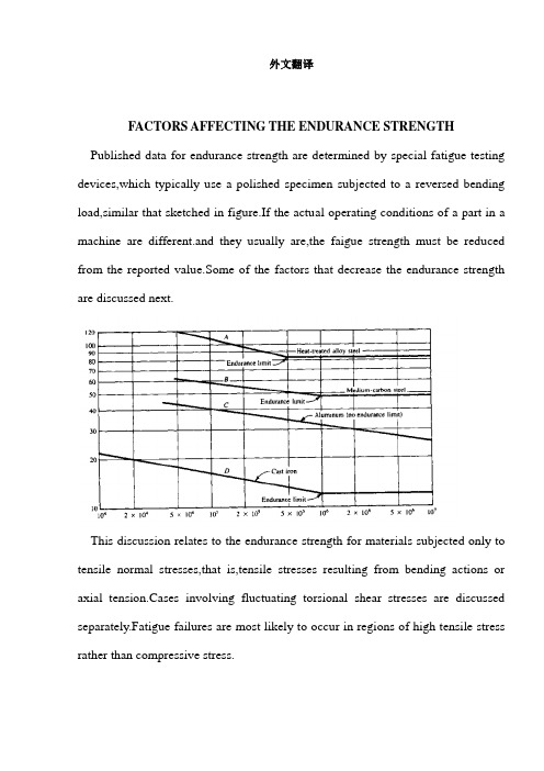
外文翻译FACTORS AFFECTING THE ENDURANCE STRENGTH Published data for endurance strength are determined by special fatigue testing devices,which typically use a polished specimen subjected to a reversed bending load,similar that sketched in figure.If the actual operating conditions of a part in a machine are different.and they usually are,the faigue strength must be reduced from the reported value.Some of the factors that decrease the endurance strength are discussed next.This discussion relates to the endurance strength for materials subjected only to tensile normal stresses,that is,tensile stresses resulting from bending actions or axial tension.Cases involving fluctuating torsional shear stresses are discussed separately.Fatigue failures are most likely to occur in regions of high tensile stress rather than compressive stress.Size of the sectionThe test specimen is usually 0.30 inch (7.6 mm)in rger section sizes exhibit lower strengths,have a less favorable stress distribution,and have less uniformity of properties,particularly with heat-treated parts.Reference 1 includes a suggested method of determing the size factor for rotating shafts up to 10.0 inches(250 mm)in diameter. We will use that method here also because we are basing our analysis on the reversed bending phenomenon.Table shows the suggested relationships for determing a size factor,to be applied to the endurance strength to account for the size of the cross section .Figure shows plots of the equations from Table,with some blending of the curves,Reading from the curves should provide acceptable accuracy.When the component being designed is not circular like a shaft,judgment is required to determine the characteristic dimension to use in the formulas.For flat,rolled shapes,the thickness should be used.Noted that the use of these equations is approximate.Surface FinishAny deviation from a polished surface reduces endurance strength.Figure shows rough estimates for the endurance strengths,compared with the ultimate tensile strength of steels for several practical surface conditions,It is critical that parts subjected to fatigue loading be protected from nicks,scratches,and corrosion because they drastically reduce fatigue strength.Stress ConcentrationsSudden changes in geometry ,especially sharp grooves and notches where high stress concentrations occur,are likely places for fatigue failures to occur.Care should be taken in the design and manufacture of cyclically loaded parts to keep stress concentration factors to a low value.We will apply the stress concentration factors ,as found from the methods of Section,to the computed stresses,rather than to the allowable strengths.FlawsInternal flaws of the material,especially likely in cast parts,are places in which fatigue cracks initiate.Critical parts can be inspected by x-ray techniques for internal flaws,If they are not inspected, a higher-than-average design factor should be specified for cast parts,and a lower endurance strength should be used.TemperatureMost materials have a lower endurances strength at high temperatures.The reported values are for room temperatures.Operation above 160°F(72°C) will reduce the endurance strength of most ductile materials.Nonuniform Material PropertiesMany materials have different material properties in different directions because of the manner in which the material was processed.Rolled sheet or bar products are typically stronger in the direction of rolling than they are in the transversedirection.Fatigue tests are likely have been run on test bars oriented in the stronger direction.Stressing of such material in the transverse direction may result in lower endurance strength.Nonuniform properties are also likely to exist in the vicinity of welds because of incomplete weld penetration,slag inclusions,and variations in the geometry of the part at the weld.Also.welding of heat-treated materials may alter the strength of the material because of local annealing near the weld.Some welding processes may result in th production of residual tensile stresses that decrease the effective endurance strength of the material.Annealing or normalizing after welding is often used to relieve these stresses,but the effect of such treatments on the strength of the base material must be considered.Residual StressesFatigue failures typically initiate at locations of relatively high tensile stress.Grinding and machining,especially with high material removal rates,also cause undesirable residual tensile stress.Welding has already been mentioned as a process that may produce residual tensile stress.Any manufacturing process that tends to produce residual stress will decrease the endurance strength of the component. Critical areas of cyclically loaded components should be machined or ground in a gentle fashion.Processes that produce residual compressive stresses can prove to be benefical.Shot blasting and peening are two such methods.Shot blasting is performed by directing a highvelocity stream of hardened balls or pellets at the surface to be treated.Peening uses a series of hammer blows on the surface.Crankshafts,springs,and other cyclically loaded machine parts can benefit from these methods.Corrosion and Environmental FactorsEndurance strength data are typically measured with the specimen in air.Operating conditions that expose a component to water,salt solutions,or other corrosive environments can significantly reduce the effective endurance strength.Corrosion may cause harmful local surface roughness and may also alter the internal grain structure and chemistry of ehe material.Steels exposed to hydrogen are especially affected adversely.NitridingNitriding is a surface-hardening process for alloy steels in which the material is heated to 950°F(514°C)in a nitrogen atmosphere,typically ammonia gas,followed by slow cooling.Impvovement of endurance strength of 50% or more can be achieved with nitriding.Wrought versus Cast MaterialsMetal alloys having similar chemical compositions can be either wrought or cast to produce the final form.Wrought materials are usually rolled or drawn.Wrought materials usually have a higher endurance strength than cast materials of similar composition in regions where no significant stress concentration exits.However,in the vicinity of notches and other discontinuities,the endurance strength of wrought and cast materials is more nearly equal.One possible explanation of this phenomenon is that the cast material is likely to have more isotropic material properties than the wrought material and is less affected by the presence of the stress concentration.To use the more conservative approach,it is recommended that a factor of 0.8 be applied to the basic endurance strength if a cast steel is used.For cast iron,a factor of 0.70 is recommended.Type of StressEndurance strength data are obtained from the rotating beam test that produces completely reversed and repeated normal stresses.The maximum stress isproducted at the surface of the specimen,and the stress vanes linearly to zero at the center of the circular cross section.If the actual loading is different from bending,a factor for the type of loading should be applied to the endurance strength.Axial TensionUnder pure tension, all of the material--not just the surface—is subjected to the maximum stress. A factor of 0.80 is suggested to be the bending endurance strength to reflect this different behavior.Effect of Stress Ratio on Endurance StrengthFigure 5-10 shows the general variation of endurance-strength data for a given material when the stress ratio R varies from -1.0 to +1.0,covering the range of cases including the following:■Repeated,reversed stress(Figure 5-3);R=-1.0■Partially reversed fluctuating stress with a tensile mean stress【Figure 5-4(b)】;-1.0 < R < 0■Repeated,one-direction tensile stress(Figure 5-6);R=0■Fluctuating tensile stress【Figure 5-4(a)】;0 < R < 1.0■Static stress(Figure 5-1);R=1Note that Figure 5-10 is only an example,and it should not be used to determine actual data points.If such data are desired for a particular material,specific data for that material must be found either experimentally or published literature.The most damaging kind of stress among those listed is the repeated,reversed stress with R=-1.(See Reference 2.page 27.)Recall that the rotating shaft in bending as shown in Figure 5-2 is an example of a load-carrying member subjected to a stress ratio R=-1.Fluctuating stresses with a compressive mean stress as shown in Parts(c) and (d)of Figure 5-4 do not significantly affect the endurance strength of the materialbecause fatigue failures tend to originate in regions of tensile stress.Note that the curves of Figure 5-10 show estimate of the endurance strength, Sn ,as a function of the ultimate tensile strength for steel.These data apply to ideal polished specimens and do not include any of ethe other factors discussed in this section. For example,the curve for R=-1.0(reversed bending)shows that the endurance strength for steel is approximately 0.5 times the ultimate strength(0.50×Sn)for large numbers of cycles of loading(approximately 10 or higher).This is a good general estimate for steels. The chart also shows that types of load producing R greater than -1.0 but less than 1.0 have less of an effect on the endurance strength. This illustrates that using data from the reversed bending test is the most conservative.We will not use Figure 5-10 directly for problem in this book because our procedure for estimating the actual endurance strength starts with the use of Figure 5-9 which presents data from reversed bending tests .Therefore,the effect of stress ratio is already included. Section 5-9 of this chapter includes methods of analysis for loading cases in which the fluctuating stress produces a stress ratio different from R=-1.0ReliabilityThe data for endurance strength for steel shown in Figure 5-9 represent average values derived from many tests of specimens having the appropriate ultimate strength and surface conditions.Naturally,there is variation among the data points;that is, half are higher and half are lower than the reported values on the givencurve.The curve,then ,represents a reliability of 50%,indicating that half of the parts would fail. Obviously, it is advisable to design for a higher reliability, say.90%,99%,or 99.9%.A factor can be used to estimate a lower endurance strength than can be used for design to produce the higher reliability values. Ideally,a statistical analysis of actual data for the material to be used in the design should be obtained.Reference 8 shows a method for analyzing such data.By making certain assumptions about the form of the distribution of strength data.Reference 8 also reports the values as approximate reliability factors,Cr. We will apply these factors to the average endurance strength.影响耐久性强度的因素耐力强度公布的数据是由特殊的疲劳试验装置测量出的,通常采用抛光试样遭受了反向弯曲载荷的形式,就像图中所描绘的。
机械设计制造及其自动化毕业论文中英文资料外文翻译
机械设计创造及其自动化毕业论文外文文献翻译INTEGRATION OF MACHINERY译文题目专业机械设计创造及其自动化外文资料翻译INTEGRATION OF MACHINERY(From ELECTRICAL AND MACHINERY INDUSTRY)ABSTRACTMachinery was the modern science and technology development inevitable result, this article has summarized the integration of machinery technology basic outline and the development background .Summarized the domestic and foreign integration of machinery technology present situation, has analyzed the integration of machinery technology trend of development.Key word: integration of machinery ,technology, present situation ,product t,echnique of manufacture ,trend of development0. Introduction modern science and technology unceasing development, impelled different discipline intersecting enormously with the seepage, has caused the project domain technological revolution and the transformation .In mechanical engineering domain, because the microelectronic technology and the computer technology rapid development and forms to the mechanical industry seepage the integration of machinery, caused the mechanical industry the technical structure, the product organization, the function and the constitution, the production method and the management systemof by machinery for the characteristic integration ofdevelopment phase.1. Integration of machinery outline integration of machinery is refers in the organization new owner function, the power function, in the information processing function and the control function introduces the electronic technology, unifies the system the mechanism and the computerization design and the software which constitutes always to call. The integration of machinery development also has become one to have until now own system new discipline, not only develops along with the science and technology, but also entrusts with the new content .But its basic characteristic may summarize is: The integration of machinery is embarks from the system viewpoint, synthesis community technologies and so on utilization mechanical technology, microelectronic technology, automatic control technology, computer technology, information technology, sensing observation and control technology, electric power electronic technology, connection technology, information conversion technology as well as software programming technology, according to the system function goal and the optimized organization goal, reasonable disposition and the layout various functions unit, in multi-purpose, high grade, redundant reliable, in the low energy consumption significance realize the specific function value, and causes the overall system optimization the systems engineering technology .From this produces functional system, then becomes an integration of machinery systematic or the integration of machinery product. Therefore, of coveringtechnology is based on the above community technology organic fusion one kind of comprehensive technology, but is not mechanical technical, the microelectronic technology as well as other new technical simple combination, pieces together .This is the integration of machinery and the machinery adds the machinery electrification which the electricity forms in the concept basic difference .The mechanical engineering technology has the merely technical to develop the machinery electrification, still was the traditional machinery, its main function still was replaces with the enlargement physical strength .But after develops the integration of machinery, micro electron installment besides may substitute for certain mechanical parts the original function, but also can entrust with many new functions,like the automatic detection, the automatic reduction information, demonstrate the record, the automatic control and the control automatic diagnosis and the protection automatically and so on .Not only namely the integration of machinery product is human's hand and body extending, human's sense organ and the brains look, has the intellectualized characteristic is the integration of machinery and the machinery electrification distinguishes in the function essence.2. Integration of machinery development condition integration of machinery development may divide into 3 stages roughly.20th century 60's before for the first stage, this stage is called the initial stage .In this time, the people determination not on own initiative uses the electronic technology the preliminary achievement to consummate the mechanical product the performance .Specially in Second World War period, the war has stimulated the mechanical product and the electronic technology union, these mechanical and electrical union military technology, postwar transfers civilly, to postwar economical restoration positive function .Developed and the development at that time generally speaking also is at the spontaneouscondition .Because at that time the electronic technology development not yet achieved certain level, mechanical technical and electronic technology union also not impossible widespread and thorough development, already developed the product was also unable to promote massively. The 20th century 70~80 ages for the second stage, may be called the vigorous development stage .This time, the computer technology, the control technology, the communication development, has laid the technology base for the integration of machinery development . Large-scale, ultra large scale integrated circuit and microcomputer swift and violent development, has provided the full material base for the integration of machinery development .This time characteristic is :①A mechatronics word first generally is accepted in Japan, probably obtains the quite widespread acknowledgment to 1980s last stages in the worldwide scale ;②The integration of machinery technology and the product obtained the enormous development ;③The various countries start to the integration of machinery technology and the product give the very big attention and the support. 1990s later periods, started the integration of machinery technology the new stagewhich makes great strides forward to the intellectualized direction, the integration of machinery enters the thorough development time .At the same time, optics, the communication and so on entered the integration of machinery, processes the technology also zhan to appear tiny in the integration of machinery the foot, appeared the light integration of machinery and the micro integration of machinery and so on the new branch; On the other hand to the integration of machinery system modeling design, the analysis and the integrated method, the integration of machinery discipline system and the trend of development has all conducted the thorough research .At the same time, because the hugeprogress which domains and so on artificial intelligence technology, neural network technology and optical fiber technology obtain, opened the development vast world for the integration of machinery technology .These research, will urge the integration of machinery further to establish the integrity the foundation and forms the integrity gradually the scientific system. Our country is only then starts from the beginning of 1980s in this aspect to study with the application .The State Councilsummary had considered fully on international the influence which and possibly brought from this about the integration of machinery technology developmenttrend .Many universities, colleges and institutes, the development facility and some large and middle scale enterprises have done the massive work to this technical development and the application, does not yield certain result, but and so on the advanced countries compared with Japan still has the suitable disparity.3. Integration of machinery trend of development integrations of machinery are the collection machinery, the electron, optics, the control, the computer, the information and so on the multi-disciplinary overlapping syntheses, its development and the progress rely on and promote the correlation technology development and the progress .Therefore, the integration of machinery main development direction is as follows:3.1 Intellectualized intellectualizations are 21st century integration of machinery technological development important development directions .Theartificial intelligence obtains day by day in the integration of machinery constructor's research takes, the robot and the numerical control engine bedis to the machine behavior description, is in the control theory foundation, the absorption artificial intelligence, the operations research, the computer science, the fuzzy mathematics, the psychology, the physiology and the chaos dynamics and so on the new thought, the new method, simulate the human intelligence, enable it to have abilities and so on judgment inference, logical thinking, independent decision-making, obtains the higher control goal in order to .Indeed, enable the integration of machinery product to have with the human identical intelligence, is not impossible, also is nonessential .But, the high performance, the high speed microprocessor enable the integration of machinery product to have preliminary intelligent or human's partial intelligences, then is completely possible and essential.In the modern manufacture process, the information has become the control manufacture industry the determining factor, moreover is the most active actuation factor .Enhances the manufacture system information-handling capacity to become the modern manufacture science development a key point .As a result of the manufacture system information organization and structure multi-level, makes the information the gain, the integration and the fusion presents draws up the character, information measure multi-dimensional, as well as information organization's multi-level .In the manufacture information structural model, manufacture information uniform restraint, dissemination processing and magnanimous data aspects and so on manufacture knowledge library management, all also wait for further break through.Each kind of artificial intelligence tool and the computation intelligence method promoted the manufacture intelligence development in the manufacture widespread application .A kind based on the biological evolution algorithm computation intelligent agent, in includes thescheduling problem in the combination optimization solution area of technology, receives the more and more universal attention, hopefully completes the combination optimization question when the manufacture the solution speed and the solution precision aspect breaks through the question scale in pairs the restriction .The manufacture intelligence also displays in: The intelligent dispatch, the intelligent design, the intelligent processing, the robot study, the intelligent control, the intelligent craft plan, the intelligent diagnosis and so on are various These question key breakthrough, may form the product innovation the basic research system. Between 2 modern mechanical engineering front science different science overlapping fusion will have the new science accumulation, the economical development and society's progress has had the new request and the expectation to the science and technology, thus will form the front science .The front science also has solved and between the solution scientific question border area .The front science has the obvious time domain, the domain and the dynamic characteristic .The project front science distinguished in the general basic science important characteristic is it has covered the key science and technology question which the project actual appeared.Manufacture system is a complex large-scale system, for satisfies the manufacture system agility, the fast response and fast reorganization ability, must profit from the information science, the life sciences and the social sciences and so on the multi-disciplinary research results, the exploration manufacture system new architecture, the manufacture pattern and the manufacture system effective operational mechanism .Makes the system optimization the organizational structure and the good movement condition is makes the system modeling , the simulation and the optimized essential target .Not only the manufacture system new architecture to makes the enterprise the agility and may reorganize ability to the demand response ability to have the vital significance, moreover to made the enterprise first floor production equipment the flexibility and may dynamic reorganization ability set a higher request .The biological manufacture view more and more many is introduced the manufacture system, satisfies the manufacture system new request.The study organizes and circulates method and technique of complicated system from the biological phenomenon, is a valid exit which will solve many hard nut to cracks that manufacturing industry face from now on currently .Imitating to living what manufacturing point is mimicry living creature organ of from the organization, from match more, from growth with from evolution etc. function structure and circulate mode of a kind of manufacturing system and manufacturing process.The manufacturing drives in the mechanism under, continuously by one's own perfect raise on organizing structure and circulating mode and thus to adapt the process of[with] ability for the environment .For from descend but the last product proceed together a design and make a craft rules the auto of the distance born, produce system of dynamic state reorganization and product and manufacturing the system tend automatically excellent provided theories foundation and carry out acondition .Imitate to living a manufacturing to belong to manufacturing science and life science of"the far good luck is miscellaneous to hand over", it will produce to the manufacturing industry for 21 centuries huge of influence .机电一体化摘要机电一体化是现代科学技术发展的必然结果,本文简述了机电一体化技术的基本概要和发展背景。
机械专业毕业论文外文翻译

附录一英文科技文献翻译英文原文:Experimental investigation of laser surface textured parallel thrust bearingsPerformance enhancements by laser surface texturing (LST) of parallel-thrust bearings is experimentally investigated. Testresults are compared with a theoretical model and good correlation is found over the relevant operating conditions. A compari-son of the performance of unidirectional and bi-directional partial-LST bearings with that of a baseline, untextured bearing ispresented showing the benefits of LST in terms of increased clearance and reduced friction.KEY WORDS: fluid film bearings, slider bearings, surface texturing1. IntroductionThe classical theory of hydrodynamic lubrication yields linear (Couette) velocity distribution with zero pressure gradients between smooth parallel surfaces under steady-state sliding. This results in an unstable hydrodynamic film that would collapse under any external force acting normal to the surfaces. However, experience shows that stable lubricating films can deve lop between parallel sliding surfaces, generally because of some mechanism that relaxes one or more of the assumptions of the classical theory.A stable fluid film with sufficient load-carrying capacity in parallel sliding surfaces can be obtained, for example, with macro or micro surface structure of different types. These include waviness [1] and protruding microasperities [2–4]. A good literature review on the subject can be found in Ref. [5]. More recently, laser surface texturing (LST) [6–8], as well as inlet roughening by longitudinal or transverse grooves [9] were suggested to provide load capacity in parallel sliding. The inlet roughness concept of Tonder [9] is based on ‘‘effective clearance’’ reduction in the sliding direction and in this respect it is identical to the par- tial-LST concept described in ref.[10] for generating hydrostatic effect in high-pressure mechanical seals.Very recently Wang et al. [11] demonstrated experimentally a doubling of the load-carrying capacity for the surface- texture design by reactive ion etching of SiCparallel-thrust bearings sliding in water. These simple parallel thrust bearings are usually found in seal-less pumps where the pumped fluid is used as the lubricant for the bearings. Due to the parallel sliding their performance is poorer than more sophisticated tapered or stepped bearings. Brizmer et al. [12] demon-strated the potential of laser surface texturing in the form of regular micro-dimples for providing load-carrying capacity with parallel-thrust bearings. A model of a textured parallelslider was developed and the effect of surface texturing on load-carrying capacitywas analyzed. The optimum parameters of the dimples were found in order to obtainmaximum load-carrying capacity. A micro-dimple ‘‘collective effect’’ was identi-fied that is capable of generating substantial load-carrying capacity, approaching that of optimumconventional thrust bearings. The purpose of the present paper is to investigate experimentally the validity of the model described in Ref. [12] by testing practical thrust bearings and comparing the performance of LST bearings with that of the theoretical predictions and with the performance of standard non-textured bearings2. BackgroundA cross section of the basic model that was analyzed in Ref. [12] is shown in figure1. A slider having a width B is partially textured over a portion Bp =αB of its width.The textured surface consists of multiple dimples with a diameter,depth and area density Sp. As a result of the hydrodynamic pressure generated by the dimples the sliding surfaces will be separated by a clearance depending on the sliding velocity U, the fluid viscosity l and the external load It was found in Ref. [12] that an optimum ratio exists for the parameter that provides maximum dimensionless load-carrying capacity where L isthe bearing length, and this optimum value is hp=1.25. It was further found in Ref. [12] that an optimum value exists for the textured portion a depending onthe bearing aspect ratio L/B. This behavior is shown in figure 2 for a bearing with L/B = 0.75 at various values of the area density Sp. As can be seen in the range of Sp values from 0.18 to 0.72 the optimum a value varies from 0.7 to 0.55, respectively. It can also be seen from figure 2 that for a < 0.85 no optimum value exists for Sp and the maximum load W increases with increasing Sp. Hence, the largest area density that can be practically obtained with the laser texturing is desired. It is also interesting to note from figure 2 the advantage of partial-LST (a < 1) over the full LST (a = 1) for bearing applications. At Sp= 0.5, for example, the load W at a = 0.6 is about three times higher than its value at a = 1. A full account of this behavior is given in Ref. [12].3. ExperimentalThe tested bearings consist of sintered SiC disks 10 mm thick, having 85 mm outer diameter and 40 mm inner diameter. Each bearing (see figure 3) comprises a flat rotor (a) and a six-pad stator (b). The bearings were provided with an original surface finish by lapping to a roughness average Ra= 0.03 lm. Each pad has an aspect ratio of 0.75 when its width is measured along the mean diameter of the stator. The photographs of two partial-LST stators are shown in figure 4 where the textured areas appear as brighter matt surfaces. The first stator indicated (a) is a unidirectional bearing with the partial-LST adjacent to the leading edge of each pad, similar to the model shown in figure 1. The second stator (b) is a bi-directional version of a partial-LST bearing having two equal textured portions, a/2, on each of the pad ends. The laser texturing parameters were the following; dimple depth, dimplediameter and dimple area density Sp= 0.60.03. These dimple dimensions were obtained with 4 pulses of 30 ns duration and 4 mJ each using a 5 kHz pulsating Nd:YAG laser. The textured portion of the unidirectional bearing was a= 0.73 and that of the bi-directional bearing was a= 0.63. As can be seen from figure 2 both these a values should produce load-carrying capacity vary close to the maximum theoret ical value.The test rig is shown schematically in figure 5. An electrical motor turns a spindle to which an upper holder of the rotor is attached. A second lower holder of the stator is fixed to a housing, which rests on a journal bearing and an axial loading mechanism that can freely move in the axial direction. An arm that presses against a load cell and thereby permits friction torque measurements prevents the free rotation of this housing. Axial loading is provided by means of dead weights on a lever and is measured with a second load cell. A proximity probe that is attached to the lower holder of the stator allows on-line measurements of the clearance change between rotor and stator as the hydrodynamiceffects cause axial movement of the housing to which the stator holder is fixed. Tapwater is supplied by gravity from a large tank to the center of the bearing and the leakage from the bearing is collected and re-circulated. A thermocouple adjacent to the outer diameter of the bearing allows monitoring of the water temperature as the water exit the bearing. A PC is used to collect and process data on-line. Hence,theinstantaneous clearance, friction coefficient, bearing speed and exit water temperaturecan be monitored constantly.The test protocol incl udes identifying a reference “zero〞point for the clearance measurements by first loading and then unloading a stationary bearing over the full load range. Then the lowest axial load is applied, the water supply valve is opened and the motor turned on. Axial loading is increased by steps of 40 N and each load step is maintained for 5 min following the stabilization of the friction coefficient ata steady-state value. The bearing speed and water temperature are monitored throughout the test for any irregularities. The test ends when a maximum axial load of 460 N is reached or if the friction coefficient exceeds a value of 0.35. At the end ofthe last load step the motor and water supply are turned off and the reference for the clearance measurements is rechecked. Tests are performed at two speeds of 1500and 3000 rpm corresponding to average sliding velocities of 4.9 and 9.8 m/s, respectively and each test is repeated at least three times.4. Results and discussionAs a first step the validity of the theoretical mode l in Ref. [12] was examined by comparing the theoretical and experimental results of bearing clearance versus bearing load for a unidirectional partial-LST bearing. The results are shown in figure 6 for the two speeds of 1500 and 3000 rpm where the solid and dashed lines correspond to the model and experiment, respectively. As can be seen, the agreement between the model and the experiment is good, with differences of less than 10%, aslong as the load is above 150 N. At lower loads the measured experimental clearances are much larger than the model predictions, particularly at the higher speed of 3000 rpm where at 120 N the measured clearance is 20 lm, which is about 60% higher than the predicted value. It turns out that the combination of such large clearances and relatively low viscosity of the water may result in turbulent fluid film. Hence, the assumption of laminar flow on which the solution of the Reynolds equation in Ref.[12] is based may be violated making the model invalid especially at the higher speed and lowest load. In order to be consistent with the model of Ref. [12] it was decided to limit further comparisons to loads above 150 N.It should be noted here that the first attempts to test the baseline untextured bearing with the original surface finish of Ra= 0.03 lm on both the stator and rotor failed due to extremely high friction even at the lower loads. On the other hand the partial-LST bearing ran smoothly throughout the load range. It was found that the post-LST lapping to completely remove about 2 lm height bulges, which are formed during texturing around the rims of the dimples, resulted in a slightly rougher surface with Ra= 0.04 lm. Hence, the baseline untextured stator was also lapped to the same rough- ness of the partial-LST stator and all subsequent tests were performed with the same Ra value of 0.04 lm for all the tested stators. The rotor surface roughnessand 2.2 lm for the LST and untextured bearings, respectively. As can be seen from figure 7 this ratio of about 3 in favor of the partial-LST bearing is maintained over the entire load range.Figure 8 presents the results for the bi-directionalbearing (see stator in figure 4(b)). In this case the LST parameters are Sp ¼ 0:614 and a ¼ 0:633. The clearances of the bi-directional partial-LST bearing are lower compared to these of the unidirectional bearing at the same load. At 460 N load the clearance for the 1500 rpm is 4.1 lm and for the 3000 rpm it is 6 lm. These values represent a reduction of clearance between 33 and 10% compared to the unidirectional case. However, as can be seen from figure 8 the performance of the partial-LST bi-directional bearing is still substantially better than that of the untextured bearing.The friction coefficient of partial-LST unidirectional and bi-directional bearings was compared with that of the untextured bearing in figures 9 and 10 for the two speeds of 1500 and 3000 rpm, respectively. As can be seen the friction coefficient of the two partial-LST bearings is very similar with slightly lower values in the case of the more efficient unidirectional bearing. The friction coefficient of the untextured bearing is much larger compared to that of the LST bearings. At 1500 rpm (figure 9) and the highest load of 460 N the friction coefficient of the untextured bearing is about 0.025 compared to about 0.01 for the LST bearings.At the lowest load of 160 N the values are about 0.06 for the untextured bearing and around 0.02 for the LST bearings. Hence, the friction values of the untextured bearing are between 2.5 and 3 times higher than the corresponding values for the partial-LST bearings over the entire load range. Similar results were obtained at the velocity of3000 rpm (figure 10) but the level of the friction coefficients is somewhat higherdue to the higher speed. The much higher friction of the untextured bearing is due to the much smaller clearances of this bearing (see figures 7 and 8) that result in higher viscous shear.Bearings fail for a number of reasons,but the most common are misapplication,contamination,improper lubricant,shipping or handling damage,and misalignment. The problem is often not difficult to diagnose because a failed bearing usually leaves telltale signs about what went wrong.However,while a postmortem yields good information,it is better to avoid the process altogether by specifying the bearing correctly in The first place.To do this,it is useful to review the manufacturers sizing guidelines and operating characteristics for the selected bearing.Equally critical is a study of requirements for noise, torque, and runout, as well as possible exposure to contaminants, hostile liquids, and temperature extremes. This can provide further clues as to whether a bearing is right for a job.1 Why bearings failAbout 40% of ball bearing failures are caused by contamination from dust, dirt, shavings, and corrosion. Contamination also causes torque and noise problems, and is often the result of improper handling or the application environment.Fortunately, a bearing failure caused by environment or handling contamination is preventable,and a simple visual examination can easily identify the cause.Conducting a postmortem il1ustrates what to look for on a failed or failing bearing.Then,understanding the mechanism behind the failure, such as brinelling or fatigue, helps eliminate the source of the problem.Brinelling is one type of bearing failure easily avoided by proper handing and assembly. It is characterized by indentations in the bearing raceway caused by shock loading-such as when a bearing is dropped-or incorrect assembly. Brinelling usually occurs when loads exceed the material yield point(350,000 psi in SAE 52100 chrome steel).It may also be caused by improper assembly, Which places a load across the races.Raceway dents also produce noise,vibration,and increased torque.A similar defect is a pattern of elliptical dents caused by balls vibrating between raceways while the bearing is not turning.This problem is called false brinelling. It occurs on equipment in transit or that vibrates when not in operation. In addition, debris created by false brinelling acts like an abrasive, further contaminating the bearing. Unlike brinelling, false binelling is often indicated by a reddish color from fretting corrosion in the lubricant.False brinelling is prevented by eliminating vibration sources and keeping the bearing well lubricated. Isolation pads on the equipment or a separate foundation may be required to reduce environmental vibration. Also a light preload on the bearing helps keep the balls and raceway in tight contact. Preloading also helps prevent false brinelling during transit.Seizures can be caused by a lack of internal clearance, improper lubrication, orexcessive loading. Before seizing, excessive, friction and heat softens the bearing steel. Overheated bearings often change color,usually to blue-black or straw colored.Friction also causes stress in the retainer,which can break and hasten bearing failure.Premature material fatigue is caused by a high load or excessive preload.When these conditions are unavoidable,bearing life should be carefully calculated so that a maintenance scheme can be worked out.Another solution for fighting premature fatigue is changing material.When standard bearing materials,such as 440C or SAE 52100,do not guarantee sufficient life,specialty materials can be recommended. In addition,when the problem is traced back to excessive loading,a higher capacity bearing or different configuration may be used.Creep is less common than premature fatigue.In bearings.it is caused by excessive clearance between bore and shaft that allows the bore to rotate on the shaft.Creep can be expensive because it causes damage to other components in addition to the bearing.0ther more likely creep indicators are scratches,scuff marks,or discoloration to shaft and bore.To prevent creep damage,the bearing housing and shaft fittings should be visually checked.Misalignment is related to creep in that it is mounting related.If races are misaligned or cocked.The balls track in a noncircumferencial path.The problem is incorrect mounting or tolerancing,or insufficient squareness of the bearing mounting site.Misalignment of more than 1/4·can cause an early failure.Contaminated lubricant is often more difficult to detect than misalignment or creep.Contamination shows as premature wear.Solid contaminants become an abrasive in the lubricant.In addition。
机械制造工艺外文文献翻译、中英文翻译、外文翻译
中国地质大学长城学院本科毕业设计外文资料翻译系别:工程技术系专业:机械设计制造及其自动化姓名:侯亮学号:052115072015年 4 月 3 日外文资料翻译原文Introduction of MachiningHave a shape as a processing method, all machining process for the production of the most commonly used and most important method. Machining process is a process generated shape, in this process, Drivers device on the work piece material to be in the form of chip removal. Although in some occasions, the workpiece under no circumstances, the use of mobile equipment to the processing, However, the majority of the machining is not only supporting the workpiece also supporting tools and equipment to complete.Machining know the process has two aspects. Small group of low-cost production. For casting, forging and machining pressure, every production of a specific shape of the workpiece, even a spare parts, almost have to spend the high cost of processing. Welding to rely on the shape of the structure, to a large extent, depend on effective in the form of raw materials. In general, through the use of expensive equipment and without special processing conditions, can be almost any type of raw materials, mechanical processing to convert the raw materials processed into the arbitrary shape of the structure, as long as the external dimensions large enough, it is possible. Because of a production of spare parts, even when the parts and structure of the production batch sizes are suitable for the original casting, Forging or pressure processing to produce, but usually prefer machining.Strict precision and good surface finish, machining the second purpose is the establishment of the high precision and surface finish possible on the basis of. Many parts, if any other means of production belonging to the large-scale production, Well Machining is a low-tolerance and can meet the requirements of small batch production. Besides, many parts on the production and processing of coarse process to improve its general shape of the surface. It is only necessary precision and choose only the surface machining. For instance, thread, in addition to mechanical processing, almost no other processing method for processing. Another example is the blacksmith pieces keyhole processing, as well as training to be conducted immediately after the mechanical completion of the processing.Primary Cutting ParametersCutting the work piece and tool based on the basic relationship between the following four elements to fully describe : the tool geometry, cutting speed, feed rate, depth and penetration of a cutting tool.Cutting Tools must be of a suitable material to manufacture, it must be strong, tough, hard and wear-resistant. Tool geometry -- to the tip plane and cutter angle characteristics -- for each cutting process must be correct.Cutting speed is the cutting edge of work piece surface rate, it is inches per minute toshow. In order to effectively processing, and cutting speed must adapt to the level of specific parts -- with knives. Generally, the more hard work piece material, the lower the rate.Progressive Tool to speed is cut into the work piece speed. If the work piece or tool for rotating movement, feed rate per round over the number of inches to the measurement. When the work piece or tool for reciprocating movement and feed rate on each trip through the measurement of inches. Generally, in other conditions, feed rate and cutting speed is inversely proportional to.Depth of penetration of a cutting tool -- to inches dollars -- is the tool to the work piece distance. Rotary cutting it to the chip or equal to the width of the linear cutting chip thickness. Rough than finishing, deeper penetration of a cutting tool depth.Rough machining and finishing machiningThere are two kinds of cuts in machine- shop work called, respectively, the "roughing cut" and the "finishing cut". When a piece is "roughed out", it is quite near the shape and size required, but enough metal has been left on the surface to finish smooth and to exact size." Generally speaking, bars of steel, forging, castings, etc. are machined to the required shape and size with only one roughing and one finishing cut. Sometimes, however, certain portions of a piece may require more than one roughing cut. Also, in some jobs, for example, when great accuracy is not needed, or when a comparatively small amount of metal must be removed, a finishing cut may be all that is required. The roughing cut, to remove the greater part of the excess material, should be reasonably heavy, that is, all the machine, or cutting tool, or work, or all three, will stand. So the machinist’s purpose is to remove the excess stock as fast as he can without leaving, at the same time, a surface too torn and rough, without bending the piece if it is slender, and without spoiling the centers. The finishing cut, to make the work smooth and accurate, is a finer cut. The emphasis here is refinement - very sharp tool, comparatively little metal removed, and a higher degree of accuracy in measurement. Whether roughing or finishing, the machinist must set the machine for the given job. He must consider the size and shape of the work and the kind of material, also the kind of tool used and the nature of the cut to be made, then he proceeds to set the machine for the correct speed and feed and to set the tool to take the depth of cut desired.Automatic Fixture Design外文资料翻译译文机械制造工艺机械加工是所有制造过程中最普遍使用的而且是最重要的方法。
机械 外文翻译 外文文献 英文文献 轴承的摩擦与润滑
外文文献原文文章出处:/wenku/201104/05/147898.htmlFriction , Lubrication of BearingIn many of the problem thus far , the student has been asked to disregard or neglect friction . Actually , friction is present to some degree whenever two parts are in contact and move on each other. The term friction refers to the resistance of two or more parts to movement.Friction is harmful or valuable depending upon where it occurs. friction is necessary for fastening devices such as screws and rivets which depend upon friction to hold the fastener and the parts together. Belt drivers, brakes, and tires are additional applications where friction is necessary.The friction of moving parts in a machine is harmful because it reduces the mechanical advantage of the device. The heat produced by friction is lost energy because no work takes place. Also , greater power is required to overcome the increased friction. Heat is destructive in that it causes expansion. Expansion may cause a bearing or sliding surface to fit tighter. If a great enough pressure builds up because made from low temperature materials may melt.There are three types of friction which must be overcome in moving parts: (1)starting, (2)sliding, and(3)rolling. Starting friction is the friction between two solids that tend to resist movement. When two parts are at a state of rest, the surface irregularities of both parts tend to interlock and form a wedging action. T o produce motion in these parts, the wedge-shaped peaks and valleys of the stationary surfaces must be made to slide out and over each other. The rougher the two surfaces, the greater is starting friction resulting from their movement .Since there is usually no fixed pattern between the peaks and valleys of two mating parts, the irregularities do not interlock once the parts are in motion but slide over each other. The friction of the two surfaces is known as sliding friction. As shown in figure ,starting friction is always greater than sliding friction .Rolling friction occurs when roller devces are subjected to tremendous stress which cause the parts to change shape or deform. Under these conditions, the material in front of a roller tends to pile up and forces the object to roll slightly uphill. This changing of shape , known as deformation, causes a movement of molecules. As a result ,heat is produced from the added energy required to keep the parts turning and overcome friction.The friction caused by the wedging action of surface irregularities can be overcome partly by the precision machining of the surfaces. However, even these smooth surfaces may require the useof a substance between them to reduce the friction still more. This substance is usually a lubricant which provides a fine, thin oil film. The film keeps the surfaces apart and prevents the cohesive forces of the surfaces from coming in close contact and producing heat .Another way to reduce friction is to use different materials for the bearing surfaces and rotating parts. This explains why bronze bearings, soft alloys, and copper and tin iolite bearings are used with both soft and hardened steel shaft. The iolite bearing is porous. Thus, when the bearing is dipped in oil, capillary action carries the oil through the spaces of the bearing. This type of bearing carries its own lubricant to the points where the pressures are the greatest.Moving parts are lubricated to reduce friction, wear, and heat. The most commonly used lubricants are oils, greases, and graphite compounds. Each lubricant serves a different purpose. The conditions under which two moving surfaces are to work determine the type of lubricant to be used and the system selected for distributing the lubricant.On slow moving parts with a minimum of pressure, an oil groove is usually sufficient to distribute the required quantity of lubricant to the surfaces moving on each other .A second common method of lubrication is the splash system in which parts moving in a reservoir of lubricant pick up sufficient oil which is then distributed to all moving parts during each cycle. This system is used in the crankcase of lawn-mower engines to lubricate the crankshaft, connecting rod ,and parts of the piston.A lubrication system commonly used in industrial plants is the pressure system. In this system, a pump on a machine carries the lubricant to all of the bearing surfaces at a constant rate and quantity.There are numerous other systems of lubrication and a considerable number of lubricants available for any given set of operating conditions. Modern industry pays greater attention to the use of the proper lubricants than at previous time because of the increased speeds, pressures, and operating demands placed on equipment and devices.Although one of the main purposes of lubrication is reduce friction, any substance-liquid , solid , or gaseous-capable of controlling friction and wear between sliding surfaces can be classed as a lubricant.V arieties of lubricationUnlubricated sliding. Metals that have been carefully treated to remove all foreign materials seize and weld to one another when slid together. In the absence of such a high degree of cleanliness, adsorbed gases, water vapor ,oxides, and contaminants reduce frictio9n and thetendency to seize but usual ly result in severe wear; this is called “unlubricated ”or dry sliding.Fluid-film lubrication. Interposing a fluid film that completely separates the sliding surfaces results in fluid-film lubrication. The fluid may be introduced intentionally as the oil in the main bearing of an automobile, or unintentionally, as in the case of water between a smooth tuber tire and a wet pavement. Although the fluid is usually a liquid such as oil, water, and a wide range of other materials, it may also be a gas. The gas most commonly employed is air.Boundary lubrication. A condition that lies between unlubricated sliding and fluid-film lubrication is referred to as boundary lubrication, also defined as that condition of lubrication in which the friction between surfaces is determined by the properties of the surfaces and properties of the lubricant other than viscosity. Boundary lubrication encompasses a significant portion of lubrication phenomena and commonly occurs during the starting and stopping off machines.Solid lubrication. Solid such as graphite and molybdenum disulfide are widely used when normal lubricants do not possess sufficient resistance to load or temperature extremes. But lubricants need not take only such familiar forms as fats, powders, and gases; even some metals commonly serve as sliding surfaces in some sophisticated machines.Function of lubricantsAlthough a lubricant primarily controls friction and ordinarily does perform numerous other functions, which vary with the application and usually are interrelated .Friction control. The amount and character of the lubricant made available to sliding surfaces have a profound effect upon the friction that is encountered. For example, disregarding such related factors as heat and wear but considering friction alone between the same surfaces with on lubricant. Under fluid-film conditions, friction is encountered. In a great range of viscosities and thus can satisfy a broad spectrum of functional requirements. Under boundary lubrication conditions , the effect of viscosity on friction becomes less significant than the chemical nature of the lubricant.Wear control. wear occurs on lubricated surfaces by abrasion, corrosion ,and solid-to-solid contact wear by providing a film that increases the distance between the sliding surfaces ,thereby lessening the damage by abrasive contaminants and surface asperities.Temperature control. Lubricants assist in controlling corrosion of the surfaces themselves istwofold. When machinery is idle, the lubricant acts as a preservative. When machinery is in use, the lubricant controls corrosion by coating lubricated parts with a protective film that may contain additives to neutralize corrosive materials. The ability of a lubricant to control corrosion is directly relatly to the thickness of the lubricant film remaining on the metal surfaces and the chermical composition of the lubricant.Other functionsLubrication are frequently used for purposes other than the reduction of friction. Some of these applications are described below.Power transmission. Lubricants are widely employed as hydraulic fluids in fluid transmission devices.Insulation. In specialized applications such as transformers and switchgear , lubricants with high dielectric constants acts as electrical insulators. For maximum insulating properties, a lubricant must be kept free of contaminants and water.Shock dampening. Lubricants act as shock-dampening fluids in energy transferring devices such as shock absorbers and around machine parts such as gears that are subjected to high intermittent loads.Sealing. Lubricating grease frequently performs the special function of forming a seal to retain lubricants or to exclude contaminants.The object of lubrication is to reduce friction ,wear , and heating of machine pars which move relative to each other. A lubricant is any substance which, when inserted between the moving surfaces, accomplishes these purposes. Most lubricants are liquids(such as mineral oil, silicone fluids, and water),but they may be solid for use in dry bearings, greases for use in rolling element bearing, or gases(such as air) for use in gas bearings. The physical and chemical interaction between the lubricant and lubricating surfaces must be understood in order to provide the machine elements with satisfactory life.The understanding of boundary lubrication is normally attributed to hardy and doubleday , who found the extrememly thin films adhering to surfaces were often sufficient to assist relative sliding. They concluded that under such circumstances the chemical composition of fluid is important, and they introduced the term “boundary lubrication”. Boundary lubrication is at theopposite end of the spectrum from hydrodynamic lubrication.Five distinct of forms of lubrication that may be defined :(a) hydrodynamic;(b)hydrostatic;(c)elastohydrodynamic (d)boundary; (e)solid film.Hydrodynamic lubrication means that the load-carrying surfaces of the bearing are separated by a relatively thick film of lubricant, so as to prevent metal contact, and that the stability thus obtained can be explained by the laws of the lubricant under pressure ,though it may be; but it does require the existence of an adequate supply at all times. The film pressure is created by the moving surfaces itself pulling the lubricant under pressure, though it maybe. The film pressure is created by the moving surface to creat the pressure necessary to separate the surfaces against the load on the bearing . hydrodynamic lubrication is also called full film ,or fluid lubrication .Hydrostatic lubrication is obtained by introducing the lubricant ,which is sometime air or water ,into the load-bearing area at a pressure high enough to separate the surface with a relatively thick film of lubricant. So ,unlike hydrodynanmic lubrication, motion of one surface relative to another is not required .Elasohydrodynamic lubrication is the phenomenon that occurs when a lubricant is introduced between surfaces which are in rolling contact, such as mating gears or rolling bearings. The mathematical explanation requires the hertzian theory of contact stress and fluid mechanics.When bearing must be operated at exetreme temperatures, a solid film lubricant such as graphite or molybdenum disulfide must be use used because the ordinary mineral oils are not satisfactory. Must research is currently being carried out in an effort, too, to find composite bearing materials with low wear rates as well as small frictional coefficients.In a journal bearing, a shaft rotates or oscillates within the bearing , and the relative motion is sliding . in an antifriction bearing, the main relative motion is rolling . a follower may either roll or slide on the cam. Gear teeth mate with each other by a combination of rolling and sliding . pistions slide within their cylinders. All these applications require lubrication to reduce friction ,wear, and heating.The field of application for journal bearing s is immense. The crankshaft and connecting rod bearings of an automotive engine must poerate for thousands of miles at high temperatures and under varying load conditions . the journal bearings used in the steam turbines of power generating station is said to have reliabilities approaching 100 percent. At the other extreme there arethousands of applications in which the loads are light and the service relatively unimportant. a simple ,easily installed bearing is required ,suing little or no lubrication. In such cases an antifriction bearing might be a poor answer because because of the cost, the close ,the radial space required ,or the increased inertial effects. Recent metallurgy developments in bearing materials , combined with increased knowledge of the lubrication process, now make it possible to design journal bearings with satisfactory lives and very good reliabilities.中文译文轴承的摩擦与润滑现在看来,有很多这种情况,许多学生在被问到关于摩擦的问题时,往往都没引起足够的重视,甚至是忽视它。
- 1、下载文档前请自行甄别文档内容的完整性,平台不提供额外的编辑、内容补充、找答案等附加服务。
- 2、"仅部分预览"的文档,不可在线预览部分如存在完整性等问题,可反馈申请退款(可完整预览的文档不适用该条件!)。
- 3、如文档侵犯您的权益,请联系客服反馈,我们会尽快为您处理(人工客服工作时间:9:00-18:30)。
如何延长轴承寿命摘要:自然界苛刻的工作条件会导致轴承的失效,但是如果遵循一些简单的规则,轴承正常运转的机会是能够被提高的。
在轴承的使用过程当中,过分的忽视会导致轴承的过热现象,也可能使轴承不能够再被使用,甚至完全的破坏。
但是一个被损坏的轴承,会留下它为什么被损坏的线索。
通过一些细致的侦察工作,我们可以采取行动来避免轴承的再次失效。
关键词:轴承失效寿命导致轴承失效的原因很多,但常见的是不正确的使用、污染、润滑剂使用不当、装卸或搬运时的损伤及安装误差等。
诊断失效的原因并不困难,因为根据轴承上留下的痕迹可以确定轴承失效的原因。
然而,当事后的调查分析提供出宝贵的信息时,最好首先通过正确地选定轴承来完全避免失效的发生。
为了做到这一点,再考察一下制造厂商的尺寸定位指南和所选轴承的使用特点是非常重要的。
1 轴承失效的原因在球轴承的失效中约有40%是由灰尘、脏物、碎屑的污染以及腐蚀造成的。
污染通常是由不正确的使用和不良的使用环境造成的,它还会引起扭矩和噪声的问题。
由环境和污染所产生的轴承失效是可以预防的,而且通过简单的肉眼观察是可以确定产生这类失效的原因。
通过失效后的分析可以得知对已经失效的或将要失效的轴承应该在哪些方面进行查看。
弄清诸如剥蚀和疲劳破坏一类失效的机理,有助于消除问题的根源。
只要使用和安装合理,轴承的剥蚀是容易避免的。
剥蚀的特征是在轴承圈滚道上留有由冲击载荷或不正确的安装产生的压痕。
剥蚀通常是在载荷超过材料屈服极限时发生的。
如果安装不正确从而使某一载荷横穿轴承圈也会产生剥蚀。
轴承圈上的压坑还会产生噪声、振动和附加扭矩。
类似的一种缺陷是当轴承不旋转时由于滚珠在轴承圈间振动而产生的椭圆形压痕。
这种破坏称为低荷振蚀。
这种破坏在运输中的设备和不工作时仍振动的设备中都会产生。
此外,低荷振蚀产生的碎屑的作用就象磨粒一样,会进一步损害轴承。
与剥蚀不同,低荷振蚀的特征通常是由于微振磨损腐蚀在润滑剂中会产生淡红色。
消除振动源并保持良好的轴承润滑可以防止低荷振蚀。
给设备加隔离垫或对底座进行隔离可以减轻环境的振动。
另外在轴承上加一个较小的预载荷不仅有助于滚珠和轴承圈保持紧密的接触,并且对防止在设备运输中产生的低荷振蚀也有帮助。
造成轴承卡住的原因是缺少内隙、润滑不当和载荷过大。
在卡住之前,过大的摩擦和热量使轴承钢软化。
过热的轴承通常会改变颜色,一般会变成蓝黑色或淡黄色。
摩擦还会使保持架受力,这会破坏支承架,并加速轴承的失效。
材料过早出现疲劳破坏是由重载后过大的预载引起的。
如果这些条件不可避免,就应仔细计算轴承寿命,以制定一个维护计划。
另一个解决办法是更换材料。
若标准的轴承材料不能保证足够的轴承寿命,就应当采用特殊的材料。
另外,如果这个问题是由于载荷过大造成的,就应该采用抗载能力更强或其他结构的轴承。
蠕动不象过早疲劳那样普遍。
轴承的蠕动是由于轴和内圈之间的间隙过大造成的。
蠕动的害处很大,它不仅损害轴承,也破坏其他零件。
蠕动的明显特征是划痕、擦痕或轴与内圈的颜色变化。
为了防止蠕动,应该先用肉眼检查一下轴承箱件和轴的配件。
蠕动与安装不正有关。
如果轴承圈不正或翘起,滚珠将沿着一个非圆周轨道运动。
这个问题是由于安装不正确或公差不正确或轴承安装现场的垂直度不够造成的。
如果偏斜超过0.25°,轴承就会过早地失效。
检查润滑剂的污染比检查装配不正或蠕动要困难得多。
污染的特征是使轴承过早的出现磨损。
润滑剂中的固体杂质就象磨粒一样。
如果滚珠和保持架之间润滑不良也会磨损并削弱保持架。
在这种情况下,润滑对于完全加工形式的保持架来说是至关重要的。
相比之下,带状或冠状保持架能较容易地使润滑剂到达全部表面。
锈是湿气污染的一种形式,它的出现常常表明材料选择不当。
如果某一材料经检验适合工作要求,那么防止生锈的最简单的方法是给轴承包装起来,直到安装使用时才打开包装。
2 避免失效的方法解决轴承失效问题的最好办法就是避免失效发生。
这可以在选用过程中通过考虑关键性能特征来实现。
这些特征包括噪声、起动和运转扭矩、刚性、非重复性振摆以及径向和轴向间隙。
扭矩要求是由润滑剂、保持架、轴承圈质量(弯曲部分的圆度和表面加工质量)以及是否使用密封或遮护装置来决定。
润滑剂的粘度必须认真加以选择,因为不适宜的润滑剂会产生过大的扭矩,这在小型轴承中尤其如此。
另外,不同的润滑剂的噪声特性也不一样。
举例来说,润滑脂产生的噪声比润滑油大一些。
因此,要根据不同的用途来选用润滑剂。
在轴承转动过程中,如果内圈和外圈之间存在一个随机的偏心距,就会产生与凸轮运动非常相似的非重复性振摆(NRR)。
保持架的尺寸误差和轴承圈与滚珠的偏心都会引起NRR。
和重复性振摆不同的是,NRR是没有办法进行补偿的。
在工业中一般是根据具体的应用来选择不同类型和精度等级的轴承。
例如,当要求振摆最小时,轴承的非重复性振摆不能超过0.3微米。
同样,机床主轴只能容许最小的振摆,以保证切削精度。
因此在机床的应用中应该使用非重复性振摆较小的轴承。
在许多工业产品中,污染是不可避免的,因此常用密封或遮护装置来保护轴承,使其免受灰尘或脏物的侵蚀。
但是,由于轴承内外圈的运动,使轴承的密封不可能达到完美的程度,因此润滑油的泄漏和污染始终是一个未能解决的问题。
一旦轴承受到污染,润滑剂就要变质,运行噪声也随之变大。
如果轴承过热,它将会卡住。
当污染物处于滚珠和轴承圈之间时,其作用和金属表面之间的磨粒一样,会使轴承磨损。
采用密封和遮护装置来挡开脏物是控制污染的一种方法。
噪声是反映轴承质量的一个指标。
轴承的性能可以用不同的噪声等级来表示。
噪声的分析是用安德逊计进行的,该仪器在轴承生产中可用来控制质量,也可对失效的轴承进行分析。
将一传感器连接在轴承外圈上,而内圈在心轴以1800r/min的转速旋转。
测量噪声的单位为anderon。
即用um/rad表示的轴承位移。
根据经验,观察者可以根据声音辨别出微小的缺陷。
例如,灰尘产生的是不规则的劈啪声;滚珠划痕产生一种连续的爆破声,确定这种划痕最困难;内圈损伤通常产生连续的高频噪声,而外圈损伤则产生一种间歇的声音。
轴承缺陷可以通过其频率特性进一步加以鉴定。
通常轴承缺陷被分为低、中、高三个波段。
缺陷还可以根据轴承每转动一周出现的不规则变化的次数加以鉴定。
低频噪声是长波段不规则变化的结果。
轴承每转一周这种不规则变化可出现1.6~10次,它们是由各种干涉(例如轴承圈滚道上的凹坑)引起的。
可察觉的凹坑是一种制造缺陷,它是在制造过程中由于多爪卡盘夹的太紧而形成的。
中频噪声的特征是轴承每旋转一周不规则变化出现10~60次。
这种缺陷是由在轴承圈和滚珠的磨削加工中出现的振动引起的。
轴承每旋转一周高频不规则变化出现60~300次,它表明轴承上存在着密集的振痕或大面积的粗糙不平。
利用轴承的噪声特性对轴承进行分类,用户除了可以确定大多数厂商所使用的ABEC标准外,还可确定轴承的噪声等级。
ABEC标准只定义了诸如孔、外径、振摆等尺寸公差。
随着ABEC级别的增加(从3增到9),公差逐渐变小。
但ABEC等级并不能反映其他轴承特性,如轴承圈质量、粗糙度、噪声等。
因此,噪声等级的划分有助于工业标准的改进。
毕业设计(论文)外文翻译原文EXTENDING BEARING LIFEAbstract:Nature works hard to destroy bearings, but their chances of survival can be improved by following a few simple guidelines. Extreme neglect in a bearing leads to overheating and possibly seizure or, at worst, an explosion. But even a failed bearing leaves clues as to what went wrong. After a little detective work, action can be taken to avoid a repeat performance.Keywords: bearings failures lifeBearings fail for a number of reasons,but the most common are misapplication,contamination,improper lubricant,shipping or handling damage,and misalignment. The problem is often not difficult to diagnose because a failed bearing usually leaves telltale signs about what went wrong.However,while a postmortem yields good information,it is better to avoid the process altogether by specifying the bearing correctly in The first place.To do this,it is useful to review the manufacturers sizing guidelines and operating characteristics for the selected bearing.Equally critical is a study of requirements for noise, torque, and runout, as well as possible exposure to contaminants, hostile liquids, and temperature extremes. This can provide further clues as to whether a bearing is right for a job.1 Why bearings failAbout 40% of ball bearing failures are caused by contamination from dust, dirt, shavings, and corrosion. Contamination also causes torque and noise problems, and is often the result of improper handling or the application environment.Fortunately, a bearing failure caused by environment or handling contamination is preventable,and a simple visual examination can easily identify the cause.Conducting a postmortem il1ustrates what to look for on a failed or failing bearing.Then,understanding the mechani sm behind the failure, such as brinelling or fatigue, helps eliminate the source of the problem.Brinelling is one type of bearing failure easily avoided by proper handing and assembly. It is characterized by indentations in the bearing raceway caused by shockloading-such as when a bearing is dropped-or incorrect assembly. Brinelling usually occurs when loads exceed the material yield point(350,000 psi in SAE 52100 chrome steel).It may also be caused by improper assembly, Which places a load across the races.Raceway dents also produce noise,vibration,and increased torque.A similar defect is a pattern of elliptical dents caused by balls vibrating between raceways while the bearing is not turning.Thi s problem i s called false brinelling. It occurs on equi pment in transit or that vibrates when not in operation. In addition, debris created by false brinelling acts like an abrasive, further contaminating the bearing. Unlike brinelling, false binelling is often indicated by a reddish color from fretting corrosion in the lubricant.False brinelling is prevented by eliminating vibration sources and keeping the bearing well lubricated. Isolation pads on the equipment or a separate foundation may be required to reduce environmental vibration. Also a light preload on the bearing helps keep the balls and raceway in tight contact. Prel oading also helps prevent false brinelling during transit.Seizures can be caused by a lack of internal clearance, improper lubrication, or excessive loading. Before seizing, excessive, friction and heat softens the bearing steel. Overheated bearings often change color,usually to blue-black or straw colored.Fri ction also causes stress in the retainer,which can break and hasten bearing failure.Premature material fatigue is caused by a high load or excessive preload.When these conditions are unavoidable,bearing life should be carefully calculated so that a maintenance scheme can be worked out.Another solution for fighting premature fatigue is changing material.When standard bearing materials,such as 440C or SAE 52100,do not guarantee suffi cient life,specialty materials can be recommended. In addition,when the problem is traced back to excessive loading,a higher capacity bearing or different configuration may be used.Creep is less common than premature fatigue.In bearings.it is caused by excessive clearance between bore and shaft that allows the bore to rotate on the shaft.Creep can be expensive because it causes damage to other components in addition to the bearing.0ther more likely creep indicators are scratches,scuff marks,or discol oration to shaft and bore.To prevent creep damage,the bearing housing and shaft fittings should be visually checked.Misalignment is related to creep in that it is mounting related.If races are misaligned or cocked.The balls track in a noncircumferencial path.The problem is incorrect mounting or tolerancing,or insufficient squareness of the bearing mounting site.Misalignment of more than 1/4·can cause an early failure.Contaminated lubricant i s often more difficult to detect than misalignment or creep.Contamination shows as premature wear.Solid contaminants become an abrasive in the lubricant.In addition。