ABB 温度传感器
abbAE417温控器使用说明书
abbAE417abbAE417温控器使用说明书abbAE417温控器,是指根据工作环境的温度变化,在开关内部发生物理形变,从而产生某些特殊效应,产生导通或者断开动作的一系列自动控制元件,也叫温控开关、温度保护器、温度控制器,简称abbAE417温控器。
或是通过温度保护器将温度传到温度控制器,温度控制器发出开关命令,从而控制设备的运行以达到理想的温度及节能效果。
abbAE417温控器应用范围非常广泛,根据不同种类的abbAE417温控器应用在家电、电机、制冷或制热等众多产品中。
其工作原理是通过温度传感器对环境温度自动进行采样、即时监控,当环境温度高于控制设定值时控制电路启动,可以设置控制回差。
如温度还在升,当升到设定的超限报警温度点时,启动超限报警功能。
当被控制的温度不能得到有效的控制时,为了防止设备的毁坏还可以通过跳闸的功能来停止设备继续运行。
主要应用于电力部门使用的各种高低压开关柜、干式变压器、箱式变电站及其他相关的温度使用领域。
双金属片突跳式abbAE417温控器是一种将定温后的双金属片作为热敏感反应组件,当产品主义温度升高时所产生的热量传递到双金属圆片上,达到动作温度设定时迅速动作,通过机构作用是触点断开或闭合;当温度下降到复位温度设定时,双金属片迅速回复原状,使触点闭合或断开,达到接通或断开电路的目的,从而控制电路。
各种突跳式abbAE417温控器的型号统称KSD,常见的如KSD301,KSD302等,该abbAE417温控器是双金属片abbAE417温控器的新型产品,主要作为各种电热产品具过热保护时,通常与热熔断器串接使用,突跳式abbAE417温控器作为一级保护。
热熔断器则在突跳式abbAE417温控器失娄或失效导致电热元件超温时,作为二级保护动物,有效地防止烧坏电热元件以及由此而引起的火灾事故。
ABB-MFE190

用户手册 MicroFlex e190 伺服驱动器
相关手册列表
伺服驱动器硬件手册和指南 代码(英语)
MicroFlex e190 快速安装指南 MicroFlex e190 挂图
认证
3AXD50000037325 3AXD50000037323
MicroFlex e190 EU 符合性独立声明 MicroFlex e190 STO (TÜV) 认证 MicroFlex e190 UL 认证
MicroFlex e190
目录
1. 安全须知
4. 机械安装
6. 电气安装:交流输入/直流 输入/电机和制动器 9. 启动
ã 2018 ABB Oy. 保留所有权利。
3AXD50000225217 版本 A 中文 生效日期:2018/01/23
目录
5
目录
相关手册列表 . . . . . . . . . . . . . . . . . . . . . . . . . . . . . . . . . . . 2
3. 工作原理和硬件描述
概述 . . . . . . . 产品概览 . . . . . 布局 - 前部 . 布局 - 顶部 . 布局 - 底部 . 主电路 . . . . 型号标签 . . . . . 型号标签键 . . 存储器单元 - MU . . . . . . . . . . . . . . . . . . . . . . . . . . . . . . . . . . . . . . . . . . . . . . . . . . . . . . . . . . . . . . . . . . . . . . . . . . . . . . . . . . . . . . . . . . . . . . . . . . . . . . . . . . . . . . . . . . . . . . . . . . . . . . . . . . . . . . . . . . . . . . . . . . . . . . . . . . . . . . . . . . . . . . . . . . . . . . . . . . . . . . . . . . . . . . . . . . . . . . . . . . . . . . . . . . . . . . . . . . . . . . . . . . . . . . . . . . . . . . . . . . . . . . . . . . . . . . . . . . . . . . . . . . . . . . . . . . . . . . 27 27 28 29 29 30 31 31 32
各传感器参数与厂家

各传感器参数与厂家传感器是测量和检测环境中各种物理量的装置,用于将环境中的参数转化为可读的信号或数据,常用于自动化控制系统、科学研究、医疗仪器、汽车工业等领域。
下面将介绍一些常见的传感器参数及其相关厂家。
1.温度传感器温度传感器用来测量环境中的温度。
常见的温度传感器有热敏电阻、热电偶和红外线传感器等。
瓦特公司、施耐德公司和ABB公司是一些主要的温度传感器厂家。
2.湿度传感器湿度传感器用于测量环境中的湿度水分含量。
常见的湿度传感器有电容式湿度传感器和电阻式湿度传感器等。
霍尼韦尔公司、ABB公司和美国电气公司是一些主要的湿度传感器厂家。
3.压力传感器压力传感器用于测量环境中的压力变化。
常见的压力传感器有压电传感器、电容传感器和电阻传感器等。
霍尼韦尔公司、施耐德公司和斯密特公司是一些主要的压力传感器厂家。
4.光照传感器光照传感器用于测量环境中的光照强度。
常见的光照传感器有光敏电阻、光电二极管和光电二极管等。
罗姆半导体公司、华锐光电公司和美光科技公司是一些主要的光照传感器厂家。
5.加速度传感器加速度传感器用于测量物体的加速度和振动情况。
常见的加速度传感器有压电加速度传感器、压阻加速度传感器和微机电系统加速度传感器等。
英飞凌科技公司、ADI公司和德州仪器公司是一些主要的加速度传感器厂家。
6.气体传感器气体传感器用于测量环境中的气体浓度。
常见的气体传感器有电化学传感器、红外线传感器和半导体传感器等。
爱琴海公司、英方通公司和特斯拉公司是一些主要的气体传感器厂家。
7.水位传感器水位传感器用于测量水位的高低。
常见的水位传感器有浮子式水位传感器、超声波传感器和电容式水位传感器等。
安川电机公司、ABB公司和欧姆龙公司是一些主要的水位传感器厂家。
以上只是列举了一小部分常见的传感器参数及其相关厂家,随着技术的发展和应用领域的不断拓展,传感器的种类和厂家将不断增加和更新。
abb机器人原理
abb机器人原理
ABB机器人是一种自动化系统,采用了先进的技术和原理来
实现自动化生产和操作任务。
它的核心原理涉及三个主要方面:传感器技术、运动控制和决策系统。
首先,ABB机器人通过使用各种传感器来获取周围环境的信息。
这些传感器可以包括视觉传感器、力传感器、温度传感器等等。
通过对环境的感知,机器人可以理解自己所处的位置、周围的物体以及与这些物体的交互。
其次,机器人的运动控制是实现其自动化任务的关键部分之一。
它使用了复杂的算法和控制系统来处理传感器传输的信息,并将其转化为合适的运动指令。
这些指令可以控制机器人的关节运动,使其能够精确地定位、移动和操作物体。
最后,ABB机器人的决策系统决定了机器人在不同情况下应
采取的行动。
这个系统一般是由人工智能算法和深度学习技术组成的,它允许机器人从过去的经验中学习,并根据当前情况做出最合适的决策。
这样,机器人可以在相对复杂的环境中适应变化并执行任务。
总的来说,ABB机器人通过传感器技术感知环境,通过运动
控制实现精确的运动,通过决策系统智能地做出决策。
这些原理与技术的结合使得ABB机器人成为现代工业自动化的重要
组成部分。
abb安全传感器工作原理
abb安全传感器工作原理引言:随着科技的迅猛发展,安全问题越来越受到人们的关注。
在工业生产领域,安全问题更是重中之重。
为了保障工作环境的安全,ABB 公司开发了一种安全传感器,它能够及时检测到潜在的风险并采取相应的措施。
本文将介绍ABB安全传感器的工作原理。
一、安全传感器的基本原理ABB安全传感器采用了多种技术,以确保其高效可靠地工作。
其中最常用的技术包括红外线传感器、超声波传感器和光电传感器。
这些传感器通过感知周围环境的变化,从而及时发出警报信号。
1. 红外线传感器红外线传感器利用红外线的特性,能够检测到物体的热量。
当有物体接近传感器时,物体所散发的热量会导致红外线传感器的温度变化,从而触发警报。
2. 超声波传感器超声波传感器通过发射超声波并接收其反射波来检测物体的距离。
当有物体靠近传感器时,反射波的时间和强度会发生变化,传感器通过分析这些变化来判断是否存在潜在的危险。
3. 光电传感器光电传感器利用光的特性来检测物体的存在。
传感器发射一束光,并通过检测光的反射情况来判断物体的位置和距离。
当有物体遮挡传感器的光线时,传感器会触发警报。
二、ABB安全传感器的工作流程ABB安全传感器在工作过程中,需要经历以下几个步骤:感知、处理和响应。
1. 感知安全传感器通过感知周围环境的变化来获取信息。
根据传感器的类型和安装位置的不同,传感器可以感知到不同的信息,例如温度、距离和光线等。
这些信息会被传感器收集并传输到处理单元。
2. 处理处理单元是安全传感器的核心部分,它负责接收并处理来自传感器的信息。
处理单元会对传感器的数据进行分析和判断,判断是否存在潜在的危险。
同时,处理单元还可以根据预设的安全规则和参数,对传感器的数据进行筛选和加工,以提高传感器的工作效率和准确性。
3. 响应当处理单元判断出存在潜在的危险时,安全传感器会立即采取相应的措施来保护工作环境的安全。
这些措施可以包括触发警报、切断电源、停止机器运行等。
ABB i-bus KNX 智能温控面板说明书
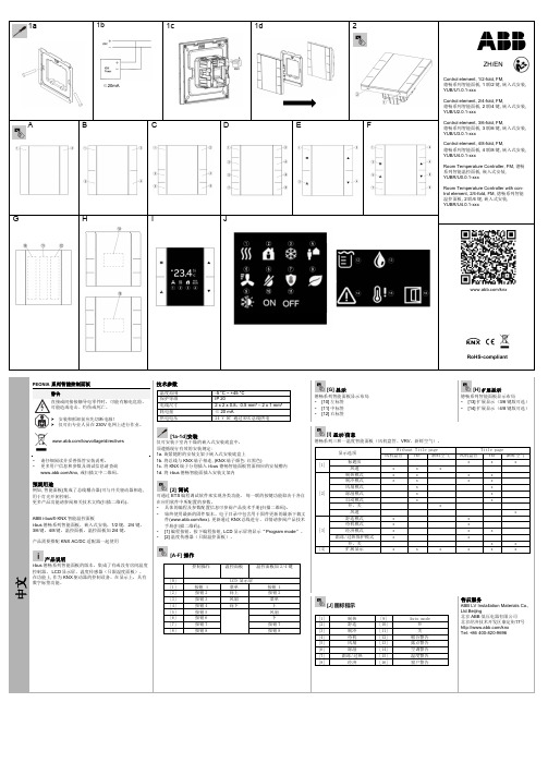
RoHS-compliant/knx1aA B C D E FG H I J中文PEONIA系列智能控制面板警告直接或间接接触导电零件时,可能有触电危险。
可能造成电击、灼伤或死亡。
安装和拆卸前应先切断电源!仅可由专业人员在230V电网上进行作业。
/lowvoltage/directives▪请仔细阅读并妥善保管安装说明。
▪更多用户信息和参数及调试信息请查询/knx,或扫描文中二维码。
预期用途例如,智能面板(集成了总线耦合器)可与开关驱动器相连,用于灯光开闭控制。
更多产品功能请参阅相关技术文档(扫描二维码)。
ABB i-bus® KNX智能温控面板i-bus德畅系列智能面板,嵌入式安装,1/2键,2/4键,3/6键,4/8键,温控面板,温控面板加2/4键。
产品需要搭配KNX AC/DC适配器一起使用产品说明i-bus德畅系列智能面板的版本,集成了有或没有房间温度控制器, LCD显示屏,温度传感器(只限温度面板)。
在功能上,作为KNX驱动器的控制设备。
在显示上,具有数字标签功能。
技术参数温度范围-5 °C ~ +45 °C保护等级IP 20电线尺寸 2 x 2 x 0.8,0.5 mm² – 2 x 1 mm²耗电量≤ 20 mA供电电压24 V DC 通过KNX总线供电[1a-1d]安装仅可安装于室内干燥的嵌入式安装底盒中。
须遵循现行有效的安装规定:1a.旋紧随附的安装支架于嵌入式安装底盒上1b.将总线与KNX端子相连, (KNX端子颜色:红黑色)1c.将KNX端子分别插入i-bus德畅智能面板背面相应的安装槽内1d.将i-bus德畅智能面插入安装支架内[2]调试可通过ETS编程调试软件来实现各类功能。
每一联的按键功能取决于各自在应用软件中所配置的参数。
▪具体的编程及参数配置信息可参阅产品技术手册(扫描二维码)。
▪始终使用最新的固件版本。
电子目录中包含用于固件更新的最新下载文件(/knx).更新通过KNX总线进行。
ABB机器人系统输入输出功能描述

ABB机器人系统输入输出功能描述输入功能:1.传感器输入:ABB机器人系统可以通过各种传感器实时获取外界环境信息。
例如,温度传感器可以用于监测环境温度,压力传感器可以用于测量液体或气体的压力。
这些传感器能够将环境信息转化为电信号,供机器人系统使用。
2.视觉输入:ABB机器人系统可以通过摄像头或激光扫描仪等设备获取视觉信息。
机器人系统可以使用这些信息来识别和跟踪目标物体,实现精准的位置和姿态控制。
3.指令输入:ABB机器人系统可以通过外部设备或控制台接收用户的指令。
用户可以通过编程或人机界面输入指令,控制机器人进行不同的工作任务。
输出功能:1.执行动作输出:ABB机器人系统可以根据输入的指令或程序执行特定的动作。
例如,机器人系统可以轻松地进行抓取、搬运、装配或焊接等操作,提高生产效率。
2.运动输出:ABB机器人系统可以通过驱动器和电机实现高精度的运动输出。
机器人系统能够根据输入的位置和速度指令,自动控制机械臂的关节运动,实现精确的定位和操作。
3.通信输出:ABB机器人系统可以通过网络或其他通信方式与外部设备进行通信。
机器人系统可以向外部设备发送各类信息,如状态报告、警报通知等,以及接收外部设备发来的信息,实现实时的数据交互。
4.数据输出:ABB机器人系统可以将处理后的数据输出到外部设备或数据库中。
这些数据可以用于后续的数据分析、决策支持和生产管理等。
1.高效性:ABB机器人系统能够快速响应输入,并实时输出相应的动作或数据。
这使得机器人系统能够高效地与外部环境和其他设备进行协调和通信,从而提高工作效率。
2.精确性:ABB机器人系统可以通过传感器和视觉技术等手段实时感知环境,实现精确的位置和动作控制。
这使机器人系统可以准确地完成各类工作任务,并保持高度一致性和重复性。
3.可扩展性:ABB机器人系统的输入输出功能可以根据具体需求进行扩展和定制。
无论是增加更多的传感器、视觉设备,还是与更多的外部设备进行通信,机器人系统都可以很方便地进行集成和升级。
温度传感器原理及热敏电阻NTC温度常数β值计算温度

温度传感器原理温度传感器热电偶是工业上最常用的温度检测元件之一。
其优点是:①测量精度高。
因温度传感器热电偶直接与被测对象接触,不受中间介质的影响。
②测量范围广。
常用的温度传感器热电偶从-50~+1600℃均可边续测量,某些特殊温度传感器热电偶最低可测到-269℃(如金铁镍铬),最高可达+2800℃(如钨-铼)。
③构造简单,使用方便。
温度传感器热电偶通常是由两种不同的金属丝组成,而且不受大小和开头的限制,外有保护套管,用起来非常方便。
1.温度传感器热电偶测温基本原理将两种不同材料的导体或半导体A和B焊接起来,构成一个闭合回路,如图2-1-1所示。
当导体A 和B的两个执着点1和2之间存在温差时,两者之间便产生电动势,因而在回路中形成一个大小的电流,这种现象称为热电效应。
温度传感器热电偶就是利用这一效应来工作的。
2.温度传感器热电偶的种类及结构形成(1)温度传感器热电偶的种类常用温度传感器热电偶可分为标准温度传感器热电偶和非标准温度传感器热电偶两大类。
所调用标准温度传感器热电偶是指国家标准规定了其热电势与温度的关系、允许误差、并有统一的标准分度表的温度传感器热电偶,它有与其配套的显示仪表可供选用。
非标准化温度传感器热电偶在使用范围或数量级上均不及标准化温度传感器热电偶,一般也没有统一的分度表,主要用于某些特殊场合的测量。
标准化温度传感器热电偶我国从1988年1月1日起,温度传感器热电偶和温度传感器热电阻全部按IEC国际标准生产,并指定S、B、E、K、R、J、T七种标准化温度传感器热电偶为我国统一设计型温度传感器热电偶。
(2)温度传感器热电偶的结构形式为了保证温度传感器热电偶可靠、稳定地工作,对它的结构要求如下:①组成温度传感器热电偶的两个热电极的焊接必须牢固;②两个热电极彼此之间应很好地绝缘,以防短路;③补偿导线与温度传感器热电偶自由端的连接要方便可靠;④保护套管应能保证热电极与有害介质充分隔离。
3.温度传感器热电偶冷端的温度补偿由于温度传感器热电偶的材料一般都比较贵重(特别是采用贵金属时),而测温点到仪表的距离都很远,为了节省热电偶材料,降低成本,通常采用补偿导线把温度传感器热电偶的冷端(自由端)延伸到温度比较稳定的控制室内,连接到仪表端子上。
iTEMP HART TMT122温度传感器用户操作手册说明书
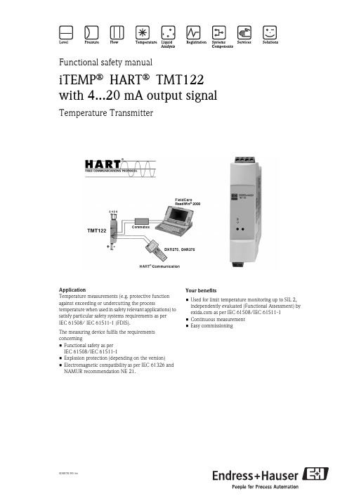
SD007R/09/enFunctional safety manualiTEMP ® HART ® TMT122with 4...20 mA output signalTemperature TransmitterApplicationTemperature measurements (e.g. protective function against exceeding or undercutting the processtemperature when used in safety relevant applications) to satisfy particular safety systems requirements as per IEC 61508/ IEC 61511-1 (FDIS).The measuring device fulfils the requirements concerning•Functional safety as per IEC 61508/IEC 61511-1•Explosion protection (depending on the version)•Electromagnetic compatibility as per IEC 61326 and NAMUR recommendation NE 21.Your benefits•Used for limit temperature monitoring up to SIL 2, independently evaluated (Functional Assessment) by as per IEC 61508/IEC 61511-1•Continuous measurement •Easy commissioningiTEMP® HART® TMT122 Table of contentsSIL Declaration of Conformity. . . . . . . . . . . . . . . . . . .3Introduction. . . . . . . . . . . . . . . . . . . . . . . . . . . . . . . . .4Abbreviations, standards and terms . . . . . . . . . . . . . . . . . . . . . . . . 4Determining the Safety Integrity Level (SIL) . . . . . . . . . . . . . . . . . 4Safety function with TMT122 . . . . . . . . . . . . . . . . . . .5Safety function for limit temperature monitoring . . . . . . . . . . . . . . 5Safety function data . . . . . . . . . . . . . . . . . . . . . . . . . . . . . . . . . . . 5Unit version . . . . . . . . . . . . . . . . . . . . . . . . . . . . . . . . . . . . . . . . . 6Supplementary device documentation TMT122 . . . . . . . . . . . . . . 6Commissioning and iterative tests. . . . . . . . . . . . . . . .6Using the unit forcontinuous measurements . . . . . . . . . . . . . . . . . . . . . . . . . . . . . . 6Suggestion for the procedure for the iterative tests. . .6Tools used for the iterative tests . . . . . . . . . . . . . . . . . . . . . . . . . . 6Test steps . . . . . . . . . . . . . . . . . . . . . . . . . . . . . . . . . . . . . . . . . . . 6Classification of error . . . . . . . . . . . . . . . . . . . . . . . . . . . . . . . . . . 7Analysis . . . . . . . . . . . . . . . . . . . . . . . . . . . . . . . . . . . . . . . . . . . . 7Settings . . . . . . . . . . . . . . . . . . . . . . . . . . . . . . . . . . . .7Settings . . . . . . . . . . . . . . . . . . . . . . . . . . . . . . . . . . . . . . . . . . . . 7Safety-related parameters . . . . . . . . . . . . . . . . . . . . . .8Specific safety-related parameters for TMT122 . . . . . . . . . . . . . . . 8PFDAVG dependent on selected maintenance interval . . . . . . . . . 8Repair . . . . . . . . . . . . . . . . . . . . . . . . . . . . . . . . . . . . .8Repair . . . . . . . . . . . . . . . . . . . . . . . . . . . . . . . . . . . . . . . . . . . . . 8 management summary. . . . . . . . . . . . . . . .9Appendix: Declaration of Hazardous Material and De-Contamination. . . . . . . . . . . . . . . . . . . . . . . . . . . . . .152Endress+HauseriTEMP® HART® TMT122Endress+Hauser 3SIL Declaration of ConformityFunctional safety of a temperature transmitter according to IEC 61508/IEC 61511Endress+Hauser Wetzer GmbH+Co. KG, Obere Wank 1, 87484 Nesselwangdeclares as manufacturer, that the temperature transmitteriTEMP ®HART ®TMT 122is suitable for the use in a safety-instrumented system according to standard IEC 61511-1, provided the relevant safety instructions are observed.The FMEDA provides the following parameters:SIL 2 Proof test interval 1 year Device type BHFT 1)0 (single channel use)SFF> 75 %PFD AVG 2) 4.82x10⁻⁴MTBF 3) 232 years Safety function 4)monitoring low level high level range λsd 26 FIT 124 FIT 141 FIT λsu 190 FIT 190 FIT 190 FIT λdd 132 FIT 33 FIT 17 FIT λdu110 FIT110 FIT110 FIT1) according to clause 11.4.4 of IEC 61511-12)the value complies with SIL2 according to ISA S84.01 and IEC 61511-1 3)according to Siemens SN29500 4)assuming setting of 4 to 20 mAThe device including the modification process was assessed on the basis of prior use.Nesselwang, 30 July 2003Endress+Hauser Wetzer GmbH+Co. KGGeneral managerSIL-03003a/09/eiTEMP® HART® TMT1224Endress+HauserIntroductionAbbreviations, standards and termsAbbreviationsExplanation to the abbreviations used can be found in the SIL-Brochure (SI002Z/11).Relevant standardsTermsDetermining the Safety Integrity Level (SIL)The achievable Safety Integrity Level is determined by the following safety-related parameters:•Average Probability of Failure on Demand (PFD AVG )•Hardware Fault Tolerance (HFT) and •Safe Failure Fraction (SFF).The specific safety-related parameters for the TMT122, as a part of a safety function, are listed in the "Safety-related parameters" chapter.The following table displays the dependence of the "Safety Integrity Level" (SIL) on the "Average Probability of Failure on Demand" (PFD AVG ). Here, the "Low demand mode" has been observed, i.e. the requirement rate for the safety-related system is maximum once a year.Sensor, logic unit and actuator together form a safety-related system, which performs a safety function. The "Average Probability of Failure on Demand" (PFD AVG ) is usually divided up into the sensor, logic unit and actuator sub-systems as per Figure 1.Fig. 1: Usual division of the "Average Probability of Failure on Demand" (PFD AVG ) into the sub-systemsStandard ExplanationIEC 61508,Part 1 – 7Functional safety of electrical/electronic/programmable electronic safety-related systems (Target group: Manufacturers and Suppliers of Devices)IEC 61511Part 1 – 3 (FDIS)Functional safety – Safety Instrumented Systems for the process industry sector (Target group: Safety Instrumented Systems Designers, Integrators and Users)Term ExplanationDangerous failureFailure with the potential to put the safety-related system in a dangerous or non-functional condition.Safety-related systemA safety-related system performs the safety functions that are required to achieve or maintain a safe condition e.g. in a plant. Example: temperature measuring device – logic unit (e.g. limit signal generator) – valve form a safety-related system.Safety functionDefined function, which is performed by a safety-related system with the aim of achieving or maintaining a safe condition for the plant, considering a specified dangerous incident. Example: limit temperature monitoringSafety Integrity Level (SIL)PFD AVG (Low demand mode)4≥ 10–5...< 10–43≥ 10–4...< 10–32≥ 10–3...< 10–21≥ 10–2...< 10–1iTEMP® HART® TMT122Endress+Hauser5!Note!This documentation considers the TMT122 as a component of a safety function.Safety Integrity Level TMT122 (Type B)The following table displays the achievable "Safety Integrity Level" (SIL) of the entire safety-related system for type B systems depending on the "Safe Failure Fraction" (SFF) and the "Hardware Fault Tolerance" (HFT).Type B systems are, for example, sensors with complex components such as ASICs (→ see also IEC 61508, Part 2).Safety function with TMT122Safety function for limit temperature monitoringFig. 2: Safety function (e.g. for limit temperature monitoring) with TMT122 as sub-systemThe TMT122 transmitter generates an analog signal (4...20 mA) proportional to the temperature. The analog signal is fed to a downstream logic unit, such as a PLC or limit signal generator, and there it is monitored to determine whether it exceeds a maximum value. In order to monitor for faults, the logic unit must be able to detect both HI-alarms ≥ 21.6 mA and LO-alarms ≤ 3.6 mA.Safety function data"Caution!The data for the safety functions are listed in the "Safety-related parameters" chapter.!Note!MTTR is set at eight hours.Safety-related systems without a self-locking function must be monitored or set to an otherwise safe state after carrying out the safety function within MTTR.Safe Failure Fraction (SFF)Hardware Fault Tolerance (HFT)01 (0)11)In accordance with IEC 61511-1 (FDIS), Clause 11.4.4, the "Hardware Fault Tolerance" (HFT) can be reduced byone (values in brackets), if the following conditions are true for devices using sensors and actuators with complex components:– The device is "proven in use".– The device allows adjustment of process-related parameters only, e.g. measuring range, upscale or downscale fai-lure direction, etc.– The adjustment level of the process-related parameters of the device is protected, e.g. by jumper, password (here: numeric code or key combination)– The function has a "Safety Integrity Level" (SIL) requirement less than 4.All conditions are true for the iTEMP ® HART ® TMT122.2 (1)1< 60%not permitted SIL 1SIL 260 ...< 90 %SIL 1SIL 2SIL 390 ...< 99 %SIL 2SIL 3–≥ 99 %SIL 3––iTEMP® HART® TMT1226Endress+HauserUnit versionSIL from unit version: 1.00.06Supplementary device documentation TMT122Depending on the version, the following documentation must be available for the temperature transmitter iTEMP ® HART ® TMT122:"Caution!•The installation and setting instructions, and the technical limit values must be observed in accordance with the Operating Instructions (KA128R and BA139R).•For devices which are used in explosion-hazardous, the supplementary documentation (XA) resp. Control Drawings must also be used in accordance with the table.iTEMP ® HART ® TMT122 supplementary documentation For further information, see Technical Information TI090R.Commissioning and iterative testsUsing the unit forcontinuous measurementsThe operability of the safety installation must be tested at appropriate time intervals. It is the responsibility of the user to select the type of check and the intervals in the specified time frame. The test must be completed in such a way that the fault free function of the safety installation combined with all components can be vaildated.Suggestion for the procedure for the iterative testsTools used for the iterative tests Ampere meter, wire bridgeTest steps1.With the connected sensor or a resistance simulator apply two points within the configured measurement range. Measure the output current with the ampere meter.2.Disconnect the sensor from the input. Measure the output current.3.Only if the transmitter is used with RTD: Make a shortcut at the sensor input (with the wire bridge) and measure the output current.Explosion protection/Certificates Operating instructions Other Ex-Documentation noneKA128R noneATEX II 2(1)G EEx ia IIC T4/T5/T6KA128R Safety instructions XA016R ATEX II 3G EEx nA IIC T4/T5/T6KA128RSafety instructions XA019RExplosion protection/Certificates Operating instructions ControlDrawings FM ControlDrawings CSA noneKA128R none none FM IS I/1+2/A-D CSA IS I/1+2/A-DKA128R KA128R14 14 01 11114 14 01 112iTEMP® HART® TMT122Endress+Hauser 7Classification of errorThe table below helps to classify the results of the test steps 1-3. If the result of one of the test steps is …dangerous“, the device has a dangerous error – the rest of the test steps may be skipped.Analysis If one of the test steps gives a result "dangerous", the device has a dangerous error.!Note!In this case please inform Endress+Hauser, that a device in a safety related application shows a dangerous error.SettingsSettingsIt is possible to do various settings on the TMT122. For further information see the BA139R operating instructions.Test stepTest resultOutput currentError classification1Error currentsafe1Output current is relative to applied signals (according to specification in TI)Normal function1Output current is not relative to applied signals dangerous 2Error currentsafe 2Any current different to error current dangerous 3 (only RTD)Error currentsafe 3 (only RTD)Any current different to error currentdangerousiTEMP® HART® TMT1228Endress+HauserSafety-related parametersSpecific safety-related parameters for TMT122The table displays the specific safety-related parameters for the TMT122.PFD AVG dependent onselected maintenance interval The following diagram presents the dependence of the PFD AVG on the maintenance interval. The PFD AVG increases as the maintenance interval increases.Fig. 4: "Average Probability of Failure on Demand" (PFD AVG ) dependent on the selected maintenance intervalRepairRepair!Note!Together with the failed, SIL-marked E+H device, having been operated in a functional safety application, the form "Declaration of Hazardous Material and De-Contamination" containing the appropriate information ":Used as SIL device in a Safety Instrumented System" has to be returned.The "Declaration of Hazardous Material and De-Contamination" can be found in the Appendix at the end of this Functional Safety Manual.TMT122SIL SIL 2HFT 0SFF > 75 %PFD AVG 4.82 x 10⁻⁴TI 11)Complete function testannualiTEMP® HART® TMT122Endress+Hauser 9 management summaryThe document was prepared using best effort. The authors make no warranty of any kind and shall not be liable inany event for incidental or consequential damages in connection with the application of the document.© All rights reserved.FMEDA and Proven-in-use AssessmentProject:Temperature head transmitter iTEMP® HART® TMT 182 andtemperature transmitters iTEMP® HART® DIN rail TMT 122 and TMT 112Customer:Endress+Hauser Wetzer GmbH + Co. KGNesselwang GermanyContract No.: E+H 02/11-05 Report No.: E+H 02/11-05 R005 Version V2, Revision R1.0, April 2005Stephan AschenbrenneriTEMP® HART® TMT12210Endress+Hauser © GmbH e+h 02-11-05 r005 v2 r1.0.doc, April 1, 2005Stephan Aschenbrenner Page 2 of 33 Management summaryThis report summarizes the results of the hardware assessment with proven-in-useconsideration according to IEC 61508 / IEC 61511 carried out on the temperature headtransmitter iTEMP® HART® TMT 182 with device version V1.02.08 and the temperaturetransmitters iTEMP® HART® DIN rail TMT 122 and TMT 112 with device version V1.00.06 andV1.00.04. Table 1 gives an overview of the different configurations which have been assessed.The hardware assessment consists of a Failure Modes, Effects and Diagnostics Analysis(FMEDA). A FMEDA is one of the steps taken to achieve functional safety assessment of adevice per IEC 61508. From the FMEDA, failure rates are determined and consequently theSafe Failure Fraction (SFF) is calculated for the device. For full assessment purposes allrequirements of IEC 61508 must be considered.Table 1: Configuration overviewConfigurations[CONF 1] Temperature head transmitter iTEMP® HART® TMT 182[CONF 2] Temperature transmitter iTEMP® HART® DIN rail TMT 122[CONF 3] Temperature transmitter iTEMP® HART® DIN rail TMT 112The failure rates used in this analysis are the basic failure rates of the Siemens standardSN 29500.According to table 2 of IEC 61508-1 the average PFD for systems operating in low demandmode has to be t10-3 to < 10-2 for SIL 2 safety functions. A generally accepted distribution ofPFD AVG values of a SIF over the sensor part, logic solver part, and final element part assumesthat 35% of the total SIF PFD AVG value is caused by the sensor part. For a SIL 2 application thetotal PFD AVG value of the SIF should be smaller than 1,00E-02, hence the maximum allowablePFD AVG value for the sensor part would then be 3,50E-03.The temperature head transmitter iTEMP® HART® TMT 182 and the temperature transmittersiTEMP® HART® DIN rail TMT 122 and TMT 112 are considered to be Type B1 components.Both have a hardware fault tolerance of 0.Type B components with a SFF of 60% to < 90% must have a hardware fault tolerance of 1according to table 3 of IEC 61508-2 for SIL 2 (sub-) systems.As the temperature head transmitter iTEMP® HART® TMT 182 and the temperaturetransmitters iTEMP® HART® DIN rail TMT 122 and TMT 112 are supposed to be proven-in-usedevices, an assessment of the hardware with additional proven-in-use demonstration for thedevice and its software was carried out. Therefore according to the requirements ofIEC 61511-1 First Edition 2003-01 section 11.4.4 and the assessment described in section 5.1 ahardware fault tolerance of 0 is sufficient for SIL 2 (sub-) systems being Type B componentsand having a SFF of 60% to < 90%.Assuming that a connected logic solver can detect both over-range (fail high) and under-range(fail low), high and low failures can be classified as safe detected failures or dangerous detectedfailures depending on whether the temperature transmitters are used in an application for “lowlevel monitoring”, “high level monitoring” or “range monitoring”. For these applications thefollowing tables show how the above stated requirements are fulfilled.Type B component: “Complex” component (using micro controllers or programmable logic); for detailssee 7.4.3.1.3 of IEC 61508-2.Endress+Hauser11© GmbH e+h 02-11-05 r005 v2 r1.0.doc, April 1, 2005Stephan AschenbrennerPage 3 of 33Table 2: Summary for TMT 182 – PFD AVG valuesT[Proof] = 1 year T[Proof] = 5 years T[Proof] = 10 years PFD AVG = 4,69E-04PFD AVG = 2,34E-03PFD AVG = 4,67E-03Table 3: Summary for TMT 182 – Failure ratesFailure CategoriesO sd O su O dd O du SFFDC S 2 DC D O low = O sd O high = O dd 26 FIT 165 FIT 108 FIT 107 FIT > 73% 14% 50% O low = O dd O high = O sd 101 FIT 165 FIT 33 FIT 107 FIT > 73% 38% 24% O low = O sd O high = O sd117 FIT165 FIT17 FIT107 FIT> 73%41% 14%Table 4: Summary for TMT 122 – PFD AVG valuesT[Proof] = 1 year T[Proof] = 5 years T[Proof] = 10 years PFD AVG = 4,82E-04PFD AVG = 2,41E-03PFD AVG = 4,80E-03Table 5: Summary for TMT 122 – Failure ratesFailure CategoriesO sd O su O dd O du SFF DC S ² DC DO low = O sd O high = O dd 26 FIT190 FIT 132 FIT 110 FIT> 75% 12% 55% O low = O dd O high = O sd 124 FIT 190 FIT 33 FIT 110 FIT > 75% 39% 23% O low = O sd O high = O sd141 FIT 190 FIT17 FIT110 FIT> 75%43% 13%Table 6: Summary for TMT 112 – PFD AVG valuesT[Proof] = 1 year T[Proof] = 5 years T[Proof] = 10 years PFD AVG = 4,85E-04PFD AVG = 2,45E-03PFD AVG = 4,83E-03Table 7: Summary for TMT 112 – Failure ratesFailure CategoriesO sd O su O dd O du SFF DC S ² DC DO low = O sd O high = O dd 25 FIT183 FIT 128 FIT 111 FIT> 75% 12% 55% O low = O dd O high = O sd 120 FIT 183 FIT 32 FIT 111 FIT > 75% 39% 23% O low = O sd O high = O sd136 FIT 183 FIT17 FIT111 FIT> 75%43% 13%2DC means the diagnostic coverage (safe or dangerous) of the safety logic solver for the temperature transmitters.12Endress+Hauser© GmbH e+h 02-11-05 r005 v2 r1.0.doc, April 1, 2005Stephan Aschenbrenner Page 4 of 33A user of the temperature head transmitter iTEMP® HART® TMT 182 and the temperature transmitters iTEMP® HART® DIN rail TMT 122 and TMT 112 can utilize these failure rates in a probabilistic model of a safety instrumented function (SIF) to determine suitability in part for safety instrumented system (SIS) usage in a particular safety integrity level (SIL). A full table of failure rates is presented in section 5.2 to 5.4 along with all assumptions.A complete temperature sensor assembly consisting of TMT 182, TMT 122 or TMT 112 and a closely coupled thermocouple or cushioned 4-wire RTD supplied with TMT 182, TMT 122 or TMT 112 can be modeled by considering a series subsystem where a failure occurs if there is a failure in either component. For such a system, failure rates are added.Section 5.5 gives typical failure rates and failure distributions for thermocouples and RTDs which were the basis for the following tables.Assuming that TMT 182, TMT 122 and TMT 112 are programmed to drive it’s output high on detected failures of the thermocouple or RTD (O low = O dd , O high = O sd ), the failure rate contribution or the PFD AVG value for the thermocouple or RTD in a low stress environment is as follows:Table 8: Summary for the sensor assembly TMT 182 / thermocouple in low stress environmentT[Proof] = 1 year T[Proof] = 5 years T[Proof] = 10 years SFF PFD AVG = 1,56E-03PFD AVG = 7,80E-03PFD AVG = 1,56E-02> 93%O sd = 4,85E-06 1/h = 4851 FIT O su = 1,65E-07 1/h = 165 FIT O dd = 3,34E-08 1/h = 33 FIT O du = 3,57E-07 1/h = 357 FITTable 9: Summary for the sensor assembly TMT 122 / thermocouple in low stress environmentT[Proof] = 1 year T[Proof] = 5 years T[Proof] = 10 years SFF PFD AVG = 1,58E-03PFD AVG = 7,90E-03PFD AVG = 1,58E-02> 93%O sd = 4,87E-06 1/h = 4874 FIT O su = 1,90E-07 1/h = 190 FIT O dd = 3,34E-08 1/h = 33 FIT O du = 3,60E-07 1/h = 360 FITTable 10: Summary for the sensor assembly TMT 112 / thermocouple in low stress environmentT[Proof] = 1 year T[Proof] = 5 years T[Proof] = 10 years SFF PFD AVG = 1,58E-03PFD AVG = 7,91E-03PFD AVG = 1,58E-02> 93%O sd = 4,87E-06 1/h = 4870 FIT O su = 1,83E-07 1/h = 183 FIT O dd = 3,24E-08 1/h = 32 FIT O du = 3,61E-07 1/h = 361 FITEndress+Hauser13© GmbH e+h 02-11-05 r005 v2 r1.0.doc, April 1, 2005Stephan Aschenbrenner Page 5 of 33Table 11: Summary for the sensor assembly TMT 182 / 4-wire RTD in low stress environmentT[Proof] = 1 year T[Proof] = 5 years T[Proof] = 10 years SFF PFD AVG = 5,56E-04PFD AVG = 2,78E-03PFD AVG = 5,56E-03> 94%O sd = 2,08E-06 1/h = 2081 FIT O su = 1,65E-07 1/h = 165 FIT O dd = 3,34E-08 1/h = 33 FIT O du = 1,27E-07 1/h = 127 FITTable 12: Summary for the sensor assembly TMT 122 / 4-wire RTD in low stress environmentT[Proof] = 1 year T[Proof] = 5 years T[Proof] = 10 years SFF PFD AVG = 5,69E-04PFD AVG = 2,85E-03PFD AVG = 5,69E-03> 94%O sd = 2,10E-06 1/h = 2104 FIT O su = 1,90E-07 1/h = 190 FIT O dd = 3,34E-08 1/h = 33 FIT O du = 1,30E-07 1/h = 130 FITTable 13: Summary for the sensor assembly TMT 112 / 4-wire RTD in low stress environmentT[Proof] = 1 year T[Proof] = 5 years T[Proof] = 10 years SFF PFD AVG = 5,74E-04PFD AVG = 2,87E-03PFD AVG = 5,74E-03> 94%O sd = 2,10E-06 1/h = 2100 FIT O su = 1,83E-07 1/h = 183 FIT O dd = 3,24E-08 1/h = 32 FIT O du = 1,31E-07 1/h = 131 FITTable 14: Summary for the sensor assembly TMT 182 / 2/3-wire RTD in low stress environment14Endress+HauserAppendixEndress+Hauser15International Head Quarter Endress+HauserGmbH+Co. KGInstruments International Colmarer Str. 679576 Weil am Rhein DeutschlandTel. +49 76 21 9 75 02Fax +49 76 21 9 75 34 5 ***************.comSD007R/09/en/12.05FM+SGML 6.0 ProMoDo。
abb机器人弧焊焊接与传感器应用手册
第一部分:abb机器人弧焊焊接应用1. 概述在制造业中,焊接是一个至关重要的工艺步骤。
而随着科技的不断进步,机器人焊接技术已经成为焊接行业的主流。
ABB机器人是一个备受信赖的品牌,其在弧焊焊接领域的应用手册更是备受瞩目。
2. ABB机器人在弧焊焊接中的应用在弧焊焊接领域,ABB机器人以其高速、高精度的特点成为众多厂商的首选。
其灵活的操作方式使得在不同形状和尺寸的工件上都能够进行精确的焊接。
ABB机器人搭配的焊接设备能够实现多种焊接方式和工艺参数的智能调整,从而为焊接工作提供了更加稳定和可靠的保障。
3. ABB机器人弧焊焊接应用手册在实际的生产过程中,很多厂家会提供相应的应用手册来指导用户如何正确地配置和操作ABB机器人进行弧焊焊接。
该手册会详细介绍机器人和焊接设备的参数设置、机器人程序的编写、安全注意事项等内容,以确保用户能够在实际操作中得到最佳的焊接效果。
4. 个人观点:弧焊焊接应用的未来机器人在弧焊焊接中的应用正在逐渐取代传统的人工焊接。
我认为,随着技术的不断革新和发展,机器人弧焊焊接将会在未来得到更大的应用,同时也将会不断地完善和提升其灵活性和智能化程度。
第二部分:传感器在ABB机器人弧焊焊接中的应用1. 传感器在焊接中的重要性在弧焊焊接中,传感器起到了至关重要的作用。
传感器能够实时地监测焊接过程中的温度、速度、气体流量等参数,从而及时调整焊接设备的工艺参数,保证焊接质量和稳定性。
2. ABB机器人弧焊焊接中的传感器应用ABB机器人在弧焊焊接中广泛利用各类传感器,如温度传感器、压力传感器、速度传感器等。
这些传感器能够实时监测焊接区域的情况,及时反馈到机器人系统,从而调整焊接参数,保证焊接质量。
3. 传感器在弧焊焊接中的应用手册很多带有传感器的焊接设备都会配备相应的应用手册,指导用户如何正确地配置和使用这些传感器。
用户可以根据手册中的指导,轻松地将传感器集成到焊接系统中,并根据实际需要进行参数设置和校准。
常见十大温度传感器品牌
1、日本(OMRON)欧姆龙OMRON欧姆龙集团始创于1933年,目前拥有近87年历史。
现有员工32583人,全球营业额6272亿日元,产品品种达几十万种,涉及工业自动化控制系统、电子元器件、汽车电子、社会系统以及健康医疗设备等广泛领域。
为了适应时代的发展,在公司成立50周年纪念时,公司名称与品牌名称实现了统一,改为“欧姆龙集团(株式会社)”。
创造社会需求,构筑“安心”,“安全”,“环保”“健康”的社会,是欧姆龙集团的发展目标。
2、德国(KROHNE)科隆德国KROHNE公司一直是国际测量领域的先驱,拥有先进技术和丰富的应用经验,使其能够根据市场的要求不断创新,从而提供给全球用户可靠、便捷、先进的测量仪器。
近百年来,KROHNE所研发的一系列新产品,不仅创造出多项世界第一,而且还成为测量领域里的标竿,引导着全球测量仪器的变革和发展。
3、美国(banner)邦纳BANNER始建于1966年,目前有54周年历史。
总部位于美国的明尼苏达州,是全球顶尖的自动化技术专家和整体解决方案提供者。
公司拥有22,000多种产品,具有最为齐全的产品线,经过40多年的发展,现已成为全球最大的光电传感器、测量检测、视觉传感器和机床安全产品的专业制造商之一。
丰富完整的产品选择、迅速的交货期、强大的技术支持以及同行业中首屈一指的研发能力保证了BANNER在同行业中的领军地位。
4、德国(IFM)易福门IFM是德国的一个工控品牌。
1969年德国易福门IFM这家家族企业发明了基于薄膜技术的电感式接近传感器,经过51年的发展从此走上了成功的道路。
今天,“efector”品牌成为了位置与流体传感器、物体识别、诊断和识别系统的代名词,而“ecomat”品牌则是网络和控制系统的杰出结果公司在全球70多个国家拥有5200多名员工,主要为机械制造等行业提供研发和销售服务,用户超过约10万家。
5、瑞士(ABB)ABB是电力和自动化技术领域的全球领导厂商,ABB集团位列全球500强企业。
abb热敏电阻电机保护继电器对应温度
abb热敏电阻电机保护继电器对应温度ABB热敏电阻电机保护继电器对应温度导言:ABB热敏电阻电机保护继电器是一种用于监测电机温度的装置。
它可以根据电机温度的变化来保护电机不受过热的损害。
本文将对ABB热敏电阻电机保护继电器的工作原理和对应温度进行全面评估,并探讨如何灵活应用该装置来实现电机的高效运行。
一、ABB热敏电阻电机保护继电器的工作原理ABB热敏电阻电机保护继电器通过监测电机温度来实现对电机的保护。
它基于电阻元件的温度特性,当电阻的温度升高到一定程度时,继电器会触发动作,切断电机的电源,以防止电机过热。
具体来说,ABB热敏电阻电机保护继电器包含一个热敏电阻元件和一个继电器开关。
热敏电阻元件通常被安装在电机的定子或转子上,直接感受电机的温度变化。
当电机运行时,温度会上升,电阻元件的阻值也会随之增加。
当阻值升高到设定的阈值时,继电器会被触发,切断电机的电源,从而避免电机过热。
二、ABB热敏电阻电机保护继电器的对应温度范围ABB热敏电阻电机保护继电器的对应温度范围是根据具体的应用要求进行设定的。
在不同的电机和工作环境中,对应的温度范围可能有所不同。
一般来说,ABB热敏电阻电机保护继电器的对应温度范围通常在50℃到180℃之间。
在设定ABB热敏电阻电机保护继电器的对应温度时,需要考虑电机的额定温度和运行温度范围。
额定温度是指电机在正常运行条件下的允许最高温度,而运行温度范围则是指电机在工作过程中的温度变化范围。
根据电机的额定温度和运行温度范围,可以设定ABB热敏电阻电机保护继电器的触发温度,以提供最佳的保护效果。
三、ABB热敏电阻电机保护继电器的应用与意义ABB热敏电阻电机保护继电器在电机保护中起着重要的作用,具有以下几个方面的应用和意义。
3.1 电机过热保护ABB热敏电阻电机保护继电器可以准确地监测电机温度,并在温度超过设定值时及时切断电源,以防止电机过热。
过高的温度会对电机的绝缘材料和内部结构造成损害,影响电机的寿命和运行效果。
常用温度传感器解析,温度传感器的原理、分类及应用
常用温度传感器解析,温度传感器的原理、分类及应用温度传感器(temperature transducer)是指能感受温度并转换成可用输出信号的传感器。
温度传感器是温度测量仪表的核心部分,品种繁多。
按测量方式可分为接触式和非接触式两大类,按照传感器材料及电子元件特性分为热电阻和热电偶两类。
温度传感器的分类接触式接触式温度传感器的检测部分与被测对象有良好的接触,又称温度计。
温度计通过传导或对流达到热平衡,从而使温度计的示值能直接表示被测对象的温度。
一般测量精度较高。
在一定的测温范围内,温度计也可测量物体内部的温度分布。
但对于运动体、小目标或热容量很小的对象则会产生较大的测量误差,常用的温度计有双金属温度计、玻璃液体温度计、压力式温度计、电阻温度计、热敏电阻和温差电偶等。
它们广泛应用于工业、农业、商业等部门。
在日常生活中人们也常常使用这些温度计。
随着低温技术在国防工程、空间技术、冶金、电子、食品、医药和石油化工等部门的广泛应用和超导技术的研究,测量120K以下温度的低温温度计得到了发展,如低温气体温度计、蒸汽压温度计、声学温度计、顺磁盐温度计、量子温度计、低温热电阻和低温温差电偶等。
低温温度计要求感温元件体积小、准确度高、复现性和稳定性好。
利用多孔高硅氧玻璃渗碳烧结而成的渗碳玻璃热电阻就是低温温度计的一种感温元件,可用于测量 1.6~300K范围内的温度。
非接触式它的敏感元件与被测对象互不接触,又称非接触式测温仪表。
这种仪表可用来测量运动物体、小目标和热容量小或温度变化迅速(瞬变)对象的表面温度,也可用于测量温度场的温度分布。
最常用的非接触式测温仪表基于黑体辐射的基本定律,称为辐射测温仪表。
辐射测温法包括亮度法(见光学高温计)、辐射法(见辐射高温计)和比色法(见比色温度计)。
各类辐射测温方法只能测出对应的光度温度、辐射温度或比色温度。
只有对黑体(吸收全部辐射并不反射光的物体)所测温度才是真实温度。
如欲测定物体的真实温度,则必须进行材料表面发射率的修正。
2024年温度传感器市场调查报告

2024年温度传感器市场调查报告1. 市场概述1.1 市场定义和范围温度传感器是一种用于测量和监控环境或物体的温度的装置。
它们通常用于工业控制、医疗设备、电子设备和汽车等领域。
1.2 市场动态随着工业和电子设备的发展,对温度传感器的需求不断增加。
同时,环境监测和能源管理等领域的发展也推动了温度传感器市场的增长。
2. 市场规模和趋势2.1 市场规模根据市场调查数据,温度传感器市场在过去几年保持了稳定增长的态势。
预计到2025年,市场规模将达到XX亿美元。
2.2 市场趋势2.2.1 技术进步随着技术的进步,温度传感器的精度和稳定性得到了显著提高。
新型传感器,如纳米材料和光纤传感器,已经在市场上得到广泛应用。
2.2.2 应用扩展温度传感器的应用领域日益扩展,除了传统的工业和电子设备领域,医疗、汽车和航空航天等领域也对温度传感器有着增加的需求。
3. 市场竞争状况3.1 主要厂商温度传感器市场存在着诸多主要厂商,包括ABB、Emerson、Honeywell和Siemens等。
这些公司在技术研发、市场拓展和服务等方面具有竞争优势。
3.2 市场份额根据市场研究,目前市场份额较大的公司是ABB和Siemens,它们分别占据了市场的XX%和XX%。
4. 市场前景展望4.1 市场驱动因素温度传感器市场的增长主要受到以下因素的驱动:•工业和电子设备的发展需求;•环境监测需求的增加;•节能和能源管理的需求。
4.2 市场挑战温度传感器市场面临的主要挑战包括:•技术进步的竞争压力;•价格竞争的增加;•法规和标准的变化。
4.3 市场机会温度传感器市场的机会包括:•新兴市场的发展需求;•应用领域的扩展需求;•不断增长的物联网市场。
5. 结论综上所述,温度传感器市场在过去几年保持稳定增长,并且未来有着良好的发展前景。
随着技术进步和应用领域的扩展,市场将继续增长。
同时,市场竞争激烈,厂商需提高技术研发和服务水平,以保持竞争优势。
ABB温度变送器TTH200
2
2
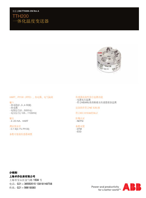
头部安装式温度变送器 TTH200 HART, Pt100 (RTD),热电偶,电绝缘 ,热电偶,电气隔离 HART,Pt100(RTD)
一体化温度变送器 TTH200
DS/TTH200Байду номын сангаасCN
DS/TTH200-CN
1 技术规格
1.1 输入 1.1.1 热电阻/电位计
RTD 电阻 Pt100 符合 IEC 60751、JIS C1604-81、MIL-T-24388 标 准,Ni 符合 DIN 43760,Cu 标准 电阻值 0 … 500 Ω 0 … 5000 Ω 传感器连接类型 二线、三线、四线制 连接电缆 每条线路的最大传感器线路电阻(RW)50 �,符合 NE 89 (2009 年 1 月)的规定 三线电路: 对称传感器线路电阻 二线电路: 最大可补偿 100 � 线路总电阻 电流测量值 < 300 μA 传感器短路 < 5 �(适用于 RTD) 传感器断路 测量范围:0 ... 500 Ω > 0.6 ...10 kΩ 测量范围:0 ... 5 kΩ > 5.3 ...10 kΩ 符合 NE 89 规定的腐蚀检测 三线电阻测量值> 50 Ω 四线电阻测量值> 50 Ω 传感器故障信号 RTD:短路及断路 线性电阻测量:断路
数据表 DS/TTH200-CN Rev.A
TTH200 一体化温度变送器
HART,Pt100(RTD),热电偶,电气隔离 输入 - 热电阻(2-,3-,4-线制) - 热电偶 - 电阻信号(0…5000Ω) - 电压信号(-125…1100mV) 输出 - 4~20 mA、HART 测量值误差 - 0.1 K(0.1% Pt100) 参数可根据传感器调整
ABB 传感器选型指南说明书

GeneralThe following questionnaires are used to select sensors according to the client's requirements.The characteristics shown in the catalogue are given with respect to a defined environment (worst case conditions).The technical requirements will not always reach these extreme limits, and it is possible, following confirmation by us, to propose higher maximum electrical or thermal values to those published, thanks to a knowledge and detailed analysis of the sensor operating environment.A technical relationship between the client and ABB will allow the proposal of the best selection of sensors, equally from the viewpoint of performance and economy.Two principal areas are considered in the selection of a sensor:–the electrical aspect–the thermal aspectThe sensor performance is based on a combination of electrical and thermal conditions; any values other than those indicated in this catalogue cannot be guaranteed unless validated by us. The information below is only valid for sensors using closed loop Hall effect technology.Contact your local supplier for other technologies.Profile missionDue to the design of converters with integrate more power with less volume, sensors are very constraint; leading to reduce their life time. As a matter of fact, even though the application main conditions are well within the sensors characteristics, these conditions have an impact on the sensor life time.The main general characteristics that involves the sensors life time are the following:–the ambient temperature above 40 °C. It is usually said that every additional 10 °C, the life time is reduced by a factor of 2. Of course, this value is a theoretical value and has to be defined in line with the concerned project.–the ambient temperature variations also impact the sensor life time. Even small variations (like 10 °C) can change the life time of the sensor especially on the electronic part.–the way the sensors are used also impact its duration (numbers of ON/OFF per day, average current or voltage value, powersupply value, load resistor value, vibrations levels…)The above general impacting conditions are well defined in standards like IEC 62380, UTE C 80-810 and must be consider during any new converter design.ABB can provide theoretical reliability calculation based on specific profile mission of your projects.Electrical characteristicsThe electrical characteristics values mentioned in this catalogue are given for a particular sensor operating point. These values may vary, according to the specific technical requirement, in the following way:–The primary thermal current (voltage) (I PN or U PN) may be increased if:-t he maximum operating temperature is lower than thevalue shown in the technical data sheet-the sensor supply voltage (V A) is reduced-the load resistance value (R M) is increased–The maximum current (voltage) measurable by the sensor may be increased if:-the maximum operating temperature is lower than thevalue shown in the technical data sheet-the sensor supply voltage (V A) is increased-the secondary winding resistance value (R S) is reduced(e.g. by using a lower transformation ratio)-the load resistance value (R M) is reducedThermal characteristicsThe operating temperature values mentioned in this catalogue are given for a particular sensor operating point. These values may vary, according to the specific technical requirement, in the following way:–The maximum operating temperature may be increased if: -the primary thermal current (voltage) (I PN or U PN) is reduced -the sensor supply voltage (V A) is reduced-the load resistance value (R M) is increasedPS: The minimum operating temperature cannot be lower than that shown in the technical data sheet as this is fixed by the lower temperature limit of the components used in the sensor.74S21Application1. Application :–Variable speed drive ................................................................ –UPS ....................................................................................... –Wind generator ....................................................................... –Active harmonic filter ............................................................... –Welding machines ................................................................... –Solar ...................................................................................... –Other (description) ......................................................................2. Quantity per year: ...........................................................................Mechanical characteristics1. Sensor fixing:–By soldering to the PCB .......................................................... –By the enclosure ..................................................................... –By the primary conductor ........................................................ 2. Primary conductor:–Cable diameter ................................................................... (mm) –Cable connection size ......................................................... (mm) –Bar size .............................................................................. (mm)3. Secondary connection:–By connector .......................................................................... –By cable without connector ..................................................... –Other ......................................................................................Sensor environmental conditions1. Minimum operating temperature ................................................ (°C)2. Maximum operating temperature ............................................... (°C)3. Presence of strong electromagnetic fields ....................................4. Max. continuous primary conductor voltage ................................ (V)5. Main reference standards ................................................................Electrical characteristics1. Nominal current (I PN ) ......................................................... (A r.m.s.)2. Current type (if possible, show current profile on graph):–Direct ..................................................................................... –Alternating .............................................................................. 3. Bandwidth to be measured ...................................................... (Hz)4. Current measuring range:–Minimum current .................................................................... (A) –Maximum current ................................................................... (A) –Duration (of max. current) .................................................... (sec) –Repetition (of max. current) ......................................................... –Measuring voltage (on R M ) at max current .............................. (V)5. Overload current (not measurable):–Not measurable overload current ........................................... (A) –Duration.............................................................................. (sec) –Repetition ...................................................................................6. Sensor supply voltage:–Bipolar supply voltage .......................................................... (±V) –Unipolar supply voltage .......................................... (0 +V or 0 -V)7. Output current–Secondary current at nominal current I PN ............................. (mA) 8. Current output (NCS range only)–Secondary current at maximum current I PMAX ....................... (mA)9. Voltage output–Secondary voltage at nominal current I PN ............................... (V)10. Voltage output (NCS range only)–Secondary voltage at maximum current I PMAX (V)Company:Address:Tel:Name:Fax:Email:Other requirements (description)74S 0201Company:Address:Tel:Name:Fax:Email:Other requirements (description)Application1. Project name ...................................................................................2. Application:Rolling stock:–Power converter ..................................................................... –Auxiliary converter ................................................................... –Other ......................................................................................Short or long distance train:–Power converter ..................................................................... –Auxiliary converter ...................................................................Metro or tramway:–Power converter ..................................................................... –Auxiliary converter ................................................................... Fixed installation (e.g. substation)..................................................... 3. Quantity per year: ............................................................................4. Total quantity for the project.............................................................Mechanical characteristics1. Sensor fixing:–By the enclosure ..................................................................... –By the primary conductor ........................................................ 2. Primary conductor:–Cable diameter ................................................................... (mm) –Bar size .............................................................................. (mm) 3. Secondary connection:–Screw or Faston...................................................................... –By connector .......................................................................... –By shielded cable .................................................................... –Other ...................................................................................... Electrical characteristics1. Nominal current (I PN ) .......................................................... (A r.m.s.)2. C urrent type (if possible, show current profile on graph):–Direct ..................................................................................... –Alternating .............................................................................. 3. Bandwidth to be measured ....................................................... (Hz)4. Current measuring range:–Minimum current .................................................................... (A) –Maximum current ................................................................... (A) –Duration (of max. current) .................................................... (sec) –Repetition (of max. current) ......................................................... –Measuring voltage (on R M ) at max current .............................. (V)5. Overload current (not measurable):–Not measurable overload current ............................................(A) –Duration.............................................................................. (sec) –Repetition ...................................................................................6. Sensor supply voltage:–Bipolar supply voltage .......................................................... (±V) –Unipolar supply voltage .......................................... (0 +V or 0 -V)7. Output current–Secondary current at nominal current I PN ............................. (mA) 8. Current output (NCS125 & NCS165 only for fixed installations)–Secondary current at maximum current I PMAX ....................... (mA)9. Voltage output (NCS125 & NCS165 only for fixed installations)–Secondary voltage at nominal current I PN ............................... (V)10. Voltage output (NCS125 & NCS165 only for fixed installations)–Secondary voltage at maximum current I PMAX (V)Sensor environmental conditions1. Minimum operating temperature ................................................ (°C)2. Maximum operating temperature ............................................... (°C)3. Average nominal operating temperature ......................................(°C)4. Maximum continuous primary conductor voltage ..........................(V)5. Main reference standards ................................................................74S 0201Company:Address:Tel:Name:Fax:Email:Other requirements (description)Application1. Project name ...................................................................................2. Application:Short or long distance train:–Power converter ..................................................................... –Auxiliary converter ...................................................................Metro or tramway:–Power converter ..................................................................... –Auxiliary converter ...................................................................Fixed installation (e.g. substation) ................................................ 3. Quantity per year: ............................................................................4. Total quantity for the project.............................................................Mechanical characteristics1. Primary connection:–By screw ................................................................................ –Other ...................................................................................... 2. Secondary connection:–Screw or Faston...................................................................... –By connector .......................................................................... –Other ...................................................................................... Electrical characteristics1. Nominal voltage (U PN ) ........................................................ (V r.m.s.)2. Voltage type (if possible, show voltage profile on graph):–Direct ..................................................................................... –Alternating .............................................................................. 3. Bandwidth to be measured ...................................................... (Hz)4. Voltage measuring range:–Minimum voltage .................................................................... (V) –Maximum voltage ................................................................... (V) –Duration (at max. voltage) .................................................... (sec) –Repetition (at max. voltage) ......................................................... –Measuring voltage (on R M ) at max voltage ............................... (V)5. Overload voltage (not measurable):–Not measurable overload voltage ............................................ (V) –Duration.............................................................................. (sec) –Repetition ................................................................................... –Category (from OV1 to OV3) ........................................................6. Sensor supply voltage:–Bipolar supply voltage .......................................................... (±V) –Unipolar supply voltage .......................................... (0 +V or 0 -V)7. Output current–Secondary current at nominal voltage U PN ............................ (mA)Sensor environmental conditions1. Minimum operating temperature ................................................ (°C)2. Maximum operating temperature ............................................... (°C)3. Average nominal operating temperature .....................................(°C)4. Main reference standards ................................................................74S 0201Company:Address:Tel:Name:Fax:Email:Other requirements (description)Application1. Project name ...................................................................................2. Application:Short or long distance train:–Power converter ..................................................................... –Auxiliary converter ...................................................................Metro or tramway:–Power converter ..................................................................... –Auxiliary converter ...................................................................Fixed equipment (e.g. substation) ................................................ 3. Quantity per year: ...........................................................................4. Total quantity for the project.............................................................Electrical characteristics1. Nominal voltage (U PN ) ............................................................ (V DC)2. Maximum voltage long duration: 5 min (U MAX2) ........................ (V DC)3. Maximum voltage overload: 20 ms (U MAX3) .............................. (V DC)4. Minimum voltage to be detected . (V)Sensor environmental conditions1. Minimum operating temperature ................................................ (°C)2. Maximum operating temperature ............................................... (°C)3. Average nominal operating temperature ..................................... (°C)4. Pollution degree ..............................................................................5. Over voltage category (from OV1 to OV3) .........................................6. Maximum ambient light level ......................................................(lux)7. Main reference standards ................................................................74S 0201。
ABB温度传感器说明书
警告 — 人体损伤 大于等于 DN 450 的设备检查螺钉(排放冷凝液)有可能处于受压状态。 液体喷出会造成严重伤害。 松开检查螺钉前必须对管路卸压。 检修工作必须由专业受训人员完成。 • 拆除设备前必须对设备、相邻管路和容器卸压。 • 打开设备前检查测量物料是否具有危险性。设备中可能仍残留部分危险物 料,打开设备时有可能泄漏造成危害。 • 以下各项内容属于操作人员责任,应定期予以检查: - 压力装置的压力壁/压力衬垫 - 测量功能 - 气密性 - 磨损(腐蚀)
警告 —<人体损伤> 此符号与“警告”信息表示存在潜在的危险。如不加以避免,可能造成严重 的伤亡事故。
小心 —<轻微损伤> 此符号与“小心”信息表示存在潜在的危险。如不加以避免,可能造成轻微 损伤事故。此符号也可用于财产损失警告。
注意 —<财产损失> 此符号表示可能造成财产损失!如不加以避免,设备或现场其他财产有可 能遭受损失。
重要信息 此符号表明操作提示或特别有用的信息,与危险或者财产损失无关。
Ol/TSP_ZA
SensyTemp TSP1X8
8
1.6
1.6.1
铭牌
铭牌(标准)
1 2 3 4 5 6
产品类型 变送器生产商 产品名称 序列感器参数 温度范围 温变器类型 保护等级 注意产品文档
1.9
运输安全提示
注意以下信息: • 设备运输过程中切勿受潮,按要求包装设备。 • 设备包装应考虑运输过程的颠簸振动,例如:采用气垫保护包装。 开箱后立即检查设备,是否有由于不当运输造成的损坏。将运输损坏记录在 运输单据上,在安装前立即向运输公司提出所有赔偿要求。
1.10
安装安全提示
注意以下信息: • 所有法兰连接必须符合最大扭矩要求。 • 传感器安装应避免不良机械张力(扭转、弯曲)。 • 使用共面对接法兰安装法兰型设备。 • 传感器安装应符合使用要求,配备合适的密封件。 • 拧紧法兰螺栓、螺母,消除管路振动带来的不良影响。
- 1、下载文档前请自行甄别文档内容的完整性,平台不提供额外的编辑、内容补充、找答案等附加服务。
- 2、"仅部分预览"的文档,不可在线预览部分如存在完整性等问题,可反馈申请退款(可完整预览的文档不适用该条件!)。
- 3、如文档侵犯您的权益,请联系客服反馈,我们会尽快为您处理(人工客服工作时间:9:00-18:30)。
Temperature sensors with exchangeable measuring insetI Components welded from pipe for low-stress applications;thermowells manufactured from barstock material forapplications with a high level of stress caused by pressure, fluid flow or aggressive mediaI For applications under pressure in vessels and pipelines withaggressive, explosive and gaseous mediaI Measuring element can be exchanged without any interruptionof the processI Ex i and Ex d explosion protectionMeasuring insetsI Standard design with extremely diverse electrical featuresI Used as an exchangeable measuring element in thermowells Sheathed thermocouples and resistance thermometersI Can be produced in greater lengths and subsequently bent I For applications that offer a low level of mechanical andaggressive stressStraight thermocouplesI For temperatures up to 1200 °C thermowells are used whichare made from heat-resistant steelsI For temperatures above 1200 °C ceramic thermowells areusedI Installed in hot gases, furnaces, incineration plantsSensyTemp Technical datafor temperature sensors10/10-3.03 ENPage 2 of 3007.00ContentsNew type listeNew name MeaningData Sheet Old name SensyTemp WT R W elded Protection T ube, R esistance Thermometer 10/10-3.22 EN TW 311/312SensyTemp TW R T hermo w ell, R esistance Thermometer 10/10-3.23 EN TW 321/322SensyTemp ET R E xtension T ube, R esistance Thermometer 10/10-3.24 EN TW 331/332SensyTemp WT T W elded Protection T ube, T hermocouple 10/10-3.25 EN TT 311/312SensyTemp TW T T hermo w ell, T hermocouple 10/10-3.26 EN TT 321/322SensyTemp ET T E xtension T ube, T hermocouple10/10-3.27 EN TT 331/332SensyTemp WT R-FP W elded Protection T ube, R esistance-F lame P roof 10/10-3.32 EN TW 411/412SensyTemp IS R I n s et, R esistance Thermometer10/10-3.41 EN WMF: TW 511/512SensyTemp IS R-iZ I n s et, R esistance-EEx i with PTB certificate of conformity 10/10-3.41 EN WMF-iZ: TW 511/512SensyTemp IS T I n s et, T hermocouple10/10-3.43 EN TMF: TT 511/512SensyTemp IS R-FP I n s et, R esistance Thermometer-F lame P roof 10/10-3.45 EN WMF-d: TW 511/512SensyTemp WT D W elded Protection T ube, D ial10/10-3.47 EN TB 311SensyTemp MI R-0M ineral I nsulated, R esistance Thermometer 10/10-3.56 EN FW 0SensyTemp MI R-1M ineral I nsulated, R esistance Thermometer 10/10-3.56 EN FW 1SensyTemp MI R-2M ineral I nsulated, R esistance Thermometer 10/10-3.56 EN FW 2SensyTemp MI R-31M ineral I nsulated, R esistance Thermometer 10/10-3.56 EN FW 31SensyTemp MI R-51M ineral I nsulated, R esistance Thermometer 10/10-3.56 EN FW 51SensyTemp MI T-0M ineral I nsulated, T hermocouple 10/10-3.57 EN FT 0SensyTemp MI T-1M ineral I nsulated, T hermocouple 10/10-3.57 EN FT 1SensyTemp MI T-2M ineral I nsulated, T hermocouple 10/10-3.57 EN FT 2SensyTemp MI T-31M ineral I nsulated, T hermocouple 10/10-3.57 EN FT 31SensyTemp MI T-51M ineral I nsulated, T hermocouple 10/10-3.57 EN FT 51SensyTemp ST B-AM S traight T hermocouple, B ase-metal, M etal Protection Tube10/10-3.58 EN TT 111, AM SensyTemp ST B-AMK S traight T hermocouple, B ase-metal,M etal Protection Tube, C eramic Inner Tube 10/10-3.58 EN TT 112, AMK SensyTemp ST P-AK S traight T hermocouple, P recious-metal, C eramic Protection Tube10/10-3.59 EN TT 113, AK SensyTemp ST P-AKK S traight T hermocouple, P recious-metal,C eramic Protection Tube, C eramic Inner Tube 10/10-3.59 EN TT 114, AKK SensyTemp BA R-R B uilding A utomation, R esistance Thermometer 10/10-3.61 EN WTR SensyTemp BA R-RF B uilding A utomation, R esistance Thermometer 10/10-3.61 EN WTRF SensyTemp BA R-A B uilding A utomation, R esistance Thermometer 10/10-3.61 EN WTA SensyTemp BA R-L B uilding A utomation, R esistance Thermometer 10/10-3.61 EN WTL SensyTemp BA R-Lm B uilding A utomation, R esistance Thermometer 10/10-3.61 EN WTLm SensyTemp BA R-Ro/1B uilding A utomation, R esistance Thermometer 10/10-3.61 EN WTRo/1SensyTemp BA R-Ro/2B uilding A utomation, R esistance Thermometer 10/10-3.61 EN WTRo/2SensyTemp HY R-1E Hy gienic, R esistance Thermometer 10/10-3.64 EN WTN 1E SensyTemp HY R-2E Hy gienic, R esistance Thermometer 10/10-3.64 EN WTN 2E SensyTemp HY R-5E Hy gienic, R esistance Thermometer 10/10-3.64 EN WTN 5E SensyTemp HY R-4EHy gienic, R esistance Thermometer10/10-3.65 ENWTN 4ETemperature sensors with welded thermowell and exchangeable measuring inset . . . . . . . . . . . . . . . . . . . . . . . . . . . . . . . . . . . . Page 3Temperature sensors with drilled thermowell and exchangeable measuring inset . . . . . . . . . . . . . . . . . . . . . . . . . . . . . . . . . . . . . Page 7Temperature sensors for installation in a thermowell, exchangeable measuring inset . . . . . . . . . . . . . . . . . . . . . . . . . . . . . . . . . . Page 11Ex d thermometers . . . . . . . . . . . . . . . . . . . . . . . . . . . . . . . . . . . . . . . . . . . . . . . . . . . . . . . . . . . . . . . . . . . . . . . . . . . . . . . . . . . . . Page 13Measuring insets for resistance thermometers and thermocouples . . . . . . . . . . . . . . . . . . . . . . . . . . . . . . . . . . . . . . . . . . . . . . . . Page 17Dial thermometers. . . . . . . . . . . . . . . . . . . . . . . . . . . . . . . . . . . . . . . . . . . . . . . . . . . . . . . . . . . . . . . . . . . . . . . . . . . . . . . . . . . . . . Page 22Sheathed temperature sensor. . . . . . . . . . . . . . . . . . . . . . . . . . . . . . . . . . . . . . . . . . . . . . . . . . . . . . . . . . . . . . . . . . . . . . . . . . . . . Page 25Straight thermocouples . . . . . . . . . . . . . . . . . . . . . . . . . . . . . . . . . . . . . . . . . . . . . . . . . . . . . . . . . . . . . . . . . . . . . . . . . . . . . . . . . . Page 27Designs SensyTemp WT R/WT TThe design– of thermocouples and resistance thermometers– for normal and Ex-i measuring circuitsis outwardly identical; the difference between them lies in the mea-suring inset ing measuring insets with a diameter of 6 mm or above, all the common combinations of sensors can be implemented in appropri-ate thermowells.Using a measuring inset with a diameter of 3 mm it is possible to achieve thinner thermowell tips (C2S, K2S and B2S) with a shorter response time.07.00Page 3 of 30ThermowellsAll thermowells for the temperature sensors are made of a drawn tube with a welded bottom plate. Depending on the mechanical and chemical stress imposed and the response time required, ther-mowell types can be selected with:– diverse external diameters / wall thicknesses– reduced measurement tip.Special designs and special materials or coatings can also be sup-plied.The directive 97/23/E G (Pressure E quipment Directive) are ful-filled. As the article 1, pragraph 2.1.4 does not apply, an Attest of Conformity and the CE-marking can not be done.Operating dataThe permissible stress depends on several factors:General application specifications cannot be given in view of man-ifold range of versions. The following table gives approximate val-ues. If conditions differ greatly a stress analysis acc. to Dittrich or Murdock is recommended.Response timesApart from protection tube mass at the measuring point, factors go-verning the heat transport are the chief determinants for the response time:– Medium, heat capacity– Pressure, density, moisture– Flow velocity.The following table features approximate values, refering to water or air. Greater flow velocities and heat capacities considerably re-duce the time intervals.The values T0.5 and T0.9 give information on the time period after which 50 % or 90 % of a sudden temperature change is displayed.Medium-related data Installation-related data– Medium– Viscosity– Flow velocity – Pressure– Temperature – Material– Protection tube type– Insertion length– Sealing pressure of theprocess connection– VibrationType∅ at tip In water 0.4 m/s In air 3 m/s(mm)T0.5T0.9T0.5T0.9Resistance thermometersB2S/K2S671852170K3S/B3/E19123088280C2111438106320ThermocouplesB2S/K2S671439128K3S/B3/E19102466210C211122880240Process connectionThe insertion length U is primarily dictated by the installation site. Since the process connection assembly can be affixed to any point of the thermowell, it is recommended that the extension tube length K should always be selected such that U+K produces the standard nominal length N.This results in shorter delivery times and a lower price and, to a large extent, relives the customer of the need to stock spare parts, since stock material can be used if needed.We supply:– as standard cylindrical threads with thread groove and seal collar acc. to DIN 3852 type A, as specified in the thermowell specification DIN 43772– welded flanges conforming to standards– adjustable compression fittings and flanges,which are adjusted once via a clamp ring when fitting (only for thermowells E… and K…)– process connections based on specific industrial and com-pany versions.As a standard procedure, the welded process connection is welded only at the extension end, since this enhances the flow end vibration withstand capabilities.Type DimensionsMaterial Process connection Max. flowvelocity (m/s)Max pressure (bar)for temperature (°C)Air Water f. insertionlength (mm)0100200300400B39 x 1 mm1.4571 (AISI 316-TI)Mounting thread G½“253160250400504018484018444018404018363618C2, C2S 11 x 2 mm1.4571 (AISI 316-TI)Mounting thread G1“405160250100509550925088508050K2 K2S E112 x 2,5 mm1.4571 (AISI 316-TI)Mounting thread G1“40516022028010010010010010010010010010010078551007855Page 4 of 3007.00Explosion protection type EEx iTemperature sensors– based on EN 50014 / EN 50020 pursuant to CENELEC are approved by PTB Certificate of Conformity no. Ex-94.C.4009, with a degree of protection EEx ia IIC T6 with a design appro-ved thermowell in zone 0 and with a connection head inzone1. This means that thermowells must conform to buil-ding regulations in respect of resistance to corrosion, mecha-nical stress, wall thickness and pressure tests. If the system supplied does not include a thermowell, then responsibility for using a suitable thermowell lies with the user. The tempe-rature sensors in this Data Sheet can not be placed in zone 0 unless a thermowell is fitted. Installed transmitters arecovered by a separate certificate of conformity.– with a measuring inset conforming to NAMUR NE 24 arecertified by a manufacturer’s declaration, outlining thecorresponding testing of the measuring inset.– differing from PTB-approved design can be certified for EEx i installation by means of a manufacturer’s declaration if they fulfil the requirements of EN 50020, Pkt. 5.4, to EN 60079-14 (VDE 0165 part 1). Sensors thus certified may only be instal-led in zones 1 and 2.For Ex i installation, the following electrical values apply to the tem-perature sensor:Max. measured voltage12 VCapacity of measuring inset280 pF/mInductance of measuring inset15 µH/mMax. surface temperature:For operation with transmitters the corresponding specifications should also be taken into account. Long thermowells must be sup-ported at intervals of 750 mm in the vessel if necessary to with-stand the fluid flow.Measuring insetsAll the measuring insets installed are made of a Mineral InsulatedCable (MIC) thus featuring a high degree of vibration resistance and flexibility. The standard measuring inserts installed are: Factors relating to measurement and design feasibility must be taken into consideration for resistance thermometers when select-ing the appropriate combination of measuring inset type, circuittype and tolerance.The lead resistance produces an additional measurement error in the 2-wire circuit due to the conductors of the measuring inset and of the connecting cables. The following values must be borne in mind for the measuring inset lead wires:– WMF- 3 mm Ø: 0.28 Ω /m (Cu lead wires) = 0.7 K(measuring error)– WMF- 6 mm Ø: 0.1 Ω /m (Cu lead wires) = 0.25 K(measuring error)– WMF- 6 mm Ø: 2.8 Ω /m (NiCr lead wires) = 7 K(measuring error)With class B (0.3 °C at 0 °C) the additional error caused by the line resistance should not exceed 0.3 °C, i.e. for WMF– 3 mm Ø max. 315 mm measuring inset length in a 2-wire circuit – 6 mm Ø max. 1025 mm meas. inset length in a 2-wire circuit. Temperature sensors with greater lengths than these, of type WMF-H and all those with restricted measuring resistance toler-ances, should only be connected in a 3-wire or 4-wire circuit.The diameter of the MIC limits the possibilities for the wire circuit. While 1 x Pt 100 can be implemented in all circuit types, with 2 x Pt 100 the following options are valid:– 3 mm Ø only in 2-wire circuit– 6 mm Ø bin a 4-wire circuit, only with NiCr lead wires anda special terminal block.Further technical details see page 17.Performance Measuring inset typeIS T-iZ Ø 6 mm IS T-iZØ 3 mmIS R-iZØ 6 mmIS R-iZØ 3 mm0 W0.5 W1.0 W 1.5 W 40 °C48 °C52 °C56 °C40 °C52 °C60 °C66 °C40 °C57 °C72 °C87 °C40 °C67 °C94 °C120 °CThermometer design Measuring inset typeStandard IS R / IS TEEx i with PTB certificate IS R-iZ / IS T-iZEEx i with manufacturer’s declaration IS R-i / IS T-iEEx i to NE 24IS R-iN / IS T-iNThese measuring insets along with technical information ontolerances can be found in Data Sheets 10 3.41 EN and10-3.43 EN.07.00Page 5 of 30Page 6 of 3007.00Connection headsThere are several connection heads available, differing with respect to material and lid-closure technique:1)With cable connectors authorised for use with degree of protection IP 67Connection head types Material Cable entry Degree of protection Lid closure Surface BUZ, BUS, BUZH, BUSH Aluminium PG 16IP 66 / 671)Hinged lid Painted BUKH Polyamide PG 13.5IP 66 / 671)Hinged lid Black B(H)Aluminium PG 16IP 66 / 671)With 2 screws Painted BBK, BBKHReinforced plasticPG 16IP 54Screwed lidBlackType BUZ aluminium Type BUS aluminiumType BUZH aluminiumType BUSH aluminiumfor installation of transmitter for installation of transmitterType BUKH polyamideType B aluminiumType BH aluminiumType BBK reinforced plasticfor installation of transmitterfor installation of transmitterType BBKH reinforced plastic for installation of transmitterDesigns SensyTemp TW R / TW TThe design– of thermocouples and resistance thermometers– for normal and Ex-i measuring circuitsis outwardly identical; the difference between them lies in the mea-suring inset ing measuring insets with a diameter of 6 mm or above, all the common combinations of sensors can be implemented in appropri-ate thermowells.Using a measuring inset with a diameter of 3 mm it is possible to achieve reduced thermowell tips with a shorter response time.07.00Page 7 of 30Thermowells Array All thermowells in this Data Sheet for the temperature sensors aredrilled from bar stock material and their outside shape machined.The following thermowell designs are obtainable, and they repre-sent models conforming to DIN as well as other company stan-dards. Thermowells of similar design can also be supplied to anyspecification.The directive 97/23/E G (Pressure E quipment Directive) are ful-filled. As the article 1, pragraph 2.1.4 does not apply, an Attest ofConformity and the CE-marking can not be done.Captions:L=Thermowell lengthC=Cone lengthU=Insertion lengthPage 8 of 3007.00Operational dataThe permissible stress depends on several factors:General application specifications cannot be given in view of manifold range of versions. Approximate values are given in the following diagrammes. If conditions differ greatly a stress analysis acc. to Dittrich or Murdock is recommended.Response timesApart from the thermowell mass at the measuring point, the factors governing the heat transport are the chief determinants for the re-sponse time:– Medium, heat capacity– Pressure, density, moisture– Flow velocity.The following table features approximate values, refering to water or air. Greater flow velocities and heat capacities considerably re-duce the time intervals.The values T0.5 and T0.9 give information on the time period after which 50 % or 90 % of a sudden temperature change is displayed.Medium-related data Installation-related data– Medium– Viscosity– Flow velocity – Pressure– Temperature – Material– Thermowell type– Insertion length– Sealing pressure of theprocess connection– VibrationType Conus In water 0.4 m/s In air 3 m/slength mm T0,5T0,9T0,5T0,9Resistance thermometers4 (D1/D4)6520633009004 (D2/D5)1251444235706Thermocouples4 (D1/D4)6516502357054 (D2/D5)1251040150500*)Type 4 (D2, D5)Thermowells c = 125 mm:Bend, stream length = 125 mmThermowell diameter = 24 mmThermowell inside diameter = 7 mm **)Type 4 (DS)Thermowells c = 65 mm:Bend, stream length = 65 mmThermowell diameter = 18 mmThermowell inside diameter = 3.5 mmFlow velocityWater = 5 m/sSteam = 60 m/sAir = 60 m/s07.00Page 9 of 30Extension tube jointAll thermowells are extended by means of an extension tube with a threaded connection on both sides. We recommend the selection of a tube whose extension length K is such that the thermowell length L + K produces the standard nominal length N. This results in shorter delivery times and a lower price and, to a large extent, relives the customer of the need to stock spare parts, since stock material can be used if needed.The extension tube and connection head are joined together by means of a coupling screw. This enables the head to be turned after assembly. For this reason it is usual to have welded mounting threads at the end of the extension tube.The measuring inset is spring loaded in such a way that it can be pressed down to the base of the thermowell. This should be taken into account for the measuring inset length (spring excursion = 0 to 8 mm).Other forms of fastening can also be provided for company-stan-dard designs of thermowell.We deliver as standard cylindrical threads with thread groove and seal collar acc. to DIN 3852 type A, as specified in the thermowell specification DIN 43772.Process connectionDrilled thermowells can be produced in versions for various differ-ent process connections:– For welding inFor this purpose a section of the thermowell with a fittingsystem is provided. With type 4 (D)-thermowells conforming to DIN 43 772 each cylindrical part is pushed into a welding socket and welded at its end.– For screwing inThe appropriate thread is already turned on the thermowell so that it can be screwed into a threaded connection.– For flange connectionweld-in and screw-in thermowells can be provided with a flan-ge, which is welded up. A thermowell that is screwed into a flange and then welded is capable of withstanding a greater level of stress.Explosion protection type EEx isee page 5Measuring insetssee page 5Connection headssee page 6Page 10 of 3007.00Designs SensyTemp ET R / ET TThe design– of thermocouples and resistance thermometers– for normal and Ex-i measuring circuitsis outwardly identical; the difference between them lies in the mea-suring inset ing measuring insets with a Ø of 6 mm or above, all the common combinations of sensors can be implemented in appropriate ther-mowells.Using a measuring inset with a Ø of 3 mm, it is possible to achieve reduced thermowell tips with a shorter response time.With the temperature sensors for installation in thermowells, the following thermometer types can be implemented:I Without extension tube– by combination with thermowell designs from tube, tempera-ture sensors as specified in Data Sheets10-3.22 EN and 10-3.25 EN– with screw fitting on to the measuring inset:fast responding temperature sensor for gases and liquids(head fixture may be required)Extension tube jointsee page 10Process connection I With extension tube– by combination with thermowells made from bar stockmaterial, temperature sensors as specified in Data Sheets10-3.23 EN and 10-3.26 EN– without additional thermowell, with welded measuring inset: fast responding temperature sensor for gases and liquids– Without additional thermowell, as a variant, withmeasuring insets as specified in Data Sheets 10-3.41 EN and 10-3.43EN. Explosion protection type EEx isee page 5Measuring insetssee page 5Connection headssee page 6DesignsThe designs are determined by the type of thermowell and of themeasuring inset (see table below):Thermowell Measuring inset Zone Type Construction Standard versions Diameter in mmWT R-FP/WT T-FP welded from tube C2X, K3X, E2X 6 (8; 9.5)0 TW R-FP/TW T-FP drilled from bar stock material P, PR, PK, PL, PT, PW, RD, D, DR 6 (8; 9.5)0ET R-FP/ET T-FP without thermowell with various different extension tubes 6 (8; 9.5)1, 2 WT R-FP/WT T-FP welded from tube C2SX, K3SX30 TW R-FP/TW T-FP drilled from bar stock material DT30ET R-FP/ET T-FP without thermowell with various different extension tubes31, 2Thermowells, extension tubes and process connectionE x-d thermometers are equipped with welded or drilled thermo-wells.– The process connection can be used with:– Welded thermowells (protection tubes)– Welded mounting thread– Welded flangeDrilled thermowells (thermowells):– Shaft for welding– Screw-on thread– Press-fit or screw-fit flange, welded.In order to increase stability, all these constructional types are equipped with reinforced extension tubes.The permissible operating load is dependent on many factors and, if required, can be determined by a Murdock or Dittrich calculation. Before the thermowell leaves the factory it is tested with static pressure test depending on the design of the thermowell and/or the process connection. If the operational pressure is not specified by the customer, then the values shown in the following table are adopted:We deliver as standard cylindrical threads with thread groove and seal collar acc. to DIN 3852 type A, as specified in the thermowell specification DIN 43772.Process connection Design pressureThread:½“Thread:¾“Flange:to DIN or ANSI40 bar80 barFlange nominal pressure Thread:¾“, 1“Flange:to DIN or ANSIWeld80 barFlange nominal pressureMaterial-dependent pressurefor thermowells conforming toDIN 43763Explosion protectionThe thermometers covered by this data sheet are certified by PTB approval no. EEx 86.B.1073X for degree of protection EEx d IIC T6 with– Thermowell in zone 0– Connection head in zone 1(with special check also in zone 0)Complete protection against explosion extending into the process medium can only be assured as long as the thermowell remains undamaged. It must meet the requirements for stability, corrosion resistance and max. dead volume.This should be clearly established under operational stress, and checked at intervals:– The resistance to chemical attack, pressure, fluid flow andvibration should be checked by calculation.– When installed in a vessel, supports should be providedwhere required due to the stresses.– The thermowell must be included in the recurrent pressuretests performed on the vessel.All the above measures combine to ensure that any explosion occurring in the terminal enclosure cannot spread either into the thermowell or surrounding area.Without a thermowell operation in zone 1 is permitted as long as it can be established that the protruding measuring inset cannot be damaged mechanically. This design can thus also be used for monitoring machine bearings and heat exchangers.Measuring inset and connection headThe measuring inset and connection head form one unit corre-sponding to PTB approval.For Ex d types, only the AGG Ex d and AGGH Ex d models of con-nection head should be used.– Material: grey cast iron– Screwed lid with IP 65 rubber seal, locking chain,– Locking screw, which can only be undone with a tool– Cable entry to the connection as stipulated by EN 50 018 – With thread for attaching a tube– With screw fitting for cable– Fitted bore hole for associated measuring insets– Grounding screw inside and outside– Weight approx. 2.5 kgA screw fitting for cable certified to EN 50018 (type Gothe, cable Ø12 mm) is incorporated, while other cable screw fittings or threads for tubes can be ordered as optional extras.Operating dataThe permissible sress depends on several factors:General application specifications cannot be given in view of manifold range of versions. The following table gives approximate values. If conditions differ greatly a stress analysis acc. to Dittrich or Murdock is recommended.Response timesApart from protection tube mass at the measuring point, factors go-verning the heat transport are the chief determinants for the response time:– Medium, heat capacity– Pressure, density, moisture– Flow velocity.The following table features approximate values, refering to water or air. Greater flow velocities and heat capacities considerably re-duce the response time.The values T0.5 and T0.9 provide information on the times after which 50 % and 90 % of a sudden temperature change are dis-played.Medium-related data Insertion-related data– Medium– Viscosity– Flow velocity – Pressure– Temperature – Material– Protection tube design– Insertion length– Sealing pressure of theprocess connection– VibrationType∅ at tip in water 0.4 m/s in air 3 m/s(mm)T0.5T0.9T0.5T0.9Resistance thermometersC2SX6101852170C2X111438106320Type Materialdimensions Process connection Max. flowvelocity (m/s)Max. pressure (bar)for temperature (°C)Air Water For insertionlength (mm)0100200300400C2X, C2SX 11 x 2 mm1.4571 (AISI 316-TI)welded mounting thread G¾“405160250100509550925088508050DesignsThe measuring insets shown here are designed for installation in fully-equipped temperature sensors.– Temperature sensors with welded thermowellData Sheets 10-3.22 EN and 10-3.25 EN– Temperature sensors with drilled thermowellData Sheets 10-3.23 EN and 10-3.26 EN– Temperature sensors for installation in a thermowellData Sheets10-3.24 EN and 10-3.27 EN– Temperature sensors in an Ex d explosion protectionData Sheet 10-3.32 EN In all the fully-equipped thermometers listed, the following measuring insets are installed as standard: IS T (thermocouple measuring insets), IS R (resistance thermometer measuring insets) and IS R-FP (E x d resistance thermometer measuring insets).Measuring inset lengthsSince a measuring inset can be used universally in many different designs of thermometer, measuring insets form the basis for the standardisation of thermometer lengths.Standard lengths of measuring inset are: 275, 375, 405, 435, 525, 555, 655, 735, 1025 mm. Custom lengths can also be produced. Additional equipement– Where the drill holes in the thermowell are of above average diameter, a sleeve can be pressed in the range of the resi-stance element to reduce the air gap. A tack-welded sleeve can be removed again so that a measuring inset can be used for drill holes > 6 mm and > 8 mm.– If a particularly good contact needs to be achieved for mea-surements on surfaces, the tip can be adjusted for the hole-bottom face.– With long, thin measuring insets a reinforcing tube can be fit-ted in order to prevent bending, kinking or vibration.– Measuring points without an additional thermowell should be sealed off to the connection head in order to safeguard the IP degree of protection.– Where there is heavy vibration, reinforced springs and screw-on caps can be fitted to the socket.IdentificationMeasuring insets are identified unambiguously on the type label on the underside of the base plate.– Type designation and additional designationThis defines the measuring inset type (along with, in somecases, details of the official approval no.) e.g.IS T IS R-iZ IS R-B IS R-iNEx-94.C.4009NE 24– Measurement element, tolerance, circuit typeDetails are provided here in abbreviated form of the internalconfiguration, e.g.1 x K Cl. 12 x Pt 100 1 x Pt 100 1 x Pt 100V B/2 1/2 B; 0/3 A/0-400/4 Explanation:For thermocouples:V Hot junction isolatedV Hot junction grounded·For resistance thermometersR L= Resistance of the lead wire in a 2-wire circuit,if > 0.1 ΩB/2 T olerance class B in 2-wire circuit1/2 B, 0/3 T olerance 1/2 Class B in 3-wire circuitA/0-400/4 T olerance Class A in the range 0-400 °C in4-wire circuit0.5; 280/4 Special tolerance 0.5 °C at 280 °C in4-wire circuit – Temperature range, serial no.This specifies the measuring range that is technically possible and an identification in relation to the order, e.g. .-40...1000 °C-200...450 °C-50...150 °C-200...450 °CSerial no. ... Serial no. ... Serial no. ... Serial no. ...EEx i measuring circuitsMax. internal inductance:L i = 15 mH/mMax. internal capacitance:Ci = 280 pF/mWhen used in thermowells, the surface temperature on the ther-mowell is correspondingly lower. When the measuring inset in a thermometer is changed, the end user takes on responsibility for its correct installation in a thermometer of the associated approval no. Customer must provide us with the serial number marked on the old component in order that we can check that the model or-dered is compatible with the component supplied originally and with the applicable certification.Ex d Explosion protectionsee page 16Vibration resistanceThe use of MIC and special resistance elements results in all mea-suring insets having a very high vibration resistance. The values (3g) currently defined in E N60751 (IE C60751) for increased requirements are exceeded by all types. TMF/WMF measuring in-sets can withstand continuous loads of 10 g (frequency range test-ed 10-500Hz). Short-term load can be much higher.。
