PowerPCB中PCB图转原理图
PowerPCB元件封装和库制作图文详解
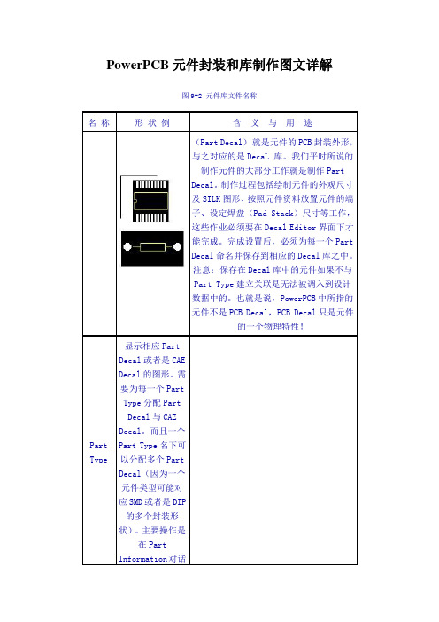
PowerPCB元件封装和库制作图文详解图9-2 元件库文件名称名称形状例含义与用途(Part Decal)就是元件的PCB封装外形,与之对应的是DecaL 库。
我们平时所说的制作元件的大部分工作就是制作PartDecal。
制作过程包括绘制元件的外观尺寸及SILK图形、按照元件资料放置元件的端子、设定焊盘(Pad Stack)尺寸等工作,这些作业必须要在Decal Editor界面下才能完成。
完成设置后,必须为每一个PartDecal命名并保存到相应的Decal库之中。
注意:保存在Decal库中的元件如果不与Part Type建立关联是无法被调入到设计数据中的。
也就是说,PowerPCB中所指的元件不是PCB Decal,PCB Decal只是元件的一个物理特性!Part Type显示相应Part Decal或者是CAE Decal的图形。
需要为每一个Part Type分配PartDecal与CAE Decal。
而且一个Part Type名下可以分配多个Part Decal(因为一个元件类型可能对应SMD或者是DIP 的多个封装形状)。
主要操作是在Part Information对话框下进行。
CAE Decal 我们还可以称之为Gate Decal,是元件的逻辑封装外形,如NOR、AND、OR电路等的外形符号,主要用于电路原理图中,代表元器件的一些外形符号,CAE Decal在PowerLogic中定义。
注意:通过其它CAD导入NETLIST或者是部分手工输入NETLIST的情况下,没有CAEDecal。
库名称用途Lib目录下的对应名称输出文件名称Decals 库0可以通过Import与Export命令将Decal元件导入和导出。
使用的文件后缀名称是.d 。
形式为:名称.dParts 库将上面的表1中的Part Type与Part Decal以及CAE Decal结合后就具有完整的Part信息,保存到该库中。
pads格式的PCB 导入到allegro之后再与orcad格式的原理图同步的全过程经验总结
源库替换掉原来有非法路径信息的库元件1 U: E" `: z( J0 G; m
元件的引脚也要严格区分,如某个引脚定义为output 则该引脚不能连到地。这也会造成同步失败
元件的引脚名和引脚号不能分别不能与另一个引脚有重复的部分)
转换后没有REF的问题,发现在不开ALLEGRO的情况下,直接运行PADS_IN.EXE是可以的,INI文件用安装目录下的。
E:\Cadence\SPB_15.5.1\tools\pcb\bin\pads_in.exe,E:\Cadence\SPB_15.5.1\tools\pcb\bin\pads_in.ini
2,pads输出powerpcb3.5格式的asc文件,
3,在allegro里面导入asc文件
4,在allegro导出库文件.
5,在用户设置里面,设置焊盘和flash的两个库文件的路径,都指向刚从allegro导出的库
6,打开orcad,输出网表,选择要同步的allegro PCB,并指定要生成的allegro PCB
导入pads格式的PCB 导入到allegro之后再与orcad格式的原理图同步的全过程经验总结)
步骤
1,先将orcad原理图与pads PCB严格同步,同时保证pads的每一种元件的库都有元件序号和值的label(两个label),不然会出现同步allegro传送网络表时会出现没有标示的问题
7,执行同步。(此过程会产生很多问题,大部分的问题原因是,
原理图的焊盘个数与PCB库焊盘个数不一致, 修改原理图,保证与PCB库一致
Power和PADS2007转GERBER操作
Powerpcb5.0和Pads Layerout2007 输出Gerber操作分享
LOGO
此菜单为定义原点位置
LOGO
将覆铜填充
LOGO
文件菜单下CAM为 POWERPCB输出 GERBER工具,点击 后出现如下图的窗口
LOGO
点击ADD菜单后可以 对所需要的导出的 GERBER或钻孔资料 内容和格式进设定
输出GERBER路 径和层名 文件名填 任何字符
LOGO
导出资料 的层选择
导出资料 的预览
导出 GERBER 资料的格 式设定
LOGO
点此处会出现 格式设定窗口 如下页
点此处会出现 D码编辑窗口LOGO右图中窗口为 GERBER格式 设定窗口
LOGO
输出线路 输出字符 输出阻焊 输出分孔图 输出钻孔
LOGO
LOGO
右图为钻孔格式
LOGO
在转分孔图时需注意孔位图和孔属性 和孔数表是不是重叠的,通过此窗口 可以更改设定将其 分开
LOGO
当我司把所需要的资料输出后,如何 验证我司输出的资料是否正确呢?可 以通过工具菜单将POWERPCB资料 直出输出CAM350 9.0版本的CAM资 料;此资料可以用于跟自己导出的资 料进行比对;
LOGO
输出线路层的窗口,此 窗口内可以对所导出的 线路层中内窗进行更改, 如将外框线去除;
LOGO
输出阻焊层的窗口,可以 将过孔阻焊开窗取消和客 户设计的大锡面转出;
LOGO
输出字符的窗口,注意 POWERPCB设计字符时 器件框和器件标识并不是 一个整体, PROTEL99SE设计的器 件封装都是一个整体,可 以直接导出完全的字符, 所以在导POWERPCB的 字符时一定要字符核对字 符是否可多的或者漏掉的;
PCB 格式转化方法

533 0
1
2
99
打开pads软件某一张图的pdb文件,然后选择export导出。
按如图所示选择对象及保存名字与格式
如下图所示
点击保存
跳出这样一个输出对话框点select all
格式的话选择powerpcbv3.5的扩展那里把两个选项也勾上最后再把cam去掉,这步骤和前面网上搜到的差不多。
假如你电脑上默认的是dxp的打开方式的话,它就会把asc文件变为上图。
在这里,由于我用的是altium designer9.0的版本,所以我就转成9.0格式的pcb图。
其他的protel99
可以参考此种方法,但不知有效否。
选择打开方式
打开后便会跳出如下的界面
一直点next即可
转换过程
最后完成时,变出现如左图所示的效果
原来的pads pcb图相比之下几乎没什么差别其他版本的99 dxp 都可以尝试下~~~估计也是会有效果
的。
下面是原理图的转换方法:
1
选择保存文件为TXT格式以便之后使用
选择导出
然后select all
选择2005版本的点击ok保存好。
打开altium designer9.0 然后打开刚才保存的
便出现如左图所示界面
然后一直next 便行。
这
便是最后转换出来的原理图完全一模一样
0人 | 分享到:
阅读(533)| 评论(0)| 引用 (0) |举报。
PowerPCB中PCB图转原理图
PowerPCB中PCB图转原理图教程来源:深圳龙人计算机发布者:D_K_BLUE 时间:2009-5-5 阅读:10774次PCB设计者在使用设计软件时都会用到软件的一种功能,就是PCB图转换成为原理图。
大多的PCB设计软件都会自带这种功能,比如说Protel系列软件98系列之后都能自己实现转换。
PowerPCB也有自动转换功能,但是实现过程相对复杂,下面我们就PowerPCB如何将PCB图转换成为原理图做简单介绍。
以PowerPCB提供的Pwrdemoa.pcb为例进行说明。
1.打开PCB图,选择菜单File-Report,文件类型选PowerPCB V3.0 Format Netlist ,将文件另存为Pwrdemoa.ASC。
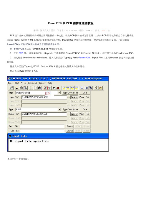
2.启动程序Omninet for Windows,输入文件类型(Type)选Pads-PowerPCB,Input File 1里用Browse指定网络表文件的位置。
输出文件类型(Type)选EDIF。
Output File 1指定输出文件的文件名和路径。
然后点击Run(跑动的小人)。
系统弹出一个输出窗口,点击Accept Data。
完成后点击“确定”,再点击“Done”关闭输出窗口。
退出Omninet for Windows。
3.修改EDIF网表文件,非常麻烦且容易出错的部分。
下面是网络表的一部分;(edif (rename C_COLON_BSLTEMP_BSLPWRDEMOA_DOTEDF "C:\TEMP\PWRDEMOA.EDF") (edifVersion 2 0 0)(edifLevel 0)(keywordMap (keywordLevel 0))(library MAIN_LIB(edifLevel 0)(technology(numberDefinition(scale 1 (e 1 -6)(unit distance))))(cell &6167 (cellType generic)(view NetlistView (viewType netlist)(interface)))(cell &6167 (cellType generic) (view NetlistView (viewType netlist) (interface(port &1 )(port &2 )(port &3 )(port &4 )(port &5 )(port &6 )(port &7 )(port &10 )(port &13 )(port &14 )(port &15 )(port &16 )(port &17 )(port &18 )(port &19 )(port &20 ))))(cell &68HC68R2 (cellType generic) (view NetlistView (viewType netlist) (interface(port &1 )(port &2 )(port &3 )(port &4 )(port &5 )(port &6 )(port &7 )(port &8 ))))(cell &68HC68R2 (cellType generic) (view NetlistView (viewType netlist)(interface)))(cell (rename NE555_MINUSSO "NE555-SO") (cellType generic)(view NetlistView (viewType netlist)(interface)))(cell (rename R1_FSL4W "R1/4W") (cellType generic)(view NetlistView (viewType netlist)(interface)))(cell (rename R1_FSL4W "R1/4W") (cellType generic)(view NetlistView (viewType netlist)(interface(port &1 )(port &2 ))))检查一下有(cell…..标记的行,特别要注意红色字体部分,其Interface部分为空,在这个cell标记的前面或后面又有一个cell 行,其Interface部分包含有(port &1)(port & 2)...等内容。
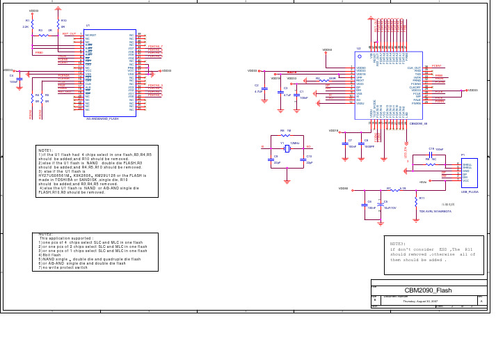
USB原理图和对应的PCB
善求至善1.PADS2000,如何阅读本书,这是一本技术用的图书,也是一本可以日后参考用的的工具书。
所以如果配合上机,一边阅读.一边依照本书章节的内容,一一将各个指令实际操作试用过一遍。
最后将这些功能与观念联系起来,相信制作一块自己的电路板时一定不成问题。
PADS Softwart Inc.公司位于美国麻萨诸塞洲万宝路市,是一个国际著名的电子设计自动化(EDA: Eiectrnic Design Automation)软件厂商。
公司先后推出过产品PADS-Login.PADS2000. PADS-Work. PADS-Perform .PADS-POWERLogin和PADS-PowerPCB等主流产品。
更是受到广大用户的一致好评,其无与伦比的强大功和易于使用的特点使得PADS始终保持PCB(印刷电路板)设计和分析工具的领导地位,从而取得了业界著名的PCB设计工具领导者的声誊......2.OrCAD\Cdpture 是用“使用者”的角度来写的,这就是本书的最大特色,毕竟这是一部工具书,它的任务是教导使用的人能够快速的学会操作OrCAD\Cdpture,并且在遇到问题的同时,便可以在本书中找到答案。
PADS-PowerPCB和OrCAD\Cdpture可以说是“夫妻关系”,这两大软件的配合做用,使得PCB(印刷电路板)设计中得心应手,至善至美......本人在深圳使用这二大软件从事电子工程师设计工作二十余年,主要是从事音响类产品设计,设计的产品主要销售国外欧美市场,国内也有部分产品销售。
本人手上有B.移动硬盘等相对应的原理图和PCB文档,主要是有:PowerPCB-5.0. OrCAD\Cdpture-9.1这二大软件的安装程序和详细的使用工具书。
若有需求者可以提供一套完整的PCB设计资料来共同学习。
有意者请加QQ:706958588 不诚者勿扰!注明:电子电路网信息。
谢谢!我的选择.你的决策.将是双赢的起点。
PowerPcb文件与Protel文件之间的转换方法
PowerPcb文件与Protel文件之间的转换方法PowerPcb文件与Protel文件之间的转换方法PowerPCB PCB文件转换成Protel文件的方法第一种方法:首先在PowerPCB中用Export命令导出ASCII文件(最好选低一点版本格式如3.6或4.0),然后确定已在Protel 99SE中安装了SP6补丁(如没安装可到Protel公司网站下载安装,网址是/downloads/files/protel99seservicepack6.exe),然后再安装一个叫PADS Importer的工具插件(下载网址是/downloads/files/padsimporter.exe),接着在Protel99SE中创建一个新的PCB文件,用Import命令导入刚才保存的.ASC的文件(文件类型选择PADS *.ASC格式),然后选择一下PowerPCB中的板层对应到Protel中对应的板层等等,这样就把PowerPCB文件完完全全的转到了Protel中了。
第二种方法:同样是在PowerPCB中导出ASCII文件,然后在Orcad中导入PowerPCB的ASCII文件,然后存为Orcad Layout的PCB格式.max,最后Protel中直接导入Orcad的Layout文件.max 即可完成转换工作。
(此法是采用Orcad与PowerPCB及Protel都具有良好的兼容性为基础的,但因Orcad在国内不太普及的缘故,以及要经两次转换是否会造成PCB板图其它问题,故此方不推荐使用!)第三种方法:采用CAM350 v6.0的Import来引入PowerPCB文件,具体方法为CAM350 v6.0:File->Import->CAD Date->PADS/PowerPCB 。
第四种方法:如果只想把文件转到Protel中去,比如你是要它的结构图之类的数据,你可在PowerPCB 中的输出中选择保存为DXF文件,再用CAM350、AutoCAD2000、Protel导入打开也可。
PowerPCB与Protel互转方法

1. protel99se 的原理图(sch)和PCB和ascii 网表文件(.prt &.net format)转到powerpcb/PAD的方法;方法1:在protel99se中的原理图或者pcb生成ascii 网表文件(可以由.prt &.net format两个文件合成.asc格式的); 注意:在protel PCB中导出的直接就是asc 格式,但是选择的类型为PAD ASCII;然后在powerpcb中import文件即可;方法2:安装PAD9.2或其他版本,软件带有转换的translator程序,可以在“开始”--> "程序"中找到;选择原理图或PCB的转换,挺方便的。
如果此时又要转到powerpcb,也是很方便的。
因为PAD9.2是高版本的,可以导出POWERPCB5.0等低版本兼容的ASCII网表文件,然后用低版本的直接就可以导入打开。
注:PAD9.2的translator功能很强大,可以将很多其他画图工具转换过去打开,如orcad原理图等。
???有些疑问:在转换的过程中,有些警告和错误怎么纠正?2. powerpcb转protel99se 的原理图(sch)和PCB和ascii 网表文件(.prt &.net format)方法;看到还是有很多人不明白怎么样转powerpcb成protel,我呢也是在论坛上问出来的,可能大家回复的时候有些细节没有注意到,我在这里总结一下,希望对那些不会转powerpcb成protel的人有用。
第一步:用PowerPCB打开文件,选择Export导出,导出格式Format选择PowerPCB V3.5的,然后Select All,但是倒数第五个的Rules不要选择,Parts和Nets 可以都选上。
然后导出.ASC文件。
第二步:打开Protel99se+sp6(我用的sp6,我不知道没有sp6能不能导入,好像是不行的),这里要注意,不是在Protel的的Document里面直接Import,这样就出现了很多人说导入进来了打开却说文件类型不对,然后一片白,什么都没有,那是因为这种操作是错误的。
PowerPCB的使用经验-电子进修网-PoweredbyStudydz.co...
PowerPCB的使用经验-电子进修网-PoweredbyStudydz.co...PowerPCB的使用经验PowerPCB 目前已在我所推广使用,它的基本使用技术已有培训教材进行了详细的讲解,而对于我所广大电子应用工程师来说,其问题在于已经熟练掌握了PROTEL之类的布线工具之后,如何转到PowerPCB的应用上来。
所以,本文就此类应用和培训教材上没有讲到,而我们应用较多的一些经验技巧作了论述。
1.输入的规范问题对于大多数使用过PROTEL的人来说,刚开始使用PowerPCB的时候,可能会觉得PowerPCB的限制太多。
因为PowerPCB对原理图输入和原理图到PCB的规则传输上是以保证其正确性为前提的。
所以,它的原理图中没有能够将一根电气连线断开的功能,也不能随意将一根电气连线在某个位置停止,它要保证每一根电气连线都要有起始管脚和终止管脚,或是接在软件提供的连接器上,以供不同页面间的信息传输。
这是它防止错误发生的一种手段,其实,也是我们应该遵守的一种规范化的原理图输入方式。
在PowerPCB设计中,凡是与原理图网表不一致的改动都要到ECO方式下进行,但它给用户提供了OLE链接,可以将原理图中的修改传到PCB中,也可以将PCB中的修改传回原理图。
这样,既防止了由于疏忽引起的错误,又给真正需要进行修改提供了方便。
但是,要注意的是,进入ECO方式时要选择“写ECO文件”选项,而只有退出ECO方式,才会进行写ECO文件操作。
2.电源层和地层的选择PowerPCB中对电源层和地层的设置有两种选择,CAM Plane和Split/Mixed。
Split/Mixed主要用于多个电源或地共用一个层的情况,但只有一个电源和地时也可以用。
它的主要优点是输出时的图和光绘的一致,便于检查。
而CAM Plane用于单个的电源或地,这种方式是负片输出,要注意输出时需加上第25层。
第25层包含了地电信息,主要指电层的焊盘要比正常的焊盘大20mil 左右的安全距离,保证金属化过孔之后,不会有信号与地电相连。
PowerPCB教程
PowerPCB教程作为一款强大的PCB设计软件,PowerPCB可以帮助工程师们完成各种复杂的PCB设计任务。
在本篇文档中,我们将为初学者介绍PowerPCB的基本功能和常用操作,帮助他们快速上手,并顺利完成自己的设计任务。
一、PowerPCB的基本功能:1.原理图设计:PowerPCB可以快速绘制电路原理图,并将其与PCB板联系起来。
用户可以方便地设置元器件的位置、电气属性、管脚等。
2. PCB布局:PowerPCB利用工具和功能强大的自动布局和线路连接技术,可以方便绘制复杂的PCB电路板。
3. 3D设计:PowerPCB可以方便地进行3D设计,使你能更好地收集电子元件及设计PCB 硬件。
二、PowerPCB常用操作:1.创建新项目:首先在软件的导航栏选择“新建文件”,选择项目类型(如单板、双面板,多层板等),选择板尺寸,元件之间的距离与层数。
2.绘制器件:在新创建的项目中使用“拖动”和“放置”操作来添加各种元器件。
一般情况下,可以在库中搜索需要的器件并添加到设计图中。
3.设置参数:可以通过在侧边栏和上方工具栏选择电气原理图元件并分配属性,设定电流/电压等需要的属性。
在元件安放好后,可以通过对元件安排的微调来达到最佳电路的效果。
4.建立线路:在完成器件库和相关属性设置后,还需要建立电路连接。
在PowerPCB 中,选中起始装配点和终止装配点,并用电线工具连接它们。
5.布局布线:在进行布线之前,可以通过“优化布局”选择让元器件摆放得尽可能紧密,或者在元件之间留出一些空余区域。
在布局完成后,开始进行布线,你可以选择逐步布线并且根据需要进行排版。
三、怎样提高PowerPCB的使用效率?1.组合命令:基本命令可以进行组合,以减少键盘输入或手动鼠标操作,通过“工具-按键映射-组合命令”即可完成。
2.使用规则检查:规则检查功能可以帮助检测电气签名、长度匹配、阻抗等电路布局问题,可以用来发现设计中存在的潜在问题。
PCB电路板PPCB元件封装和库制作图文详解(20210120161215)
PowerPCB 元件封装制作图文详解!新手一定要看!PowerPCB 元件封装制作图文详解!***************************************************我们习惯上将设计工作分为三大阶段,指的是前期准备阶段、中间的设计阶段以及后期设计检查与数据输出阶段。
前期准备阶段的最重要的任务之一就是制作元件,制作元件需要比较专业的知识,我们会在下一部教程中专门介绍。
但是学会了做元件只是第一步,因为元件做好后还必须保存起来,保存的场所就是我们现在要讨论的元件库,而且在PowerPCB 中只有将元件存放到元件库中之后,才能调出使用。
因此做元件与建元件库操作是密不可分的,有时还习惯将两个操作合而为一,统称为建库。
建库过程中的重要工作之一就是对元件库的管理,可以想像一个功能强大的元件库,至少要能满足设计者的下列几方面的要求:必须能够随意新建元件库、具有较强的检索功能、可以对库中的内容进行各种编辑操作、可以将元件库中的内容导入或者是导出等等。
下面我们将分几小节对PowerPCB 元件库的各种管理功能进行详细讨论。
一,PowerPCB 元件库基本结构1.元件库结构在深入讨论之前,有必要先熟悉PowerPCB 的元件库结构,在下述图9-1 已经打开的元件库管理窗口下,我们可以清晰地看到四个图标,它们分别代表PowerPCB 的四个库,这是PowerPCB 元件库的的一个重要特点。
换句话说,每当新建一个元件库时,其实都有四个子库与之对应。
有关各个库的含义请仔细阅读图9-1 说明部分。
图9-1 各元件库功能说明例如我们新建了一个名为FTL 的库后,在Padspwr 的Lib 目录下就会同时出现四个名称相同但后缀名各异的元件库,如图9-2 分别为:FTL.pt4 :PartType 元件类型库FTL.pd4 :PartDecal 元件封装库FTL.ld4 :CAE 逻辑封装库FTL.ln4 :Line 线库这是Padspwr 的Lib 目录下的所有元件库的列表,在这里可以找到所有元件库,包括系统自带的与客户新建的库。
如何从PCB转原理图
如何从PCB转原理图关于PCB转原理图(一点建议)1、分析PCB布局,把电路分成若干单元;2、准备两台电脑,一台查看PCB文档,一台绘制原理图;3、调取单元电路内的所有元件,跟据经验进行布局;4、将PCB文档内一条网络高亮度显示,在另一台电脑上连接电性联接线;整条网络接完后,删降PCB文档内的该条网络;5、重复上面两项,直到PCB文档内所有网络被删完,再对原理图进行优化。
按实物画电原理图的方法与技巧在维修电子产品遇到疑难故障又找不到图纸时,或对无图纸的电子产品进行剖析、改进时,都需要根据实物画出电路原理图。
这也是广大电子爱好者必须掌握的技巧之一,现笔者就此问题谈谈有关方法与技巧。
1.选择体积大、引脚多、在电路中起主要作用的器件如变压器、三极管、集成电路等作画图的参照物,然后从选择的参照物的引脚开始画图,这样可大大减少出错机会。
2.当印刷电路板上标有元件序号时,如VQ870、R330、C466等,注意这些序号的编排是有规律的,即英文字母后的第一个阿拉伯数字相同的元件属于同一功能分区。
早期的电路板上的元件序号为英文字母前的阿拉伯数字代表功能分区,如3BG12、2L15、7R21等。
正确区分同一功能分区的元器件,是画图布局的基础。
3.如果印刷电路板上没有标出元器件的序号,为便于分析与校对电路,要给元器件编号。
在设计印刷电路板进行元器件布局时,为使铜箔走线最短,一般把同一功能分区的元器件相对集中地布置在一起。
确定了起主要作用的参照器件后,只要顺藤摸瓜就能找到属于同一功能分区的其他元件。
4.正确区分印刷电路板上的地线、电源线和信号线。
如电源变压器次级所接的整流二极管的负端为电源正极,它与地线两端一般接有大容量的滤波电容器,且电容器外壳上有极性标志。
也可根据三端稳压集成电路引脚找出电源线和地线。
通常在设计印刷电路板进行布线时,为防止电路自激、抗干扰等,一般把地线铜箔设置得最宽(高频电路中往往有大面积接地铜箔),电源线铜箔次之,信号线铜箔最窄。
POWER PCB文件转换gerber步骤
用同样的方法转换所 有的图形(负片)
8. 字符转换设置
在第6项中给定一个 Document Name,选中 Silkscreen,弹出一个 介面选择TOP层→点击 左下角的Layers,弹出 下图,首先用鼠标点击 Selected框中的TOP, 请仔细观察图中的选项; 选项完毕按Preview进 行内容预览,查看其效 果
Name,选中Nc Drill ,选择Options
弹出下图,请仔细观察图中的选项
注: 注1 .Through Via表示过 孔, Plated Pi 表示金属化孔, Non-Plated Pi为非金属化孔, 三项都需选中
2. Partial V表示为埋盲孔, 如果Partial V被激活表示该板 存在埋盲孔。
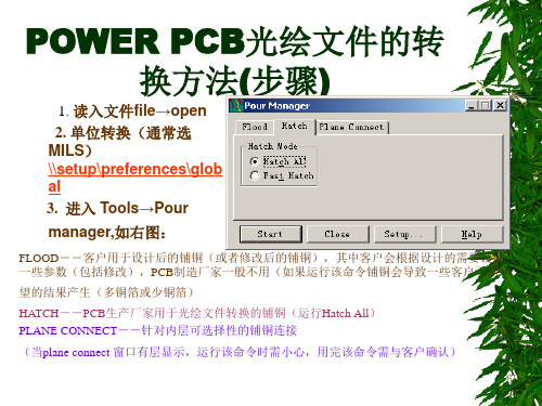
望的结果产生(多铜箔或少铜箔)
HATCH--PCB生产厂家用于光绘文件转换的铺铜(运行Hatch All) PLANE CONNECT--针对内层可选择性的铺铜连接
(当plane connect 窗口有层显示,运行该命令时需小心,用完该命令需与客户确认)
4. 观看图形显示效果 5. 进入Setup→Layer
Document Name,选中 Solder Mask,弹出一个介 面选择TOP层→点击左 下角的Layers,弹出下 图,首先用鼠标点击 Selected框中的TOP,仔 细观察各选项;选项完 毕按Preview进行内容预 览,查看其效果
注:Vias选项为过孔是否盖绿油, 选中为过孔不盖绿油,不选为盖 绿油
文件转换过程中常见的问题、错误信息提示及 其解决方法:
1. 版本的如何识别?
由于POWER PCB软件的版本众多其所设计 的文件目前无法通过文件来判别,只能询问 设计人员
POWERPCB 转 Gerber 详解
Outlines;零件外框线
用鼠标选择所需项目,选中项目转为白色。
(6)参数设定◎
项目选择完毕后,选择Next Menu项进入参数设定层菜单,其中各项参数如下:
a. Plot Scaling Ratio:1 to 1
此项为输出比例设定,1 to 1为原大,1 to 2o缩小二倍,2 to 1为放大二倍。
注:电气特性层之外的其它层,称为引申层。
PADS所产生的每个GERBER文件,都可以由JOB文件中的几个层迭加而成。而每一种输出类型所允许的迭加层数不同,其限制如下:
Gerber Plot : 0~4个任意层;
Artwork Plot : 1个电气特性层和0~3个引申层;
Silkscreen:0~3个引申层;◎
Board:板框 Pads:焊盘
Connections:鼠线 Vias:过孔◎
Parts- Top:顶层零件 Tracks:电气走线◎
Parts- Botm:底层零件 Copper:铜箔◎
Part Refs:零件排序标注 Lines:二维线索2D-lin◎
Part Types:零件型号标注 Text;字符◎
b. Plot Rotation(degrees):◎
此项为输出图形旋转角度,可选择0°、90°、180°、270°。
c. Mirror Plot:No◎
此项为输出时图形镜相选择,No为不镜相,Yes为镜相.
d. Plot Location:Centered◎
此项为直接输出时图形位置,通常只选系统预设值,打印在图纸中央。
当出现D码不匹配的情况时,输出停顿,此时按任意键继续输出。
全部输出完毕,返回CAM层菜单。
pcb转成原理图
pcb转成原理图
要将PCB转成原理图,需要进行以下步骤:
1. 打开PCB设计软件,加载要转换的PCB文件。
2. 在软件中找到导出或转换功能,选择将PCB转换为原理图的选项。
3. 转换过程中,软件会自动识别并转换所有器件、连接线和引脚等元素。
4. 转换完成后,打开生成的原理图文件。
5. 在原理图文件中删除所有标题文字和重复的文字。
6. 检查原理图,确保所有电路图符号和连接正确无误。
7. 添加必要的文字注释,如参考设计ator、器件参数等。
8. 保存转换后的原理图文件。
请注意,在转换过程中,应特别注意检查和校对转换结果,确保没有遗漏或错误的元素。
如何将电气接线图转化为电气原理图
如何将电气接线图转化为电气原理图
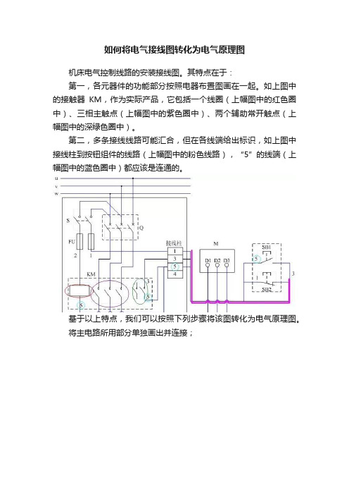
机床电气控制线路的安装接线图。
其特点在于:
第一,各元器件的功能部分按照电器布置图画在一起。
如上图中的接触器KM,作为实际产品,它包括一个线圈(上幅图中的红色圈中)、三相主触点(上幅图中的紫色圈中)、两个辅助常开触点(上幅图中的深绿色圈中)。
第二,多条接线线路可能汇合,但在各线端给出标识,如上图中接线柱到按钮组件的线路(上幅图中的粉色线路),“5”的线端(上幅图中的蓝色圈中)都应该是连通的。
基于以上特点,我们可以按照下列步骤将该图转化为电气原理图。
将主电路所用部分单独画出并连接;
将控制电路相关部分单独画出,各线端标好数字;。
- 1、下载文档前请自行甄别文档内容的完整性,平台不提供额外的编辑、内容补充、找答案等附加服务。
- 2、"仅部分预览"的文档,不可在线预览部分如存在完整性等问题,可反馈申请退款(可完整预览的文档不适用该条件!)。
- 3、如文档侵犯您的权益,请联系客服反馈,我们会尽快为您处理(人工客服工作时间:9:00-18:30)。
PowerPCB中PCB图转原理图教程
来源:深圳龙人计算机发布者:D_K_BLUE 时间:2009-5-5 阅读:10774次
PCB设计者在使用设计软件时都会用到软件的一种功能,就是PCB图转换成为原理图。
大多的PCB设计软件都会自带这种功能,比如说Protel系列软件98系列之后都能自己实现转换。
PowerPCB也有自动转换功能,但是实现过程相对复杂,下面我们就PowerPCB如何将PCB图转换成为原理图做简单介绍。
以PowerPCB提供的Pwrdemoa.pcb为例进行说明。
1.打开PCB图,选择菜单File-Report,文件类型选PowerPCB V3.0 Format Netlist ,将文件另存为Pwrdemoa.ASC。
2.启动程序Omninet for Windows,输入文件类型(Type)选Pads-PowerPCB,Input File 1里用Browse指定网络表文件的位置。
输出文件类型(Type)选EDIF。
Output File 1指定输出文件的文件名和路径。
然后点击Run(跑动的小人)。
系统弹出一个输出窗口,
点击Accept Data。
完成后点击“确定”,再点击“Done”关闭输出窗口。
退出Omninet for Windows。
3.修改EDIF网表文件,非常麻烦且容易出错的部分。
下面是网络表的一部分;
(edif (rename C_COLON_BSLTEMP_BSLPWRDEMOA_DOTEDF "C:\TEMP\PWRDEMOA.EDF") (edifVersion 2 0 0)
(edifLevel 0)
(keywordMap (keywordLevel 0))
(library MAIN_LIB
(edifLevel 0)
(technology
(numberDefinition
(scale 1 (e 1 -6)(unit distance)))
)
(cell &6167 (cellType generic)
(view NetlistView (viewType netlist)
(interface
)
)
)
(cell &6167 (cellType generic) (view NetlistView (viewType netlist) (interface
(port &1 )
(port &2 )
(port &3 )
(port &4 )
(port &5 )
(port &6 )
(port &7 )
(port &10 )
(port &13 )
(port &14 )
(port &15 )
(port &16 )
(port &17 )
(port &18 )
(port &19 )
(port &20 )
)
)
)
(cell &68HC68R2 (cellType generic) (view NetlistView (viewType netlist) (interface
(port &1 )
(port &2 )
(port &3 )
(port &4 )
(port &5 )
(port &6 )
(port &7 )
(port &8 )
)
)
)
(cell &68HC68R2 (cellType generic) (view NetlistView (viewType netlist)
(interface
)
)
)
(cell (rename NE555_MINUSSO "NE555-SO") (cellType generic)
(view NetlistView (viewType netlist)
(interface
)
)
)
(cell (rename R1_FSL4W "R1/4W") (cellType generic)
(view NetlistView (viewType netlist)
(interface
)
)
)
(cell (rename R1_FSL4W "R1/4W") (cellType generic)
(view NetlistView (viewType netlist)
(interface
(port &1 )
(port &2 )
)
)
)
检查一下有(cell…..标记的行,特别要注意红色字体部分,其Interface部分为空,在这个cell标记的前面或后面又有一个cell 行,其Interface部分包含有
(port &1)
(port & 2)
.
.
.
等内容。
就是说每种器件出现了两个cell定义。
现在要做的就是将无port内容的cell标记删除(上述EDIF文件中红色字体部分)。
PCB板中有多少种Part Type,就需要删除多少Cell标记,还要注意不要把有port内容的那些行删掉了。
多删了或者少删了都会造成网络不完整,从而丢失信息。
将修改后的EDIF文件存盘。
4 .启动E-Studio软件,打开第3步保存的EDIF文件。
5.右键点击PWRDEMOA.EDF文件,选择Generate Schamatics:系统弹出窗口。
点击确定。
6.选择菜单File-Save As,输出格式选ORCAD 9.10。
点击Save保存。
弹出窗口中点击“确定”结束。
生成的原理图已经可以在ORCAD中打开了。
图纸显得特别长。
如果PCB比较复杂,可能会出现原理图太大,以致软件都没法处理的情况。
下图只是原理图的一部分。
7.在ORCAD中打开生成的原理图,启动PCBNavigator,打开ITC连接PowerPCB。
选择菜单PCB->Compare Netlist with PCB,生成的报告文件如下:
*PADS-ECO-V3.0-MILS*
*REMARK* old file: D:\padspwr\Files\ecogtmp0.asc
*REMARK* new file: C:\TEMP\pwrdemoa.asc
*REMARK* created by ECOGEN (Version 6.0g) on 2004-10-8 21:39:40
PART DIFFERENCES
----------------
OLD DESIGN NEW DESIGN
Ref-des Part-type:Decal Ref-des Part-type:Decal
P2 CON\60P\100\ED P2 ED
J1 CON\RIB14HL J1 RIB14HL
R1 R1/4W R1 4W
R10 R1/4W R10 4W
R11 R1/4W R11 4W
R12 R1/4W R12 4W
R14 R1/4W R14 4W
R16 R1/4W R16 4W
R2 R1/4W R2 4W
R5 R1/4W R5 4W
R6 R1/4W R6 4W
R7 R1/4W R7 4W
R8 R1/4W R8 4W
R9 R1/4W R9 4W
NET DIFFERENCES
----------------
OLD DESIGN NEW DESIGN
SWAPPED GATE DIFFERENCES
------------------------
OLD DESIGN NEW DESIGN
SWAPPED PIN DIFFERENCES
------------------------
OLD DESIGN NEW DESIGN
UNMATCHED NET PINS IN OLD DESIGN
--------------------------------
UNMATCHED NET PINS IN NEW DESIGN
--------------------------------
ATTRIBUTE DIFFERENCES
---------------------
Attribute Level [ OLD DESIGN Parent -> NEW DESIGN Parent ]
Attribute Name Old Value New Value
结束语:这种方法仅适合PCB图上元件不是很多的情况下,当元件很多时,转换的原理图由于其非常庞大、网络连接及其复杂,就失去了层次和总线的概念,所有网络都是全部连接的,步方便读图,希望广大使用者注意。
