土木工程外文翻译---高层结构与钢结构
土木工程专业外文翻译--高层建筑

外文原文Tall BuildingsAlthough there have been many advancements in building construction technology in general, spectacular achievements have been made in the design and construction of ultrahigh-rise buildings.The early development of high-rise buildings began with structural steel framing. Reinforced concrete and stressed-skin tube systems have since been economically and competitively used in a number of structures for both residential and commercial purposes. The high-rise buildings ranging from 50 to 110 stories that are being built all over the United States are the result of innovations and development of new structural systems.Greater height entails increased column and beam sizes to make buildings more rigid so that under wind load they will not sway beyond an acceptable limit. Excessive lateral sway may cause serious recurring damage to partitions, ceilings, and other architectural details. In addition, excessive sway may cause discomfort to the occupants of the building because of their perception of such motion. Structural systems of reinforced concrete, as well as steel, take full advantage of the inherent potential stiffness of the total building and therefore do not require additional stiffening to limit the sway.In a steel structure, for example, the economy can be defined in terms of the total average quantity of steel per square foot of floor area of the building. Curve A in Fig. 1 represents the average unit weight of a conventional frame with increasing numbers of stories. Curve B represents the average steel weight if the frame is protected from all lateral loads. The gap between the upper boundary and the lower boundary represents the premium for height for the traditional column-and-beam frame; Structural engineers have developed structural systems with a view to eliminating this premium.Systems in steel. Tall buildings in steel developed as a result of several types of structural innovations. The innovations have been applied to the construction of both office and apartment buildings.Frames with rigid belt trusses. In order to tie the exterior columns of a frame structure to the interior vertical trusses, a system of rigid belt trusses at mid-height and at the top of the building may be used. A good example of this system is the First Wisconsin Bank Building (1974) in Milwaukee.Framed tube. The maximum efficiency of the total structure of a tall building, for bothstrength and stiffness, to resist wind load can be achieved only if all column elements can be connected to each other in such a way that the entire building acts as a hollow tube or rigid box in projecting out of the ground. This particular structural system was probably used for the first time in the 43-story reinforced concrete DeWitt Chestnut Apartment Building in Chicago. The most significant use of this system is in the twin structural steel towers of the 110-story World Trade Center building in New York.Column-diagonal truss tube. The exterior columns of a building can be spaced reasonably far apart and yet be made to work together as a tube by connecting them with. Diagonal members intersecting at the center line of the columns and beams. This simple yet extremely efficient system was used for the first time on the John Hancock Center in Chicago, using as much steel as is normally needed for a traditional story building.Fig. 1. Graphical relationship between design quantities of steel and building heights for a typical building frame. Curves A and B correspond to the boundary conditions indicated in the two building diagrams. 1 psf = 0. 048kPa.Bundled tube. With the continuing need for larger and taller buildings, the framed tube or the column-diagonal truss tube may be used in a bundled form to create larger tube envelopes while maintaining high efficiency. The i10-story Sears Roebuck Headquarters Building in Chicago has nine tubes, bundled at tile base of the building in three rows. Some of these individual tubes terminate at different heights of the building, demonstrating the unlimited architectural possibilities of this latest structural concept. The Sears tower, at a height of 1450 ft (442 m), is the world's tallest building.Stressed-skin tube system. The tube structural system was developed for improving the resistance to lateral forces (wind or earthquake) and the control of drift (lateral building movement) in high-rise building. The stressed-skin tube takes the tube system a step further. The development of the stressed-skin tube utilizes the facade of the building as a structural element which acts with the framed tube, thus providing an efficient way of resisting lateral loads in high-rise buildings, and resulting in cost-effective column-free interior space with a high ratio of net to gross floor area.Because of the contribution of the stressed-skin facade, the framed members of the tube require less mass, and are thus lighter and less expensive. All the typical columns and spandrel beams are standard rolled shapes, minimizing the use and cost of special built-up members. The depth requirement for the perimeter spandrel beams is also reduced, and the need for upset beams above floors, which would encroach on valuable space, is minimized.The structural system has been used on the 54-story One Mellon Bank Center in Pittsburgh.Systems in concrete. While tall buildings constructed of steel had an early start, development of tall buildings of reinforced concrete progressed at a fast enough rate to provide a competitive challenge to structural steel systems for both office and apartment buildings.Framed tube. As discussed above, the first framed tube concept for tall buildings was used for the 43-story DeWitt Chestnut Apartment Building. In this building, exterior columns were spaced at 5.5-ft (1.68-m) centers, and interior columns were used as needed to support the 8-in.-thick (20-cm) flat-plate concrete slabs.Tube in tube. Another system in reinforced concrete for office buildings combines the traditional shear wall construction with an exterior framed tube. The system consists of an outer framed tube of very closely spaced columns and an interior rigid shear wall tube enclosing the central service area. The system (Fig.2), known as the tube-in-tube system, made it possible to design the world's present tallest (714 ft or 218m) lightweight concrete Building in Houston)for structure of only 35 s oriel building the unit 52 —story One Shell Plaza of a traditional shear wallSystems compiling both concrete and steel have also been developed ,an example of which is the composite system developed by Skidmore ,Owings & Merrill in which an exterior closely spaced framed tube in concrete envelops an interior steel framing ,thereby combining the advantages of both reinforced concrete and structuralsteel systems.The 52—story One Shell Square Building in New Orleans is based on this system.NEW WORDS AND PHRASES1.spectacular 壮观的,惊人的,引人注意的2.sway 摇动,摇摆,歪,使倾斜3.residential 居住的,住宅的,作住家用的4.commercial 商业的,商业上的,商务的5.innovation 革新,创新,新方法,新事物6.boundary 分界线,边界7.eliminate 排除,消除,除去8.apartment 公寓住宅,单元住宅9.column 柱,支柱,圆柱,柱状物10.demonstrate 示范,证明,演示,11.project 凸出,投射,计划,工程12.stress 应力,压力13.truss 构架,桁架14.bundle 捆,束,包15.terminate 使终止,使结尾,结束16.facade (房屋的)/E 面,立面,表面17.perimeter 周,周围,周界,周长18.encroach 侵犯,侵占,蚕食19. high • rise building 高层建筑20.reinforced concrete 钢筋混凝土21 . spandrel beam 窗下墙的墙托梁22. shear wall 剪力墙中文译文高层建筑大体上建筑施工工艺学方面已经有许多进步, 在超高层的设计和施工上已经取得了惊人的成就。
土木工程专业英语课文翻译3

第三课建筑物的组成材料和不同的结构形式联合组成建筑物的各种不同部分,包括承重框架,外壳,楼板和隔墙。
建筑物也有像升降机,供暖和冷却,照明这样的与机械和电力有关的系统。
上部结构是建筑物地面以上的部分,而下部结构和基础则是建筑物地面以下的部分。
摩天大楼的出现得益于19世纪的两大发展:钢骨架结构和旅客升降机。
钢,作为一种建筑材料,源于1885年贝色麦转炉的引入。
Gustave Eiffel(1832-1932)将钢结构引入法国。
1889年巴黎展览会的塔和他为Galerie des 机械的设计表现了钢结构的灵活性。
艾菲尔铁塔高984英尺(300米),是人类建造的最高的结构,直到40年后才被美国一系列的摩天大楼超越。
第一个升降机是在1857年被Elisha Otis安装于纽约的一幢百货公司。
在1889年,Eiffel 在艾菲尔铁塔上安装了第一个大尺寸的升降机,它的水力升降机能在一个小时内运送2350个旅客到达顶点。
承重框架。
直到19世纪晚期,建筑物外墙被用作支承楼板的承重墙。
这种结构本质上一种梁柱模型,并且仍然被用于房屋框架结构。
承重墙结构由于需要巨大的墙厚而限制了建筑物的高度。
例如,芝加哥建于19世纪80年代16层的Monadnock大厦,较下层的楼板下的墙厚达5英尺(1.5米)。
在1883 年,William Le Baron Jenney (1832-1907)采用铸铁柱支撑楼板的方式以形成笼状结构。
由钢梁和钢柱组成的骨架构造最早用于1889年。
由于骨架构造,围墙变成一个“幕墙”,胜于起支撑作用。
砖石一直被用作幕墙材料,直到20世纪30年代,轻金属和玻璃幕墙开始被使用。
在钢结构引入后,建筑物的高度持续快速地增加。
在二次世界大战前,所有的高层建筑都是采用钢结构。
战后,钢材的短缺和混凝土质量的改良导致钢筋混凝土高层建筑的出现。
芝加哥的Marina塔(1962)是美国最高的混凝土建筑。
它的高度达588英尺(179米),被伦敦的高达650英尺(198米)的邮政大厦和其他塔式建筑所超越。
土木工程专业英语课文 翻译 考试必备
土木工程专业英语课文翻译The principal construction materials of earlier times were wood and masonry brick, stone, or tile, and similar materials. The courses or layers were bound together with mortar or bitumen, a tar like substance, or some other binding agent. The Greeks and Romans sometimes used iron rods or claps to strengthen their building. The columns of the Parthenon in Athens, for example, have holes drilled in them for iron bars that have now rusted away. The Romans also used a natural cement called puzzling, made from volcanic ash, that became as hard as stone under water.早期时代的主要施工材料,木材和砌体砖,石,或瓷砖,和类似的材料。
这些课程或层密切联系在一起,用砂浆或沥青,焦油一个样物质,或其他一些有约束力的代理人。
希腊人和罗马人有时用铁棍或拍手以加强其建设。
在雅典的帕台农神庙列,例如,在他们的铁钻的酒吧现在已经生锈了孔。
罗马人还使用了天然水泥称为令人费解的,由火山灰制成,变得像石头一样坚硬在水中。
Both steel and cement, the two most important construction materials of modern times, were introduced in the nineteenth century. Steel, basically an alloy of iron and a small amount of carbon had been made up to that time by a laborious process that restricted it to such special uses as sword blades. After the invention of the Bessemer process in 1856, steel was available in large quantities at low prices. The enormous advantage of steel is its tensile force which, as we have seen, tends to pull apart many materials. New alloys have further, which is a tendency for it to weaken as a result of continual changes in stress.钢铁和水泥,两个最重要的现代建筑材料,介绍了在十九世纪。
土木工程专业英语词汇(整理版)
土木工程专业英语词汇(整理版)第一部分必须掌握,第二部分尽量掌握第一部分:1 Finite Element Method 有限单元法2 专业英语 Specialty English3 水利工程 Hydraulic Engineering4 土木工程 Civil Engineering5 地下工程 Underground Engineering6 岩土工程 Geotechnical Engineering7 道路工程 Road (Highway) Engineering8 桥梁工程Bridge Engineering9 隧道工程 Tunnel Engineering10 工程力学 Engineering Mechanics11 交通工程 Traffic Engineering12 港口工程 Port Engineering13 安全性 safety17木结构 timber structure18 砌体结构 masonry structure19 混凝土结构concrete structure20 钢结构 steelstructure21 钢 - 混凝土复合结构 steel and concrete composite structure22 素混凝土 plain concrete23 钢筋混凝土reinforced concrete24 钢筋 rebar25 预应力混凝土 pre-stressed concrete26 静定结构statically determinate structure27 超静定结构 statically indeterminate structure28 桁架结构 truss structure29 空间网架结构 spatial grid structure30 近海工程 offshore engineering31 静力学 statics32运动学kinematics33 动力学dynamics34 简支梁 simply supported beam35 固定支座 fixed bearing36弹性力学 elasticity37 塑性力学 plasticity38 弹塑性力学 elaso-plasticity39 断裂力学 fracture Mechanics40 土力学 soil mechanics41 水力学 hydraulics42 流体力学 fluid mechanics精品文库43 固体力学solid mechanics44 集中力 concentrated force45 压力 pressure46 静水压力 hydrostatic pressure47 均布压力 uniform pressure48 体力 body force49 重力 gravity50 线荷载 line load51 弯矩 bending moment52 扭矩 torque53 应力 stress54 应变 stain55 正应力 normal stress56 剪应力 shearing stress57 主应力 principal stress58 变形 deformation59 内力 internal force60 偏移量挠度 deflection61 沉降settlement62 屈曲失稳 buckle63 轴力 axial force64 允许应力 allowable stress65 疲劳分析 fatigue analysis66 梁 beam67 壳 shell68 板 plate69 桥 bridge70 桩 pile71 主动土压力 active earth pressure72 被动土压力 passive earth pressure73 承载力 load-bearing capacity74 水位 water Height75 位移 displacement76 结构力学 structural mechanics77 材料力学 material mechanics78 经纬仪 altometer79 水准仪level80 学科 discipline81 子学科 sub-discipline82 期刊 journal periodical83 文献literature84 国际标准刊号ISSN International Standard Serial Number精品文库85 国际标准书号ISBN International Standard Book Number86 卷 volume87 期 number88 专著 monograph89 会议论文集 Proceeding90 学位论文 thesis dissertation91 专利 patent92 档案档案室 archive93 国际学术会议 conference94 导师 advisor95 学位论文答辩 defense of thesis96 博士研究生 doctorate student97 研究生 postgraduate98 工程索引EI Engineering Index99 科学引文索引SCI Science Citation Index100 科学技术会议论文集索引ISTP Index to Science and Tec hnology Proceedings101 题目 title102 摘要 abstract103 全文 full-text104 参考文献 reference105 联络单位、所属单位affiliation106 主题词 Subject107 关键字 keyword108 美国土木工程师协会ASCE American Society of Civil Engineers109 联邦公路总署FHWA Federal Highway Administration110 国际标准组织ISO International Standard Organization111 解析方法 analytical method112 数值方法 numerical method113 计算 computation114 说明书 instruction115 规范 Specification Code第二部分:岩土工程专业词汇1.geotechnical engineering 岩土工程2.foundation engineering 基础工程3.soil earth 土4.soil mechanics 土力学5.cyclic loading 周期荷载6.unloading 卸载7.reloading 再加载8.viscoelastic foundation 粘弹性地基9.viscous damping 粘滞阻尼10.shear modulus 剪切模量精品文库11.soil dynamics 土动力学12.stress path 应力路径13.numerical geotechanics 数值岩土力学二.土的分类1.residual soil 残积土 groundwater level 地下水位2.groundwater 地下水 groundwater table 地下水位3.clay minerals 粘土矿物4.secondary minerals 次生矿物ndslides 滑坡6.bore hole columnar section 钻孔柱状图7.engineering geologic investigation 工程地质勘察8.boulder 漂石9.cobble 卵石10.gravel 砂石11.gravelly sand 砾砂12.coarse sand 粗砂13.medium sand 中砂14.fine sand 细砂15.silty sand 粉土16.clayey soil 粘性土17.clay 粘土18.silty clay 粉质粘土19.silt 粉土20.sandy silt 砂质粉土21.clayey silt 粘质粉土22.saturated soil 饱和土23.unsaturated soil 非饱和土24.fill (soil) 填土25.overconsolidated soil 超固结土26.normally consolidated soil 正常固结土27.underconsolidated soil 欠固结土28.zonal soil 区域性土29.soft clay 软粘土30.expansive (swelling) soil 膨胀土31.peat 泥炭32.loess 黄土33.frozen soil 冻土24.degree of saturation 饱和度25.dry unit weight 干重度26.moist unit weight 湿重度45.ISSMGE=International Society for Soil Mechanics and Geotechnical Engineering 国际土力学与岩土工程学会精品文库四.渗透性和渗流1.Darcy’s law 达西定律2.piping 管涌3.flowing soil 流土4.sand boiling 砂沸5.flow net 流网6.seepage 渗透(流)7.leakage 渗流8.seepage pressure 渗透压力9.permeability 渗透性10.seepage force 渗透力11.hydraulic gradient 水力梯度12.coefficient of permeability 渗透系数五.地基应力和变形1.soft soil 软土2.(negative) skin friction of driven pile 打入桩(负)摩阻力3.effective stress 有效应力4.total stress 总应力5.field vane shear strength 十字板抗剪强度6.low activity 低活性7.sensitivity 灵敏度8.triaxial test 三轴试验9.foundation design 基础设计10.recompaction 再压缩11.bearing capacity 承载力12.soil mass 土体13.contact stress (pressure)接触应力(压力)14.concentrated load 集中荷载15.a semi-infinite elastic solid 半无限弹性体16.homogeneous 均质17.isotropic 各向同性18.strip footing 条基19.square spread footing 方形独立基础20.underlying soil (stratum strata)下卧层(土)21.dead load =sustained load 恒载持续荷载22.live load 活载23.short –term transient load 短期瞬时荷载24.long-term transient load 长期荷载25.reduced load 折算荷载26.settlement 沉降27.deformation 变形28.casing 套管精品文库29.dike=dyke 堤(防)30.clay fraction 粘粒粒组31.physical properties 物理性质32.subgrade 路基33.well-graded soil 级配良好土34.poorly-graded soil 级配不良土35.normal stresses 正应力36.shear stresses 剪应力37.principal plane 主平面38.major (intermediate minor) principal stress 最大(中、最小)主应力39.Mohr-Coulomb failure condition 摩尔-库仑破坏条件40.FEM=finite element method 有限元法41.limit equilibrium method 极限平衡法42.pore water pressure 孔隙水压力43.preconsolidation pressure 先期固结压力44.modulus of compressibility 压缩模量45.coefficent of compressibility 压缩系数pression index 压缩指数47.swelling index 回弹指数48.geostatic stress 自重应力49.additional stress 附加应力50.total stress 总应力51.final settlement 最终沉降52.slip line 滑动线六.基坑开挖与降水1 excavation 开挖(挖方)2 dewatering (基坑)降水3 failure of foundation 基坑失稳4 bracing of foundation pit 基坑围护5 bottom heave=basal heave (基坑)底隆起6 retaining wall 挡土墙7 pore-pressure distribution 孔压分布8 dewatering method 降低地下水位法9 well point system 井点系统(轻型)10 deep well point 深井点11 vacuum well point 真空井点12 braced cuts 支撑围护13 braced excavation 支撑开挖14 braced sheeting 支撑挡板七.深基础--deep foundation1.pile foundation 桩基础1)cast –in-place 灌注桩diving casting cast-in-place pile 沉管灌注桩bored pile 钻孔桩special-shaped cast-in-place pile 机控异型灌注桩piles set into rock 嵌岩灌注桩rammed bulb pile 夯扩桩2)belled pier foundation 钻孔墩基础drilled-pier foundation 钻孔扩底墩under-reamed bored pier3)precast concrete pile 预制混凝土桩4)steel pile 钢桩steel pipe pile 钢管桩steel sheet pile 钢板桩5)prestressed concrete pile 预应力混凝土桩prestressed concrete pipe pile 预应力混凝土管桩2.caisson foundation 沉井(箱)3.diaphragm wall 地下连续墙截水墙4.friction pile 摩擦桩5.end-bearing pile 端承桩6.shaft 竖井;桩身7.wave equation analysis 波动方程分析8.pile caps 承台(桩帽)9.bearing capacity of single pile 单桩承载力teral pile load test 单桩横向载荷试验11.ultimate lateral resistance of single pile 单桩横向极限承载力12.static load test of pile 单桩竖向静荷载试验13.vertical allowable load capacity 单桩竖向容许承载力14.low pile cap 低桩承台15.high-rise pile cap 高桩承台16.vertical ultimate uplift resistance of single pile 单桩抗拔极限承载力17.silent piling 静力压桩18.uplift pile 抗拔桩19.anti-slide pile 抗滑桩20.pile groups 群桩21.efficiency factor of pile groups 群桩效率系数(η)22.efficiency of pile groups 群桩效应23.dynamic pile testing 桩基动测技术24.final set 最后贯入度25.dynamic load test of pile 桩动荷载试验26.pile integrity test 桩的完整性试验27.pile head=butt 桩头28.pile tip=pile point=pile toe 桩端(头)29.pile spacing 桩距30.pile plan 桩位布置图31.arrangement of piles =pile layout 桩的布置32.group action 群桩作用33.end bearing=tip resistance 桩端阻34.skin(side) friction=shaft resistance 桩侧阻35.pile cushion 桩垫36.pile driving(by vibration) (振动)打桩37.pile pulling test 拔桩试验38.pile shoe 桩靴39.pile noise 打桩噪音40.pile rig 打桩机九.固结 consolidation1.Terzzaghi’s consolidation theory 太沙基固结理论2.Barraon’s consolidation theory 巴隆固结理论3.Biot’s consolidation theory 比奥固结理论4.over consolidation ration (OCR)超固结比5.overconsolidation soil 超固结土6.excess pore water pressure 超孔压力7.multi-dimensional consolidation 多维固结8.one-dimensional consolidation 一维固结9.primary consolidation 主固结10.secondary consolidation 次固结11.degree of consolidation 固结度12.consolidation test 固结试验13.consolidation curve 固结曲线14.time factor Tv 时间因子15.coefficient of consolidation 固结系数16.preconsolidation pressure 前期固结压力17.principle of effective stress 有效应力原理18.consolidation under K0 condition K0 固结十.抗剪强度 shear strength1.undrained shear strength 不排水抗剪强度2.residual strength 残余强度3.long-term strength 长期强度4.peak strength 峰值强度5.shear strain rate 剪切应变速率6.dilatation 剪胀7.effective stress approach of shear strength 剪胀抗剪强度有效应力法 8.total stress approach of shear strength 抗剪强度总应力法9.Mohr-Coulomb theory 莫尔-库仑理论10.angle of internal friction 内摩擦角11.cohesion 粘聚力12.failure criterion 破坏准则13.vane strength 十字板抗剪强度14.unconfined compression 无侧限抗压强度15.effective stress failure envelop 有效应力破坏包线16.effective stress strength parameter 有效应力强度参数十一.本构模型--constitutive model1.elastic model 弹性模型2.nonlinear elastic model 非线性弹性模型3.elastoplastic model 弹塑性模型4.viscoelastic model 粘弹性模型5.boundary surface model 边界面模型6.Du ncan-Chang model 邓肯-张模型7.rigid plastic model 刚塑性模型8.cap model 盖帽模型9.work softening 加工软化10.work hardening 加工硬化11.Cambridge model 剑桥模型12.ideal elastoplastic model 理想弹塑性模型13.Mohr-Coulomb yield criterion 莫尔-库仑屈服准则14.yield surface 屈服面15.elastic half-space foundation model 弹性半空间地基模型16.elastic modulus 弹性模量17.Winkler foundation model 文克尔地基模型十二.地基承载力--bearing capacity of foundation soil1.punching shear failure 冲剪破坏2.general shear failure 整体剪切破化3.local shear failure 局部剪切破坏4.state of limit equilibrium 极限平衡状态5.critical edge pressure 临塑荷载6.stability of foundation soil 地基稳定性7.ultimate bearing capacity of foundation soil 地基极限承载力8.allowable bearing capacity of foundation soil 地基容许承载力十三.土压力--earth pressure1.active earth pressure 主动土压力2.passive earth pressure 被动土压力3.earth pressure at rest 静止土压力4.Coulomb’s earth pressure theory 库仑土压力理论5.Rankine’s earth pressure theory 朗金土压力理论十四.土坡稳定分析--slope stability analysis1.angle of repose 休止角2.Bishop method 毕肖普法3.safety factor of slope 边坡稳定安全系数4.Fellenius method of slices 费纽伦斯条分法5.Swedish circle method 瑞典圆弧滑动法6.slices method 条分法十五.挡土墙--retaining wall1.stability of retaining wall 挡土墙稳定性2.foundation wall 基础墙3.counter retaining wall 扶壁式挡土墙4.cantilever retaining wall 悬臂式挡土墙5.cantilever sheet pile wall 悬臂式板桩墙6.gravity retaining wall 重力式挡土墙7.anchored plate retaining wall 锚定板挡土墙8.anchored sheet pile wall 锚定板板桩墙十六.板桩结构物--sheet pile structure1.steel sheet pile 钢板桩2.reinforced concrete sheet pile 钢筋混凝土板桩3.steel piles 钢桩4.wooden sheet pile 木板桩5.timber piles 木桩十七.浅基础--shallow foundation1.box foundation 箱型基础2.mat(raft) foundation 片筏基础3.strip foundation 条形基础4.spread footing 扩展基础pensated foundation 补偿性基础6.bearing stratum 持力层7.rigid foundation 刚性基础8.flexible foundation 柔性基础9.emxxxxbedded depth of foundation 基础埋置深度 foundation pressure 基底附加应力11.structure-foundation-soil interaction analysis 上部结构-基础-地基共同作用分析十八.土的动力性质--dynamic properties of soils1.dynamic strength of soils 动强度2.wave velocity method 波速法3.material damping 材料阻尼4.geometric damping 几何阻尼5.damping ratio 阻尼比6.initial liquefaction 初始液化7.natural period of soil site 地基固有周期8.dynamic shear modulus of soils 动剪切模量9.dynamic ma二十.地基基础抗震1.earthquake engineering 地震工程2.soil dynamics 土动力学3.duration of earthquake 地震持续时间4.earthquake response spectrum 地震反应谱5.earthquake intensity 地震烈度6.earthquake magnitude 震级7.seismic predominant period 地震卓越周期8.maximum acceleration of earthquake 地震最大加速度二十一.室内土工实验1.high pressure consolidation test 高压固结试验2.consolidation under K0 condition K0 固结试验3.falling head permeability 变水头试验4.constant head permeability 常水头渗透试验5.unconsolidated-undrained triaxial test 不固结不排水试验(UU)6.consolidated undrained triaxial test 固结不排水试验(CU)7.consolidated drained triaxial test 固结排水试验(CD)paction test 击实试验9.consolidated quick direct shear test 固结快剪试验10.quick direct shear test 快剪试验11.consolidated drained direct shear test 慢剪试验12.sieve analysis 筛分析13.geotechnical model test 土工模型试验14.centrifugal model test 离心模型试验15.direct shear apparatus 直剪仪16.direct shear test 直剪试验17.direct simple shear test 直接单剪试验18.dynamic triaxial test 三轴试验19.dynamic simple shear 动单剪20.free(resonance)vibration column test 自(共)振柱试验二十二.原位测试1.standard penetration test (SPT)标准贯入试验2.surface wave test (SWT) 表面波试验3.dynamic penetration test(DPT) 动力触探试验4.static cone penetration (SPT) 静力触探试验5.plate loading test 静力荷载试验teral load test of pile 单桩横向载荷试验7.static load test of pile 单桩竖向荷载试验8.cross-hole test 跨孔试验9.screw plate test 螺旋板载荷试验10.pressuremeter test 旁压试验11.light sounding 轻便触探试验12.deep settlement measurement 深层沉降观测13.vane shear test 十字板剪切试验14.field permeability test 现场渗透试验15.in-situ pore water pressure measurement 原位孔隙水压量测16.in-situ soil test 原位试验第一部分必须掌握,第二部分尽量掌握第一部分:1 Finite Element Method 有限单元法2 专业英语 Specialty English3 水利工程 Hydraulic Engineering4 土木工程 Civil Engineering5 地下工程 Underground Engineering6 岩土工程 Geotechnical Engineering7 道路工程 Road (Highway) Engineering8 桥梁工程Bridge Engineering9 隧道工程 Tunnel Engineering10 工程力学 Engineering Mechanics11 交通工程 Traffic Engineering12 港口工程 Port Engineering13 安全性 safety17木结构 timber structure18 砌体结构 masonry structure19 混凝土结构concrete structure20 钢结构 steelstructure21 钢 - 混凝土复合结构 steel and concrete composite structure22 素混凝土 plain concrete23 钢筋混凝土reinforced concrete24 钢筋 rebar25 预应力混凝土 pre-stressed concrete26 静定结构statically determinate structure27 超静定结构 statically indeterminate structure28 桁架结构 truss structure29 空间网架结构 spatial grid structure30 近海工程 offshore engineering31 静力学 statics32运动学kinematics33 动力学dynamics34 简支梁 simply supported beam35 固定支座 fixed bearing36弹性力学 elasticity37 塑性力学 plasticity38 弹塑性力学 elaso-plasticity39 断裂力学 fracture Mechanics40 土力学 soil mechanics精品文库41 水力学 hydraulics42 流体力学 fluid mechanics43 固体力学solid mechanics44 集中力 concentrated force45 压力 pressure46 静水压力 hydrostatic pressure47 均布压力 uniform pressure48 体力 body force49 重力 gravity50 线荷载 line load51 弯矩 bending moment52 扭矩 torque53 应力 stress54 应变 stain55 正应力 normal stress56 剪应力 shearing stress57 主应力 principal stress58 变形 deformation59 内力 internal force60 偏移量挠度 deflection61 沉降settlement62 屈曲失稳 buckle63 轴力 axial force64 允许应力 allowable stress65 疲劳分析 fatigue analysis66 梁 beam67 壳 shell68 板 plate69 桥 bridge70 桩 pile71 主动土压力 active earth pressure72 被动土压力 passive earth pressure73 承载力 load-bearing capacity74 水位 water Height75 位移 displacement76 结构力学 structural mechanics77 材料力学 material mechanics78 经纬仪 altometer79 水准仪level80 学科 discipline81 子学科 sub-discipline82 期刊 journal periodical精品文库83 文献literature84 国际标准刊号ISSN International Standard Serial Number85 国际标准书号ISBN International Standard Book Number86 卷 volume87 期 number88 专著 monograph89 会议论文集 Proceeding90 学位论文 thesis dissertation91 专利 patent92 档案档案室 archive93 国际学术会议 conference94 导师 advisor95 学位论文答辩 defense of thesis96 博士研究生 doctorate student97 研究生 postgraduate98 工程索引EI Engineering Index99 科学引文索引SCI Science Citation Index100 科学技术会议论文集索引ISTP Index to Science and Tec hnology Proceedings101 题目 title102 摘要 abstract103 全文 full-text104 参考文献 reference105 联络单位、所属单位affiliation106 主题词 Subject107 关键字 keyword108 美国土木工程师协会ASCE American Society of Civil Engineers109 联邦公路总署FHWA Federal Highway Administration110 国际标准组织ISO International Standard Organization111 解析方法 analytical method112 数值方法 numerical method113 计算 computation114 说明书 instruction115 规范 Specification Code第二部分:岩土工程专业词汇1.geotechnical engineering 岩土工程2.foundation engineering 基础工程3.soil earth 土4.soil mechanics 土力学5.cyclic loading 周期荷载6.unloading 卸载7.reloading 再加载8.viscoelastic foundation 粘弹性地基精品文库9.viscous damping 粘滞阻尼10.shear modulus 剪切模量11.soil dynamics 土动力学12.stress path 应力路径13.numerical geotechanics 数值岩土力学二.土的分类1.residual soil 残积土 groundwater level 地下水位2.groundwater 地下水 groundwater table 地下水位3.clay minerals 粘土矿物4.secondary minerals 次生矿物ndslides 滑坡6.bore hole columnar section 钻孔柱状图7.engineering geologic investigation 工程地质勘察8.boulder 漂石9.cobble 卵石10.gravel 砂石11.gravelly sand 砾砂12.coarse sand 粗砂13.medium sand 中砂14.fine sand 细砂15.silty sand 粉土16.clayey soil 粘性土17.clay 粘土18.silty clay 粉质粘土19.silt 粉土20.sandy silt 砂质粉土21.clayey silt 粘质粉土22.saturated soil 饱和土23.unsaturated soil 非饱和土24.fill (soil) 填土25.overconsolidated soil 超固结土26.normally consolidated soil 正常固结土27.underconsolidated soil 欠固结土28.zonal soil 区域性土29.soft clay 软粘土30.expansive (swelling) soil 膨胀土31.peat 泥炭32.loess 黄土33.frozen soil 冻土24.degree of saturation 饱和度25.dry unit weight 干重度26.moist unit weight 湿重度精品文库45.ISSMGE=International Society for Soil Mechanics and Geotechnical Engineering 国际土力学与岩土工程学会四.渗透性和渗流1.Darcy’s law 达西定律2.piping 管涌3.flowing soil 流土4.sand boiling 砂沸5.flow net 流网6.seepage 渗透(流)7.leakage 渗流8.seepage pressure 渗透压力9.permeability 渗透性10.seepage force 渗透力11.hydraulic gradient 水力梯度12.coefficient of permeability 渗透系数五.地基应力和变形1.soft soil 软土2.(negative) skin friction of driven pile 打入桩(负)摩阻力3.effective stress 有效应力4.total stress 总应力5.field vane shear strength 十字板抗剪强度6.low activity 低活性7.sensitivity 灵敏度8.triaxial test 三轴试验9.foundation design 基础设计10.recompaction 再压缩11.bearing capacity 承载力12.soil mass 土体13.contact stress (pressure)接触应力(压力)14.concentrated load 集中荷载15.a semi-infinite elastic solid 半无限弹性体16.homogeneous 均质17.isotropic 各向同性18.strip footing 条基19.square spread footing 方形独立基础20.underlying soil (stratum strata)下卧层(土)21.dead load =sustained load 恒载持续荷载22.live load 活载23.short –term transient load 短期瞬时荷载24.long-term transient load 长期荷载25.reduced load 折算荷载26.settlement 沉降精品文库27.deformation 变形28.casing 套管29.dike=dyke 堤(防)30.clay fraction 粘粒粒组31.physical properties 物理性质32.subgrade 路基33.well-graded soil 级配良好土34.poorly-graded soil 级配不良土35.normal stresses 正应力36.shear stresses 剪应力37.principal plane 主平面38.major (intermediate minor) principal stress 最大(中、最小)主应力39.Mohr-Coulomb failure condition 摩尔-库仑破坏条件40.FEM=finite element method 有限元法41.limit equilibrium method 极限平衡法42.pore water pressure 孔隙水压力43.preconsolidation pressure 先期固结压力44.modulus of compressibility 压缩模量45.coefficent of compressibility 压缩系数pression index 压缩指数47.swelling index 回弹指数48.geostatic stress 自重应力49.additional stress 附加应力50.total stress 总应力51.final settlement 最终沉降52.slip line 滑动线六.基坑开挖与降水1 excavation 开挖(挖方)2 dewatering (基坑)降水3 failure of foundation 基坑失稳4 bracing of foundation pit 基坑围护5 bottom heave=basal heave (基坑)底隆起6 retaining wall 挡土墙7 pore-pressure distribution 孔压分布8 dewatering method 降低地下水位法9 well point system 井点系统(轻型)10 deep well point 深井点11 vacuum well point 真空井点12 braced cuts 支撑围护13 braced excavation 支撑开挖14 braced sheeting 支撑挡板七.深基础--deep foundation1.pile foundation 桩基础1)cast –in-place 灌注桩diving casting cast-in-place pile 沉管灌注桩bored pile 钻孔桩special-shaped cast-in-place pile 机控异型灌注桩piles set into rock 嵌岩灌注桩rammed bulb pile 夯扩桩2)belled pier foundation 钻孔墩基础drilled-pier foundation 钻孔扩底墩under-reamed bored pier3)precast concrete pile 预制混凝土桩4)steel pile 钢桩steel pipe pile 钢管桩steel sheet pile 钢板桩5)prestressed concrete pile 预应力混凝土桩prestressed concrete pipe pile 预应力混凝土管桩2.caisson foundation 沉井(箱)3.diaphragm wall 地下连续墙截水墙4.friction pile 摩擦桩5.end-bearing pile 端承桩6.shaft 竖井;桩身7.wave equation analysis 波动方程分析8.pile caps 承台(桩帽)9.bearing capacity of single pile 单桩承载力teral pile load test 单桩横向载荷试验11.ultimate lateral resistance of single pile 单桩横向极限承载力12.static load test of pile 单桩竖向静荷载试验13.vertical allowable load capacity 单桩竖向容许承载力14.low pile cap 低桩承台15.high-rise pile cap 高桩承台16.vertical ultimate uplift resistance of single pile 单桩抗拔极限承载力17.silent piling 静力压桩18.uplift pile 抗拔桩19.anti-slide pile 抗滑桩20.pile groups 群桩21.efficiency factor of pile groups 群桩效率系数(η)22.efficiency of pile groups 群桩效应23.dynamic pile testing 桩基动测技术24.final set 最后贯入度25.dynamic load test of pile 桩动荷载试验26.pile integrity test 桩的完整性试验27.pile head=butt 桩头28.pile tip=pile point=pile toe 桩端(头)29.pile spacing 桩距30.pile plan 桩位布置图31.arrangement of piles =pile layout 桩的布置32.group action 群桩作用33.end bearing=tip resistance 桩端阻34.skin(side) friction=shaft resistance 桩侧阻35.pile cushion 桩垫36.pile driving(by vibration) (振动)打桩37.pile pulling test 拔桩试验38.pile shoe 桩靴39.pile noise 打桩噪音40.pile rig 打桩机九.固结 consolidation1.Terzzaghi’s consolidation theory 太沙基固结理论2.Barraon’s consolidation theory 巴隆固结理论3.Biot’s consolidation theory 比奥固结理论4.over consolidation ration (OCR)超固结比5.overconsolidation soil 超固结土6.excess pore water pressure 超孔压力7.multi-dimensional consolidation 多维固结8.one-dimensional consolidation 一维固结9.primary consolidation 主固结10.secondary consolidation 次固结11.degree of consolidation 固结度12.consolidation test 固结试验13.consolidation curve 固结曲线14.time factor Tv 时间因子15.coefficient of consolidation 固结系数16.preconsolidation pressure 前期固结压力17.principle of effective stress 有效应力原理18.consolidation under K0 condition K0 固结十.抗剪强度 shear strength1.undrained shear strength 不排水抗剪强度2.residual strength 残余强度3.long-term strength 长期强度4.peak strength 峰值强度5.shear strain rate 剪切应变速率6.dilatation 剪胀7.effective stress approach of shear strength 剪胀抗剪强度有效应力法 8.total stress approach of shear strength 抗剪强度总应力法9.Mohr-Coulomb theory 莫尔-库仑理论10.angle of internal friction 内摩擦角11.cohesion 粘聚力12.failure criterion 破坏准则13.vane strength 十字板抗剪强度14.unconfined compression 无侧限抗压强度15.effective stress failure envelop 有效应力破坏包线16.effective stress strength parameter 有效应力强度参数十一.本构模型--constitutive model1.elastic model 弹性模型2.nonlinear elastic model 非线性弹性模型3.elastoplastic model 弹塑性模型4.viscoelastic model 粘弹性模型5.boundary surface model 边界面模型6.Du ncan-Chang model 邓肯-张模型7.rigid plastic model 刚塑性模型8.cap model 盖帽模型9.work softening 加工软化10.work hardening 加工硬化11.Cambridge model 剑桥模型12.ideal elastoplastic model 理想弹塑性模型13.Mohr-Coulomb yield criterion 莫尔-库仑屈服准则14.yield surface 屈服面15.elastic half-space foundation model 弹性半空间地基模型16.elastic modulus 弹性模量17.Winkler foundation model 文克尔地基模型十二.地基承载力--bearing capacity of foundation soil1.punching shear failure 冲剪破坏2.general shear failure 整体剪切破化3.local shear failure 局部剪切破坏4.state of limit equilibrium 极限平衡状态5.critical edge pressure 临塑荷载6.stability of foundation soil 地基稳定性7.ultimate bearing capacity of foundation soil 地基极限承载力8.allowable bearing capacity of foundation soil 地基容许承载力十三.土压力--earth pressure1.active earth pressure 主动土压力2.passive earth pressure 被动土压力3.earth pressure at rest 静止土压力4.Coulomb’s earth pressure theory 库仑土压力理论5.Rankine’s earth pressure theo ry 朗金土压力理论十四.土坡稳定分析--slope stability analysis1.angle of repose 休止角2.Bishop method 毕肖普法3.safety factor of slope 边坡稳定安全系数4.Fellenius method of slices 费纽伦斯条分法5.Swedish circle method 瑞典圆弧滑动法6.slices method 条分法十五.挡土墙--retaining wall1.stability of retaining wall 挡土墙稳定性2.foundation wall 基础墙3.counter retaining wall 扶壁式挡土墙4.cantilever retaining wall 悬臂式挡土墙5.cantilever sheet pile wall 悬臂式板桩墙6.gravity retaining wall 重力式挡土墙7.anchored plate retaining wall 锚定板挡土墙8.anchored sheet pile wall 锚定板板桩墙十六.板桩结构物--sheet pile structure1.steel sheet pile 钢板桩2.reinforced concrete sheet pile 钢筋混凝土板桩3.steel piles 钢桩4.wooden sheet pile 木板桩5.timber piles 木桩十七.浅基础--shallow foundation1.box foundation 箱型基础2.mat(raft) foundation 片筏基础3.strip foundation 条形基础4.spread footing 扩展基础pensated foundation 补偿性基础6.bearing stratum 持力层7.rigid foundation 刚性基础8.flexible foundation 柔性基础9.emxxxxbedded depth of foundation 基础埋置深度 foundation pressure 基底附加应力11.structure-foundation-soil interaction analysis 上部结构-基础-地基共同作用分析十八.土的动力性质--dynamic properties of soils1.dynamic strength of soils 动强度2.wave velocity method 波速法3.material damping 材料阻尼4.geometric damping 几何阻尼5.damping ratio 阻尼比6.initial liquefaction 初始液化7.natural period of soil site 地基固有周期8.dynamic shear modulus of soils 动剪切模量9.dynamic ma二十.地基基础抗震1.earthquake engineering 地震工程2.soil dynamics 土动力学3.duration of earthquake 地震持续时间4.earthquake response spectrum 地震反应谱5.earthquake intensity 地震烈度6.earthquake magnitude 震级7.seismic predominant period 地震卓越周期8.maximum acceleration of earthquake 地震最大加速度二十一.室内土工实验1.high pressure consolidation test 高压固结试验2.consolidation under K0 condition K0 固结试验3.falling head permeability 变水头试验4.constant head permeability 常水头渗透试验5.unconsolidated-undrained triaxial test 不固结不排水试验(UU)6.consolidated undrained triaxial test 固结不排水试验(CU)7.consolidated drained triaxial test 固结排水试验(CD)paction test 击实试验9.consolidated quick direct shear test 固结快剪试验10.quick direct shear test 快剪试验11.consolidated drained direct shear test 慢剪试验12.sieve analysis 筛分析13.geotechnical model test 土工模型试验14.centrifugal model test 离心模型试验15.direct shear apparatus 直剪仪16.direct shear test 直剪试验17.direct simple shear test 直接单剪试验18.dynamic triaxial test 三轴试验19.dynamic simple shear 动单剪20.free(resonance)vibration column test 自(共)振柱试验二十二.原位测试1.standard penetration test (SPT)标准贯入试验2.surface wave test (SWT) 表面波试验3.dynamic penetration test(DPT) 动力触探试验4.static cone penetration (SPT) 静力触探试验5.plate loading test 静力荷载试验teral load test of pile 单桩横向载荷试验7.static load test of pile 单桩竖向荷载试验8.cross-hole test 跨孔试验9.screw plate test 螺旋板载荷试验10.pressuremeter test 旁压试验11.light sounding 轻便触探试验12.deep settlement measurement 深层沉降观测13.vane shear test 十字板剪切试验14.field permeability test 现场渗透试验15.in-situ pore water pressure measurement 原位孔隙水压量测16.in-situ soil test 原位试验。
土木工程外文翻译外文文献英文文献高层建筑
High-Rise BuildingsIntroductionIt is difficult to define a high-rise building . One may say that a low-rise building ranges from 1 to 2 stories . A medium-rise building probably ranges between 3 or 4 stories up to 10 or 20 stories or more .Although the basic principles of vertical and horizontal subsystem design remain the same for low- , medium- , or high-rise buildings , when a building gets high the vertical subsystems become a controlling problem for two reasons . Higher vertical loads will require larger columns , walls , and shafts . But , more significantly , the overturning moment and the shear deflections produced by lateral forces are much larger and must be carefully provided for .The vertical subsystems in a high-rise building transmit accumulated gravity load from story to story , thus requiring larger column or wall sections to support such loading . In addition these same vertical subsystems must transmit lateral loads , such as wind or seismic loads , to the foundations. However , in contrast to vertical load , lateral load effects on buildings are not linear and increase rapidly with increase in height . For example under wind load , the overturning moment at the base of buildings varies approximately as the square of a buildings may vary as the fourth power of buildings height , other things being equal. Earthquake produces an even more pronounced effect.When the structure for a low-or medium-rise building is designed for dead and live load , it is almost an inherent property that the columns , walls , and stair or elevator shafts can carry most of the horizontal forces . The problem is primarily one of shear resistance . Moderate addition bracing for rigid frames in“short”buildings can easily be provided by filling certain panels ( or even all panels ) without increasing the sizes of the columns and girders otherwise required for vertical loads.Unfortunately , this is not is for high-rise buildings because the problem is primarily resistance to moment and deflection rather than shear alone . Special structural arrangements will often have to be made and additional structural material is always required for the columns ,girders , walls , and slabs in order to made a high-rise buildings sufficiently resistant to much higher lateral deformations .As previously mentioned , the quantity of structural material required per square foot of floor of a high-rise buildings is in excess of that required for low-rise buildings . The vertical components carrying the gravity load , such as walls , columns , and shafts , will need to be strengthened over the full height of the buildings . But quantity of material required for resisting lateral forces is even more significant .With reinforced concrete , the quantity of material also increases as the number of stories increases . But here it should be noted that the increase in the weight of material added for gravity load is much more sizable than steel , whereas for wind load the increase for lateral force resistance is not that much more since the weight of a concrete buildings helps to resist overturn . On the other hand , the problem of design for earthquake forces . Additional mass in the upper floors will give rise to a greater overall lateral force under the of seismic effects .In the case of either concrete or steel design , there are certain basic principles for providing additional resistance to lateral to lateral forces and deflections in high-rise buildings without too much sacrifire in economy .1.Increase the effective width of the moment-resisting subsystems . This is very usefulbecause increasing the width will cut down the overturn force directly and will reducedeflection by the third power of the width increase , other things remaining cinstant .However , this does require that vertical components of the widened subsystem besuitably connected to actually gain this benefit.2.Design subsystems such that the components are made to interact in the most efficientmanner . For example , use truss systems with chords and diagonals efficientlystressed , place reinforcing for walls at critical locations , and optimize stiffness ratiosfor rigid frames .3.Increase the material in the most effective resisting components . For example ,materials added in the lower floors to the flanges of columns and connecting girderswill directly decrease the overall deflection and increase the moment resistancewithout contributing mass in the upper floors where the earthquake problem isaggravated .4.Arrange to have the greater part of vertical loads be carried directly on the primarymoment-resisting components . This will help stabilize the buildings against tensileoverturning forces by precompressing the major overturn-resisting components .5.The local shear in each story can be best resisted by strategic placement if solid wallsor the use of diagonal members in a vertical subsystem . Resisting these shears solelyby vertical members in bending is usually less economical , since achieving sufficientbending resistance in the columns and connecting girders will require more materialand construction energy than using walls or diagonal members .6.Sufficient horizontal diaphragm action should be provided floor . This will help tobring the various resisting elements to work together instead of separately .7.Create mega-frames by joining large vertical and horizontal components such as twoor more elevator shafts at multistory intervals with a heavy floor subsystems , or byuse of very deep girder trusses .Remember that all high-rise buildings are essentially vertical cantilevers which are supported at the ground . When the above principles are judiciously applied , structurally desirable schemes can be obtained by walls , cores , rigid frames, tubular construction , and other vertical subsystems to achieve horizontal strength and rigidity . Some of these applications will now be described in subsequent sections in the following .The vertical subsystems in a high-rise building transmit accumulated gravity load from story to story , thus requiring larger column or wall sections to support such loading . In addition these same vertical subsystems must transmit lateral loads , such as wind or seismic loads , to the foundations. However , in contrast to vertical load , lateral load effects on buildings are not linear and increase rapidly with increase in height . For example under wind load , the overturning moment at the base of buildings varies approximately as the square of a buildings may vary as the fourth power of buildings height , other things being equal. Earthquake produces an even more pronounced effect.When the structure for a low-or medium-rise building is designed for dead and live load , it is almost an inherent property that the columns , walls , and stair or elevator shafts can carry most of the horizontal forces . The problem is primarily one of shear resistance . Moderate addition bracing for rigid frames in“short”buildings can easily be provided by filling certain panels ( or even all panels ) without increasing the sizes of the columns and girders otherwise required for vertical loads.With reinforced concrete , the quantity of material also increases as the number of stories increases . But here it should be noted that the increase in the weight of material added for gravity load is much more sizable than steel , whereas for wind load the increase for lateral force resistance is not that much more since the weight of a concrete buildings helps to resist overturn . On the other hand , the problem of design for earthquake forces . Additional mass in the upper floors will give rise to a greater overall lateral force under the of seismic effects .In the case of either concrete or steel design , there are certain basic principles for providing additional resistance to lateral to lateral forces and deflections in high-rise buildings without too much sacrifire in economy . Increase the effective width of the moment-resisting subsystems . This is very useful because increasing the width will cut down the overturn force directly and will reduce deflection by the third power of the width increase , other things remaining cinstant . However , this does require that vertical components of the widened subsystem be suitably connected to actually gain this benefit.Design subsystems such that the components are made to interact in the most efficient manner .Remember that all high-rise buildings are essentially vertical cantilevers which are supported at the ground . When the above principles are judiciously applied , structurally desirable schemes can be obtained by walls , cores , rigid frames, tubular construction , and other vertical subsystems to achieve horizontal strength and rigidity . Some of these applications will now be described in subsequent sections in the following .Shear-Wall SystemsWhen shear walls are compatible with other functional requirements , they can be economically utilized to resist lateral forces in high-rise buildings . For example , apartment buildings naturally require many separation walls . When some of these are designed to be solid , they can act as shear walls to resist lateral forces and to carry the vertical load as well . For buildings up to some 20storise , the use of shear walls is common . If given sufficient length ,such walls can economically resist lateral forces up to 30 to 40 stories or more .However , shear walls can resist lateral load only the plane of the walls ( i.e.not in a diretion perpendicular to them ) . There fore ,it is always necessary to provide shear walls in two perpendicular directions can be at least in sufficient orientation so that lateral force in any direction can be resisted . In addition , that wall layout should reflect consideration of any torsional effect .In design progress , two or more shear walls can be connected to from L-shaped or channel-shaped subsystems . Indeed , internal shear walls can be connected to from a rectangular shaft that will resist lateral forces very efficiently . If all external shear walls are continuously connected , then the whole buildings acts as tube , and connected , then the whole buildings acts as a tube , and is excellent Shear-Wall Seystems resisting lateral loads and torsion .Whereas concrete shear walls are generally of solid type with openings when necessary , steel shear walls are usually made of trusses . These trusses can have single diagonals , “X”diagonals , or“K”arrangements . A trussed wall will have its members act essentially in direct tension or compression under the action of view , and they offer some opportunity and deflection-limitation point of view , and they offer some opportunity for penetration between members . Of course , the inclined members of trusses must be suitable placed so as not to interfere with requirements for wiondows and for circulation service penetrations though these walls .In many high-rise buildings , a combination of walls and shafts can offer excellent resistance to lateral forces when they are suitably located ant connected to one another . It is also desirable that the stiffness offered these subsystems be more-or-less symmertrical in all directions .Rigid-Frame SystemsIn the design of architectural buildings , rigid-frame systems for resisting vertical and lateral loads have long been accepted as an important and standard means for designing building . They are employed for low-and medium means for designing buildings . They are employed for low- and medium up to high-rise building perhaps 70 or 100 stories high . When compared to shear-wall systems , these rigid frames both within and at the outside of a buildings . They also make use of the stiffness in beams and columns that are required for the buildings in any case , but the columns are made stronger when rigidly connected to resist the lateral as well as vertical forces though frame bending .Frequently , rigid frames will not be as stiff as shear-wall construction , and therefore may produce excessive deflections for the more slender high-rise buildings designs . But because of this flexibility , they are often considered as being more ductile and thus less susceptible to catastrophic earthquake failure when compared with ( some ) shear-wall designs . For example , if over stressing occurs at certain portions of a steel rigid frame ( i.e.,near the joint ) , ductility will allow the structure as a whole to deflect a little more , but it will by no means collapse even under a much larger force than expected on the structure . For this reason , rigid-frame construction is considered by some to be a “best”seismic-resisting type for high-rise steel buildings . On the other hand ,it is also unlikely that a well-designed share-wall system would collapse.In the case of concrete rigid frames ,there is a divergence of opinion . It true that if a concrete rigid frame is designed in the conventional manner , without special care to produce higher ductility , it will not be able to withstand a catastrophic earthquake that can produce forces several times lerger than the code design earthquake forces . therefore , some believe that it may not have additional capacity possessed by steel rigid frames . But modern research and experience has indicated that concrete frames can be designed to be ductile , when sufficient stirrups and joinery reinforcement are designed in to the frame . Modern buildings codes have specifications for the so-called ductile concrete frames . However , at present , these codes often require excessive reinforcement at certain points in the frame so as to cause congestion and resultin construction difficulties 。
高层建筑与钢结构外文翻译文献
高层建筑与钢结构外文翻译文献(文档含中英文对照即英文原文和中文翻译)Talling building and Steel constructionAlthough there have been many advancements in building construction technology in general. Spectacular archievements have been made in the design and construction ofultrahigh-rise buildings.The early development of high-rise buildings began with structural steel fraing.Reinforced concrete and stressed-skin tube systems have since been economically and competitively used in a number of structures for both residential and commercial purposes.The high-rise buildings ranging from 50 to 110 stories that are being built all over the United States are the result of innovations and development of new structual systems.Greater height entails increased column and beam sizes to make buildings more rigid so that under wind load they will not sway beyond an acceptable limit.Excessive lateral sway may cause serious recurring damage to partitions,ceilings.and other architectural details. Inaddition,excessive sway may cause discomfort to the occupants of the building because theirperception of such motion.Structural systems of reinforced concrete,as well as steel,take full advantage of inherent potential stiffness of the total building and therefore require additional stiffening to limit the sway.In a steel structure,for example,the economy can be defined in terms of the total average quantity of steel per square foot of floor area of the building.Curve A in Fig .1 represents the average unit weight of a conventional frame with increasing numbers of stories. Curve B represents the average steel weight if the frame is protected from all lateral loads. The gap between the upper boundary and the lower boundary represents the premium for height for the traditional column-and-beam frame.Structural engineers have developed structural systems with a view to eliminating this premium.Systems in steel. Tall buildings in steel developed as a result of several types of structural innovations. The innovations have been applied to the construction of both office and apartment buildings.Frame with rigid belt trusses. In order to tie the exterior columns of a frame structure to the interior vertical trusses,a system of rigid belt trusses at mid-height and at the top of the building may be used. A good example of this system is the First Wisconsin Bank Building(1974) in Milwaukee.Framed tube. The maximum efficiency of the total structure of a tall building, for both strength and stiffness,to resist wind load can be achieved only if all column element can be connected to each other in such a way that the entire building acts as a hollow tube or rigid box in projecting out of the ground. This particular structural system was probably used for the first time in the 43-story reinforced concrete DeWitt Chestnut Apartment Building in Chicago. The most significant use of this system is in the twin structural steel towers of the 110-story World Trade Center building in New YorkColumn-diagonal truss tube. The exterior columns of a building can be spaced reasonably far apart and yet be made to work together as a tube by connecting them with diagonal members interesting at the centre line of the columns and beams. This simple yet extremely efficient system was used for the first time on the John Hancock Centre in Chicago, using as much steel as is normally needed for a traditional 40-story building.Bundled tube. With the continuing need for larger and taller buildings, the framed tube or the column-diagonal truss tube may be used in a bundled form to create larger tube envelopes while maintaining high efficiency. The 110-story Sears Roebuck Headquarters Building in Chicago has nine tube, bundled at the base of the building in three rows. Some of these individual tubes terminate at different heights of the building, demonstrating the unlimited architectural possibilities of this latest structural concept. The Sears tower, at a height of 1450 ft(442m), is the world’s tallest building.Stressed-skin tube system. The tube structural system was developed for improving the resistance to lateral forces (wind and earthquake) and the control of drift (lateral building movement ) in high-rise building. The stressed-skin tube takes the tube system a step further. The development of the stressed-skin tube utilizes the façade of the building as a structural element which acts with the framed tube, thus providing an efficient way of resisting lateral loads inhigh-rise buildings, and resulting in cost-effective column-free interior space with a high ratio of net to gross floor area.Because of the contribution of the stressed-skin façade, the framed members of the tube require less mass, and are thus lighter and less expensive. All the typical columns and spandrel beams are standard rolled shapes,minimizing the use and cost of special built-up members. The depth requirement for the perimeter spandrel beams is also reduced, and the need for upset beams above floors, which would encroach on valuable space, is minimized. The structural system has been used on the 54-story One Mellon Bank Center in Pittburgh.Systems in concrete. While tall buildings constructed of steel had an early start, development of tall buildings of reinforced concrete progressed at a fast enough rate to provide a competitive chanllenge to structural steel systems for both office and apartment buildings.Framed tube. As discussed above, the first framed tube concept for tall buildings was used for the 43-story DeWitt Chestnut Apartment Building. In this building ,exterior columns were spaced at 5.5ft (1.68m) centers, and interior columns were used as needed to support the 8-in .-thick (20-m) flat-plate concrete slabs.Tube in tube. Another system in reinforced concrete for office buildings combines the traditional shear wall construction with an exterior framed tube. The system consists of an outer framed tube of very closely spaced columns and an interior rigid shear wall tube enclosing thecentral service area. The system (Fig .2), known as the tube-in-tube system , made it possible to design the world’s present tall est (714ft or 218m)lightweight concrete building ( the 52-story One Shell Plaza Building in Houston) for the unit price of a traditional shear wall structure of only 35 stories.Systems combining both concrete and steel have also been developed, an examle of which is the composite system developed by skidmore, Owings &Merril in which an exterior closely spaced framed tube in concrete envelops an interior steel framing, thereby combining the advantages of both reinforced concrete and structural steel systems. The 52-story One Shell Square Building in New Orleans is based on this system.Steel construction refers to a broad range of building construction in which steel plays the leading role. Most steel construction consists of large-scale buildings or engineering works, with the steel generally in the form of beams, girders, bars, plates, and other members shaped through the hot-rolled process. Despite the increased use of other materials, steel construction remained a major outlet for the steel industries of the U.S, U.K, U.S.S.R, Japan, West German, France, and other steel producers in the 1970s.Early history. The history of steel construction begins paradoxically several decades before the introduction of the Bessemer and the Siemens-Martin (openj-hearth) processes made it possible to produce steel in quantities sufficient for structure use. Many of problems of steel construction were studied earlier in connection with iron construction, which began with the Coalbrookdale Bridge, built in cast iron over the Severn River in England in 1777. This and subsequent iron bridge work, in addition to the construction of steam boilers and iron ship hulls , spurred the development of techniques for fabricating, designing, and jioning. The advantages of iron over masonry lay in the much smaller amounts of material required. The truss form, based on the resistance of the triangle to deformation, long used in timber, was translated effectively into iron, with cast iron being used for compression members-i.e, those bearing the weight of direct loading-and wrought iron being used for tension members-i.e, those bearing the pull of suspended loading.The technique for passing iron, heated to the plastic state, between rolls to form flat and rounded bars, was developed as early as 1800;by 1819 angle irons were rolled; and in 1849 the first I beams, 17.7 feet (5.4m) long , were fabricated as roof girders for a Paris railroad station.Two years later Joseph Paxton of England built the Crystal Palace for the London Exposition of 1851. He is said to have conceived the idea of cage construction-using relatively slender iron beams as a skeleton for the glass walls of a large, open structure. Resistance to wind forces in the Crystal palace was provided by diagonal iron rods. Two feature are particularly important in the history of metal construction; first, the use of latticed girder, which are small trusses, a form first developed in timber bridges and other structures and translated into metal by Paxton ; and second, the joining of wrought-iron tension members and cast-iron compression members by means of rivets inserted while hot.In 1853 the first metal floor beams were rolled for the Cooper Union Building in New York. In the light of the principal market demand for iron beams at the time, it is not surprising that the Cooper Union beams closely resembled railroad rails.The development of the Bessemer and Siemens-Martin processes in the 1850s and 1860s suddenly open the way to the use of steel for structural purpose. Stronger than iron in both tension and compression ,the newly available metal was seized on by imaginative engineers, notably by those involved in building the great number of heavy railroad bridges then in demand in Britain, Europe, and the U.S.A notable example was the Eads Bridge, also known as the St. Louis Bridge, in St. Louis (1867-1874), in which tubular steel ribs were used to form arches with a span of more than 500ft (152.5m). In Britain, the Firth of Forth cantilever bridge (1883-90) employed tubular struts, some 12 ft (3.66m) in diameter and 350 ft (107m) long. Such bridges and other structures were important in leading to the development and enforcement of standards and codification of permissible design stresses. The lack of adequate theoretical knowledge, and even of an adequate basis for theoretical studies, limited the value of stress analysis during the early years of the 20th century,as iccasionally failures,such as that of a cantilever bridge in Quebec in 1907,revealed.But failures were rare in the metal-skeleton office buildings;the simplicity of their design proved highly practical even in the absence of sophisticated analysis techniques. Throughout the first third of the century, ordinary carbon steel, without any special alloy strengthening or hardening, was universally used.The possibilities inherent in metal construction for high-rise building was demonstrated to the world by the Paris Exposition of 1889.for which Alexandre-Gustave Eiffel, a leading Frenchbridge engineer, erected an openwork metal tower 300m (984 ft) high. Not only was theheight-more than double that of the Great Pyramid-remarkable, but the speed of erection and low cost were even more so, a small crew completed the work in a few months.The first skyscrapers. Meantime, in the United States another important development was taking place. In 1884-85 Maj. William Le Baron Jenney, a Chicago engineer , had designed the Home Insurance Building, ten stories high, with a metal skeleton. Jenney’s beams were of Bessemer steel, though his columns were cast iron. Cast iron lintels supporting masonry over window openings were, in turn, supported on the cast iron columns. Soild masonry court and party walls provided lateral support against wind loading. Within a decade the same type of construction had been used in more than 30 office buildings in Chicago and New York. Steel played a larger and larger role in these , with riveted connections for beams and columns, sometimes strengthened for wind bracing by overlaying gusset plates at the junction of vertical and horizontal members. Light masonry curtain walls, supported at each floor level, replaced the old heavy masonry curtain walls, supported at each floor level , replaced the old heavy masonry.Though the new construction form was to remain centred almost entirely in America for several decade, its impact on the steel industry was worldwide. By the last years of the 19th century, the basic structural shapes-I beams up to 20 in. ( 0.508m) in depth and Z and T shapes of lesser proportions were readily available, to combine with plates of several widths and thicknesses to make efficient members of any required size and strength. In 1885 the heaviest structural shape produced through hot-rolling weighed less than 100 pounds (45 kilograms) per foot; decade by decade this figure rose until in the 1960s it exceeded 700 pounds (320 kilograms) per foot.Coincident with the introduction of structural steel came the introduction of the Otis electric elevator in 1889. The demonstration of a safe passenger elevator, together with that of a safe and economical steel construction method, sent building heights soaring. In New York the 286-ft (87.2-m) Flatiron Building of 1902 was surpassed in 1904 by the 375-ft (115-m) Times Building ( renamed the Allied Chemical Building) , the 468-ft (143-m) City Investing Company Building in Wall Street, the 612-ft (187-m) Singer Building (1908), the 700-ft (214-m) Metropolitan Tower (1909) and, in 1913, the 780-ft (232-m) Woolworth Building.The rapid increase in height and the height-to-width ratio brought problems. To limit street congestion, building setback design was prescribed. On the technical side, the problem of lateralsupport was studied. A diagonal bracing system, such as that used in the Eiffel Tower, was not architecturally desirable in offices relying on sunlight for illumination. The answer was found in greater reliance on the bending resistance of certain individual beams and columns strategically designed into the skeletn frame, together with a high degree of rigidity sought at the junction of the beams and columns. With today’s modern interior lighting systems, however, diagonal bracing against wind loads has returned; one notable example is the John Hancock Center in Chicago, where the external X-braces form a dramatic part of the structure’s façade.World War I brought an interruption to the boom in what had come to be called skyscrapers (the origin of the word is uncertain), but in the 1920s New York saw a resumption of the height race, culminating in the Emp ire State Building in the 1931. The Empire State’s 102 stories(1,250ft. [381m]) were to keep it established as the hightest building in the world for the next 40 years. Its speed of the erection demonstrated how thoroughly the new construction technique had been mastered. A depot across the bay at Bayonne, N.J., supplied the girders by lighter and truck on a schedule operated with millitary precision; nine derricks powerde by electric hoists lifted the girders to position; an industrial-railway setup moved steel and other material on each floor. Initial connections were made by bolting , closely followed by riveting, followed by masonry and finishing. The entire job was completed in one year and 45 days.The worldwide depression of the 1930s and World War II provided another interruption to steel construction development, but at the same time the introduction of welding to replace riveting provided an important advance.Joining of steel parts by metal are welding had been successfully achieved by the end of the 19th century and was used in emergency ship repairs during World War I, but its application to construction was limited until after World War II. Another advance in the same area had been the introduction of high-strength bolts to replace rivets in field connections.Since the close of World War II, research in Europe, the U.S., and Japan has greatly extended knowledge of the behavior of different types of structural steel under varying stresses, including those exceeding the yield point, making possible more refined and systematic analysis. This in turn has led to the adoption of more liberal design codes in most countries, more imaginative design made possible by so-called plastic design ?The introduction of the computer by short-cutting tedious paperwork, made further advances and savings possible.高层结构与钢结构近年来,尽管一般的建筑结构设计取得了很大的进步,但是取得显著成绩的还要属超高层建筑结构设计。
高层结构与钢结构 土木工程毕业设计外文翻译
高层结构与钢结构土木工程毕业设计外文翻译High-rise Structure and Steel StructureAbstract:High-rise structures, with their advantages of saving space, optimizing land use, and improving urban landscape, have become a focus of architectural design. Steel structures for high-rise buildings have gradually replaced reinforced concrete structures due to their superior performance. This paper introduces the development and advantages of high-rise buildings and steel structures, discusses the design principles and construction technologies of steel structures for high-rise buildings, and presents examples of steel structure high-rise buildings both domestically and abroad. Through analysis and comparison, the advantages of steel structures for high-rise buildings are summarized, and suggestions for the future development of steel structures in high-rise buildings are proposed.Keywords: high-rise structure; steel structure; design principles; construction technologyIntroductionIn China's urbanization process, the construction of high-rise buildings has become a major trend. High-rise buildings, with their advantages of saving space, optimizing land use, and improving urban landscape, have become a focus of architectural design. Steel structures for high-rise buildings have gradually replaced reinforced concrete structures due to their superior performance. In this paper, the development and advantages of high-rise buildings and steel structures for high-rise buildings are introduced. The design principles and construction technologies of steel structures for high-rise buildings are discussed, and examples of steel structure high-rise buildings both domestically and abroad are presented. Through analysis and comparison, the advantages of steel structures for high-rise buildings are summarized, and suggestions for the future development of steel structures in high-rise buildings are proposed.Development and advantages of high-rise buildingsHigh-rise buildings are defined as buildings with more than nine floors, or buildings with a height of more than 30 meters. With the development of society, the demand for high-rise buildings has increased significantly. High-rise buildings have many advantages:1. Save land and resources. Due to the high density of the population in cities, land resources are limited. High-rise buildings save land resources while meeting the needs of people's living and working.2. Improve the urban landscape. High-rise buildings have a strong visual impact and can improve the image and style of a city.3. Enhance the effectiveness of urban transportation. High-rise buildings located near urban transportation hubs can solve the problem of commuting for a large number of people.4. Provide a sense of security. People above the ground floor have a better sense of security than those on a lower floor. High-rise buildings can serve as disaster shelters in case of natural disasters such as earthquakes, typhoons, and floods.Development and advantages of steel structures for high-rise buildingsSteel structures have become the mainstream structure for high-rise buildings due to their superior performance:1. High strength and good seismic performance. The strength and elastic modulus of steel are high, and steel structures can withstand large deformations under earthquake loads.2. Light weight and good durability. Steel structures have a low self-weight and are not susceptible to corrosion or aging.3. Construction speed and environmental protection. Steel structures are prefabricated in a factory and assembled on-site, which greatly reduces construction time and damage to the environment.Design principles of steel structures for high-rise buildingsThe design of steel structures for high-rise buildings should follow the following principles:1. Optimize the structural system. The structural system should be selected according to the characteristics of the building, and the structural layout should be optimized to reduce the structural weight and improve the stability and integrity of the structure.2. Consider the load conditions. The maximum load conditions of the building should be analyzed, and the structural elements should be designed to withstand the maximum load.3. Ensure the safety of the structure. The design should ensure the safety of the structure during construction, use, and maintenance.4. Ensure the comfort of the building. The spatial layout and structural form should be designed to ensure the comfort of the building.Construction technology of steel structures for high-rise buildingsThe construction technology of steel structures for high-rise buildings includes:1. Prefabrication technology. Steel structures are prefabricated in a factory and assembled on-site, greatly reducing construction time and improving construction efficiency.2. Modular construction technology. The modular construction technology can improve the accuracy of fabrication and reduce the difficulty of installation.3. External stress technology. The external stress technology can improve the load-carrying capacity of steel structures and reduce the deformation of the structure.Examples of steel structure high-rise buildings both domestically and abroadThere are many examples of steel structure high-rise buildings both domestically and abroad. The following are three typical examples:1. Shanghai Tower. The Shanghai Tower is a 632-meter-high steel structure building located in Lujiazui, Shanghai. It is the tallest building in China and the second-tallest building in the world.2. The Shard. The Shard is a 310-meter-high steel structure building located in London, England. It is the tallest building in the UK.3. One Bryant Park. One Bryant Park is a 366-meter-high steel structure building located in New York, USA. It is the first LEED Platinum-certified building in the US.Advantages and suggestions for the future development of steel structures for high-rise buildingsSteel structures for high-rise buildings have many advantages, including high strength, good seismic performance, light weight, good durability, construction speed, and environmental protection. However, there are still some problems that need to be solved in the future development of steel structures for high-rise buildings:1. Improve design and calculation methods for steel structures.2. Improve the connection technology of steel structures.3. Develop new types of structural systems for steel structures.4. Improve the comprehensive performance of steel structures.ConclusionHigh-rise buildings are a major trend in China's urbanization process. Steel structures for high-rise buildings have gradually replaced reinforced concrete structures due to their superior performance. The design principles and construction technologies of steel structures for high-rise buildings have been discussed, and examples of steel structure high-rise buildings both domestically and abroad have been presented. Through analysis and comparison, the advantages of steel structures for high-rise buildings have been summarized, and suggestions for the future development of steel structures in high-rise buildings have been proposed.。
土木外文翻译---高层建筑与钢结构
毕业设计外文资料翻译原文题目:Talling building and Steel construction译文题目:高层建筑与钢结构院系名称:土木建筑学院专业班级:土木工程0806班学生姓名:学号:指导教师:教师职称:副教授附件: 1.外文资料翻译译文;2.外文原文。
附件1:外文资料翻译译文高层建筑与钢结构摘要:近年来,尽管一般的建筑结构设计取得了很大的进步,但是取得显著成绩的还要属超高层建筑结构设计。
最初的高层建筑设计是从钢结构的设计开始的。
钢筋混凝土和受力外包钢筒系统运用起来是比较经济的系统,被有效地运用于大批的民用建筑和商业建筑中。
50层到100层的建筑被定义为超高层建筑。
而这种建筑在美国得到广泛的应用是由于新的结构系统的发展和创新。
关键词:高层建筑,结构设计,钢结构,发展创新,结构体系这样的高度需要增大柱和梁的尺寸,这样以来可以使建筑物更加坚固以至于在允许的限度范围内承受风荷载而不产生弯曲和倾斜。
过分的倾斜会导致建筑的隔离构件、顶棚以及其他建筑细部产生循环破坏。
除此之外,过大的摇动也会使建筑的使用者们因感觉到这样的的晃动而产生不舒服的感觉。
无论是钢筋混凝土结构系统还是钢结构系统都充分利用了整个建筑的刚度潜力,因此不能指望利用多余的刚度来限制侧向位移。
在钢结构系统设计中,经济预算是根据每平方英寸地板面积上的钢材的数量确定的。
钢结构中的体系:钢结构的高层建筑的发展是几种结构体系创新的结果。
这些创新的结构已经被广泛地应用于办公大楼和公寓建筑中。
刚性带式桁架的框架结构:为了联系框架结构的外柱和内部带式桁架,可以在建筑物的中间和顶部设置刚性带式桁架。
1974年在米望基建造的威斯康森银行大楼就是一个很好的例子。
框架筒结构:如果所有的构件都用某种方式互相联系在一起,整个建筑就像是从地面发射出的一个空心筒体或是一个刚性盒子一样。
这个时候此高层建筑的整个结构抵抗风荷载的所有强度和刚度将达到最大的效率。
这种特殊的结构体系首次被芝加哥的43层钢筋混凝土的德威特红棕色的公寓大楼所采用。
土木工程专业英语课文_翻译_考试必备

土木工程专业英语课文_翻译_考试必备土木工程专业英语课文翻译The principal construction materials of earlier times were wood and masonry brick, stone, or tile, and similar materials. The courses or layers were bound together with mortar or bitumen, a tar like substance, or some other binding agent. The Greeks and Romanssometimes used iron rods or claps to strengthen their building. The columns of the Parthenon in Athens, for example, have holes drilled in them for iron bars that have now rusted away. The Romans also used a natural cement called puzzling, made from volcanic ash, that became as hard as stone under water.早期时代的主要施工材料,木材和砌体砖,石,或瓷砖,和类似的材料。
这些课程或层密切联系在一起,用砂浆或沥青,焦油一个样物质,或其他一些有约束力的代理人。
希腊人和罗马人有时用铁棍或拍手以加强其建设。
在雅典的帕台农神庙列,例如,在他们的铁钻的酒吧现在已经生锈了孔。
罗马人还使用了天然水泥称为令人费解的,由火山灰制成,变得像石头一样坚硬在水中。
Both steel and cement, the two most important construction materials of modern times, were introduced in the nineteenth century. Steel, basically an alloy of iron and a small amount of carbon had been made up to that time by a laborious process that restricted it to such special uses as sword blades. After the invention of the Bessemer process in 1856, steel was available in large quantities at low prices. The enormous advantage of steel is its tensile force which, as we have seen,tends to pull apart many materials. New alloys have further, which is a tendency for it to weaken as a result of continual changes in stress.钢铁和水泥,两个最重要的现代建筑材料,介绍了在十九世纪。
外文翻译---高层结构与钢结构

英文译文T alling building and Steel constructionAlthough there have been many advancements in building construction technology in general. Spectacular archievements have been made in the design and construction of ultrahigh-rise buildings.The early development of high-rise buildings began with structural steel framing.Reinforced concrete and stressed-skin tube systems have since been economically and competitively used in a number of structures for both residential and commercial purposes.The high-rise buildings ranging from 50 to 110 stories that are being built all over the United States are the result of innovations and development of new structual systems.Gr eater height entails increased column and beam sizes to make buildings more rigid so that under wind load they will not sway beyond an acceptable limit.Excessive lateral sway may cause serious recurring damage to partitions,ceilings.and other architectural details. In addition,excessive sway may cause discomfort to the occupants of the building because their perception of such motion.Structural systems of reinforced concrete,as well as steel,take full advantage of inherent potential stiffness of the total building and therefore require additional stiffening to limit the sway.In a steel structure,forexample,the economy can be defined in terms of the total average quantity of steel per square foot of floor area of the building.Curve A in Fig .1 represents the average unit weight of a conventional frame with increasing numbers of stories. Curve B represents the average steel weight if the frame is protected from all lateral loads. The gap between the upper boundary and the lower boundary represents the premium for height for the traditional column-and-beamframe.Structuralengineers have developed structural systems with a view to eliminating this premium.Systems in steel. Tall buildings in steel developed as a result of several types of structural innovations. The innovations have been applied to the construction of both office and apartment buildings.Frame with rigid belt trusses. In order to tie the exterior columns of a frame structure to the interior vertical trusses,a system of rigid belt trusses at mid-height and at the top of the building may be used. A good example of this system is the FirstWisconsinBankBuilding(1974) in Milwaukee.Framed tube. The maximum efficiency of the total structure of a tall building, for both strength and stiffness,to resist wind load can be achieved only if all column element can be connected to each other in such a way that the entire building acts as a hollow tube or rigid box in projecting out of the ground. This particular structural system was probably used for the first time in the 43-story reinforced concrete DeWitt Chestnut Apartment Building in Chicago. The most significant use of this system is in the twin structural steel towers of the 110-story WorldTradeCenter building in New YorkColumn-diagonal truss tube. The exterior columns of a building can be spaced reasonably far apart and yet be made to work together as a tube by connecting them with diagonal members interesting at the centre line of the columns and beams. This simple yet extremely efficient system was used for the first time on the John Hancock Centre in Chicago, using as much steel as is normally needed for a traditional 40-story building.Bundled tube. With the continuing need for larger and taller buildings, the framed tube or the column-diagonal truss tube may be used in a bundled form to create larger tube envelopes while maintaining high efficiency. The 110-story SearsRoebuckHeadquartersBuilding in Chicago has nine tube, bundled at the base of the building in three rows. Some of these individual tubes terminate at different heights of the building, demonstrating the unlimited architectural possibilities of thislatest structural concept. The Sears tower, at a height of 1450 ft(442m), is the world’s tallest building.Stressed-skin tube system. The tube structural system was developed for improving the resistance to lateral forces (wind and earthquake) and the control of drift (lateral building movement ) in high-rise building. The stressed-skin tube takes the tube system a step further. The development of the stressed-skin tube utilizes the fa?ade of the building as a structural element which acts with the framed tube, thus providing an efficient way of resisting lateral loads in high-rise buildings, and resulting in cost-effective column-free interior space with a high ratio of net to gross floor area.Because of the contribution of the stressed-skin fa?ade, the framed members of the tube require less mass, and are thus lighter and less expensive. All the typical columns and spandrel beams are standard rolled shapes,minimizing the use and cost of special built-up members. The depth requirement for the perimeter spandrel beams is also reduced, and the need for upset beams above floors, which would encroach on valuable space, is minimized. The structural system has been used on the 54-story OneMellonBankCenter in Pittburgh.Systems in concrete.While tall buildings constructed of steel had an early start, development of tall buildings of reinforced concrete progressed at a fast enough rate to provide a competitive chanllenge to structural steel systems for both office and apartment buildings.Framed tube. As discussed above, the first framed tube concept for tall buildings was used for the 43-story DeWitt Chestnut Apartment Building. In this building ,exterior columns were spaced at 5.5ft (1.68m) centers, and interior columns were used as needed to support the 8-in . -thick (20-m) flat-plate concrete slabs.Tube in tube. Another system in reinforced concrete for office buildings combines the traditional shear wall construction with an exterior framed tube. The system consists of an outer framed tube of very closely spaced columns and an interior rigid shear wall tube enclosing the central service area. The system (Fig .2),known as the tube-in-tube system , made it possible to design the world’s present tallest (714ft or 218m)lightweight concrete building ( the 52-story One Shell Plaza Building in Houston) for the unit price of a traditional shear wall structure of only 35 stories.Systems co m bining both concrete and steel have also been developed, an examle of which is the composite system developed by skidmore, Owings &Merril in which an exterior closely spaced framed tube in concrete envelops an interior steel framing, thereby combining the advantages of both reinforced concrete and structural steel systems. The 52-story OneShellSquareBuilding in New Orleans is based on this system.Steel construction refers to a broad range of building construction in which steel plays the leading role. Most steel construction consists of large-scale buildings or engineering works, with the steel generally in the form of beams, girders, bars, plates, and other members shaped through the hot-rolled process. Despite the increased use of other materials, steel construction remained a major outlet for the steel industries of the U.S, U.K, U.S.S.R, Japan, West German, France, and other steel producers in the 1970s.Early history. The history of steel construction begins paradoxically several decades before the introduction of the Bessemer and the Siemens-Martin (openj-hearth) processes made it possible to produce steel in quantities sufficient for structure use. Many of problems of steel construction were studied earlier in connection with iron construction, which began with the CoalbrookdaleBridge, built in cast iron over the Severn River in England in 1777. This and subsequent iron bridge work, in addition to the construction of steam boilers and iron ship hulls , spurred the development of techniques for fabricating, designing, and jioning. The advantages of iron over masonry lay in the much smaller amounts of material required. The truss form, based on the resistance of the triangle to deformation, long used in timber, was translated effectively into iron, with cast iron being used for compression members-i.e, those bearing the weight of direct loading-and wrought iron being usedfor tension members-i.e, those bearing the pull of suspended loading.The technique for passing iron, heated to the plastic state, between rolls to form flat and rounded bars, was developed as early as 1800;by 1819 angle irons were rolled; and in 1849 the first I beams, 17.7 feet (5.4m) long , were fabricated as roof girders for a Paris railroad station.Two years later Joseph Paxt on of England built the CrystalPalace for the London Exposition of 1851. He is said to have conceived the idea of cage construction-using relatively slender iron beams as a skeleton for the glass walls of a large, open structure. Resistance to wind forces in the Crystal palace was provided by diagonal iron rods. Two feature are particularly important in the history of metal construction; first, the use of latticed girder, which are small trusses, a form first developed in timber bridges and other structures and translated into metal by Paxton ; and second, the joining of wrought-iron tension members and cast-iron compression members by means of rivets inserted while hot.In 1853 the first metal floor beams were rolled for the CooperUnionBuilding in New York. In the light of the principal market demand for iron beams at the time, it is not surprising that the Cooper Union beams closely resembled railroad rails.The development of the Bessemer and Siemens-Martin processes in the 1850s and 1860s suddenly open the way to the use of steel for structural purpose. Stronger than iron in both tension and compression ,the newly available metal was seized on by imaginative engineers, notably by those involved in building the great number of heavy railroad bridges then in demand in Britain, Europe, and the U.S.A notable example was the EadsBridge, also known as the St. LouisBridge, in St. Louis (1867-1874), in which tubular steel ribs were used to form arches with a span of more than 500ft (152.5m). In Britain, the Firth of Forth cantilever bridge (1883-90) employed tubular struts, some 12 ft (3.66m) in diameter and 350 ft (107m) long. Such bridges and other structures were important in leading to the development and enforcement of standards and codification of permissible design stresses. The lack of adequate theoretical knowledge, and even of an adequate basis for theoretical studies,limited the value of stress analysis during the early years of the 20th century,asiccasionallyfailures,such as that of a cantilever bridge in Quebec in 1907,revealed.But failures were rare in the metal-skeleton office buildings;the simplicity of their design proved highly practical even in the absence of sophisticated analysis techniques. Throughout the first third of the century, ordinary carbon steel, without any special alloy strengthening or hardening, was universally used.The possibilities inherent in metal construction for high-rise building was demonstrated to the world by the Paris Exposition of 1889.for which Alexandre-Gustave Eiffel, a leading French bridge engineer, erected an openwork metal tower 300m (984 ft) high. Not only was the height-more than double that of the Great Pyramid-remarkable, but the speed of erection and low cost were even more so, a small crew completed the work in a few months.The first skyscrapers. Meantime, in the United States another important development was taking place. In 1884-85 Maj. William Le Baron Jenney, a Chicagoengineer , had designed the HomeInsuranceBuilding, ten stories high, with a metal skeleton. Jenney’s beams were of Bessemer steel, though his columns were cast iron. Cast iron lintels supporting masonry over window openings were, in turn, supported on the cast iron columns. Soild masonry court and party walls provided lateral support against wind loading. Within a decade the same type of construction had been used in more than 30 office buildings in Chicago and New York. Steel played a larger and larger role in these , with riveted connections for beams and columns, sometimes strengthened for wind bracing by overlaying gusset plates at the junction of vertical and horizontal members. Light masonry curtain walls, supported at each floor level, replaced the old heavy masonry curtain walls, supported at each floor level , replaced the old heavy masonry.Though the new construction form was to remain centred almost entirely in America for several decade, its impact on the steel industry was worldwide. By the last years of the 19th century, the basic structural shapes-I beams up to 20 in. ( 0.508m) in depth and Z and T shapes of lesser proportions were readily available, tocombine with plates of several widths and thicknesses to make efficient members of any required size and strength. In 1885 the heaviest structural shape produced through hot-rolling weighed less than 100 pounds (45 kilograms) per foot; decade by decade this figure rose until in the 1960s it exceeded 700 pounds (320 kilograms) per foot.Coincident with the introduction of structural steel came the introduction of t he Otis electric elevator in 1889. The demonstration of a safe passenger elevator, together with that of a safe and economical steel construction method, sent building heights soaring. In New York the 286-ft (87.2-m) Flatiron Building of 1902 was surpassed in 1904 by the 375-ft (115-m) Times Building ( renamed the Allied Chemical Building) , the 468-ft (143-m) City Investing Company Building in Wall Street, the 612-ft (187-m) Singer Building (1908), the 700-ft (214-m) Metropolitan Tower (1909) and, in 1913, the 780-ft (232-m) Woolworth Building.The rapid increase in height and the height-to-width ratio brought problems. To limit street congestion, building setback design was prescribed. On the technical side, the problem of lateral support was studied. A diagonal bracing system, such as that used in the EiffelTower, was not architecturally desirable in offices relying on sunlight for illumination. The answer was found in greater reliance on the bending resistance of certain individual beams and columns strategically designed into the skeletn frame, together with a high degree of rigidity sought at the junction of the beams and columns. With today’s modern interior lighting systems, however, diagonal bracing against wind loads has returned; one notable example is the John Hancock Center in Chicago, where the external X-braces form a dramatic part of the structure’s fa?ade.World War I brought an interruption to the boom in what had come to be called skyscrapers (the origin of the word is uncertain), but in the 1920s New York saw a resumption of the height race, culminating in the Empire State Building in the 1931. The EmpireState’s 102 stories (1,250ft. [381m]) were to keep it established as the hightest building in the world for the next 40 years. Its speed of the erection demonstrated how thoroughly the new construction technique had been mastered. A depot across the bay at Bayonne, N.J., supplied the girders by lighter and truck on aschedule operated with millitary precision; nine derricks powerde by electric hoists lifted the girders to position; an industrial-railway setup moved steel and other material on each floor. Initial connections were made by bolting , closely followed by riveting, followed by masonry and finishing. The entire job was completed in one year and 45 days.The worldwide depression of the 1930s and World War II provided another interruption to steel construction development, but at the same time the introduction of welding to replace riveting provided an important advance.Joining of steel parts by metal are welding had been successfully achieved by the end of the 19th century and was used in emergency ship repairs during World War I, but its application to construction was limited until after World War II. Another advance in the same area had been the introduction of high-strength bolts to replace rivets in field connections.Since the close of World War II, research in Europe, the U.S., and Japan has greatly extended knowledge of the behavior of different types of structural steel under varying stresses, including those exceeding the yield point, making possible more refined and systematic analysis. This in turn has led to the adoption of more liberal design codes in most countries, more imaginative design made possible by so-called plastic design ?The introduction of the computer by short-cutting tedious paperwork, made further advances and savings possible.高层结构与钢结构近年来,尽管一般的建筑结构设计取得了很大的进步,但是取得显著成绩的还要属超高层建筑结构设计。
土木外文翻译建筑物的组成及高层结构

Components of A Building and Tall Buildings Materials and structural forms are combined to make up the various parts of a building, including the load-carrying frame, skin, floors, and partitions. The building also has mechanical and electrical systems, such as elevators, heating and cooling systems, and lighting systems. The superstructure is that part of a building above ground, and the substructure and foundation is that part of a building below ground.The skyscraper owes its existence to two developments of the 19th century: steel skeleton construction and the passenger elevator. Steel as a construction material dates from the introduction of the Bessemer converter in 1885.Gustave Eiffel (1832-1932) introduced steel construction in France. His designs for the Galerie des Machines and the Tower for the Paris Exposition of 1889 expressed the lightness of the steel framework. The Eiffel Tower, 984 feet (300 meters) high, was the tallest structure built by man and was not surpassed until 40 years later by a series of American skyscrapers.The first elevator was installed by Elisha Otis installed the first elevator in a department store in New York in 1857.In 1889; Eiffel installed the first elevators on a grand scale in the Eiffel T ower, whose hydraulic elevators could transport 2,350 passengers to the summit every hour.Load-Carrying Frame. Until the late 19th century, the exterior walls of a building were used as bearing walls to support the floors. This construction is essentially a post and lintel type, and it is still used in frame construction for houses. Bearing-wall construction limited the height of buildings because of the enormous wall thickness required;For instance, the 16-story Monadnock Building built in the 1880’s in Chicago had walls 5 feet (1.5 meters) thick at the lower floors. In 1883, William Le Baron Jenney (1832-1907) supported floors on cast-iron columns to form a cage-like construction. Skeleton construction, consisting of steel beams and columns, was first used in 1889. As a consequence of skeleton construction, the enclosing walls become a “curtain wall” rather than serving a supporting function. Masonry was the curtain wall material until the 1930’s, when light metal and glass curtain walls were used. After the introduction of buildings continued to increase rapidly.All tall buildings were built with a skeleton of steel until World War Ⅱ. After the war, the shortage of steel and the improved quality of concrete led to tall building being built of reinforced concrete. Marina Tower (1962) in Chicago is the tallest concrete building in the United States;Its height—588 feet (179 meters)—is exceeded by the 650-foot (198-meter) Post Office Tower in London and by other towers.A change in attitude about skyscraper construction has brought areturn to the use of the bearing wall. In New York City, the Columbia Broadcasting System Building, designed by Eero Saarinen in 1962, has a perimeter wall consisting of 5-foot (1.5meter) wide concrete columns spaced 10 feet (3 meters) from column center to center. This perimeter wall, in effect, constitutes a bearing wall. One reason for this trend is that stiffness against the action of wind can be economically obtained by using the walls of the building as a tube;the World Trade Center building is another example of this tube approach. In contrast, rigid frames or vertical trusses are usually provided to give lateral stability.Skin. The skin of a building consists of both transparent elements (windows) and opaque elements (walls). Windows are traditionally glass, although plastics are being used, especially in schools where breakage creates a maintenance problem. The wall elements, which are used to cover the structure and are supported by it, are built of a variety of materials: brick, precast concrete, stone, opaque glass, plastics, steel, and aluminum. Wood is used mainly in house construction;It is not generally used for commercial, industrial, or public building because of the fire hazard.Floors. The construction of the floors in a building depends on the basic structural frame that is used. In steel skeleton construction, floors are either slabs of concrete resting on steel beams or a deck consisting of corrugated steel with a concrete topping. In concreteconstruction, the floors are either slabs of concrete on concrete beams or a series of closely spaced concrete beams (ribs) in two directions topped with a thin concrete slab, giving the appearance of a waffle on its underside. The kind of floor that is used depends on the span between supporting columns or walls and the function of the space. In an apartment building, for instance, where walls and columns are spaced at 12 to 18 feet (3.7 to 5.5 meters), the most popular construction is a solid concrete slab with no beams. The underside of the slab serves as the ceiling for the space below it. Corrugated steel decks are often used in office buildings because the corrugations, when enclosed by another sheet of metal, form ducts for telephone and electrical lines.Mechanical and Electrical Systems.A modern building not only contains the space for which it is intended (office, classroom, apartment) but also contains ancillary space for mechanical and electrical systems that help to provide a comfortable environment. These ancillary spaces in a skyscraper office building may constitute 25% of the total building area. The importance of heating, ventilating, electrical, and plumbing systems in an office building is shown by the fact that 40% of the construction budget is allocated to them. Because of the increased use of sealed building with windows that cannot be opened, elaborate mechanical systems are provided for ventilation and air conditioning. Ducts and pipes carry fresh air from central fan rooms and airconditioning machinery. The ceiling, which is suspended below the upper floor construction, conceals the ductwork and contains the lighting units. Electrical wiring for power and for telephone communication may also be located in this ceiling space or may be buried in the floor construction in pipes or conduits.There have been attempts to incorporate the mechanical and electrical systems into the architecture of building by frankly expressing them;For example, the American Republic Insurance Company Building (1965) in Des Moines, Iowa, exposes both the ducts and the floor structure in an organized and elegant pattern and dispenses with the suspended ceiling. This type of approach makes it possible to reduce the cost of the building and permits innovations, such as in the span of the structure.Soils and Foundations. All building are supported on the ground, and therefore the nature of the soil becomes an extremely important consideration in the design of any building. The design of a foundation depends on many soil factors, such as type of soil, soil stratification, thickness of soil lavers and their compaction, and groundwater conditions. Soils rarely have a single composition;They generally are mixtures in layers of varying thickness. For evaluation, soils are graded according to particle size, which increases from silt to clay to sand to gravel to rock. In general, the larger particle soils will support heavierloads than the smaller ones. The hardest rock can support loads up to 100 tons per square foot(976.5 metric tons/sq meter), but the softest silt can support a load of only 0.25 ton per square foot(2.44 metric tons/sq meter). All soils beneath the surface are in a state of compaction;that is, they are under a pressure that is equal to the weight of the soil column above it. Many soils (except for most sands and gavels) exhibit elastic properties—they deform when compressed under load and rebound when the load is removed. The elasticity of soils is often time-dependent, that is, deformations of the soil occur over a length of time which may vary from minutes to years after a load is imposed. Over a period of time, a building may settle if it imposes a load on the soil greater than the natural compaction weight of the soil. Conversely, a building may heave if it imposes loads on the soil smaller than the natural compaction weight. The soil may also flow under the weight of a building;That is, it tends to be squeezed out.Due to both the compaction and flow effects, buildings tend settle. Uneven settlements, exemplified by the leaning towers in Pisa and Bologna, can have damaging effects—the building may lean, walls and partitions may crack, windows and doors may become inoperative, and, in the extreme, a building may collapse. Uniform settlements are not so serious, although extreme conditions, such as those in Mexico City, can have serious consequences. Over the past 100 years, a change in thegroundwater level there has caused some buildings to settle more than 10 feet (3 meters). Because such movements can occur during and after construction, careful analysis of the behavior of soils under a building is vital.The great variability of soils has led to a variety of solutions to the foundation problem. Where firm soil exists close to the surface, the simplest solution is to rest columns on a small slab of concrete (spread footing). Where the soil is softer, it is necessary to spread the column load over a greater area;in this case, a continuous slab of concrete(raft or mat) under the whole building is used. In cases where the soil near the surface is unable to support the weight of the building, piles of wood, steel, or concrete are driven down to firm soil.The construction of a building proceeds naturally from the foundation up to the superstructure. The design process, however, proceeds from the roof down to the foundation (in the direction of gravity). In the past, the foundation was not subject to systematic investigation. A scientific approach to the design of foundations has been developed in the 20th century. Karl Terzaghi of the United States pioneered studies that made it possible to make accurate predictions of the behavior of foundations, using the science of soil mechanics coupled with exploration and testing procedures. Foundation failures of the past, such as the classical example of the leaning tower in Pisa, have becomealmost nonexistent. Foundations still are a hidden but costly part of many buildings.Although there have been many advancements in building construction technology in general, spectacular achievements have been made in the design and construction of ultrahigh-rise buildings.The early development of high-rise buildings began with structural steel framing. Reinforced concrete and stressed-skin tube systems have since been economically and competitively used in a number of structures for both residential and commercial purposes. The high-rise buildings ranging from 50 to 110 stories that are being built all over the United States are the result of innovations and development of new structural systems.Greater height entails increased column and beam sizes to make buildings more rigid so that under wind load they will not sway beyond an acceptable limit. Excessive lateral sway may cause serious recurring damage to partitions, ceilings, and other architectural details. In addition, excessive sway may cause discomfort to the occupants of the building because of their perception of such motion. Structural systems of reinforced concrete, as well as steel, take full advantage of the inherent potential stiffness of the total building and therefore do not require additional stiffening to limit the sway.In a steel structure, for example, the economy can be defined in terms of the total average quantity of steel per square foot of floor area of the building. The gap between the upper boundary and the lower boundary represents the premium for all lateral loads. The gap between the upper boundary and the lower boundary represents the premium for height for the traditional column-and-beam frame. Structural engineers have developed structural systems with a view to eliminating this premium.Systems in steel.Tall buildings in steel developed as a result of several types of structural innovations. The innovations have been applied to the construction of both office and apartment buildings.Frames with rigid belt trusses. In order to tie the exterior columns of a frame structure to the interior vertical trusses, a system of rigid belt trusses at mid-height and at the top of the building may be used. A good example of this system is the First Wisconsin Bank Building (1974) in Milwaukee.Framed tube. The maximum efficiency of the total structure of a tall building, for both strength and stiffness, to resist wind load can be achieved only if all column elements can be connected to each other in such a way that the entire building acts as a hollow tube or rigid box in projecting out of the ground. This particular structural system wasprobably used for the first time in the 43-story reinforced concrete DeWitt Chestnut Apartment Building in Chicago. The most significant use of this system is in the twin structural steel towers of the 110-story World Trade Center building in New York.Column-diagonal truss tube.The exterior columns of a building can be spaced reasonably far apart and yet be made to work together as a tube by connecting them with diagonal members intersecting at the center line of the columns and beams. This simple yet extremely efficient system was used for the first time on the John Hancock Center in Chicago, using as much steel as is normally needed for a traditional 40-story building.Bundled tube.With the continuing need for larger and taller buildings, the framed tube or the column-diagonal truss tube may be used in a bundled form to create larger tube envelopes while maintaining high efficiency. The 110-story Sears Roebuck Headquarters Building in Chicago has nine tubes, bundled at the base of the building in three rows. Some of these individual tubes terminate at different heights of the building, demonstrating the unlimited architectural possibilities of this latest structural concept. The Sears tower, at a height of 1450 ft (442m), is the world’s tallest building.Stressed-skin tube system.The tube structural system wasdeveloped for improving the resistance to lateral forces (wind or earthquake) and the control of drift (lateral building movement) in high-rise building. The stressed-skin tube takes the tube system a step further. The development of the stressed-skin tube utilizes the facade of the building as a structural element which acts with acts with the framed tube, thus providing an efficient way of resisting lateral loads in high-rise buildings, and resulting in cost-effective column-free interior space with a high ratio of net to gross floor area.Because of the contribution of the stressed-skin facade, the framed members of the tube require less mass, and are thus lighter and less expansive. All the typical columns and spandrel beams are standard rolled shapes, minimizing the use and cost of special built-up members. The depth requirement for the perimeter spandrel beams is also reduced, and the need for upset beams above floors, which would encroach on valuable space, is minimized. The structural system has been used on the 54-story One Mellon Bank Center in Pittsburgh.Systems in concrete. While tall buildings constructed of steel had an early start, development of tall buildings of reinforced concrete progressed at a fast enough rate to provide a competitive challenge to structural steel systems for both office and apartment buildings.Framed tube. As discussed above, the first framed tube concept fortall buildings was used for the 43-story DeWitt Chestnut Apartment Building. In this building, exterior columns were spaced at 5.5-ft (1.68-m) centers, and interior columns were used as needed to support the 8-in.-thick (20-cm) flat-plate concrete slabs.Tube in tube.Another system in reinforced concrete for office buildings combines the traditional shear wall construction with an exterior framed tube. The system consists of an outer framed tube of very closely spaced columns and an interior rigid shear wall tube enclosing the central service area. The system (Fig.2), known as the tube-in-tube system, made it possible to design the world’s present tallest (714 ft or 218 m) lightweight concrete building (the 52-story One Shell Plaza Building in Houston) for the unit price of a traditional shear wall structure of only 35 stories.Systems combining both concrete and steel have also been developed, an example of which is the composite system developed by Skidmore, Owings & Merrill in which an exterior closely spaced framed tube in concrete envelops an interior steel framing, thereby combining the advantages of both reinforced concrete and structural steel systems. The 52-story One Shell Square Building in New Orleans is based on this system.出处:《土木工程专业英语》,段兵廷主编,武汉理工大学出版社建筑物的组成及高层结构材料和不同的结构形式组成建筑物各类不同部份,包括繁重框架、外壳、楼板和隔墙。
(整理)土木工程专业英语--钢结构.
钢结构专业英语术语2009-09-16 17:57acceptable quality 合格质量acceptance lot 验收批量aciera 钢材admixture 外加剂against slip coefficient between friction surface of high-strength bolted connection 高强度螺栓摩擦面抗滑移系数aggregate 骨料air content 含气量air-dried timber 气干材allowable ratio of height to sectional thickness of masonry wall orcolumn 砌体墙、柱容许高厚比allowable slenderness ratio of steel member 钢构件容许长细比allowable slenderness ratio of timber compression member 受压木构件容许长细比allowable stress range of fatigue 疲劳容许应力幅allowable ultimate tensile strain of reinforcement 钢筋拉应变限值allowable value of crack width 裂缝宽度容许值allowable value of deflection of structural member 构件挠度容许值allowable value of deflection of timber bending member 受弯木构件挠度容许值allowable value of deformation of steel member 钢构件变形容许值allowable value of deformation of structural member 构件变形容许值allowable value of drift angle of earthquake resistant structure抗震结构层间位移角限值amplified coefficient of eccentricity 偏心距增大系数anchorage 锚具anchorage length of steel bar 钢筋锚固长度approval analysis during construction stage 施工阶段验算arch 拱arch with tie rod 拉捍拱arch—shaped roof truss 拱形屋架area of shear plane 剪面面积area of transformed section 换算截面面积aseismic design 建筑抗震设计assembled monolithic concrete structure 装配整体式混凝土结构automatic welding 自动焊接auxiliary steel bar 架立钢筋Bbackfilling plate 垫板balanced depth of compression zone 界限受压区高度balanced eccentricity 界限偏心距bar splice 钢筋接头bark pocket 夹皮batten plate 缀板beam 次梁bearing plane of notch 齿承压面bearing plate 支承bearing stiffener 支承加劲bent-up steel bar 弯起钢block 砌块block masonry 砌块砌体block masonry structure 砌块砌体结构blow hole 气孔board 板材bolt 螺栓bolted connection (钢结螺栓连接bolted joint (木结螺栓连接bolted steel structure 螺栓连接钢结构bonded prestressed concrete structure 有粘结预应力混凝土结构bow 顺弯brake member 制动构件breadth of wall between windows 窗间墙宽度brick masonry 砖砌体brick masonry column 砖砌体柱brick masonry structure 砖砌体结构brick masonry wall 砖砌体墙broad—leaved wood 阔叶树材building structural materials 建筑结构材料building structural unit 建筑结构单元building structure 建筑结构built—up steel column 格构式钢柱(51 bundled tube structure 成束筒结构burn—through 烧穿butt connection 对接butt joint 对接butt weld 对接焊缝Ccalculating area of compression member 受压构件计算面积calculating overturning point 计算倾覆点calculation of load-carrying capacity of member 构件承载能力计算camber of structural member 结构构件起cantilever beam 挑梁cap of reinforced concrete column 钢筋混凝土柱帽carbonation of concrete 混凝土碳化cast-in—situ concrete slab column structure 现浇板柱结构cast-in—situ concrete structure 现浇混凝土结构cavitation 孔洞cavity wall 空斗墙cement 水泥cement content 水泥含量cement mortar 水泥砂浆characteristic value of live load on floor or roof 楼面、屋面活荷载标准值characteristic value of wind load 风荷载标准值characteristic value of concrete compressive strength混凝土轴心抗压强度标准值characteristic value of concrete tensile strength 混凝土轴心抗拉标准值characteristic value of cubic concrete compressive strength混凝土立方体抗压强度标准值characteristic value of earthquake action 地震作用标准值characteristic value of horizontal crane load 吊车水平荷载标准值characteristic value of masonry strength 砌体强度标准值characteristic value o f permanent action· 永久作用标准值characteristic value of snow load 雪荷载标准值characteristic value of strength of steel 钢材强度标准值characteristic value of strength of steel bar 钢筋强度标准值characteristic value of uniformly distributed live load均布活标载标准值characteristic value of variable action 可变作用标准值characteristic value of vertical crane load 吊车竖向荷载标准值characteristic value of material strength 材料强度标准值checking section of log structural member·,原木构件计算截面chimney 烟囱circular double—layer suspended cable 圆形双层悬索circular single—layer suspended cable 圆形单层悬索circumferential weld 环形焊缝classification for earthquake—resistance of buildings· 建筑结构抗震设防类别clear height 净高clincher 扒钉coefficient of equivalent bending moment of eccentrically loadedsteel member (beam-column) 钢压弯构件等效弯矩系数cold bend inspection of steel bar 冷弯试验cold drawn bar 冷拉钢筋cold drawn wire 冷拉钢丝cold—formed thin—walled section steel 冷弯薄壁型cold-formed thin-walled steel structure· 冷弯薄壁型钢结构cold—rolled deformed bar 冷轧带肋钢筋column bracing 柱间支撑combination value of live load on floor or roof 楼面、屋面活荷载组合值compaction 密实度compliance control 合格控制composite brick masonry member 组合砖砌体构件composite floor system 组合楼盖composite floor with profiled steel sheet 压型钢板楼板composite mortar 混合砂浆composite roof truss 组合屋架composite member 组合构件compound stirrup 复合箍筋compression member with large eccentricity· 大偏心受压构件compression member with small eccentricity· 小偏心受压构件compressive strength at an angle with slope of grain 斜纹承压强度compressive strength perpendicular to grain 横纹承压强度concentration of plastic deformation 塑性变形集中conceptual earthquake—resistant design 建筑抗震概念设计concrete 混凝土concrete column 混凝土柱concrete consistence 混凝土稠度concrete folded—plate structure 混凝土折板结构concrete foundation 混凝土基础concrete mix ratio 混凝土配合比concrete wall 混凝土墙concrete-filled steel tubular member 钢管混凝土构件conifer 针叶树材coniferous wood 针叶树材connecting plate 连接connection 连接connections of steel structure 钢结构连接connections of timber structure 木结构连接consistency of mortar 砂浆稠度constant cross—section column 等截面柱construction and examination concentrated load 施工和检修集中荷载continuous weld 连续焊缝core area of section 截面核芯面积core tube supported structure 核心筒悬挂结构corrosion of steel bar 钢筋锈蚀coupled wall 连肢墙coupler 连接器coupling wall—beam 连梁coupling wall—column... 墙肢coursing degree of mortar 砂浆分层度cover plate 盖covered electrode 焊条crack 裂缝crack resistance 抗裂度crack width 裂缝宽度crane girder 吊车梁crane load 吊车荷载creep of concrete 混凝土徐变crook 横弯cross beam 井字梁cup 翘弯curved support 弧形支座cylindrical brick arch 砖筒拱Ddecay 腐朽decay prevention of timber structure 木结构防腐defect in timber 木材缺陷deformation analysis 变形验算degree of gravity vertical for structure or structural member·结构构件垂直度degree of gravity vertical for wall surface 墙面垂直度degree of plainness for structural member 构件平整度degree of plainness for wall surface 墙面平整度depth of compression zone 受压区高度depth of neutral axis 中和轴高度depth of notch 齿深design of building structures 建筑结构设计design value of earthquake-resistant strength of materials材料抗震强度设计值design value of load—carrying capacity of memb ers· 构件承载能力设计值designations 0f steel 钢材牌号design value of material strength 材料强度设计值destructive test 破损试验detailing reinforcement 构造配筋detailing requirements 构造要求diamonding 菱形变形diaphragm 横隔板dimensional errors 尺寸偏差distribution factor of snow pressure 屋面积雪分布系数dog spike 扒钉double component concrete column 双肢柱dowelled joint 销连接down-stayed composite beam 下撑式组合粱ductile frame 延性框架dynamic design 动态设计Eearthquake-resistant design 抗震设计earthquake-resistant detailing requirements 抗震构造要effective area of fillet weld 角焊缝有效面积effective depth of section 截面有效高度effective diameter of bolt or high-strength bolt·螺栓(或高强度螺有效直径effective height 计算高度effective length 计算长度effective length of fillet weld 角焊缝有效计算长度effective length of nail 钉有效长度effective span 计算跨度effective supporting length at end of beam 梁端有效支承长度effective thickness of fillet weld 角焊缝有效厚度elastic analysis scheme 弹性方案elastic foundation beam 弹性地基梁elastic foundation plate 弹性地基板elastically supported continuous girder· 弹性支座连续梁elasticity modulus of materials 材料弹性模量elongation rate 伸长率embedded parts 预埋件enhanced coefficient of local bearing strength of materials·局部抗压强度提高系数entrapped air 含气量equilibrium moisture content 平衡含水率equivalent slenderness ratio 换算长细比equivalent uniformly distributed live load· 等效均布活荷载effective cross—section area of high-strength bolt· 高强度螺栓的有效截面积effective cross—section area of bolt 螺栓有效截面面积euler's critical load 欧拉临界力euler's critical stress 欧拉临界应力excessive penetration 塌陷Ffiber concrete 纤维混凝仁filler plate 填板门fillet weld 角焊缝final setting time 终凝时间finger joint 指接fired common brick 烧结普通砖fish eye 白点fish—belly beam 角腹式梁fissure 裂缝flexible connection 柔性连flexural rigidity of section 截面弯曲刚度flexural stiffness of member 构件抗弯刚度floor plate 楼板floor system 楼盖four sides edge supported plate 四边支承板frame structure 框架结构frame tube structure 单框筒结构frame tube structure 框架—简体结构frame with sidesway 有侧移框架frame without sidesway 无侧移框架flange plate 翼缘friction coefficient of masonry 砌体摩擦系数full degree of mortar at bed joint 砂浆饱满度function of acceptance 验收函数Ggang nail plate joint 钉板连接glue used for structural timber 木结构用胶glued joint 胶合接头glued laminated timber 层板胶合木glued laminated timber structure 层板胶合结构girder 主梁grip 夹具girth weld 环形焊groove 坡口gusset plate 节点Hhanger 吊环hanging steel bar 吊筋heartwood 心材heat tempering bar 热处理钢筋height variation factor of wind pressure 风压高度变化系数helical weld 螺旋形僻缝high—strength bolt 高强度螺栓high—strength bolt with large hexagon head 大六角头高强度螺栓high—strength bolted bearing type join 承压型高强度螺栓连接,high—strength bolted connection 高强度螺栓连接high—strength bolted friction—type joint 摩擦型高强度螺栓连接high—strength bolted steel structure 高强螺栓连接钢结构hinge support 铰轴支座hinged connection 铰接hingeless arch 无铰拱hollow brick 空心砖hollow ratio of masonry unit 块体空心率honeycomb 蜂窝hook 弯钩hoop 箍筋hot—rolled deformed bar 热轧带肋钢筋hot—rolled plain bar 热轧光圆钢筋hot-rolled section steel 热轧型hunched beam 加腋梁Iimpact toughness 冲击韧性impermeability 抗渗性inclined section 斜截面inclined stirrup 斜向箍筋incomplete penetration 未焊透incomplete fusion 未溶合incompletely filled groove 未焊满indented wire 刻痕钢丝influence coefficient for load—bearing capacity of compression member 受压构件承载能力影响系数influence coefficient for spacial action 空间性能影响系数initial control 初步控insect prevention of timber structure 木结构防虫inspection for properties of glue used in structural member结构用胶性能检验inspection for properties of masonry units 块体性能检验inspection for properties of mortar 砂浆性能检验inspection for properties of steelbar 钢筋性能检验integral prefabricated prestressed concrete slab—column structure 整体预应力板柱结构intermediate stiffener 中间加劲intermittent weld 断续焊缝Jjoint of reinforcement 钢筋接Kkey joint 键连接kinetic design 动态设计knot 节子。
土木工程(钢结构和钢筋混凝土结构)外文文献翻译
文献信息:文献标题:Recent research and design developments in steel and composite steel–concrete structures in USA(近期美国在钢结构和钢筋混凝土结构研究和设计方面的发展)国外作者:Theodore V.Galambos文献出处:《Journal of Constructional Steel Research》,2000, 55(1-3):289-303字数统计:英文4718单词,23395字符;中文7671汉字外文文献:Recent research and design developments in steel and composite steel–concrete structures in USA Abstract A brief review of the status of structural steel research in the US at the end of the Twentieth Century is presented in this paper to show that while many problems are being solved, there are new and challenging problems remaining. The chief impetus for continued research is that provided by natural disasters, such as earthquakes, tropical storms, tornadoes and floods occurring in densely populated urban areas. New materials and new experimental and computational technologies also give rise to new and exciting research problems.Keywords: Bridges; Buildings; Design; Research; Steel structures; United States of America; Seismic behavior; High-performance materials1. IntroductionThe purpose of this paper is to give a brief overview of the current developments in structural steel research in the US, and of the future directions that the structural steel engineering research may take in the coming Century. The drivingforces of research in this field are the following:•new construction methods and construction products•new materials•economic considerations•natural disastersThree of these motivations are common to all engineering developments, not just to structural engineering. However, the impetus due to natural disasters is unique to our field. Recent major natural disasters in the US, such as the Northridge earthquake in California and hurricane Andrew in Florida, have spurred much of the current research activity.The presentation here is of necessity incomplete, because the author is not aware of all research going on everywhere in the country and there is not enough space in this presentation. The overview is meant to give a general flavor of the research activities, and to show that a significant effort is going on in the US. The following is a list of 10 major topics in steel research:1.Limit States Design for bridges2.Monitoring of structural performance in the field3.Design of seismically resistant connections4.Curved girder bridgesposite columns with high-performance concrete6.Building frames with semi-rigid joints7.“Advanced Structural Analysis” for buildings8.Repair and retrofit of structures9.Steel structures with high-performance steels10.Cold-formed steel structuresThe next parts of this paper will give brief discussions on some of these topics. Several topics will then be elaborated in more detail. The paper will conclude with a look toward the future of structural steel research.2.Research on steel bridgesThe American Association of State Transportation and Highway Officials (AASHTO) is the authority that promulgates design standards for bridges in the US. In 1994 it has issued a new design specification which is a Limit States Design standard that is based on the principles of reliability theory. A great deal of work went into the development of this code in the past decade, especially on calibration and on the probabilistic evaluation of the previous specification. The code is now being implemented in the design office, together with the introduction of the Systeme Internationale units. Many questions remain open about the new method of design, and there are many new projects that deal with the reliability studies of the bridge as a system. One such current project is a study to develop probabilistic models, load factors, and rational load-combination rules for the combined effects of liveload and wind; live-load and earthquake; live-load, wind and ship collision; and ship collision, wind, and scour. There are also many field measurements of bridge behavior, using modern tools of inspection and monitoring such as acoustic emission techniques and other means of non-destructive evaluation. Such fieldwork necessitates parallel studies in the laboratory, and the evolution of ever more sophisticated high-technology data transmission methods.America has an aging steel bridge population and many problems arise from fatigue and corrosion. Fatigue studies on full-scale components of the Williamsburg Bridge in New York have recently been completed at Lehigh University. A probabilistic AASHTO bridge evaluation regulation has been in effect since 1989, and it is employed to assess the future useful life of structures using rational methods that include field observation and measurement together with probabilistic analysis. Such an activity also fosters additional research because many issues are still unresolved. One such area is the study of the shakedown of shear connectors in composite bridges. This work has been recently completed at the University of Missouri.In addition to fatigue and corrosion, the major danger to bridges is the possibility of earthquake induced damage. This also has spawned many research projects on the repair and retrofit of steel superstructures and the supporting concrete piers. Many bridges in the country are being strengthened for earthquake resistance.One area that is receiving much research attention is the strengthening of concrete piers by “jacketing” them by sheets of high-performance reinforced plastic.The previously described research deals mainly with the behavior of existing structures and the design of new bridges. However, there is also a vigorous activity on novel bridge systems. This research is centered on the application of high-performance steels for the design of innovative plate and box-girder bridges, such as corrugated webs, combinations of open and closed shapes, and longer spans for truss bridges. It should be mentioned here that, in addition to work on steel bridges, there is also very active research going on in the study of the behavior of prestressed concrete girders made from very high strength concrete. The performance and design of smaller bridges using pultruded high-performance plastic composite members is also being studied extensively at present. New continuous bridge systems with steelconcrete composite segments in both the positive moment and the negative moment regions are being considered. Several researchers have developed strong capabilities to model the three-dimensional non-linear behavior of individual plate girders, and many studies are being performed on the buckling and post-buckling characteristics of such structures. Companion experimental studies are also made, especially on members built from high-performance steels. A full-scale bridge of such steel has been designed, and will soon be constructed and then tested under traffic loading. Research efforts are also underway on the study of the fatigue of large expansion joint elements and on the fatigue of highway sign structures.The final subject to be mentioned is the resurgence of studies of composite steelconcrete horizontally curved steel girder bridges. A just completed project at the University of Minnesota monitored the stresses and the deflections in a skewed and curved bridge during all phases of construction, starting from the fabrication yard to the completed bridge. Excellent correlation was found to exist between the measured stresses and deformations and the calculated values. The stresses and deflections during construction were found to be relatively small, that is, the construction process did not cause severe trauma to the system. The bridge has now been tested under service loading, using fully loaded gravel trucks, for two years, and it will continue tobe studied for further years to measure changes in performance under service over time. A major testing project is being conducted at the Federal Highway Administration laboratory in Washington, DC, where a half-scale curved composite girder bridge is currently being tested to determine its limit states. The test-bridge was designed to act as its own test-frame, where various portions can be replaced after testing. Multiple flexure tests, shear tests, and tests under combined bending and shear, are thus performed with realistic end-conditions and restraints. The experiments are also modeled by finite element analysis to check conformance between reality and prediction. Finally design standards will be evolved from the knowledge gained. This last project is the largest bridge research project in the USA at the present time.From the discussion above it can be seen that even though there is no large expansion of the nation’s highway and railr oad system, there is extensive work going on in bridge research. The major challenge facing both the researcher and the transportation engineer is the maintenance of a healthy but aging system, seeing to its gradual replacement while keeping it safe and serviceable.3.Research on steel members and framesThere are many research studies on the strength and behavior of steel building structures. The most important of these have to do with the behavior and design of steel structures under severe seismic events. This topic will be discussed later in this paper. The most significant trends of the non-seismic research are the following: •“Advanced” methods of structural analysis and design are actively studied at many Universities, notably at Cornell, Purdue, Stanford, and Georgia Tech Universities. Such analysis methods are meant to determine the load-deformation behavior of frames up to and beyond failure, including inelastic behavior, force redistribution, plastic hinge formation, second-order effects and frame instability. When these methods are fully operational, the structure will not have to undergo a member check, because the finite element analysis of the frame automatically performs this job. In addition to the research on the best approaches to do this advanced analysis, there are also many studies on simplifications that can be easilyutilized in the design office while still maintaining the advantages of a more complex analysis. The advanced analysis method is well developed for in-plane behavior, but much work is yet to be done on the cases where bi-axial bending or lateraltorsional buckling must be considered. Some successes have been achieved, but the research is far from complete.•Another aspect of the frame behavior work is the study of the frames with semirigid joints. The American Institute of Steel construction (AISC) has published design methods for office use. Current research is concentrating on the behavior of such structures under seismic loading. It appears that it is possible to use such frames in some seismic situations, that is, frames under about 8 to 10 stories in height under moderate earthquake loads. The future of structures with semi-rigid frames looks very promising, mainly because of the efforts of researchers such as Leon at Georgia Tech University , and many others.•Research on member behavior is concerned with studying the buckling and postbuckling behavior of compact angle and wide-flange beam members by advanced commercial finite element programs. Such research is going back to examine the assumptions made in the 1950s and 1960s when the plastic design compactness and bracing requirements were first formulated on a semi-empirical basis. The non-linear finite element computations permit the “re-testing” of the old experiments a nd the performing of new computer experiments to study new types of members and new types of steels. White of Georgia Tech is one of the pioneers in this work. Some current research at the US military Academy and at the University of Minnesota by Earls is discussed later in this report. The significance of this type of research is that the phenomena of extreme yielding and distortion can be efficiently examined in parameter studies performed on the computer. The computer results can be verified with old experiments, or a small number of new experiments. These studies show a good prospect for new insights into old problems that heretofore were never fully solved.4.Research on cold-formed steel structuresNext to seismic work, the most active part of research in the US is on cold-formed steel structures. The reason for this is that the supporting industry is expanding, especially in the area of individual family dwellings. As the cost of wood goes up, steel framed houses become more and more economical. The intellectual problems of thin-walled structures buckling in multiple modes under very large deformations have attracted some of the best minds in stability research. As a consequence, many new problems have been solved: complex member stiffening systems, stability and bracing of C and Z beams, composite slabs, perforated columns, standing-seam roof systems, bracing and stability of beams with very complicated shapes, cold-formed members with steels of high yield stress-to-tensile strength ratio, and many other interesting applications. The American Iron and Steel Institute (AISI) has issued a new expanded standard in 1996 that brought many of these research results into the hands of the designer.5.Research on steel-concrete composite structuresAlmost all structural steel bridges and buildings in the US are built with composite beams or girders. In contrast, very few columns are built as composite members. The area of composite column research is very active presently to fill up the gap of technical information on the behavior of such members. The subject of steel tubes filled with high-strength concrete is especially active. One of the aims of research performed by Hajjar at the University of Minnesota is to develop a fundamental understanding of the various interacting phenomena that occur in concrete-filled columns and beam-columns under monotonic and cyclic load. The other aim is to obtain a basic understanding of the behavior of connections of wide-flange beams to concrete filled tubes.Other major research work concerns the behavior and design of built-up composite wide-flange bridge girders under both positive and negative bending. This work is performed by Frank at the University of Texas at Austin and by White ofGeorgia Tech, and it involves extensive studies of the buckling and post-buckling of thin stiffened webs. Already mentioned is the examination of the shakedown of composite bridges. The question to be answered is whether a composite bridge girder loses composite action under repeated cycles of loads which are greater than the elastic limit load and less than the plastic mechanism load. A new study has been initiated at the University of Minnesota on the interaction between a semi-rigid steel frame system and a concrete shear wall connected by stud shear connectors.6.Research on connectionsConnection research continues to interest researchers because of the great variety of joint types. The majority of the connection work is currently related to the seismic problems that will be discussed in the next section of this paper. The most interest in non-seismic connections is the characterization of the monotonic moment-rotation behavior of various types of semi-rigid joints.7.Research on structures and connections subject to seismic forcesThe most compelling driving force for the present structural steel research effort in the US was the January 17, 1994 earthquake in Northridge, California, North of Los Angeles. The major problem for steel structures was the extensive failure of prequalified welded rigid joints by brittle fracture. In over 150 buildings of one to 26 stories high there were over a thousand fractured joints. The buildings did not collapse, nor did they show any external signs of distress, and there were no human injuries or deaths. A typical joint is shown in Fig. 1.In this connection the flanges of the beams are welded to the flanges of the column by full-penetration butt welds. The webs are bolted to the beams and welded to the columns. The characteristic features of this type of connection are the backing bars at the bottom of the beam flange, and the cope-holes left open to facilitate the field welding of the beam flanges. Fractures occurred in the welds, in the beam flanges, and/or in the column flanges, sometimes penetrating into the webs.Once the problem was discovered several large research projects were initiated at various university laboratories, such as The University of California at San Diego, the University of Washington in Seattle, the University of Texas at Austin, Lehigh University at Bethlehem, Pennsylvania, and at other places. The US Government under the leadership of the Federal Emergency Management Agency (FEMA) instituted a major national research effort. The needed work was deemed so extensive that no single research agency could hope to cope with it. Consequently three California groups formed a consortium which manages the work:1.Structural Engineering Association of California2.Applied Technology Council3.California Universities for Research in Earthquake EngineeringThe first letters in the name of each agency were combined to form the acronym SAC, which is the name of the joint venture that manages the research. We shall read much from this agency as the results of the massive amounts of research performed under its aegis are being published in the next few years.The goals of the program are to develop reliable, practical and cost-effective guidelines for the identification and inspection of at-risk steel moment frame buildings, the repair or upgrading of damaged buildings, the design of new construction, and the rehabilitation of undamaged buildings. As can be seen, the scope far exceeds the narrow look at the connections only.The first phase of the research was completed at the end of 1996, and its main aim was to arrive at interim guidelines so that design work could proceed. It consisted of the following components:•A state-of-the-art assessment of knowledge on steel connections•A survey of building damage•The evaluation of ground motion•Detailed building analyses and case studies•A preliminary experimental program•Professional training and quality assurance programs•Publishing of the Interim Design GuidelinesA number of reports were issued in this first phase of the work. A partial list of these is appended at the end of this paper.During the first phase of the SAC project a series of full-scale connection tests under static and, occasionally, dynamic cyclic tests were performed. Tests were of pre-Northridge-type connections (that is, connections as they existed at the time of the earthquake), of repaired and upgraded details, and of new recommended connection details. A schematic view of the testing program is illustrated in Fig. 2. Some recommended strategies for new design are schematically shown in Fig. 3.The following possible causes, and their combinations, were found to have contributed to the connection failures:•Inadequate workmanship in the field welds•Insufficient notch-toughness of the weld metal•Stress raisers caused by t he backing bars•Lack of complete fusion near the backing bar•Weld bead sizes were too big•Slag inclusion in the weldsWhile many of the failures can be directly attributed to the welding and the material of the joints, there are more serious questions relative to the structural system that had evolved over the years mainly based on economic considerations. The structural system used relatively few rigid-frames of heavy members that were designed to absorb the seismic forces for large parts of the structure. These few lateral-force resistant frames provide insufficient redundancy. More rigid-frames with smaller members could have provided a tougher and more ductile structural system. There is a question of size effect: test results from joints of smaller members were extrapolated to joints with larger members without adequate test verification. The effect of a large initial pulse may have triggered dynamic forces that could have caused brittle fracture in joints with fracture critical details and materials. Furthermore, the yield stress of the beams was about 30 to 40% larger than the minimum specified values assumed in design, and so the connection failed before the beams, which were supposed to form plastic hinges.As can be seen, there are many possible reasons for this massive failure rate, and there is blame to go around for everyone. No doubt, the discussion about why and how the joints failed will go on for many more years. The structural system just did not measure up to demands that were more severe than expected. What should be kept in mind, however, is that no structure collapsed or caused even superficial nonstructural damage, and no person was injured or killed. In the strictest sense the structure sacrificed itself so that no physical harm was done to its users. The economic harm, of course, was enormous.Phase 2 of the SAC project started on Jan. 1, 1996 and is planned to be completed on Dec. 31, 1999. Its aims are to provide advice and guidance to code officials, designers, steel makers, welding engineers, and fabricators, in fact, to anyone connected with earthquake resistant design of steel buildings. The work includes the development of design-criteria for new buildings, and inspection, evaluation, repair and retrofit procedures for existing buildings that are at risk. A broad scope of professional issues is being examined. Ultimately, a performance-based methodology will be recommended to the professions dealing with seismic design problems. All types of moment-frame connections will be studied: bolted and welded connections, semi-rigid connections, connections made with special steels, energy-dissipating connections, etc. The research consists of many new experiments on joints, as well as a systems-reliability-based probabilistic method for optimizing the best structural design and evaluation procedures.The research work of the Phase 2 SAC Project is essentially complete as of the date of this conference (Sep. 1999). The basic analytical and experimental work consists of the following topics:•Materials and fracture issues•Welding, joining and inspection•Analysis and testing of connections•Earthquake performance of structural systems•Simulation of seismic responseData and concepts from these five teams have been absorbed and utilized by theteam working on the development of the reliability framework for performance prediction and evaluation. A number of extensive State-Of-The-Art (SOA) reports based on the research are now in the final stages of completion. The material from these SOA reports, as well as results from trial designs, cost analyses, loss analyses, and from an evaluation of social, economic and policy issues, will then be the basis of new seismic design criteria for use by building codes.Phase 2 of the SAC Project is by far the largest and most expensive cooperative structural engineering effort in the history of US structural steel research. Much is expected to come of it. The way steel structures will be designed for steel structures is going to be deeply affected. The Northridge earthquake of January 17, 1994 proved a warning and a lesson, as well as a major impetus to learn more and to apply this knowledge more effectively.8.Research on the required properties of high-performance steelsOne other example will be elaborated on a research topic that is not motivated by natural disaster but by technological development, as an illustration among many which could have been presented. Steel makers have recently developed the capability to produce so-called “high-performance” stee ls economically, and there is a desire to use these steels in civil and military construction. Such steels are of high strength, with yield points of around 500 to 700 MPa, they can be produced to a variety of weldability, corrosion and toughness characteristics. Much work has been done on these steels in Japan with their application in seismic structures in mind. Structures from a steel, HSLA80, have been extensively studied at Lehigh University in the US . The research question to be answered is not “Give n a steel of certain properties, what are the member and structural characteristics?” but “Given the desired structural characteristics, what should the properties of the steel be?”. These questions were discussed in a workshop sponsored by the US National Institute of Standards in Technology (NIST) at the University of Minnesota on July 1, 1996. The purpose of this meeting was to define the research needs to adapt the high-performance steels to the requirements of the structural design standards. Many issues were raised, but hereonly the subject of compactness and lateral bracing will be briefly touched. The shape of the stress–strain curve has a profound effect on the inelastic load-deformation behavior of members, as illustrated by the following example. The idealized form of a tensile stress–strain diagram is shown in Fig. 4. Data for four representative steels are given in Table 1. Steel A is a new steel in Japan that has very good ductility and a low yield stress-to-tensile strength ratio (yield ratio), that is, it has about the same capacity to strainharden at structural carbon steel (Steel C; Steel B is a quenched and tempered steel with a very high yield stress but a high yield ratio; Steel D is the steel HSLA80 from the research at Lehigh).The load-deflection curves in Fig. 5 were obtained from a finite element analysis using the commercial program ABAQUS. The structure was a simply supported beam under a three-point loading. Lateral bracing was provided at the end-supports and under the central load-point. The section was a W200×46 (W8×31 in US units) profile, with a flange slenderness ratio b f/t f=7.8, a web slenderness ratioof h/t w=29.9 and an unbraced length slenderness of L b/r y=71. As seen from Fig. 5, the shape of the stress–strain curve can have a tremendous difference on the inelastic rotation capacity of a structural member. The most important parameter appears to be the yield ratio and the ductility of the steel.In addition to research on the high-performance steels, new work on the definition and improvement of conventional steels is also being conducted, spurred by the realization that the physical properties of steels as they are presently being produced are quite different from the steels for which the plastic design research was done 30 years ago. The yield stress is higher and it seems that due to the rotary straightening process the larger shapes end up with zones in their cross section where the ductility is unacceptably low.Further work on this subject is being pursued by Earls at the US Military Academy and by Ricles and his co-workers at Lehigh University. More finite element analyses and laboratory experiments are being conducted to establish the desired stress–strain characteristics of high-performance steel to achieve optimal dimensions for compactness limits, so that this material can be effectively used in seismic design applications. Additional work is done on the design of the best shapes for bridgegirders, and a full-scale girder bridge will be fabricated and tested at the structural laboratory of the Federal Highway Administration at Washington, DC.9.Future directions of structural steel research and conclusionThe future holds many challenges for structural steel research. The ongoing work necessitated by the two recent earthquakes that most affected conventional design methods, namely, the Northridge earthquake in the US and the Kobe earthquake in Japan, will continue well into the first decade of the next Century. It is very likely that future disasters of this type will bring yet other problems to the steel research community. There is a profound change in the philosophy of design for disasters: we can no longer be content with saving lives only, but we must also design structures which will not be so damaged as to require extensive repairs.Another major challenge will be the emergence of many new materials such as high-performance concrete and plastic composite structures. Steel structures will continually have to face the problem of having to demonstrate viability in the marketplace. This can only be accomplished by more innovative research. Furthermore, the new comprehensive limit-states design codes which are being implemented worldwide, need research to back up the assumptions used in the theories.Specifically, the following list highlights some of the needed research in steel structures:•Systems reliability tools have been developed to a high degree of sophistication. These tools should be applied to the studies of bridge and building structures to define the optimal locations of monitoring instruments, to assess the。
土木工程专业英语-ReinforcedConcreteStructures

tension in the concrete. ➢Such a beam fails very suddenly and completely when the first crack forms. ➢In a reinforced concrete beam, steel bars(钢筋)are embedded in the
surfaces in addition to having the ability to resist gravity, wind, or seismic
loads. ➢Finally, the choice of size or shape is governed(决定)by the designer and
土木工程专业英语
Reinforced Concrete Structures 钢筋混凝土结构
➢Concrete and reinforced cmaterials in every
country. ➢In many, including the United States and Canada, reinforced concrete is a dominant(主要的)structural material in engineered construction(建造的 建筑物). ➢The universal(通用的)nature of reinforced concrete construction stems from(归因于)the wide availability of reinforcing bars(钢筋)and the constituents(组成部分)of concrete, gravel, sand, and cement, the relatively simple skills required in concrete construction(施工), and the economy (经济性)of reinforced concrete compared to other form of construction. ➢Concrete and reinforced concrete are used in bridges, buildings of all sorts ( 各 种 各 样 ) , underground structures, water tanks, television towers, offshore oil exploration and production structures(近海石油开采和生产结 构), dams, and even in ships.
土木工程专业英语段兵延

土木工程专业英语段兵延Lesson 4 Tall BuildingAlthough there have been many advancements in building construction technology in general, spectacular achievements have been made in the design and construction of ultrahigh-rise buildings(虽然在建筑施工技术中,总的来说已经有了许多进步,但是在超高层建筑的设计和施工中也取得了惊人的成就。
The early development of high-rise buildings began with structural steel framing(高层建筑的早期发展始于结构的钢框架。
Reinforced concrete and stressed-skin tube systems have since been economically and competitively used in a number of structures for both residential and commercial purposes(从那以后,钢筋混凝土和薄壳筒体体系就被竞相经济地用在了许多民用和商用结构中。
The high-rise buildings ranging from 50 to 110 stories that arebeing built all over the United States are the result of innovations and development of new structural systems(美国各地正在修建的50,110层的高层建筑是新的结构体系改革和发展的结果。
Greater height entails increased column and beam sizes to make buildings more rigid so that under wind load they will not sway beyond an acceptable limit(更大的高度需要增加柱和梁的尺寸来使建筑物的刚性更大,以便于它们在风荷载作用下不会倾斜到允许的范围之外。
土木工程常用英语术语-专业词汇

【分享】土木工程常用英语术语第一节普通术语1. 工程结构building and civil engineering structures2. 工程结构设计design of building and civil engineering structures3. 房屋建造工程building engineering5. 马路工程highway engineering6. 铁路工程railway engineering10. 建造物(构筑物)construction works11. 结构structure12. 基础foundation13. 地基foundation soil; subgrade; subbase; ground14. 木结构timber structure15. 砌体结构masonry structure16. 钢结构steel structure17.混凝土(砼)结构concrete structure以混凝土为主制作的结构。
它包括素混凝土结构、钢筋混凝土结构和预应力混凝土结构等。
18. 特种工程结构special engineering structure20.工业建造industrial building21. 民用建造civil building; civil architecture22. 马路highway24. 高速马路freeway32. 铁路车站railway station33. 港口port; harbour39. 水库reservoir40. 水工建造物hydraulic structure; marine structure; maritime construction50. 安全设施safety device第二节房屋建造结构术语第1 页/共23 页1. 混合结构mixed structure2. 板柱结构slab-colume system3. 框架结构frame structure6. 壳体结构shell structure8. 悬索结构cable-suspended structure21.9. 充气结构pneumatic structure10. 剪力墙(结构墙)结构shear wall structure在高层和多层建造中,竖向和水平作用均由钢筋混凝土或预应力混凝土墙体承受的结构。
土木工程__英文翻译__高层结构与钢结构

外文原文:Talling building and Steel constructionAlthough there have been many advancements in building construction technology in general. Spectacular archievements have been made in the design and construction of ultrahigh-rise buildings.The early development of high-rise buildings began with structural steel framing.Reinforced concrete and stressed-skin tube systems have since been economically and competitively used in a number of structures for both residential and commercial purposes.The high-rise buildings ranging from 50 to 110 stories that are being built all over the United States are the result of innovations and development of new structual systems.Greater height entails increased column and beam sizes to make buildings more rigid so that under wind load they will not sway beyond an acceptable limit.Excessive lateral sway may cause serious recurring damage to partitions,ceilings.and other architectural details. In addition,excessive sway may cause discomfort to the occupants of the building because their perception of such motion.Structural systems of reinforced concrete,as well as steel,take full advantage of inherent potential stiffness of the total building and therefore require additional stiffening to limit the sway.In a steel structure,for example,the economy can be defined in terms of the total average quantity of steel per square foot of floor area of the building.Curve A in Fig .1 represents the average unit weight of a conventional frame with increasing numbers of stories. Curve B represents the average steel weight if the frame is protected from all lateral loads. The gap between the upper boundary and the lower boundary represents the premium for height for the traditional column-and-beam frame.Structural engineers have developed structural systems with a view to eliminating this premium.Systems in steel. Tall buildings in steel developed as a result of several types of structural innovations. The innovations have been applied to the construction of both office and apartment buildings.Frame with rigid belt trusses. In order to tie the exterior columns of a frame structure to the interior vertical trusses,a system of rigid belt trusses at mid-height and at the top of the building may be used. A good example of this system is the First Wisconsin Bank Building(1974) in Milwaukee.Framed tube. The maximum efficiency of the total structure of a tall building, for both strength and stiffness,to resist wind load can be achieved only if all column element can be connected to each other in such a way that the entire building acts as a hollow tube or rigid box in projecting out of the ground. This particular structural system was probably used for the first time in the 43-story reinforced concrete DeWitt Chestnut Apartment Building in Chicago. The most significant use of this system is in the twin structural steel towers of the 110-story World Trade Center building in New York Column-diagonal truss tube. The exterior columns of a building can be spaced reasonably far apart and yet be made to work together as a tube by connecting them with diagonal members interesting at the centre line of the columns and beams. This simple yet extremely efficient system was used for the first time on the John Hancock Centre in Chicago, using as much steel as is normally needed for a traditional 40-story building.Bundled tube. With the continuing need for larger and taller buildings, the framed tube or thecolumn-diagonal truss tube may be used in a bundled form to create larger tube envelopes while maintaining high efficiency. The 110-story Sears Roebuck Headquarters Building in Chicago has nine tube, bundled at the base of the building in three rows. Some of these individual tubes terminate at different heights of the building, demonstrating the unlimited architectural possibilities of this latest structural con cept. The Sears tower, at a height of 1450 ft(442m), is the world’s tallest building.Stressed-skin tube system. The tube structural system was developed for improving the resistance to lateral forces (wind and earthquake) and the control of drift (lateral building movement ) in high-rise building. The stressed-skin tube takes the tube system a step further. The development of the stressed-skin tube utilizes the façade of the building as a structural element which acts with the framed tube, thus providing an efficient way of resisting lateral loads in high-rise buildings, and resulting in cost-effective column-free interior space with a high ratio of net to gross floor area.Because of the contribution of the stressed-skin façade, the framed members of the tube require less mass, and are thus lighter and less expensive. All the typical columns and spandrel beams are standard rolled shapes,minimizing the use and cost of special built-up members. The depth requirement for the perimeter spandrel beams is also reduced, and the need for upset beams above floors, which would encroach on valuable space, is minimized. The structural system has been used on the 54-story One Mellon Bank Center in Pittburgh.Systems in concrete. While tall buildings constructed of steel had an early start, development of tall buildings of reinforced concrete progressed at a fast enough rate to provide a competitive chanllenge to structural steel systems for both office and apartment buildings.Framed tube. As discussed above, the first framed tube concept for tall buildings was used for the 43-story DeWitt Chestnut Apartment Building. In this building ,exterior columns were spaced at 5.5ft (1.68m) centers, and interior columns were used as needed to support the 8-in . -thick (20-m) flat-plate concrete slabs.Tube in tube. Another system in reinforced concrete for office buildings combines the traditional shear wall construction with an exterior framed tube. The system consists of an outer framed tube of very closely spaced columns and an interior rigid shear wall tube enclosing the central service area. The system (Fig .2), known as the tube-in-tube system , made it possible to design the world’s present tallest (714ft or 218m)lightweight concrete building ( the 52-story One Shell Plaza Building in Houston) for the unit price of a traditional shear wall structure of only 35 stories.Systems combining both concrete and steel have also been developed, an examle of which is the composite system developed by skidmore, Owings &Merril in which an exterior closely spaced framed tube in concrete envelops an interior steel framing, thereby combining the advantages of both reinforced concrete and structural steel systems. The 52-story One Shell Square Building in New Orleans is based on this system.Steel construction refers to a broad range of building construction in which steel plays the leading role. Most steel construction consists of large-scale buildings or engineering works, with the steel generally in the form of beams, girders, bars, plates, and other members shaped through the hot-rolled process. Despite the increased use of other materials, steel construction remained a major outlet for the steel industries of the U.S, U.K, U.S.S.R, Japan, West German, France, and other steel producers in the 1970s.Early history. The history of steel construction begins paradoxically several decades before the introduction of the Bessemer and the Siemens-Martin (openj-hearth) processes made it possible toproduce steel in quantities sufficient for structure use. Many of problems of steel construction were studied earlier in connection with iron construction, which began with the Coalbrookdale Bridge, built in cast iron over the Severn River in England in 1777. This and subsequent iron bridge work, in addition to the construction of steam boilers and iron ship hulls , spurred the development of techniques for fabricating, designing, and jioning. The advantages of iron over masonry lay in the much smaller amounts of material required. The truss form, based on the resistance of the triangle to deformation, long used in timber, was translated effectively into iron, with cast iron being used for compression members-i.e, those bearing the weight of direct loading-and wrought iron being used for tension members-i.e, those bearing the pull of suspended loading.The technique for passing iron, heated to the plastic state, between rolls to form flat and rounded bars, was developed as early as 1800;by 1819 angle irons were rolled; and in 1849 the first I beams, 17.7 feet (5.4m) long , were fabricated as roof girders for a Paris railroad station.Two years later Joseph Paxton of England built the Crystal Palace for the London Exposition of 1851. He is said to have conceived the idea of cage construction-using relatively slender iron beams as a skeleton for the glass walls of a large, open structure. Resistance to wind forces in the Crystal palace was provided by diagonal iron rods. Two feature are particularly important in the history of metal construction; first, the use of latticed girder, which are small trusses, a form first developed in timber bridges and other structures and translated into metal by Paxton ; and second, the joining of wrought-iron tension members and cast-iron compression members by means of rivets inserted while hot.In 1853 the first metal floor beams were rolled for the Cooper Union Building in New York. In the light of the principal market demand for iron beams at the time, it is not surprising that the Cooper Union beams closely resembled railroad rails.The development of the Bessemer and Siemens-Martin processes in the 1850s and 1860s suddenly open the way to the use of steel for structural purpose. Stronger than iron in both tension and compression ,the newly available metal was seized on by imaginative engineers, notably by those involved in building the great number of heavy railroad bridges then in demand in Britain, Europe, and the U.S.A notable example was the Eads Bridge, also known as the St. Louis Bridge, in St. Louis (1867-1874), in which tubular steel ribs were used to form arches with a span of more than 500ft (152.5m). In Britain, the Firth of Forth cantilever bridge (1883-90) employed tubular struts, some 12 ft (3.66m) in diameter and 350 ft (107m) long. Such bridges and other structures were important in leading to the development and enforcement of standards and codification of permissible design stresses. The lack of adequate theoretical knowledge, and even of an adequate basis for theoretical studies, limited the value of stress analysis during the early years of the 20th century,as iccasionally failures,such as that of a cantilever bridge in Quebec in 1907,revealed.But failures were rare in the metal-skeleton office buildings;the simplicity of their design proved highly practical even in the absence of sophisticated analysis techniques. Throughout the first third of the century, ordinary carbon steel, without any special alloy strengthening or hardening, was universally used.The possibilities inherent in metal construction for high-rise building was demonstrated to the world by the Paris Exposition of 1889.for which Alexandre-Gustave Eiffel, a leading French bridge engineer, erected an openwork metal tower 300m (984 ft) high. Not only was the height-more than double that of the Great Pyramid-remarkable, but the speed of erection and low cost were even more so,a small crew completed the work in a few months.The first skyscrapers. Meantime, in the United States another important development was taking place. In 1884-85 Maj. William Le Baron Jenney, a Chicago engineer , had designed the Home Insurance Building, ten stories high, with a metal skeleton. Jenney’s beams were of Bessemer steel, though his columns were cast iron. Cast iron lintels supporting masonry over window openings were, in turn, supported on the cast iron columns. Soild masonry court and party walls provided lateral support against wind loading. Within a decade the same type of construction had been used in more than 30 office buildings in Chicago and New York. Steel played a larger and larger role in these , with riveted connections for beams and columns, sometimes strengthened for wind bracing by overlaying gusset plates at the junction of vertical and horizontal members. Light masonry curtain walls, supported at each floor level, replaced the old heavy masonry curtain walls, supported at each floor level , replaced the old heavy masonry.Though the new construction form was to remain centred almost entirely in America for several decade, its impact on the steel industry was worldwide. By the last years of the 19th century, the basic structural shapes-I beams up to 20 in. ( 0.508m) in depth and Z and T shapes of lesser proportions were readily available, to combine with plates of several widths and thicknesses to make efficient members of any required size and strength. In 1885 the heaviest structural shape produced through hot-rolling weighed less than 100 pounds (45 kilograms) per foot; decade by decade this figure rose until in the 1960s it exceeded 700 pounds (320 kilograms) per foot.Coincident with the introduction of structural steel came the introduction of the Otis electric elevator in 1889. The demonstration of a safe passenger elevator, together with that of a safe and economical steel construction method, sent building heights soaring. In New York the 286-ft (87.2-m) Flatiron Building of 1902 was surpassed in 1904 by the 375-ft (115-m) Times Building ( renamed the Allied Chemical Building) , the 468-ft (143-m) City Investing Company Building in Wall Street, the 612-ft (187-m) Singer Building (1908), the 700-ft (214-m) Metropolitan Tower (1909) and, in 1913, the 780-ft (232-m) Woolworth Building.The rapid increase in height and the height-to-width ratio brought problems. To limit street congestion, building setback design was prescribed. On the technical side, the problem of lateral support was studied. A diagonal bracing system, such as that used in the Eiffel Tower, was not architecturally desirable in offices relying on sunlight for illumination. The answer was found in greater reliance on the bending resistance of certain individual beams and columns strategically designed into the skeletn frame, together with a high degree of rigidity sought at the junction of the beams and columns. With today’s modern interior lighting sys tems, however, diagonal bracing against wind loads has returned; one notable example is the John Hancock Center in Chicago, where the external X-braces form a dramatic part of the structure’s façade.World War I brought an interruption to the boom in what had come to be called skyscrapers (the origin of the word is uncertain), but in the 1920s New York saw a resumption of the height race, culminating in the Empire State Building in the 1931. The Empi re State’s 102 stories (1,250ft. [381m]) were to keep it established as the hightest building in the world for the next 40 years. Its speed of the erection demonstrated how thoroughly the new construction technique had been mastered. A depot across the bay at Bayonne, N.J., supplied the girders by lighter and truck on a schedule operated with millitary precision; nine derricks powerde by electric hoists lifted the girders to position; an industrial-railway setup moved steel and other material on each floor. Initial connections were made bybolting , closely followed by riveting, followed by masonry and finishing. The entire job was completed in one year and 45 days.The worldwide depression of the 1930s and World War II provided another interruption to steel construction development, but at the same time the introduction of welding to replace riveting provided an important advance.Joining of steel parts by metal are welding had been successfully achieved by the end of the 19th century and was used in emergency ship repairs during World War I, but its application to construction was limited until after World War II. Another advance in the same area had been the introduction of high-strength bolts to replace rivets in field connections.Since the close of World War II, research in Europe, the U.S., and Japan has greatly extended knowledge of the behavior of different types of structural steel under varying stresses, including those exceeding the yield point, making possible more refined and systematic analysis. This in turn has led to the adoption of more liberal design codes in most countries, more imaginative design made possible by so-called plastic design ?The introduction of the computer by short-cutting tedious paperwork, made further advances and savings possible.高层结构与钢结构近年来,尽管一般的建筑结构设计取得了很大的进步,但是取得显著成绩的还要属超高层建筑结构设计。
(完整版)土木工程毕业设计外文文献翻译
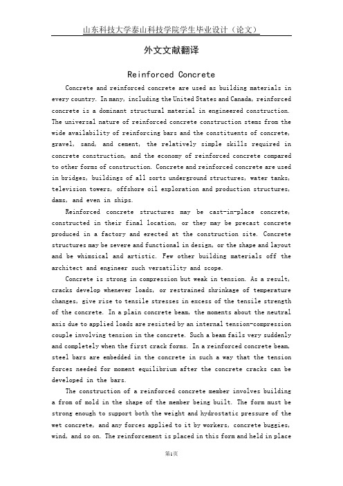
外文文献翻译Reinforced ConcreteConcrete and reinforced concrete are used as building materials in every country. In many, including the United States and Canada, reinforced concrete is a dominant structural material in engineered construction. The universal nature of reinforced concrete construction stems from the wide availability of reinforcing bars and the constituents of concrete, gravel, sand, and cement, the relatively simple skills required in concrete construction, and the economy of reinforced concrete compared to other forms of construction. Concrete and reinforced concrete are used in bridges, buildings of all sorts underground structures, water tanks, television towers, offshore oil exploration and production structures, dams, and even in ships.Reinforced concrete structures may be cast-in-place concrete, constructed in their final location, or they may be precast concrete produced in a factory and erected at the construction site. Concrete structures may be severe and functional in design, or the shape and layout and be whimsical and artistic. Few other building materials off the architect and engineer such versatility and scope.Concrete is strong in compression but weak in tension. As a result, cracks develop whenever loads, or restrained shrinkage of temperature changes, give rise to tensile stresses in excess of the tensile strength of the concrete. In a plain concrete beam, the moments about the neutral axis due to applied loads are resisted by an internal tension-compression couple involving tension in the concrete. Such a beam fails very suddenly and completely when the first crack forms. In a reinforced concrete beam, steel bars are embedded in the concrete in such a way that the tension forces needed for moment equilibrium after the concrete cracks can be developed in the bars.The construction of a reinforced concrete member involves building a from of mold in the shape of the member being built. The form must be strong enough to support both the weight and hydrostatic pressure of the wet concrete, and any forces applied to it by workers, concrete buggies, wind, and so on. The reinforcement is placed in this form and held in placeduring the concreting operation. After the concrete has hardened, the forms are removed. As the forms are removed, props of shores are installed to support the weight of the concrete until it has reached sufficient strength to support the loads by itself.The designer must proportion a concrete member for adequate strength to resist the loads and adequate stiffness to prevent excessive deflections. In beam must be proportioned so that it can be constructed. For example, the reinforcement must be detailed so that it can be assembled in the field, and since the concrete is placed in the form after the reinforcement is in place, the concrete must be able to flow around, between, and past the reinforcement to fill all parts of the form completely.The choice of whether a structure should be built of concrete, steel, masonry, or timber depends on the availability of materials and on a number of value decisions. The choice of structural system is made by the architect of engineer early in the design, based on the following considerations:1. Economy. Frequently, the foremost consideration is the overall const of the structure. This is, of course, a function of the costs of the materials and the labor necessary to erect them. Frequently, however, the overall cost is affected as much or more by the overall construction time since the contractor and owner must borrow or otherwise allocate money to carry out the construction and will not receive a return on this investment until the building is ready for occupancy. In a typical large apartment of commercial project, the cost of construction financing will be a significant fraction of the total cost. As a result, financial savings due to rapid construction may more than offset increased material costs. For this reason, any measures the designer can take to standardize the design and forming will generally pay off in reduced overall costs.In many cases the long-term economy of the structure may be more important than the first cost. As a result, maintenance and durability are important consideration.2. Suitability of material for architectural and structural function.A reinforced concrete system frequently allows the designer to combine the architectural and structural functions. Concrete has the advantage that it is placed in a plastic condition and is given the desired shapeand texture by means of the forms and the finishing techniques. This allows such elements ad flat plates or other types of slabs to serve as load-bearing elements while providing the finished floor and / or ceiling surfaces. Similarly, reinforced concrete walls can provide architecturally attractive surfaces in addition to having the ability to resist gravity, wind, or seismic loads. Finally, the choice of size of shape is governed by the designer and not by the availability of standard manufactured members.3. Fire resistance. The structure in a building must withstand the effects of a fire and remain standing while the building is evacuated and the fire is extinguished. A concrete building inherently has a 1- to 3-hour fire rating without special fireproofing or other details. Structural steel or timber buildings must be fireproofed to attain similar fire ratings.4. Low maintenance.Concrete members inherently require less maintenance than do structural steel or timber members. This is particularly true if dense, air-entrained concrete has been used for surfaces exposed to the atmosphere, and if care has been taken in the design to provide adequate drainage off and away from the structure. Special precautions must be taken for concrete exposed to salts such as deicing chemicals.5. Availability of materials. Sand, gravel, cement, and concrete mixing facilities are very widely available, and reinforcing steel can be transported to most job sites more easily than can structural steel. As a result, reinforced concrete is frequently used in remote areas.On the other hand, there are a number of factors that may cause one to select a material other than reinforced concrete. These include:1. Low tensile strength.The tensile strength concrete is much lower than its compressive strength ( about 1/10 ), and hence concrete is subject to cracking. In structural uses this is overcome by using reinforcement to carry tensile forces and limit crack widths to within acceptable values. Unless care is taken in design and construction, however, these cracks may be unsightly or may allow penetration of water. When this occurs, water or chemicals such as road deicing salts may cause deterioration or staining of the concrete. Special design details are required in such cases. In the case of water-retaining structures, special details and /of prestressing are required to prevent leakage.2. Forms and shoring. The construction of a cast-in-place structure involves three steps not encountered in the construction of steel or timber structures. These are ( a ) the construction of the forms, ( b ) the removal of these forms, and (c) propping or shoring the new concrete to support its weight until its strength is adequate. Each of these steps involves labor and / or materials, which are not necessary with other forms of construction.3. Relatively low strength per unit of weight for volume.The compressive strength of concrete is roughly 5 to 10% that of steel, while its unit density is roughly 30% that of steel. As a result, a concrete structure requires a larger volume and a greater weight of material than does a comparable steel structure. As a result, long-span structures are often built from steel.4. Time-dependent volume changes. Both concrete and steel undergo-approximately the same amount of thermal expansion and contraction. Because there is less mass of steel to be heated or cooled, and because steel is a better concrete, a steel structure is generally affected by temperature changes to a greater extent than is a concrete structure. On the other hand, concrete undergoes frying shrinkage, which, if restrained, may cause deflections or cracking. Furthermore, deflections will tend to increase with time, possibly doubling, due to creep of the concrete under sustained loads.In almost every branch of civil engineering and architecture extensive use is made of reinforced concrete for structures and foundations. Engineers and architects requires basic knowledge of reinforced concrete design throughout their professional careers. Much of this text is directly concerned with the behavior and proportioning of components that make up typical reinforced concrete structures-beams, columns, and slabs. Once the behavior of these individual elements is understood, the designer will have the background to analyze and design a wide range of complex structures, such as foundations, buildings, and bridges, composed of these elements.Since reinforced concrete is a no homogeneous material that creeps, shrinks, and cracks, its stresses cannot be accurately predicted by the traditional equations derived in a course in strength of materials forhomogeneous elastic materials. Much of reinforced concrete design in therefore empirical, i.e., design equations and design methods are based on experimental and time-proved results instead of being derived exclusively from theoretical formulations.A thorough understanding of the behavior of reinforced concrete will allow the designer to convert an otherwise brittle material into tough ductile structural elements and thereby take advantage of concrete’s desirable characteristics, its high compressive strength, its fire resistance, and its durability.Concrete, a stone like material, is made by mixing cement, water, fine aggregate ( often sand ), coarse aggregate, and frequently other additives ( that modify properties ) into a workable mixture. In its unhardened or plastic state, concrete can be placed in forms to produce a large variety of structural elements. Although the hardened concrete by itself, i.e., without any reinforcement, is strong in compression, it lacks tensile strength and therefore cracks easily. Because unreinforced concrete is brittle, it cannot undergo large deformations under load and fails suddenly-without warning. The addition fo steel reinforcement to the concrete reduces the negative effects of its two principal inherent weaknesses, its susceptibility to cracking and its brittleness. When the reinforcement is strongly bonded to the concrete, a strong, stiff, and ductile construction material is produced. This material, called reinforced concrete, is used extensively to construct foundations, structural frames, storage takes, shell roofs, highways, walls, dams, canals, and innumerable other structures and building products. Two other characteristics of concrete that are present even when concrete is reinforced are shrinkage and creep, but the negative effects of these properties can be mitigated by careful design.A code is a set technical specifications and standards that control important details of design and construction. The purpose of codes it produce structures so that the public will be protected from poor of inadequate and construction.Two types f coeds exist. One type, called a structural code, is originated and controlled by specialists who are concerned with the proper use of a specific material or who are involved with the safe design of a particular class of structures.The second type of code, called a building code, is established to cover construction in a given region, often a city or a state. The objective of a building code is also to protect the public by accounting for the influence of the local environmental conditions on construction. For example, local authorities may specify additional provisions to account for such regional conditions as earthquake, heavy snow, or tornados. National structural codes genrally are incorporated into local building codes.The American Concrete Institute ( ACI ) Building Code covering the design of reinforced concrete buildings. It contains provisions covering all aspects of reinforced concrete manufacture, design, and construction. It includes specifications on quality of materials, details on mixing and placing concrete, design assumptions for the analysis of continuous structures, and equations for proportioning members for design forces.All structures must be proportioned so they will not fail or deform excessively under any possible condition of service. Therefore it is important that an engineer use great care in anticipating all the probable loads to which a structure will be subjected during its lifetime.Although the design of most members is controlled typically by dead and live load acting simultaneously, consideration must also be given to the forces produced by wind, impact, shrinkage, temperature change, creep and support settlements, earthquake, and so forth.The load associated with the weight of the structure itself and its permanent components is called the dead load. The dead load of concrete members, which is substantial, should never be neglected in design computations. The exact magnitude of the dead load is not known accurately until members have been sized. Since some figure for the dead load must be used in computations to size the members, its magnitude must be estimated at first. After a structure has been analyzed, the members sized, and architectural details completed, the dead load can be computed more accurately. If the computed dead load is approximately equal to the initial estimate of its value ( or slightly less ), the design is complete, but if a significant difference exists between the computed and estimated values of dead weight, the computations should be revised using an improved value of dead load. An accurate estimate of dead load is particularly important when spans are long, say over 75 ft ( 22.9 m ),because dead load constitutes a major portion of the design load.Live loads associated with building use are specific items of equipment and occupants in a certain area of a building, building codes specify values of uniform live for which members are to be designed.After the structure has been sized for vertical load, it is checked for wind in combination with dead and live load as specified in the code. Wind loads do not usually control the size of members in building less than 16 to 18 stories, but for tall buildings wind loads become significant and cause large forces to develop in the structures. Under these conditions economy can be achieved only by selecting a structural system that is able to transfer horizontal loads into the ground efficiently.钢筋混凝土在每一个国家,混凝土及钢筋混凝土都被用来作为建筑材料。
土木工程(钢结构和钢筋混凝土结构)外文文献翻译

⼟⽊⼯程(钢结构和钢筋混凝⼟结构)外⽂⽂献翻译⽂献信息:⽂献标题:Recent research and design developments in steel and composite steel–concrete structures in USA(近期美国在钢结构和钢筋混凝⼟结构研究和设计⽅⾯的发展)国外作者:Theodore V.Galambos⽂献出处:《Journal of Constructional Steel Research》,2000, 55(1-3):289-303字数统计:英⽂4718单词,23395字符;中⽂7671汉字外⽂⽂献:Recent research and design developments in steel and composite steel–concrete structures in USA Abstract A brief review of the status of structural steel research in the US at the end of the Twentieth Century is presented in this paper to show that while many problems are being solved, there are new and challenging problems remaining. The chief impetus for continued research is that provided by natural disasters, such as earthquakes, tropical storms, tornadoes and floods occurring in densely populated urban areas. New materials and new experimental and computational technologies also give rise to new and exciting research problems.Keywords: Bridges; Buildings; Design; Research; Steel structures; United States of America; Seismic behavior; High-performance materials1. IntroductionThe purpose of this paper is to give a brief overview of the current developments in structural steel research in the US, and of the future directions that the structural steel engineering research may take in the coming Century. The drivingforces of research in this field are the following:new construction methods and construction productsnew materialseconomic considerationsnatural disastersThree of these motivations are common to all engineering developments, not just to structural engineering. However, the impetus due to natural disasters is unique to our field. Recent major natural disasters in the US, such as the Northridge earthquake in California and hurricane Andrew in Florida, have spurred much of the current research activity.The presentation here is of necessity incomplete, because the author is not aware of all research going on everywhere in the country and there is not enough space in this presentation. The overview is meant to give a general flavor of the research activities, and to show that a significant effort is going on in the US. The following is a list of 10 major topics in steel research: 1.Limit States Design for bridges2.Monitoring of structural performance in the field3.Design of seismically resistant connections4.Curved girder bridges/doc/c0cdca1fb8f67c1cfbd6b81b.html posite columns with high-performance concrete6.Building frames with semi-rigid joints7.“Advanced Structural Analysis” for buildings8.Repair and retrofit of structures9.Steel structures with high-performance steels10.Cold-formed steel structuresThe next parts of this paper will give brief discussions on some of these topics. Several topics will then be elaborated in more detail. The paper will conclude with a look toward the future of structural steel research.2.Research on steel bridgesThe American Association of State Transportation and Highway Officials (AASHTO) is the authority that promulgates design standards for bridges in the US. In 1994 it has issued a new design specification which is a Limit States Design standard that is based on the principles of reliability theory. A great deal of work went into the development of this code in the past decade, especially on calibration and on the probabilistic evaluation of the previous specification. The code is now being implemented in the design office, together with the introduction of the Systeme Internationale units. Many questions remain open about the new method of design, and there are many new projects that deal with the reliability studies of the bridge as a system. One such current project is a study to develop probabilistic models, load factors, and rational load-combination rules for the combined effects of liveload and wind; live-load and earthquake; live-load, wind and ship collision; and ship collision, wind, and scour. There are also many field measurements of bridge behavior, using modern tools of inspection and monitoring such as acoustic emission techniques and other means of non-destructive evaluation. Such fieldwork necessitates parallel studies in the laboratory, and the evolution of ever more sophisticated high-technology data transmission methods.America has an aging steel bridge population and many problems arise from fatigue and corrosion. Fatigue studies on full-scale components of the Williamsburg Bridge in New York have recently been completed at Lehigh University. A probabilistic AASHTO bridge evaluation regulation has been in effect since 1989, and it is employed to assess the future useful life of structures using rational methods that include field observation and measurement together with probabilistic analysis. Such an activity also fosters additional research because many issues are still unresolved. One such area is the study of the shakedown of shear connectors in composite bridges. This work has been recently completed at the University of Missouri.In addition to fatigue and corrosion, the major danger to bridges is the possibility of earthquake induced damage. This also has spawned many research projects on the repair and retrofit of steel superstructures and the supporting concrete piers. Many bridges in the country are being strengthened for earthquake resistance.One area that is receiving much research attention is the strengthening of concrete piers by “jacketing” them by sheets of high-performance reinforced plastic.The previously described research deals mainly with the behavior of existing structures and the design of new bridges. However, there is also a vigorous activity on novel bridge systems. This research is centered on the application of high-performance steels for the design of innovative plate and box-girder bridges, such as corrugated webs, combinations of open and closed shapes, and longer spans for truss bridges. It should be mentioned here that, in addition to work on steel bridges, there is also very active research going on in the study of the behavior of prestressed concrete girders made from very high strength concrete. The performance and design of smaller bridges using pultruded high-performance plastic composite members is also being studied extensively at present. New continuous bridge systems with steelconcrete composite segments in both the positive moment and the negative moment regions are being considered. Several researchers have developed strong capabilities to model the three-dimensional non-linear behavior of individual plate girders, and many studies are being performed on the buckling and post-buckling characteristics of such structures. Companion experimental studies are also made, especially on members built from high-performance steels. A full-scale bridge of such steel has been designed, and will soon be constructed and then tested under traffic loading. Research efforts are also underway on the study of the fatigue of large expansion joint elements and on the fatigue of highway sign structures.The final subject to be mentioned is the resurgence of studies of composite steelconcrete horizontally curved steel girder bridges. A just completed project at the University of Minnesota monitored the stresses and the deflections in a skewed and curved bridge during all phases of construction, starting from the fabrication yard to the completed bridge. Excellent correlation was found to exist between the measured stresses and deformations and the calculated values. The stresses and deflections during construction were found to be relatively small, that is, the construction process did not cause severe trauma to the system. The bridge has now been tested under service loading, using fully loaded gravel trucks, for two years, and it will continue tobe studied for further years to measure changes in performance under service over time. A major testing project is being conducted at the Federal Highway Administration laboratory in Washington, DC, where a half-scale curved composite girder bridge is currently being tested to determine its limit states. The test-bridge was designed to act as its own test-frame, where various portions can be replaced after testing. Multiple flexure tests, shear tests, and tests under combined bending and shear, are thus performed with realistic end-conditions and restraints. The experiments are also modeled by finite element analysis to check conformance between reality and prediction. Finally design standards will be evolved from the knowledge gained. This last project is the largest bridge research project in the USA at the present time.From the discussion above it can be seen that even though there is no large expansion of the nation’s highway and railr oadsystem, there is extensive work going on in bridge research. The major challenge facing both the researcher and the transportation engineer is the maintenance of a healthy but aging system, seeing to its gradual replacement while keeping it safe and serviceable.3.Research on steel members and framesThere are many research studies on the strength and behavior of steel building structures. The most important of these have to do with the behavior and design of steel structures under severe seismic events. This topic will be discussed later in this paper. The most significant trends of the non-seismic research are the following: ?“Advanced” methods of structural analysis and design are actively studied at many Universities, notably at Cornell, Purdue, Stanford, and Georgia Tech Universities. Such analysis methods are meant to determine the load-deformation behavior of frames up to and beyond failure, including inelastic behavior, force redistribution, plastic hinge formation, second-order effects and frame instability. When these methods are fully operational, the structure will not have to undergo a member check, because the finite element analysis of the frame automatically performs this job. In addition to the research on the best approaches to do this advanced analysis, there are also many studies on simplifications that can be easilyutilized in the design office while still maintaining the advantages of a more complex analysis. The advanced analysis method is well developed for in-plane behavior, but much work is yet to be done on the cases where bi-axial bending or lateraltorsional buckling must be considered. Some successes have been achieved, but the research is far from complete. Another aspect of the frame behavior work is the study of the frames with semirigid joints. The American Institute of Steel construction (AISC) has published design methods for office use. Current research is concentrating on the behavior of such structures under seismic loading. It appears that it is possible to use such frames in some seismic situations, that is, frames under about 8 to 10 stories in height under moderate earthquake loads. The future of structures with semi-rigid frames looks very promising, mainly because of the efforts of researchers such as Leon at Georgia Tech University , and many others. Research on member behavior is concerned with studying the buckling and postbuckling behavior of compact angle and wide-flange beam members by advanced commercial finite element programs. Such research is going back to examine the assumptions made in the 1950s and 1960s when the plastic design compactness and bracing requirements were first formulated on a semi-empirical basis. The non-linear finite element computations permit the “re-testing” of the old experiments a nd the performing of new computer experiments to study new types of members and new types of steels. White of Georgia Tech is one of the pioneers in this work. Some current research at the US military Academy and at the University of Minnesota by Earls is discussed later in this report. The significance of this type of research is that the phenomena of extreme yielding and distortion can be efficiently examined in parameter studies performed on the computer. The computer results can be verified with old experiments, or a small number of new experiments. These studies show a good prospect for new insights into old problems that heretofore were never fully solved.4.Research on cold-formed steel structuresNext to seismic work, the most active part of research in the US is on cold-formed steel structures. The reason for this is that the supporting industry is expanding, especially in the area of individual family dwellings. As the cost of wood goes up, steel framed houses become more and more economical. The intellectual problems of thin-walled structures buckling in multiple modes under very large deformations have attracted some of the best minds in stability research. As a consequence, many new problems have been solved: complex member stiffening systems, stability and bracing of C and Z beams, composite slabs, perforated columns, standing-seam roof systems, bracing and stability of beams with very complicated shapes, cold-formed members with steels of high yield stress-to-tensile strength ratio, and many other interesting applications. The American Iron and Steel Institute (AISI) has issued a new expanded standard in 1996 that brought many of these research results into the hands of the designer.5.Research on steel-concrete composite structuresAlmost all structural steel bridges and buildings in the US are built with composite beams or girders. In contrast, very few columns are built as composite members. The area of composite column research is very active presently to fill up the gap of technical information on the behavior of such members. The subject of steel tubes filled with high-strength concrete is especially active. One of the aims of research performed by Hajjar at the University of Minnesota is to develop a fundamental understanding of the various interacting phenomena that occur in concrete-filled columns and beam-columns under monotonic and cyclic load. The other aim is to obtain a basic understanding of the behavior of connections of wide-flange beams to concrete filled tubes.Other major research work concerns the behavior and design of built-up composite wide-flange bridge girders under both positive and negative bending. This work is performed by Frank at the University of Texas at Austin and by White of Georgia Tech, and it involves extensive studies of the buckling and post-buckling of thin stiffened webs. Already mentioned is the examination of the shakedown of composite bridges. The question to be answered is whether a composite bridgegirder loses composite action under repeated cycles of loads which are greater than the elastic limit load and less than the plastic mechanism load. A new study has been initiated at the University of Minnesota on the interaction between a semi-rigid steel frame system and a concrete shear wall connected by stud shear connectors.6.Research on connectionsConnection research continues to interest researchers because of the great variety of joint types. The majority of the connection work is currently related to the seismic problems that will be discussed in the next section of this paper. The most interest in non-seismic connections is the characterization of the monotonic moment-rotation behavior of various types of semi-rigid joints.7.Research on structures and connections subject to seismic forcesThe most compelling driving force for the present structural steel research effort in the US was the January 17, 1994 earthquake in Northridge, California, North of Los Angeles. The major problem for steel structures was the extensive failure of prequalified welded rigid joints by brittle fracture. In over 150 buildings of one to 26 stories high there were over a thousand fractured joints. The buildings did not collapse, nor did they show any external signs of distress, and there were no human injuries or deaths. A typical joint is shown in Fig. 1.In this connection the flanges of the beams are welded to the flanges of the column by full-penetration butt welds. The webs are bolted to the beams and welded to the columns. The characteristic features of this type of connection are the backing bars at the bottom of the beam flange, and the cope-holes left open to facilitate the field welding of the beam flanges. Fractures occurred in the welds, in the beam flanges, and/or in the column flanges, sometimes penetrating into the webs.Once the problem was discovered several large research projects were initiated at various university laboratories, such as The University of California at San Diego, the University of Washington in Seattle, the University of Texas at Austin, Lehigh University at Bethlehem, Pennsylvania, and at other places. The US Government under the leadership of the Federal Emergency Management Agency (FEMA) instituted a major national research effort. The needed work was deemed so extensive that no single research agency could hope to cope with it. Consequently three California groups formed a consortium which manages the work:1.Structural Engineering Association of California2.Applied Technology Council3.California Universities for Research in Earthquake EngineeringThe first letters in the name of each agency were combined to form the acronym SAC, which is the name of the joint venture that manages the research. We shall read much from this agency as the results of the massive amounts of research performed under its aegis are being published in the next few years.The goals of the program are to develop reliable, practical and cost-effective guidelines for the identification and inspection of at-risk steel moment frame buildings, the repair or upgrading of damaged buildings, the design of new construction, and the rehabilitation of undamaged buildings. As can be seen, the scope far exceeds the narrow look at the connections only.The first phase of the research was completed at the end of 1996, and its main aim was to arrive at interim guidelines so that design work could proceed. It consisted of the following components:A state-of-the-art assessment of knowledge on steel connectionsA survey of building damageThe evaluation of ground motionDetailed building analyses and case studiesA preliminary experimental programProfessional training and quality assurance programsPublishing of the Interim Design GuidelinesA number of reports were issued in this first phase of the work. A partial list of these is appended at the end of this paper.During the first phase of the SAC project a series of full-scale connection tests under static and, occasionally, dynamic cyclic tests were performed. Tests were of pre-Northridge-type connections (that is, connections as they existed at the time of the earthquake), of repaired and upgraded details, and of new recommended connection details. A schematic view of the testing program is illustrated in Fig. 2. Some recommended strategies for new design are schematically shown in Fig. 3.The following possible causes, and their combinations, were found to have contributed to the connection failures: Inadequate workmanship in the field weldsInsufficient notch-toughness of the weld metalStress raisers caused by t he backing barsLack of complete fusion near the backing barWeld bead sizes were too bigSlag inclusion in the weldsWhile many of the failures can be directly attributed to the welding and the material of the joints, there are more serious questions relative to the structural system that had evolved over the years mainly based on economic considerations. The structural system used relatively few rigid-frames of heavy members that were designed to absorb the seismic forces for large parts of the structure. These few lateral-force resistant frames provide insufficient redundancy. More rigid-frames with smaller members could have provided a tougher and more ductile structural system. There is a question of size effect: test results from joints of smaller members were extrapolated to joints with larger members without adequate test verification. The effect of a large initial pulse may have triggered dynamic forces that could have caused brittle fracture in joints with fracture critical details and materials. Furthermore, the yield stress of the beams was about 30 to 40% larger than the minimum specified values assumed in design, and so the connection failed before the beams, which were supposed to form plastic hinges.As can be seen, there are many possible reasons for this massive failure rate, and there is blame to go around for everyone. No doubt, the discussion about why and how the joints failed will go on for many more years. The structural system just did not measure up to demands that were more severe than expected. What should be kept in mind, however, is that no structure collapsed or caused even superficial nonstructural damage, and no person was injured or killed. In the strictest sense the structure sacrificed itself so that no physical harm was done to its users. The economic harm, of course, was enormous. Phase 2 of the SAC project started on Jan. 1, 1996 and is planned to be completed on Dec. 31, 1999. Its aims are to provide advice and guidance to code officials, designers, steel makers, welding engineers, and fabricators, in fact, to anyone connected with earthquake resistant design of steel buildings. The work includes the development of design-criteria for new buildings, and inspection, evaluation, repair and retrofit procedures for existing buildings that are at risk. A broad scope of professional issues is being examined. Ultimately, a performance-based methodology will be recommended to the professions dealing with seismic design problems. All types of moment-frame connections will be studied: bolted and welded connections, semi-rigid connections, connections made with special steels, energy-dissipating connections, etc. The research consists of many new experiments on joints, as well as a systems-reliability-based probabilistic method for optimizing the best structural design and evaluation procedures.The research work of the Phase 2 SAC Project is essentially complete as of the date of this conference (Sep. 1999). The basic analytical and experimental work consists of the following topics:Materials and fracture issuesWelding, joining and inspectionAnalysis and testing of connectionsEarthquake performance of structural systemsSimulation of seismic responseData and concepts from these five teams have been absorbed and utilized by theteam working on the development of the reliability framework for performance prediction and evaluation. A number of extensive State-Of-The-Art (SOA) reports based on the research are now in the final stages of completion. The material from these SOA reports, as well as results from trial designs, cost analyses, loss analyses, and from an evaluation of social, economic and policy issues, will then be the basis of new seismic design criteria for use by building codes.Phase 2 of the SAC Project is by far the largest and most expensive cooperative structural engineering effort in the history of US structural steel research. Much is expected to come of it. The way steel structures will be designed for steel structures is going to be deeply affected. The Northridge earthquake of January 17, 1994 proved a warning and a lesson, as well as a major impetus to learn more and to apply this knowledge more effectively.8.Research on the required properties of high-performance steelsOne other example will be elaborated on a research topic that is not motivated by natural disaster but by technological development, as an illustration among many which could have been presented. Steel makers have recently developed the capability to produce so-called “high-performance” stee ls economically, and there is a desire to use these steels in civil and military construction. Such steels are of high strength, with yield points of around 500 to 700 MPa, they can be produced to a variety of weldability, corrosion and toughness characteristics. Much work has been done on these steels in Japan with theirapplication in seismic structures in mind. Structures from a steel, HSLA80, have been extensively studied at Lehigh University in the US . The research question to be answered is not “Give n a steel of certain properties, what are the member and structural characteristics?” but “Given the desired structural characteristics, what should the properties of the steel be?”. These questions were discussed in a workshop sponsored by the US National Institute of Standards in Technology (NIST) at the University of Minnesota on July 1, 1996. The purpose of this meeting was to define the research needs to adapt the high-performance steels to the requirements of the structural design standards. Many issues were raised, but hereonly the subject of compactness and lateral bracing will be briefly touched. The shape of the stress–strain curve has a profound effect on the inelastic load-deformation behavior of members, as illustrated by the following example. The idealized form of a tensile stress–strain diagram is shown in Fig. 4. Data for four representative steels are given in Table 1. Steel A is a new steel in Japan that has very good ductility and a low yield stress-to-tensile strength ratio (yield ratio), that is, it has about the same capacity to strainharden at structural carbon steel (Steel C; Steel B is a quenched and tempered steel with a very high yield stress but a high yield ratio; Steel D is the steel HSLA80 from the research at Lehigh).The load-deflection curves in Fig. 5 were obtained from a finite element analysis using the commercial program ABAQUS. The structure was a simply supported beam under a three-point loading. Lateral bracing was provided at the end-supports and under the central load-point. The section was a W200×46 (W8×31 in US units) profile, with a flange slenderness ratio b f/t f=7.8, a web slenderness ratioof h/t w=29.9 and an unbraced length slenderness of L b/r y=71. As seen from Fig. 5, the shape of the stress–strain curve can have a tremendous difference on the inelastic rotation capacity of a structural member. The most important parameter appears to be the yield ratio and the ductility of the steel.In addition to research on the high-performance steels, new work on the definition and improvement of conventional steels is also being conducted, spurred by the realization that the physical properties of steels as they are presently being produced are quite different from the steels for which the plastic design research was done 30 years ago. The yield stress is higher and it seems that due to the rotary straightening process the larger shapes end up with zones in their cross section where the ductility is unacceptably low.Further work on this subject is being pursued by Earls at the US Military Academy and by Ricles and his co-workers at Lehigh University. More finite element analyses and laboratory experiments are being conducted to establish the desired stress–strain characteristics of high-performance steel to achieve optimal dimensions for compactness limits, so that this material can be effectively used in seismic design applications. Additional work is done on the design of the best shapes for bridgegirders, and a full-scale girder bridge will be fabricated and tested at the structural laboratory of the Federal Highway Administration at Washington, DC.9.Future directions of structural steel research and conclusionThe future holds many challenges for structural steel research. The ongoing work necessitated by the two recent earthquakes that most affected conventional design methods, namely, the Northridge earthquake in the US and the Kobe earthquake in Japan, will continue well into the first decade of the next Century. It is very likely that future disasters of this type will bring yet other problems to the steel research community. There is a profound change in the philosophy of design for disasters: we can no longer be content with saving lives only, but we must also design structures which will not be so damaged as to require extensive repairs.Another major challenge will be the emergence of many new materials such as high-performance concrete and plastic composite structures. Steel structures will continually have to face the problem of having to demonstrate viability in the marketplace. This can only be accomplished by more innovative research. Furthermore, the new comprehensive limit-states design codes which are being implemented worldwide, need research to back up the assumptions used in the theories.Specifically, the following list highlights some of the needed research in steel structures:Systems reliability tools have been developed to a high degree of sophistication. These tools should be applied to the studies of bridge and building structures to define the optimal locations of monitoring instruments, to assess the。
- 1、下载文档前请自行甄别文档内容的完整性,平台不提供额外的编辑、内容补充、找答案等附加服务。
- 2、"仅部分预览"的文档,不可在线预览部分如存在完整性等问题,可反馈申请退款(可完整预览的文档不适用该条件!)。
- 3、如文档侵犯您的权益,请联系客服反馈,我们会尽快为您处理(人工客服工作时间:9:00-18:30)。
第五部分英文论文翻译Talling building and Steel constructionAlthough there have been many advancements in building construction technology in general. Spectacular archievements have been made in the design and construction of ultrahigh-rise buildings.The early development of high-rise buildings began with structural steel framing.Reinforced concrete and stressed-skin tube systems have since been economically and competitively used in a number of structures for both residential and commercial purposes.The high-rise buildings ranging from 50 to 110 stories that are being built all over the United States are the result of innovations and development of new structual systems.Greater height entails increased column and beam sizes to make buildings more rigid so that under wind load they will not sway beyond an acceptable limit.Excessive lateral sway may cause serious recurring damage to partitions,ceilings.and other architectural details. In addition,excessive sway may cause discomfort to the occupants of the building because their perception of such motion.Structural systems of reinforced concrete,as well as steel,take full advantage of inherent potential stiffness of the total building and therefore require additional stiffening to limit the sway.In a steel structure,forexample,the economy can be defined in terms of the total average quantity of steel per square foot of floor area of the building.Curve A in Fig .1 represents the average unit weight of a conventional frame with increasing numbers of stories. Curve B represents the average steel weight if the frame is protected from all lateral loads. The gap between the upper boundary and the lower boundary represents the premium for height for the traditional column-and-beam frame.Structural engineers have developed structural systems with a view to eliminating this premium.Systems in steel. Tall buildings in steel developed as a result of several types of structural innovations. The innovations have been applied to the construction of both office and apartment buildings.Frame with rigid belt trusses. In order to tie the exterior columns of a frame structure to the interior vertical trusses,a system of rigid belt trusses at mid-height and at the top of the building may be used. A good example of this system is the First Wisconsin Bank Building(1974) in Milwaukee.Framed tube. The maximum efficiency of the total structure of a tall building, for both strength and stiffness,to resist wind load can be achieved only if all column element can be connected to each other in such a way that the entire building acts as a hollow tube or rigid box in projecting out of the ground. This particular structural system was probably used for the first time in the 43-story reinforced concreteDeWitt Chestnut Apartment Building in Chicago. The most significant use of this system is in the twin structural steel towers of the 110-story World Trade Center building in New YorkColumn-diagonal truss tube. The exterior columns of a building can be spaced reasonably far apart and yet be made to work together as a tube by connecting them with diagonal members interesting at the centre line of the columns and beams. This simple yet extremely efficient system was used for the first time on the John Hancock Centre in Chicago, using as much steel as is normally needed for a traditional 40-story building.Bundled tube. With the continuing need for larger and taller buildings, the framed tube or the column-diagonal truss tube may be used in a bundled form to create larger tube envelopes while maintaining high efficiency. The 110-story Sears Roebuck Headquarters Building in Chicago has nine tube, bundled at the base of the building in three rows. Some of these individual tubes terminate at different heights of the building, demonstrating the unlimited architectural possibilities of this latest structural concept. The Sears tower, at a height of 1450 ft(442m), is the world’s tallest building.Stressed-skin tube system. The tube structural system was developed for improving the resistance to lateral forces (wind and earthquake) and the control of drift (lateral building movement ) in high-rise building. The stressed-skin tube takes the tube system a step further. The development of the stressed-skin tube utilizes the fa?ade of the building as a structural element which acts with the framed tube, thus providing an efficient way of resisting lateral loads in high-rise buildings, and resulting in cost-effective column-free interior space with a high ratio of net to gross floor area.Because of the contribution of the stressed-skin fa?ade, the framed members of the tube require less mass, and are thus lighter and less expensive. All the typical columns and spandrel beams are standard rolled shapes,minimizing the use and cost of special built-up members. The depth requirement for the perimeter spandrel beams is also reduced, and the need for upset beams above floors, which would encroach on valuable space, is minimized. The structural system has been used on the 54-story One Mellon Bank Center in Pittburgh.Systems in concrete.While tall buildings constructed of steel had an early start, development of tall buildings of reinforced concrete progressed at a fast enough rate to provide a competitive chanllenge to structural steel systems for both office and apartment buildings.Framed tube. As discussed above, the first framed tube concept for tall buildings was used for the 43-story DeWitt Chestnut Apartment Building. In this building ,exterior columns were spaced at 5.5ft (1.68m) centers, and interior columns were used as needed to support the 8-in . -thick (20-m) flat-plate concrete slabs.Tube in tube. Another system in reinforced concrete for office buildings combines the traditional shear wall construction with an exterior framed tube. The system consists of an outer framed tube of very closely spaced columns and aninterior rigid shear wall tube enclosing the central service area. The system (Fig .2), known as the tube-in-tube system , made it possible to design the world’s present tallest (714ft or 218m)lightweight concrete building ( the 52-story One Shell Plaza Building in Houston) for the unit price of a traditional shear wall structure of only 35 stories.Systems combining both concrete and steel have also been developed, an examle of which is the composite system developed by skidmore, Owings &Merril in which an exterior closely spaced framed tube in concrete envelops an interior steel framing, thereby combining the advantages of both reinforced concrete and structural steel systems. The 52-story One Shell Square Building in New Orleans is based on this system.Steel construction refers to a broad range of building construction in which steel plays the leading role. Most steel construction consists of large-scale buildings or engineering works, with the steel generally in the form of beams, girders, bars, plates, and other members shaped through the hot-rolled process. Despite the increased use of other materials, steel construction remained a major outlet for the steel industries of the U.S, U.K, U.S.S.R, Japan, West German, France, and other steel producers in the 1970s.Early history. The history of steel construction begins paradoxically several decades before the introduction of the Bessemer and the Siemens-Martin (openj-hearth) processes made it possible to produce steel in quantities sufficient for structure use. Many of problems of steel construction were studied earlier in connection with iron construction, which began with the Coalbrookdale Bridge, built in cast iron over the Severn River in England in 1777. This and subsequent iron bridge work, in addition to the construction of steam boilers and iron ship hulls , spurred the development of techniques for fabricating, designing, and jioning. The advantages of iron over masonry lay in the much smaller amounts of material required. The truss form, based on the resistance of the triangle to deformation, long used in timber, was translated effectively into iron, with cast iron being used for compression members-i.e, those bearing the weight of direct loading-and wrought iron being used for tension members-i.e, those bearing the pull of suspended loading.The technique for passing iron, heated to the plastic state, between rolls to form flat and rounded bars, was developed as early as 1800;by 1819 angle irons were rolled; and in 1849 the first I beams, 17.7 feet (5.4m) long , were fabricated as roof girders for a Paris railroad station.Two years later Joseph Paxton of England built the Crystal Palace for the London Exposition of 1851. He is said to have conceived the idea of cage construction-using relatively slender iron beams as a skeleton for the glass walls of a large, open structure. Resistance to wind forces in the Crystal palace was provided by diagonal iron rods. Two feature are particularly important in the history of metal construction; first, the use of latticed girder, which are small trusses, a form first developed in timber bridges and other structures and translated into metal by Paxton ; and second, the joining of wrought-iron tension members and cast-ironcompression members by means of rivets inserted while hot.In 1853 the first metal floor beams were rolled for the Cooper Union Building in New York. In the light of the principal market demand for iron beams at the time, it is not surprising that the Cooper Union beams closely resembled railroad rails.The development of the Bessemer and Siemens-Martin processes in the 1850s and 1860s suddenly open the way to the use of steel for structural purpose. Stronger than iron in both tension and compression ,the newly available metal was seized on by imaginative engineers, notably by those involved in building the great number of heavy railroad bridges then in demand in Britain, Europe, and the U.S.A notable example was the Eads Bridge, also known as the St. Louis Bridge, in St. Louis (1867-1874), in which tubular steel ribs were used to form arches with a span of more than 500ft (152.5m). In Britain, the Firth of Forth cantilever bridge (1883-90) employed tubular struts, some 12 ft (3.66m) in diameter and 350 ft (107m) long. Such bridges and other structures were important in leading to the development and enforcement of standards and codification of permissible design stresses. The lack of adequate theoretical knowledge, and even of an adequate basis for theoretical studies, limited the value of stress analysis during the early years of the 20th century,asiccasionallyfailures,such as that of a cantilever bridge in Quebec in 1907,revealed.But failures were rare in the metal-skeleton office buildings;the simplicity of their design proved highly practical even in the absence of sophisticated analysis techniques. Throughout the first third of the century, ordinary carbon steel, without any special alloy strengthening or hardening, was universally used.The possibilities inherent in metal construction for high-rise building was demonstrated to the world by the Paris Exposition of 1889.for which Alexandre-Gustave Eiffel, a leading French bridge engineer, erected an openwork metal tower 300m (984 ft) high. Not only was the height-more than double that of the Great Pyramid-remarkable, but the speed of erection and low cost were even more so, a small crew completed the work in a few months.The first skyscrapers. Meantime, in the United States another important development was taking place. In 1884-85 Maj. William Le Baron Jenney, a Chicago engineer , had designed the Home Insurance Building, ten stories high, with a metal skeleton. Jenney’s beams were of Bessemer steel, though his columns were cast iron. Cast iron lintels supporting masonry over window openings were, in turn, supported on the cast iron columns. Soild masonry court and party walls provided lateral support against wind loading. Within a decade the same type of construction had been used in more than 30 office buildings in Chicago and New York. Steel played a larger and larger role in these , with riveted connections for beams and columns, sometimes strengthened for wind bracing by overlaying gusset plates at the junction of vertical and horizontal members. Light masonry curtain walls, supported at each floor level, replaced the old heavy masonry curtain walls, supported at each floor level , replaced the old heavy masonry.Though the new construction form was to remain centred almost entirely in America for several decade, its impact on the steel industry was worldwide. By thelast years of the 19th century, the basic structural shapes-I beams up to 20 in. ( 0.508m) in depth and Z and T shapes of lesser proportions were readily available, to combine with plates of several widths and thicknesses to make efficient members of any required size and strength. In 1885 the heaviest structural shape produced through hot-rolling weighed less than 100 pounds (45 kilograms) per foot; decade by decade this figure rose until in the 1960s it exceeded 700 pounds (320 kilograms) per foot.Coincident with the introduction of structural steel came the introduction of the Otis electric elevator in 1889. The demonstration of a safe passenger elevator, together with that of a safe and economical steel construction method, sent building heights soaring. In New York the 286-ft (87.2-m) Flatiron Building of 1902 was surpassed in 1904 by the 375-ft (115-m) Times Building ( renamed the Allied Chemical Building) , the 468-ft (143-m) City Investing Company Building in Wall Street, the 612-ft (187-m) Singer Building (1908), the 700-ft (214-m) Metropolitan Tower (1909) and, in 1913, the 780-ft (232-m) Woolworth Building.The rapid increase in height and the height-to-width ratio brought problems. To limit street congestion, building setback design was prescribed. On the technical side, the problem of lateral support was studied. A diagonal bracing system, such as that used in the Eiffel Tower, was not architecturally desirable in offices relying on sunlight for illumination. The answer was found in greater reliance on the bending resistance of certain individual beams and columns strategically designed into the skeletn frame, together with a high degree of rigidity sought at the junction of the beams and columns. With today’s modern interior lighting systems, however, diagonal bracing against wind loads has returned; one notable example is the John Hancock Center in Chicago, where the external X-braces form a dramatic part of the structure’s fa?ade.World War I brought an interruption to the boom in what had come to be called skyscrapers (the origin of the word is uncertain), but in the 1920s New York saw a resumption of the height race, culminating in the Empire State Building in the 1931. The Empire State’s 102 stories (1,250ft. [381m]) were to keep it established as the hightest building in the world for the next 40 years. Its speed of the erection demonstrated how thoroughly the new construction technique had been mastered. A depot across the bay at Bayonne, N.J., supplied the girders by lighter and truck on a schedule operated with millitary precision; nine derricks powerde by electric hoists lifted the girders to position; an industrial-railway setup moved steel and other material on each floor. Initial connections were made by bolting , closely followed by riveting, followed by masonry and finishing. The entire job was completed in one year and 45 days.The worldwide depression of the 1930s and World War II provided another interruption to steel construction development, but at the same time the introduction of welding to replace riveting provided an important advance.Joining of steel parts by metal are welding had been successfully achieved by the end of the 19th century and was used in emergency ship repairs during World War I, but its application to construction was limited until after World War II.Another advance in the same area had been the introduction of high-strength bolts toreplace rivets in field connections.Since the close of World War II, research in Europe, the U.S., and Japan has greatly extended knowledge of the behavior of different types of structural steelunder varying stresses, including those exceeding the yield point, making possiblemore refined and systematic analysis. This in turn has led to the adoption of moreliberal design codes in most countries, more imaginative design made possible byso-called plastic design ?The introduction of the computer by short-cutting tediouspaperwork, made further advances and savings possible.高层结构与钢结构近年来,尽管一般的建筑结构设计取得了很大的进步,但是取得显著成绩的还要属超高层建筑结构设计。