FTT131分布式高频录波仪
Philips Semiconductors BT131 series 数据手册

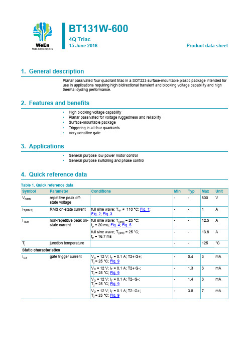
Philips SemiconductorsProduct specificationTriacs BT131 serieslogic levelGENERAL DESCRIPTIONQUICK REFERENCE DATAPassivated,sensitive gate triacs in a SYMBOL PARAMETERMAX.MAX.MAX.UNIT plastic envelope,intended for use in general purpose bidirectional BT131-500600800switching and phase control V DRM Repetitive peak off-state applications.These devices are voltages500600800V intended to be interfaced directly to I T(RMS)RMS on-state current111A microcontrollers,logic integrated I TSMNon-repetitive peak on-state circuits and other low power gate current161616Atrigger circuits.PINNING - TO92PIN CONFIGURATIONSYMBOLLIMITING VALUESLimiting values in accordance with the Absolute Maximum System (IEC 134).SYMBOL PARAMETERCONDITIONSMIN.MAX.UNIT -500-600-800V DRM Repetitive peak off-state -50016001800V voltagesI T(RMS)RMS on-state current full sine wave; T lead ≤51 ˚C-1A I TSMNon-repetitive peak full sine wave; T j = 25 ˚C prior to on-state current surge t = 20 ms -16A t = 16.7 ms -17.6A I 2t I 2t for fusingt = 10 ms- 1.28A 2s dI T /dtRepetitive rate of rise of I TM = 1.5 A; I G = 0.2 A;on-state current after dI G /dt = 0.2 A/µstriggeringT2+ G+-50A/µs T2+ G--50A/µs T2- G--50A/µs T2- G+-10A/µs I GM Peak gate current -2A V GM Peak gate voltage -5V P GM Peak gate power -5W P G(AV)Average gate power over any 20 ms period-0.5W T stg Storage temperature -40150˚C T jOperating junction -125˚Ctemperature1 Although not recommended, off-state voltages up to 800V may be applied without damage, but the triac may switch to the on-state. The rate of rise of current should not exceed 3 A/µs.查询BT131 series供应商THERMAL RESISTANCESSYMBOL PARAMETER CONDITIONS MIN.TYP.MAX.UNITRth j-lead Thermal resistance full cycle--60K/W junction to lead half cycle--80K/WRth j-a Thermal resistance pcb mounted;lead length = 4mm-150-K/W junction to ambientSTATIC CHARACTERISTICSTj= 25 ˚C unless otherwise statedSYMBOL PARAMETER CONDITIONS MIN.TYP.MAX.UNITI GT Gate trigger current VD= 12 V; IT= 0.1 AT2+ G+-0.43mAT2+ G-- 1.33mAT2- G-- 1.43mAT2- G+- 3.87mAI L Latching current VD= 12 V; IGT= 0.1 AT2+ G+- 1.25mAT2+ G-- 4.08mAT2- G-- 1.05mAT2- G+- 2.58mAI H Holding current VD= 12 V; IGT= 0.1 A- 1.35mAVT On-state voltage IT= 2.0 A- 1.2 1.5VVGT Gate trigger voltage VD= 12 V; IT= 0.1 A-0.7 1.5VVD= 400 V; IT= 0.1 A; Tj= 125 ˚C0.20.3-VI D Off-state leakage current VD= VDRM(max); Tj= 125 ˚C-0.10.5mADYNAMIC CHARACTERISTICSTj= 25 ˚C unless otherwise statedSYMBOL PARAMETER CONDITIONS MIN.TYP.MAX.UNITdVD /dt Critical rate of rise of VDM= 67% VDRM(max); Tj= 125 ˚C;515-V/µs off-state voltage exponential waveform; RGK= 1 kΩt gt Gate controlled turn-on ITM= 1.5 A; VD= VDRM(max); IG= 0.1 A;-2-µs time dIG/dt = 5 A/µsFig.9. Normalised holding current I H (T j )/ I H (25˚C),versus junction temperature T j .Fig.12. Typical, critical rate of rise of off-state voltage,dV D /dt versus junction temperature T j .-505010015000.511.522.53Tj / CIH(Tj)IH(25C)0501001501101001000Tj / CdVD/dt (V/us)MECHANICAL DATA1. Epoxy meets UL94 V0 at 1/8".DEFINITIONSData sheet statusObjective specification This data sheet contains target or goal specifications for product development. Preliminary specification This data sheet contains preliminary data; supplementary data may be published later. Product specification This data sheet contains final product specifications.Limiting valuesLimiting values are given in accordance with the Absolute Maximum Rating System (IEC 134). Stress above one or more of the limiting values may cause permanent damage to the device. These are stress ratings only and operation of the device at these or at any other conditions above those given in the Characteristics sections of this specification is not implied. Exposure to limiting values for extended periods may affect device reliability. Application informationWhere application information is given, it is advisory and does not form part of the specification.Philips Electronics N.V. 2000All rights are reserved. Reproduction in whole or in part is prohibited without the prior written consent of the copyright owner.The information presented in this document does not form part of any quotation or contract, it is believed to be accurate and reliable and may be changed without notice. No liability will be accepted by the publisher for any consequence of its use. Publication thereof does not convey nor imply any license under patent or other industrial or intellectual property rights.LIFE SUPPORT APPLICATIONSThese products are not designed for use in life support appliances, devices or systems where malfunction of these products can be reasonably expected to result in personal injury. Philips customers using or selling these products for use in such applications do so at their own risk and agree to fully indemnify Philips for any damages resulting from such improper use or sale.。
FTR-01中文说明书2008-10-27故障录波

FTR-01 电力系统故障录波及分析装置用户手册FTR-01H 便携式电力系统故障录波及分析装置用户手册武汉方得电子有限公司Wuhan Fount Electronics Co., Ltd.Document Number WH40-9101-03 Version 2008-10-27FTR-01电力系统故障录波及分析装置用户手册FTR-01H便携式电力系统故障录波及分析装置用户手册本手册内容如有更改,恕不通告。
没有武汉方得电子有限公司的书面许可,本手册任何部分都不许以任何(电子的或机械的)形式、方法或以任何目的而进行传播。
是武汉方得电子有限公司的商标ReplayB 是武汉方得电子有限公司的商标Windows 是微软公司的商标所有其他公司的商标和知识产权在本手册中都予以认可©2008武汉方得电子有限公司版权所有中华人民共和国湖北省武汉市东湖开发区关山二路特1号国际企业中心栖凤楼B座4层电话 +86 027 8266 8396传真 +86 027 6784 8757邮政编码 430074E-mail: whft@Information of modifying2007-07-03 2007-07-04 2007-07-05 2007-07-09 2007-07-10 2007-07-12 2007-07-13 2007-07-18 2007-07-20 2007-11-02 2008-07-21 2008-09-22 2008-10-27FTR-01型电力系统故障录波及分析装置用户手册I目录第一章FTR-01的系统功能及技术指标.......................................................................................... 11.1装臵概述.......................................................................................................................................... 11.1.1用途............................................................................................................................................. 11.1.2FTR-01结构体系 .................................................................................................................... 11.1.3输入信号.................................................................................................................................... 11.2系统新特性 ..................................................................................................................................... 11.2.1软件与硬件 ............................................................................................................................... 11.2.2高抗干扰性 ............................................................................................................................... 21.2.3专用DSP ................................................................................................................................... 21.2.4高速的PCI总线 ..................................................................................................................... 21.2.5工频信号自动频率跟踪 ........................................................................................................ 21.2.6采集单元远距离分布式安装 ............................................................................................... 21.3主要技术指标................................................................................................................................. 21.4设备的选配................................................................................................................................... 41.4.1设备型号的定义...................................................................................................................... 41.4.2开关量扩展 ............................................................................................................................... 41.4.3可供选用的型号...................................................................................................................... 4第二章FTR-01的被测输入量的接入 .............................................................................................. 52.1交流电压量的接入 ..................................................................................................................... 52.2交流电流量的接入 ..................................................................................................................... 52.3开关量的接入 .............................................................................................................................. 62.4数据采集单元(RAU)量程的硬件调整.................................................................................. 7第三章FTR-01的面板功能 ................................................................................................................ 83.1FTR-01前面板............................................................................................................................... 83.2面板功能.......................................................................................................................................... 83.2.1状态指示灯 ............................................................................................................................... 83.2.2液晶屏功能指示...................................................................................................................... 83.3功能菜单.......................................................................................................................................... 93.4功能菜单的使用 ........................................................................................................................ 103.4.1通道监控................................................................................................................................ 103.4.2记录列表................................................................................................................................ 103.4.3打印机配臵 ........................................................................................................................... 113.5FTR-01后面板与功能 ............................................................................................................. 123.5.1FTR-01后面板布臵............................................................................................................ 123.5.2FTR-01后面板结构与功能 .............................................................................................. 123.6RAU后面板与功能.................................................................................................................. 133.6.1RAU后面板 .......................................................................................................................... 133.6.2RAU后面板布臵与功能 ................................................................................................... 13第四章软件“FTR录波器管理系统”....................................................................................... 14IIFTR-01型电力系统故障录波及分析装置用户手册什么是“FTR录波器管理系统”........................................................................................ 144.2“FTR录波器管理系统”运行环境...................................................................................... 144.3FTR-01与后台的连接 ............................................................................................................. 144.3.1网络物理连接....................................................................................................................... 144.3.2网络连通的试验.................................................................................................................. 144.4使用M ODEM进行远方传送................................................................................................... 154.5安装和运行软件“FTR录波器管理系统”...................................................................... 164.6FTR录波器管理系统(R EPLAY B)件................................................................................ 174.7FTR录波器管理系统(R EPLAY B)对FTR-01设备群的管理.................................... 184.7.1在软件ReplayB中添加子站名称及设备名称............................................................ 184.7.2获取FTR-01的前台配臵.................................................................................................. 19第五章FTR-01输入通道属性的描述与起动的整定............................................................... 205.1模拟通道属性的描述............................................................................................................... 205.2模拟通道起动录波的设臵...................................................................................................... 215.3开关量输入通道属性的设臵 ................................................................................................. 225.4记录格式的设定 ........................................................................................................................ 235.4.1瞬态故障DFR(Disturbance Fault Recording)记录格式的设臵 ....................... 235.4.2连续稳态记录CSS(Continuous Steady State recording)记录格式的设臵 ...... 24第六章FTR-01的校准 ..................................................................................................................... 256.1校准信号源设备的准备 .......................................................................................................... 256.2确定硬件量程和通道配臵...................................................................................................... 256.3FTR录波器校准软件R EPLAY C AL 的使用 ......................................................................... 25第七章FTR-01故障记录的读取 ................................................................................................... 287.1在R EPLAY B中选定目标设备................................................................................................ 287.2设臵数据抽取策略.................................................................................................................... 297.3瞬态故障记录文件DFR(D ISTURBANCE F AULT R ECORDING)的提取 ...................... 297.4连续式稳态记录CSS(C ONTINUOUS S TEADY S TATE RECORDING)文件的提取...... 307.5触发式稳态记录TSS(T RIGGERED S TEADY S TATE RECORDING)文件的读取 ......... 317.6故障记录文件的断点续传...................................................................................................... 32第八章使用软件CMDVIEW观察分析故障记录................................................................... 348.1打开故障记录............................................................................................................................. 348.2C MD V IEW工具栏图标的功能................................................................................................ 358.3选择显示通道............................................................................................................................. 368.4通道交换显示位臵.................................................................................................................... 368.5改变波形和背景的颜色 .......................................................................................................... 368.6使若干通道幅度的比例尺一致与通道的叠加.................................................................. 378.7移动时标...................................................................................................................................... 378.8记录排序与检索 ........................................................................................................................ 388.9记录的E XCEL格式输出.......................................................................................................... 388.10记录的COMTRADE格式输出 .......................................................................................... 398.11记录的打印输出 ........................................................................................................................ 39第九章在CMDVIEW中输入线路参数信息 ............................................................................ 40FTR-01型电力系统故障录波及分析装置用户手册III “定义线路”的概念............................................................................................................... 409.2在C MD V IEW中定义线路的方法 .......................................................................................... 409.3定义线路参数表的应用 .......................................................................................................... 41第十章FTR-01互感器配臵 ............................................................................................................ 4210.1互感器(或其他传感器)的配臵 ...................................................................................... 42第十一章用计算量起动FTR-01与稳态量录波的指定.......................................................... 4511.1计算量的概念............................................................................................................................. 4511.2设臵计算量起动录波............................................................................................................... 4511.3连续稳态量CSS(C ONTINUOUS S TEADY S TATE RECORDING)记录内容的指定...... 47第十二章用FTR-01实时监测电力系统的远程模拟盘.......................................................... 4812.1实时监测的概念 .................................................................................................................... 4812.2用户自行设计的实时监测界面......................................................................................... 4812.3在系统图中添加监测点 ...................................................................................................... 49第十三章FTR-01日志查阅............................................................................................................. 5013.1FTR-01的日志....................................................................................................................... 5013.2FTR-01日志读取方法 ......................................................................................................... 50第十四章用保护动作量起动FTR-01........................................................................................... 5114.1保护动作量起动录波的慨念 ............................................................................................. 5114.2设臵保护动作量起动录波.................................................................................................. 5114.3各种保护动作量的整定 ...................................................................................................... 5314.3.1发电机比率制动式纵差保护(DL/T 684-1999, P2, 4.1.1) ....................................... 5314.3.2发电机标积制动式纵差保护(DL/T 684-1999, P4, 4.1.2) ....................................... 5314.3.3发电机故障分量比率制动式纵差保护(DL/T 684-1999, P4, 4.1.3)..................... 5414.3.4发电机单元件横差保护(DL/T 684-1999, P6, 4.1.5b).............................................. 5414.3.5发电机纵向零序过电压保护(DL/T 684-1999, P8, 4.1.7) ....................................... 5514.3.6发电机故障分量负序方向保护(DL/T 684-1999, P8, 4.1.9)................................... 5514.3.7发电机三次谐波电压单相接地保护(DL/T 684-1999, P10, 4.3.2a)..................... 5614.3.8发电机阻抗法低励失磁保护......................................................................................... 5614.3.9以系统两点间相位差为依据的失步保护 .................................................................. 5714.3.10发电机定子铁心过励磁保护(DL/T 684-1999, P24, 4.8.1)................................. 5714.3.11发电机频率异常保护(DL/T 684-1999, P24, 4.8.2)............................................... 5814.3.12发电机逆功率保护(DL/T 684-1999, P24, 4.8.3) ................................................... 5814.3.13发电机定子过电压保护(DL/T 684-1999, P24, 4.8.4).......................................... 5814.3.14变压器纵差保护(DL/T 684-1999, P25, 5.1)........................................................... 5914.3.15变压器零序差动保护(DL/T 684-1999, P31, 5.3.1)............................................... 5914.3.16变压器过流保护(DL/T 684-1999, P32, 5.5.1 P33, 5.5.2) .............................. 6014.3.17空载投运变压器保护................................................................................................... 6014.3.18启停机保护(DL/T 684-1999, P25, 4.8.5)................................................................. 60第十五章FTR-01用于电力设备的试验 ...................................................................................... 6115.1试验的抽象 ............................................................................................................................. 6115.2试验的设计 ............................................................................................................................. 6215.2.1可选择的试验变量 ........................................................................................................... 62IVFTR-01型电力系统故障录波及分析装置用户手册支持直角坐标、极坐标 .................................................................................................. 6215.2.3支持多种试验并行 ........................................................................................................... 6215.3虚拟试验.................................................................................................................................. 62第十六章FTR-01故障记录的分析 ............................................................................................... 6316.1序分量分析 ............................................................................................................................. 6316.2谐波分析.................................................................................................................................. 6316.3故障测距.................................................................................................................................. 6416.4阻抗轨迹分析......................................................................................................................... 6516.5通道波形整合......................................................................................................................... 6516.6计算量显示 ............................................................................................................................. 66第十七章 FTR-01H便携式故障录波器.......................................................................................... 6717.1FTR-01H便携式故障录波器外形 ..................................................................................... 6717.2FTR-01H便携式故障录波器的可识别适配器............................................................... 6717.3FTR-01H便携式故障录波器的使用................................................................................. 6817.4FTR-01H便携式录波器适配器的接入 ............................................................................ 6917.5FTR-01H更换适配器模块后的操作说明........................................................................ 6917.6FTR-01H便携式录波器的网络连接电缆........................................................................ 69附录Ⅰ:FTR-01使用流程图.......................................................................................................... 71附录Ⅱ:FTR-01瞬态故障录波时段组成和故障记录时限................................................... 72FTR-01型电力系统故障录波及分析装置用户手册1第一章FTR-01的系统功能及技术指标1.1 装臵概述1.1.1 用途FTR-01型电力系统故障录波及分析装臵广泛地应用于电力系统,记录发电机、变压器、电力输送线路、电站、电厂的瞬态、稳态模拟量与事件量信息,监视电力系统运行,保存试验数据,记录和捕捉故障信息,为研究电网运行方式及评价保护装臵的性能提供依据。
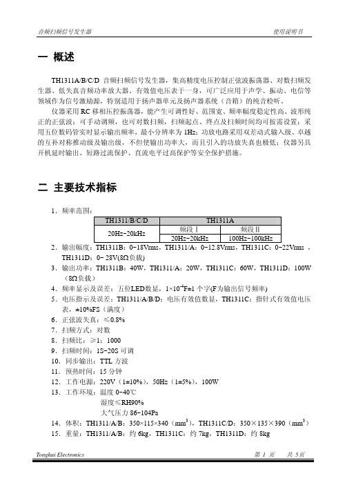
TH1311系列说明书

7
手动开关 将输出及频率显示切换至手动调节方式
8
频率显示窗口 采用五位 LED 数字显示
TH1311/B/C/D 只使用 Hz 一种单位,而 TH1311A 的频段Ⅱ
9
单位指示
约以 10kHz 为界,小于 10kHz 时以 Hz 为单位,大于 10kHz
时以 kHz 为单位,并配合有小数点显示
10 手动调频电位器 手动调节输出频率
6.正弦波失真:≤0.8%
7.扫频方式:对数
8.扫频比:≥1:1000
9.扫频时间:1S~20S 可调
10.同步输出:TTL 方波
11.预热时间:15 分钟
12.工作电源:220V(1±10%),50Hz(1±5%),100W
13.工作环境:温度 0~40℃
湿度≤RH90%
大气压力 86~104Pa
终点调节器,则有助于减小这一矛盾——终点调节相当于粗调,始点调节相当于微
调。
6.对于 TH1311A,当使用 100Hz~100kHz 档时,10kHz 是进行自动单位及小数点切换
的分界点,当您需要手调至 10kHz 附近某一频率点时,建议使用 20kHz 档。
7.为避免被测扬声器和仪器受到损坏,调节输出电压幅度前,应估算输出功率不至于
3
电压表
值(TH1311/A/B/D)
指示输出正弦波的电压幅度,指示值为有效值(TH1311C)
4
始点开关
将输出及频率显示切换至始点值,扫频的始点及手调的最 小频率对应于该值
5
终点开关
将输出及频率显示切换至终点值,扫频的终点及手调的最 大频率对应于该值
6
扫频开关
将输出及频率显示切换至对数扫频方式,只有终点频率大 于始点频率时,扫频才能进行
傅立叶变换红外光谱仪技术指标_33079解析

傅立叶变换红外光谱仪技术指标:一、FTIR 光谱仪主机1.1 干涉仪:平面镜电磁驱动迈克尔逊干涉仪,具有连续动态调整功能,无需光学补偿。
自动优化系统能量,无需人工调整。
1.2 光谱范围:7,800-350cm -11.3 检测器:DLaTGS ,对针定位,方便拆装。
1.4 光源:长寿命、高能量空冷中/远红外光源,预准直、对针定位、无需工具调整,3秒钟可达到稳定。
1.5 光谱分辨率:优于0.8 cm -1,可选0.5cm -11.6 波数精度:优于0.01cm -11.7 峰-峰噪音值:小于1×10⁻⁵AU (信噪比:40000:1)(1分钟扫描,KBr 分束器,DTGS检测器,4cm -1光谱分辨率)1.8 永久准直光路:光学台采用永久准直光路设计,无需用户在使用过程中进行人工调整。
所有元件均采用对针定位方式,即插即用,淘汰螺栓弹簧定位方式。
用户可自行在外部更换光源、电源、密封窗片,实现低成本维护1.9 密封干燥光学仓设计,带特殊防雾化设计窗片,内置湿度/温度诊断系,1.10 干燥功能:采用指示计来指示湿度变化情况,干燥剂可重复使用并且容易更换1.11 标准配置系统性能自动验证功能,包括硬件诊断,NIST 可溯源PS标准片,依据ASTME1421方法进行各种性能验证,如:文档运行、系统适应性诊断、性能验证、附件光通量、谱图质量等多项功能检验。
以确保谱图质量连续最优化。
1.12 可移动大样品仓设计,可配置各种附件供应商的不同附件,该附件也可以适用于不同的仪器,可配置10cm 光程的气体池、液体池;自动确认智能附件参数。
1.13 数据接口:USB2.0高速通讯接口,可通过USB 接口连接手提电脑。
二、操作软件:与Windows Win7兼容,功能包括数据采集、数据处理、谱库检索等。
要求全部汉化,可用中文对谱图进行标注。
实时显示系统当前所处的状态,并实时给出主要元器件的电流、电压、温度值,指示出故障问题,指导使用者如何解决故障问题。
BT131W-600四极体数据手册说明书

BT131W-6004Q Triac15 June 2016Product data sheet1. General descriptionPlanar passivated four quadrant triac in a SOT223 surface-mountable plastic package intended foruse in applications requiring high bidirectional transient and blocking voltage capability and highthermal cycling performance.2. Features and benefits•High blocking voltage capability•Planar passivated for voltage ruggedness and reliability•Surface-mountable package•Triggering in all four quadrants•Very sensitive gate3. Applications•General purpose low power motor control•General purpose switching and phase control4. Quick reference data5. Pinning information6. Ordering information7. Limiting values Table 4. Limiting values8. Thermal characteristics9. CharacteristicsT j (°C)-50150100050003aab0430.81.21.60.4V GT(Tj)V GT(25°C)Fig. 13. Normalized gate trigger voltage as a function of junction temperature 003aab046T j (°C)01501005010210103dV D /dt (V/µs)1Fig. 14. Rate of rise of off-state voltage as a function of junction temperature; typical values10. Package outline11. Package outline (minimized)12. Soldering13. Legal informationData sheet status[1]Please consult the most recently issued document before initiating orcompleting a design.[2]The term 'short data sheet' is explained in section "Definitions".[3]The product status of device(s) described in this document may havechanged since this document was published and may differ in case ofmultiple devices. The latest product status information is available onthe Internet at URL .DefinitionsDraft — The document is a draft version only. The content is still under internal review and subject to formal approval, which may result in modifications or additions. WeEn Semiconductors does not give any representations or warranties as to the accuracy or completeness of information included herein and shall have no liability for the consequences of use of such information.Short data sheet — A short data sheet is an extract from a full data sheet with the same product type number(s) and title. A short data sheet is intended for quick reference only and should not be relied upon to contain detailed and full information. For detailed and full information see the relevant full data sheet, which is available on request via the local WeEn Semiconductors sales office. In case of any inconsistency or conflict with the short data sheet, the full data sheet shall prevail.Product specification — The information and data provided in a Product data sheet shall define the specification of the product as agreed between WeEn Semiconductors and its customer, unless WeEn Semiconductors and customer have explicitly agreed otherwise in writing. In no event however, shall an agreement be valid in which the WeEn Semiconductors productis deemed to offer functions and qualities beyond those described in the Product data sheet.DisclaimersLimited warranty and liability — Information in this document is believedto be accurate and reliable. However, WeEn Semiconductors does notgive any representations or warranties, expressed or implied, as to the accuracy or completeness of such information and shall have no liability for the consequences of use of such information. WeEn Semiconductors takes no responsibility for the content in this document if provided by an information source outside of WeEn Semiconductors.In no event shall WeEn Semiconductors be liable for any indirect, incidental, punitive, special or consequential damages (including - without limitation -lost profits, lost savings, business interruption, costs related to the removal or replacement of any products or rework charges) whether or not such damages are based on tort (including negligence), warranty, breach of contract or any other legal theory.Notwithstanding any damages that customer might incur for any reason whatsoever, WeEn Semiconductors’ aggregate and cumulative liability towards customer for the products described herein shall be limited in accordance with the Terms and conditions of commercial sale of WeEn Semiconductors.Right to make changes — WeEn Semiconductors reserves the right to make changes to information published in this document, including without limitation specifications and product descriptions, at any time and without notice. This document supersedes and replaces all information supplied prior to the publication hereof.Suitability for use — WeEn Semiconductors products are not designed, authorized or warranted to be suitable for use in life support, life-criticalor safety-critical systems or equipment, nor in applications where failureor malfunction of an WeEn Semiconductors product can reasonablybe expected to result in personal injury, death or severe property or environmental damage. WeEn Semiconductors and its suppliers accept no liability for inclusion and/or use of WeEn Semiconductors products in such equipment or applications and therefore such inclusion and/or use is at the customer’s own risk.Quick reference data — The Quick reference data is an extract of the product data given in the Limiting values and Characteristics sections of this document, and as such is not complete, exhaustive or legally binding. Applications — Applications that are described herein for any of these products are for illustrative purposes only. WeEn Semiconductors makesno representation or warranty that such applications will be suitable for the specified use without further testing or modification.Customers are responsible for the design and operation of their applications and products using WeEn Semiconductors products, and WeEn Semiconductors accepts no liability for any assistance with applications or customer product design. It is customer’s sole responsibility to determine whether the WeEn Semiconductors product is suitable and fit for the customer’s applications and products planned, as well as for the planned application and use of customer’s third party customer(s). Customers should provide appropriate design and operating safeguards to minimize the risks associated with their applications and products.WeEn Semiconductors does not accept any liability related to any default, damage, costs or problem which is based on any weakness or defaultin the customer’s applications or products, or the application or use by customer’s third party customer(s). Customer is responsible for doing all necessary testing for the customer’s applications and products using WeEn Semiconductors products in order to avoid a default of the applicationsand the products or of the application or use by customer’s third party customer(s). WeEn does not accept any liability in this respect.Limiting values — Stress above one or more limiting values (as defined in the Absolute Maximum Ratings System of IEC 60134) will cause permanent damage to the device. Limiting values are stress ratings only and (proper) operation of the device at these or any other conditions above thosegiven in the Recommended operating conditions section (if present) or the Characteristics sections of this document is not warranted. Constant or repeated exposure to limiting values will permanently and irreversibly affect the quality and reliability of the device.No offer to sell or license — Nothing in this document may be interpreted or construed as an offer to sell products that is open for acceptance or the grant, conveyance or implication of any license under any copyrights, patents or other industrial or intellectual property rights.Export control — This document as well as the item(s) described herein may be subject to export control regulations. Export might require a prior authorization from competent authorities.Non-automotive qualified products — Unless this data sheet expressly states that this specific WeEn Semiconductors product is automotive qualified, the product is not suitable for automotive use. It is neither qualified nor tested in accordance with automotive testing or application requirements. WeEn Semiconductors accepts no liability for inclusion and/or use of non-automotive qualified products in automotive equipment or applications.In the event that customer uses the product for design-in and use in automotive applications to automotive specifications and standards, customer (a) shall use the product without WeEn Semiconductors’ warranty of the product for such automotive applications, use and specifications, and (b) whenever customer uses the product for automotive applications beyond WeEn Semiconductors’ specifications such use shall be solely at customer’s own risk, and (c) customer fully indemnifies WeEn Semiconductors forany liability, damages or failed product claims resulting from customer design and use of the product for automotive applications beyond WeEn Semiconductors’ standard warranty and WeEn Semiconductors’ product specifications.Translations — A non-English (translated) version of a document is for reference only. The English version shall prevail in case of any discrepancy between the translated and English versions.TrademarksNotice: All referenced brands, product names, service names and trademarks are the property of their respective owners.14. Contents1. General description (1)2. Features and benefits (1)3. Applications (1)4. Quick reference data (1)5. Pinning information (2)6. Ordering information (2)7. Limiting values (3)8. Thermal characteristics (6)9. Characteristics (8)10. Package outline (11)11. Package outline (minimized) (12)12. Soldering (12)13. Legal information (14)© WeEn Semiconductors Co., Ltd. 2016. All rights reservedFor more information, please visit: Forsalesofficeaddresses,pleasesendanemailto:**************************** Date of release: 15 June 2016。
心脏电信号检测仪[实用新型专利]
![心脏电信号检测仪[实用新型专利]](https://img.taocdn.com/s3/m/8faa4a9bf242336c1fb95e6f.png)
专利名称:心脏电信号检测仪专利类型:实用新型专利
发明人:徐国强
申请号:CN88220388.6
申请日:19881203
公开号:CN2045991U
公开日:
19891018
专利内容由知识产权出版社提供
摘要:本实用新型涉及一种心脏电信号检测仪。
它是临床诊断、治疗心脏病、心脏电生理研究的专用仪器。
它由电极、转接盒、前置放大器、滤波器、电压放大、跟随器、隔离器、输出匹配器、显示电路、直流电源、校正信号源及记录控制电路等组成,其特点是除了同时记录四路心房、室信号外,还有一路窦房结电图检测电路和一路希氏束电图检测电路。
它对诊断、治疗窦房病变和心脏传导系统电生理变化具有独特作用。
申请人:徐国强
地址:北京市海淀区西翠路3号院9-3-501号
国籍:CN
更多信息请下载全文后查看。
- 1、下载文档前请自行甄别文档内容的完整性,平台不提供额外的编辑、内容补充、找答案等附加服务。
- 2、"仅部分预览"的文档,不可在线预览部分如存在完整性等问题,可反馈申请退款(可完整预览的文档不适用该条件!)。
- 3、如文档侵犯您的权益,请联系客服反馈,我们会尽快为您处理(人工客服工作时间:9:00-18:30)。
FTT131分布式高频录波仪产品说明书
须知
目录
1产品概述 (4)
2FTT131分布式高频录波仪技术指标 (4)
2.1供电电源与环境要求 (4)
2.2同步采样模拟通道 (5)
2.3同步采样开关量通道 (5)
2.4长时间记录波形时长 (5)
2.5故障启动方式 (5)
2.6录波存储容量 (6)
2.7GPS对时 (6)
2.8通信接口 (6)
3FTT131分布式高频录波仪主要功能 (6)
4结构尺寸 (7)
1产品概述
故障录波仪主要用于记录和分析电力系统发生故障前后相关电参数的变化过程及开关动作行为的装置的设备,利用其在故障前后一段时间记录的系统运行数据可以很方便地查出故障原因,也可作为故障反演时作为特征波形的重要数据来源。
传统的故障录波仪以单装置最多可采集96个模拟量、192个开关量的集中式故障录波装置为主,且受数据传输速率与存储容量的限制,不能对电信号或开关信号进行高采样率下的长时间录波,这给事后的故障分析带来很大的麻烦,同时集中式录波也不便于用于故障反演。
FTT131分布式高频录波仪就是为了解决上述问题而研制的。
FTT131分布式高频录波仪具有以下特点:
➢全通道高采样率采集与录波
➢高精度采集与录波
➢长时间连续录波
➢故障波形持续时间可编辑
➢支持多种录波触发方式
➢高精度IRIG-B对时
➢便携式设计,体积小,重量轻
2FTT131分布式高频录波仪技术指标
2.1供电电源与环境要求
➢电源供电方式:AC200V~240V
➢功耗:不大于50W
➢额定工作环境:-10℃~+50℃,湿度≤95%,无凝结
➢存储环境要求:温度-20℃~+70℃,平均湿度≤90%,无凝结
2.2同步采样模拟通道
➢A/D分辨率:16位
➢有效值计算精度:0.1%
➢采样精度:0.1%
➢相位精度:±0.1°
➢频率误差:±0.001Hz
➢模拟通道数:4路电压与4路电流
2.3同步采样开关量通道
➢通道数:8路
➢开关量分辨率:0.1ms
➢信号类型:无源结点
2.4长时间记录波形时长
典型配置的8套FTT131分布式高频记录仪与1台录波服务器在全通道同步采样、采样率为100kHz时的记录时间为24小时。
几种典型配置录波时长如表1所示:
表1 典型配置连续录波时长
2.5故障启动方式
➢模拟量启动
瞬时值、有效值、频率的过量、欠量、突变量启动。
➢开关量变位启动
➢定时启动
用户可通过软件任意设定录波启动时间。
➢手动启动
用户可通过软件设定手动启动是否使能。
➢高级启动
正序、负序、零序的过量、欠量启动等。
2.6录波存储容量
单台录波服务器最大可支持1.8T的存储容量。
2.7GPS对时
支持高精度IRIG-B对时。
2.8通信接口
(1)网口:2路标准RJ45接口,10/100M自适应。
(2)串口: 2路RS485,用于IRIG-B对时。
3FTT131分布式高频录波仪主要功能
➢全通道高采样率采集与录波
本产品支持对8个模拟量通道与8个开光量的同步采集与录波,且采样率最高可达100kHz。
➢高精度采集与录波
波形采集精度高,有效值精度达到0.1%,相位精度达±0.1°,频率精度达±0.005H z。
➢长时间连续录波
本装置支持长时间的连续录波,对于本产品的典型配置,在100kHz采样率下可连续录波24h。
➢故障波形持续时间可编辑
可自定义触发前后录波时间,将录波启动前一段时间的信号波形完整连续地记录下来。
➢支持多种录波触发方式
具备手动启动连续录波、定时触发录波、遥信变位录波、模拟量启动录波、正序、负序、零序电压或电流越限录波等多种录波触发方式。
➢高精度IRIG-B对时
本产品支持高精度IRIG-B对时功能。
4结构尺寸
FTT131分布式高频录波仪尺寸(W*H*D):482.6*373.98*132.5(mm)。
图 1 FTT131分布式高频录波仪结构示意图。
