LSI SAS 1068E RAID配置说明
LSI RAID
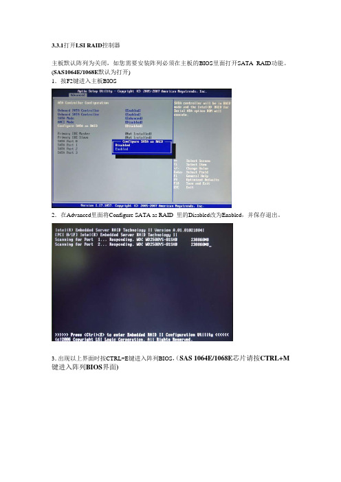
3.3.1打开LSI RAID控制器主板默认阵列为关闭,如您需要安装阵列必须在主板的BIOS里面打开SATA RAID功能。
(SAS1064E/1068E默认为打开)1.按F2键进入主板BIOS2.在Advanced里面将Configure SATA as RAID 里的Disabled改为Enabled,并保存退出。
3.出现以上界面时按CTRL+E键进入阵列BIOS,(SAS 1064E/1068E芯片请按CTRL+M 键进入阵列BIOS界面)1.在主菜单下选第一项Configure,按Enter,弹出以下界面2.Easy Configuration:简单配置阵列New Configuration:配置新的阵列View/Add Configuration:校验/添加阵列信息Clear configuration:清除阵列信息Select Boot Drive:选择引导驱动器(如有两组RAID可以选取)我们这里选取第一项Easy Configuration,(如果您的硬盘不是全新的,您这里需要选取第四项Clear Configuration,清除阵列信息后再安装新的阵列信息)弹出以下界面3.按SPACE选择要做阵列的磁盘后按F10,弹出以下界面4.按SPACE后再按F10,弹出以下界面5.RAID=(根据需要可选择RAID0或RAID1)Size=(阵列容量)DWC=(默认)RA=(默认)AcceptSPAN=(黙认)在Accept(接受)按Enter键,弹出以下界面6.这里选择主盘,如果是新的硬盘可以随便选取一个,如果您的一个硬盘里面有数据(这里说的是数据而非阵列信息)并且希望数据能做RAID1时保留下来,(做RAID0时没有此菜单)就需要慎重选择(比喻:您是A00-00里面有数据,而且希望将A00-00里面的数据备份到A00-01里面去,这里您就要选择ONLIN A00-01)选完后按Enter弹出以下界面7.是否保存配置,选是按Enter后新的阵列做好了。
lsi_1068_IR配置方法
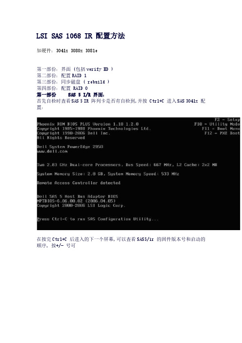
LSI SAS 1068 IR 配置方法如硬件:3041x 3080x 3081e第一部份:界面 (包括verify HD )第二部份:配置RAID 1第三部份:同步磁盘 ( rebuild )第四部份:配置 RAID 0第一部份 SAS 5 I/R 界面:首先自检时查看SAS 5 IR 阵列卡是否有自检到,并按 Ctrl+C 进入SAS 3041x 配置:在按完Ctrl+C 后进入的下一个屏幕,可以查看SAS5/ir 的固件版本号和启动的顺序,按+/- 号可以更改启动顺序,ins/del 键可以更改启动列表,直接按回车进入配置界面:在这个界面中可以查看/设置 RAID (RAID Properties )查看/设置 SAS 拓朴 ( SAS Topology )或是查看/设置适配卡的高级属性(Advanced AdapterProperties )先查看 SAS 的拓朴,在这里面可以查看到SAS 5 I/R 阵列卡中一共插了三块硬盘按Alt+D 可以查看设备的具体属性(包括对此块硬盘进行 Verify !)主界面的查看/设置适配卡的高级属性 (Advanced Adapter Properties ) 在Advanced Adapter Properties 中有以下这里面有一项 PHY 属性很重要,就是 Discovery Status 它可以显示一些SAS 链路/协议上的一些问题第二部份配置RAID1:在主界面选择 RAID Properties 进行阵列卡配置:在RAID 配置界面中有三个选择项:查看已经存在的阵列配置(此选项只有在已经存在阵列配置的情况下才出会现)通常在第一次配置阵列时,只会出现下面两项创建 IM (镜像) 卷 (做RAID 1 ) (最多只允许两块硬盘做RAID1)创建IS ( 条带)卷(做RAID 0 )(最少2块,最多4块硬盘做RAID0)创建RAID 1 (选择 Create IM Volume )将光标移动到第一块硬盘的RAID Disk 栏上,按空格键选中这块磁盘,这时驱动器状态成 Primary (主盘)Drive Status 有以下几种:具体说明可以查最上面的用户手册链接:然后将光标移动到第二块磁盘的 RAID Disk 处,按空格选中这时会出现一个警告提示,大意是如果继续将这块硬盘加入阵列中,这块盘上原先的数据将会被抹除,按C 后,可以成功的创建RAID 1系统会自动提示是否需要保存RAID 的配置,选择保存退出再按F3 确认后就可以成功的创建RAID 1了。
LSI SAS 1068E RAID配置说明
LSI SAS 1068E RAID配置说明
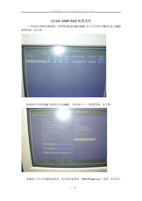
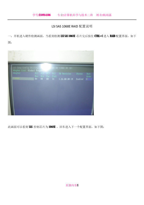
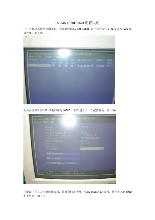
一:开机进入硬件检测画面,当看到检测LSI SAS 1068E 芯片完后按住CTRL+C进入RAID 配置界面,如下图:
此画面可以看到SAS 控制芯片为1068E ,回车进入下一个配置界面,如下图:
用键盘上左右方向键选择选项,此时我们选择到“RAID Properties”选项,回车进入
到RAID配置界面,如下图:
如上图所示:第一选项为创建RAID1镜像(Creat IM volume).第二选项为创建RAID1E (Creat IME volume)第三选项为创建RAID0(Creat IS volume).选择你所需要创建的RAID 模式,按回车键进入下一个配置界面,如下图:
用键盘左右方向键选择到“RAID Disk”选项按空格键选择硬盘,选择完硬盘后按C
键创建RAID。
创建完后进入下一界面,如下图:
此时选择保存退出。
到此RAID创建完毕。
1608E配置指南
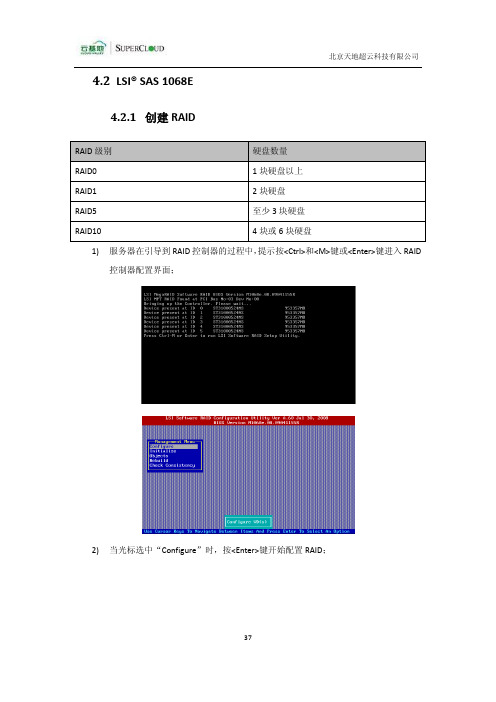
4.2LSI® SAS 1068E4.2.1创建RAID1)服务器在引导到RAID控制器的过程中,提示按<Ctrl>和<M>键或<Enter>键进入RAID控制器配置界面;2)当光标选中“Configure”时,按<Enter>键开始配置RAID;3)利用方向键向下移动光标到“New Configuration”,按<Enter>键弹出确认对话框,选择“Yes”执行创建RAID操作;4)按<Space>键选择RAID卷组所要包含的磁盘;RAID0至少选中其中一块硬盘,最多可选择所有物理硬盘,按<Space>键选择一块或多块,选择完毕后按两次<Enter>键结束选择弹出选择配置卷组对话框;按<Space>键选中配置卷组;按<F10>开始配置向导,RAID Level值选择RAID0,其他配置选项直接按<Enter>键选择默认值;弹出下图界面时,按<F10>结束RAID配置;弹出确认保存对话框,选择“Yes”保存RAID配置,RAID创建成功;RAID1按<Space>选中其中两块硬盘,选择完毕后按两次<Enter>键结束选择弹出选择配置卷组对话框;按<Space>键选中配置卷组;按<F10>开始配置向导,RAID Level值选择RAID1,其他配置选项直接按<Enter>键选择默认值;弹出下图界面时,按<F10>结束RAID配置;弹出确认保存对话框,选择“Yes”保存RAID配置,RAID创建成功;RAID5至少选中其中三块硬盘,最多可选择所有物理硬盘,按<Space>键选择三块或多块,选择完毕后按两次<Enter>键结束选择弹出选择配置卷组对话框;按<Space>键选中配置卷组;按<F10>开始配置向导,RAID Level值选择RAID5,其他配置选项直接按<Enter>键选择默认值;弹出下图界面时,按<F10>结束RAID配置;弹出确认保存对话框,选择“Yes”保存RAID配置,RAID创建成功;RAID10选中其中四块或六块硬盘按<Space>键选择四块或六块,选择完毕后按两次<Enter>键结束选择弹出选择配置卷组对话框;按<Space>键选中配置卷组;按<F10>开始配置向导,RAID Level值选择RAID10,其他配置选项直接按<Enter>键选择默认值;弹出下图界面时,按<F10>结束RAID配置;弹出确认保存对话框,选择“Yes”保存RAID配置,RAID创建成功;4.2.2删除RAID1)利用方向键向下移动光标到“Clear Configuration”,按<Enter>键弹出确认对话框;2)选择“Yes”执行删除RAID操作;3)光标选中View/Add Configuration,按<Enter>键;4)列出单盘READY状态而非RAID卷组ONLIN状态,表明RAID删除成功;4.2.3重建RAID当RAID由于磁盘损坏或者其他原因而引起RAID掉盘问题,需要重建RAID才能保证数据安全。
LSI SAS 1068E RAID配置说明
LSI SAS 1068E RAID配置说明
一:开机进入硬件检测画面,当看到检测LSI SAS 1068E 芯片完后按住CTRL+C进入RAID配置界面,如下图:
此画面可以看到SAS 控制芯片为1068E ,回车进入下一个配置界面,如下图:
页脚内容1
用键盘上左右方向键选择选项,此时我们选择到“RAID Properties”选项,回车进入到RAID配置界面,如下图:
页脚内容2
如上图所示:第一选项为创建RAID1镜像(Creat IM volume).第二选项为创建RAID1E(Creat IME volume)第三选项为创建RAID0(Creat IS volume).选择你所需要创建的RAID模式,按回车键进入下一个配置界面,如下图:
页脚内容3
用键盘左右方向键选择到“RAID Disk”选项按空格键选择硬盘,选择完硬盘后按C键创建RAID。
创建完后进入下一界面,如下图:
页脚内容4
此时选择保存退出。
到此RAID创建完毕。
页脚内容5。
LSI存储服务器RAID操作说明
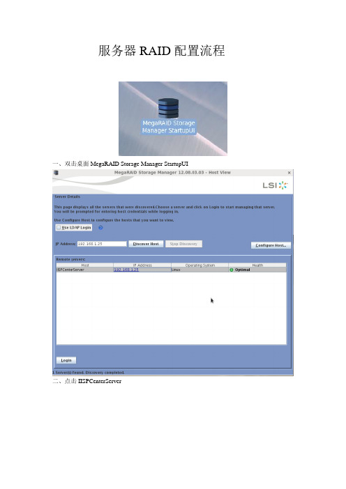
服务器RAID配置流程一、双击桌面MegaRAID Storage Manager StartupUI二、点击IISPCenterServer.三、打开管理软件,弹出登陆界面,输入名称和密码(名称和密码是本机的用户名和密码)四、进入管理软件后点Logical菜单,右键RAID卡,选创建RAID(Create Virtual Drive).五、选Advanced,点Next..六、先选择RAID Level(RAID 级别),再Select unconfigured driverl 里添加硬盘(点Add 添加), 点Create Drive Group.七、要是做磁盘热备,点上剩余硬盘和作的RAID 组,点Add Hot Spare(添加热备盘),没有热备就省略这步,点Next.(12)Virtual drive name(卷的名称) : 默认Capacity(容量)Initialization state(初始化状态): Full Initialization(全部初始化)Stripe size(条纹大小): 64KB Read Policy(读策略): Adaptive Read Ahead(自适应读策略) Write Policy(写策略): Always Write Back(总是回写)I/O Policy(I/O策略): Cached IO(IO缓存) Access Policy(访问策略): Read Write(读写) Disk cache Policy(磁盘高速缓存策略): Disabled(关闭)点Create Virtual Drive.八、弹出对话框,点Yes..十、查看RAID 进度,点Manage 菜单里的Show Progress.完成好了,在我的电脑-管理-磁盘管理,格式化磁盘就可以使用了。
LSI RAID配置手册(图文)
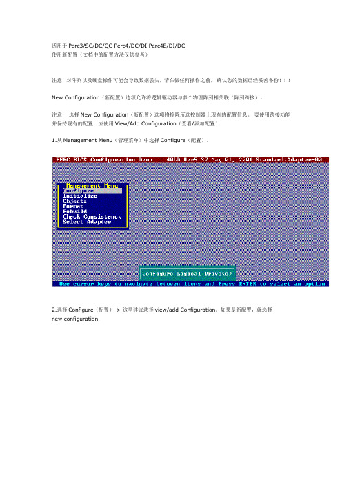
适用于Perc3/SC/DC/QC Perc4/DC/DI Perc4E/DI/DC使用新配置(文档中的配置方法仅供参考)注意:对阵列以及硬盘操作可能会导致数据丢失,请在做任何操作之前,确认您的数据已经妥善备份!!!New Configuration(新配置)选项允许将逻辑驱动器与多个物理阵列相关联(阵列跨接)。
注意:选择New Configuration(新配置)选项将擦除所选控制器上现有的配置信息。
要使用跨接功能并保持现有的配置,应使用View/Add Configuration(查看/添加配置)1.从Management Menu(管理菜单)中选择Configure(配置)。
2.选择Configure(配置)-> 这里建议选择view/add Configuration。
如果是新配置,就选择new configuration.阵列选择窗口显示与当前控制器相连接的设备。
屏幕底部显示热键信息。
热键具有以下功能:<F2> 显示所选逻辑驱动器的驱动器数据和PERC4/Di错误计数。
<F3> 显示已经配置的逻辑驱动器。
<F4> 指定所选的驱动器为热备份。
<F10> 显示逻辑驱动器配置屏幕。
3.按箭头键突出显示特定的物理驱动器。
只有状态是READY的硬盘可以被选择,使用New Configuration 会将所有的硬盘状态变为READY,所以原先的RAID信息以及数据都会丢失!!!图中ID 3:PROC是RAID控制器本身。
4.按空格键将所选的物理驱动器与当前阵列相关联。
5.所选驱动器的指示灯从READY(就绪)更改为ONLINE(联机)A[阵列号]-[驱动器号]。
例如,ONLINE (联机)A2-3表示阵列2中的磁盘驱动器3 。
注意:使用具体阵列中容量相同的驱动器。
如果使用的驱动器容量不相同,则阵列中所有驱动器的容量都被看作和阵列中最小驱动器的容量一样大小。
浪潮英信服务器 说明书
尊敬的浪潮英信服务器用户:衷心感谢您选用了浪潮英信服务器!本手册介绍了本浪潮英信服务器的技术特性与系统的设置、安装,有助于您更详细地了解和便捷地使用此款浪潮英信服务器。
请将我方产品的包装物交废品收购站回收利用,以利于污染预防,造福人类。
浪潮集团有限公司拥有本手册的版权。
未经浪潮集团有限公司许可,任何单位和个人不得以任何形式复制本用户手册。
浪潮集团有限公司保留随时修改本手册的权利。
本手册中的内容如有变动恕不另行通知。
如果您对本手册有疑问或建议,请向浪潮集团有限公司垂询。
浪潮集团有限公司 2007年10月“Inspur浪潮”、“英信”是浪潮集团有限公司的注册商标。
其他商标分别属于其相应的注册公司。
声 明在您正式使用本服务器之前,请先阅读以下声明。
只有您阅读了以下声明并且同意以下各条款后,方可正式开始使用本服务器;如果您对以下条款有任何疑问,请和您的供货商联系或直接与我们联系。
如您未向我们就以下条款提出疑问并开始使用本服务器,则是默认您已经同意了以下各条款。
1.我们提醒您特别注意:在任何时候,除了我们提示您可以修改的参数以外,您不要修改本服务器主板BIOS中的任何其他参数。
2.在您使用的服务器出现任何硬件故障时或您希望对硬件进行任何升级时,请将您机器的详细硬件配置反映给我们的客户服务中心;请您不要自行拆卸服务器机箱及机箱内任何硬件设备。
3.本服务器的内存、CPU、CPU散热片、风扇、硬盘托架、硬盘等都是特殊规格的,请您不要将它们和任何其他型号机器的相应设备混用。
4.您在使用服务器过程中遇到的任何软件问题,我们希望您首先和相应软件的提供商联系,由他和我们联系,以方便我们沟通、共同解决您碰到的问题。
对于如数据库、网络管理软件或其他网络产品等的安装、运行问题,我们尤其希望您能够这样处理。
5.如果上架安装本服务器,请先仔细阅读随机的快速使用指南。
如果您有任何使用疑难问题,请与我们的客户服务中心联系。
6.我们特别提醒您:在使用过程中,注意对您的数据进行必要的备份。
LSI SAS 1068E RAID配置说明
LSI SAS 1068E RAID配置说明
一:开机进入硬件检测画面,当看到检测LSI SAS 1068E 芯片完后按住CTRL+C进入RAID配置界面,如下图:
此画面可以看到SAS 控制芯片为1068E ,回车进入下一个配置界面,如下图:
用键盘上左右方向键选择选项,此时我们选择到“RAID Properties”选项,回车进入到RAID 配置界面,如下图:
如上图所示:第一选项为创建RAID1镜像(Creat IM volume).第二选项为创建RAID1E(Creat IME volume)第三选项为创建RAID0(Creat IS volume).选择你所需要创建的RAID模式,按回车键进入下一个配置界面,如下图:
用键盘左右方向键选择到“RAID Disk” 选项按空格键选择硬盘,选择完硬盘后按C键创建RAID。
创建完后进入下一界面,如下图:
此时选择保存退出。
到此RAID创建完毕。
LSI RAID配置手册(图文)

适用于Perc3/SC/DC/QC Perc4/DC/DI Perc4E/DI/DC使用新配置(文档中的配置方法仅供参考)注意:对阵列以及硬盘操作可能会导致数据丢失,请在做任何操作之前,确认您的数据已经妥善备份!!!New Configuration(新配置)选项允许将逻辑驱动器与多个物理阵列相关联(阵列跨接)。
注意:选择New Configuration(新配置)选项将擦除所选控制器上现有的配置信息。
要使用跨接功能并保持现有的配置,应使用View/Add Configuration(查看/添加配置)1.从Management Menu(管理菜单)中选择Configure(配置)。
2.选择Configure(配置)-> 这里建议选择view/add Configuration。
如果是新配置,就选择new configuration.阵列选择窗口显示与当前控制器相连接的设备。
屏幕底部显示热键信息。
热键具有以下功能:<F2> 显示所选逻辑驱动器的驱动器数据和PERC4/Di错误计数。
<F3> 显示已经配置的逻辑驱动器。
<F4> 指定所选的驱动器为热备份。
<F10> 显示逻辑驱动器配置屏幕。
3.按箭头键突出显示特定的物理驱动器。
只有状态是READY的硬盘可以被选择,使用New Configuration 会将所有的硬盘状态变为READY,所以原先的RAID信息以及数据都会丢失!!!图中ID 3:PROC是RAID控制器本身。
4.按空格键将所选的物理驱动器与当前阵列相关联。
5.所选驱动器的指示灯从READY(就绪)更改为ONLINE(联机)A[阵列号]-[驱动器号]。
例如,ONLINE (联机)A2-3表示阵列2中的磁盘驱动器3 。
注意:使用具体阵列中容量相同的驱动器。
如果使用的驱动器容量不相同,则阵列中所有驱动器的容量都被看作和阵列中最小驱动器的容量一样大小。
LSI-阵列卡操作手册
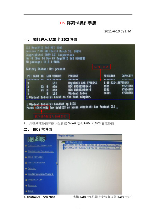
LIS 阵列卡操作手册2011-4-10by LFM一、如何进入RAID 卡BIOS 界面1、开机到此界面时按下组合键Ctrl+H 进入RAID 卡BIOS 管理界面。
二、BIOS主界面1、Controller Selection 选择RAID 卡(机器上安装有多张RAID 卡时)按下组合键进入BIOS 界面阵列卡信息2、Controller Properties RAID卡属性设置3、Scan Devices刷新硬盘设备,4、Virtual Drives虚拟磁盘管理,设置阵列引导顺序-选择要引导的阵列-选择-set boot drive〔currnet=0〕后点GO5、Drives物理硬盘管理6、Configuration Wizard创建阵列配置(配置向导)7、Logical View/Physical View查看逻辑/物理磁盘(点击切换)8、Events事件日志9、Exit退出三、创建阵列1、查看物理硬盘在界面右面可看到可用于做RAID的硬盘○1Slot:0——为硬盘的物理位置,在0号端口。
○2Unconfigured Good——好的,未配置的硬盘。
2、点击“Configuration Wizard ”进入创建阵列配置,如图:12○1Clear Configuration清除所有的阵列配置信息○2New Configuration新建RAID配置(会清除所有的数据,一般只在新机器第一次做阵列时选择)○3Add Configuration曾加RAID配置3、一般选择Add Configuration,按Nex t 进入下一步:12○1Manual Configuration手动配置○2Automatic Configuration自动配置3、选Manual Configuration 手动配置进入下一步:12○1在左边“Drives”框中选择要做RAID的磁盘,按住Ctrl键可一次同时几个。
配置LSI1064E 1068 1078 2008 RAID图文
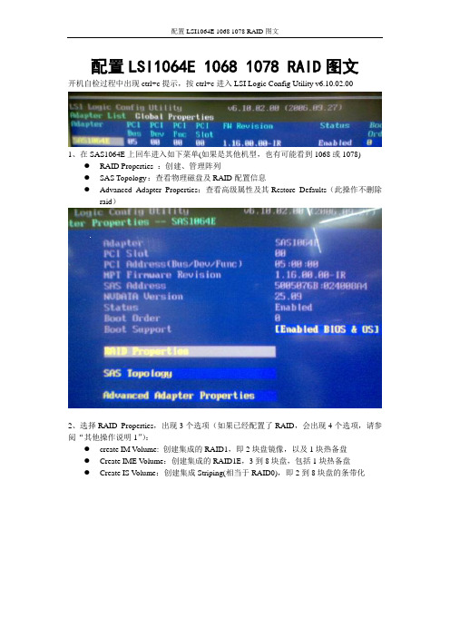
配置LSI1064E 1068 1078 RAID图文开机自检过程中出现ctrl+c提示,按ctrl+c进入LSI Logic Config Utility v6.10.02.001、在SAS1064E上回车进入如下菜单(如果是其他机型,也有可能看到1068或1078)●RAID Properties :创建、管理阵列●SAS Topology :查看物理磁盘及RAID配置信息●Advanced Adapter Properties:查看高级属性及其Restore Defaults(此操作不删除raid)2、选择RAID Properties,出现3个选项(如果已经配置了RAID,会出现4个选项,请参阅“其他操作说明1”):●create IM V olume: 创建集成的RAID1,即2块盘镜像,以及1块热备盘●Create IME V olume:创建集成的RAID1E,3到8块盘,包括1块热备盘●Create IS V olume:创建集成Striping(相当于RAID0),即2到8块盘的条带化3、选择create IM V olume,出现如下create new array--SAS1064E的菜单:光标移动到第一块盘,RAID DISK下方[NO],(配置raid前为No),按空格/减号,弹出一个菜单:●M 保留数据,并迁移到新建的RAID1● D 删除数据,创建一个全新的RAID1选择M,之后返回上级菜单,RAID DISK状态变为Yes4、接着光标移动到第二块盘,RAID DISK下方[NO],按空格/减号,使其RAID DISK状态变为Yes5、按C,创建阵列6、选Save changes then exit this menu。
退出RAID1的配置,同步会自动在后台开始执行。
其他操作说明:1、配置过RAID之后,进入RAID Properties会多出一行选择:View Existing Array:●View Existing Array: 查看已有阵列●Create IM V olume: 创建集成的RAID1,即2块盘镜像,以及1块热备盘●Create IME Volume:创建集成的RAID1E,3到8块盘,包括1块热备盘●Create IS Volume:创建集成Striping,即2到8块盘的条带化选择View Existing Array--〉Manage Array(这里可以看到同步进度)出现如下菜单:●Manage Hot Spare:配置热备盘●Synchronize Array (Y:开始同步,N:放弃同步)●Activate Array :激活阵列●Delete Array :删除阵列2、主菜单:Adpater Properties--SAS1064E描述RAID Properties :创建、管理阵列SAS Topology:查看物理磁盘及RAID配置信息Alt+D=Device Properties可以格式化Advanced Adapter Properties:查看高级属性及其Restore Defaults(此操作不删除raid)3、tips:所有黄色菜单可选;白色的菜单不可选,如果选了就会出帮助信息。
曙光SAS RAID(HBA)卡配置工具与操作指南
前言感谢您选用曙光服务器,配置曙光服务器SAS RAID/HBA卡前请详细阅读本手册。
本手册主要介绍了RAID的功能以及对各RAID级别进行了解释;同时对于曙光服务器中的SAS RAID/HBA卡的配置进行了说明。
本手册主要包括如下三个部分:一、RAID简介及各RAID级别介绍;二、对基于LSI ROC1078 / 2108芯片的RAID卡的配置、操作系统下的管理工具的安装使用进行了介绍;三、对基于LSI SAS 1068E / 2008芯片的HBA卡的配置说明四、对基于PMC 8011芯片的曙光R8760 Raid卡的配置、操作系统下的管理工具的安装使用进行了介绍。
版权所有 ©2006 曙光信息产业有限公司。
本手册受版权法保护,本手册的任何部分未经曙光信息产业有限公司授权,不得擅自复制或转载。
本手册中提到的信息,如因产品升级或其他原因而导致变更,恕不另行通知。
“Lsilogic”及图标是LSI公司的注册商标。
其他注册商标均由其各自的商标持有人所有。
目录前言 -------------------------------------------------------------------------------- 1 第一章 Raid技术简介 --------------------------------------------------------- 41 Raid技术简介 ------------------------------------------------------------------------------------------ 42 Raid级别简介 ------------------------------------------------------------------------------------------ 43 Raid各级别的对比------------------------------------------------------------------------------------ 84 Raid术语简介 ------------------------------------------------------------------------------------------ 8 第二章 LSI Raid配置及管理软件介绍 ----------------------------------- 122.1 LSI Raid WebBIOS Configuration Utility配置向导------------------------------------------ 122.1.1 WebBIOS Configuration Utility简介 --------------------------------------------------- 122.1.2 如何进入WebBIOS Configuration Utility -------------------------------------------- 122.1.3 WebBIOS Configuration Utility 存储配置 -------------------------------------------- 142.1.3.1 自动配置:------------------------------------------------------------------------------- 152.1.3.2 自定义配置:---------------------------------------------------------------------------- 162.1.4 设置热备盘(Hot Spare)--------------------------------------------------------------- 202.1.5查看及修改相关配置信息---------------------------------------------------------------- 212.1.6 RAID 恢复 ---------------------------------------------------------------------------------- 272.2 MegaRaid Storage Manager 管理软件安装与使用 ------------------------------------------ 322.2.1 MegaRaid Storage manager在Windows下的安装 ---------------------------------- 322.2.2 MegaRaid Storage manager配置与使用 ----------------------------------------------- 362.2.3 MegaRaid Storage manager 管理软件在Linux系统下的安装与使用 -------- 44 第三章LSI SAS HBA配置说明 ------------------------------------------- 453.1 LSI MPT SAS(2) Configuration Utility配置向导--------------------------------------------- 453.1.1 RAID Properties ---------------------------------------------------------------------------- 463.1.2 SAS Topology ------------------------------------------------------------------------------- 493.1.3 Advanced Adapter Property --------------------------------------------------------------- 49 第四章曙光R8760 Raid卡配置及管理软件介绍 ---------------------- 504.1 曙光R8760 Raid卡配置说明 ------------------------------------------------------------------- 504.1.1 BIOS POST界面 --------------------------------------------------------------------------- 504.1.2 Raid卡配置主菜单说明 ------------------------------------------------------------------ 504.1.3 Controller Information --------------------------------------------------------------------- 514.1.4 Physical Drive Management -------------------------------------------------------------- 524.1.5 Disk Array Management ------------------------------------------------------------------- 534.1.6 Logical Drive Management --------------------------------------------------------------- 544.1.7 Spare Drive Management ------------------------------------------------------------------ 594.1.8 Background Activity Management ------------------------------------------------------- 594.1.9 Event log ------------------------------------------------------------------------------------- 604.1.10 Time Sync ---------------------------------------------------------------------------------- 614.1.11 Miscellaneous ------------------------------------------------------------------------------ 61 4.2曙光R8760 Raid卡在Windows操作系统下管理软件的使用说明---------------------- 624.2.1 WebPAMPRO管理软件的安装--------------------------------------------------------- 624.2.2 WebPAMPRO管理软件的登录--------------------------------------------------------- 624.2.3 WebPAMPRO管理软件DashBoard界面功能介绍--------------------------------- 634.2.4 Device界面功能介绍 --------------------------------------------------------------------- 684.2.5 Storage界面功能介绍--------------------------------------------------------------------- 694.2.6 Admin Tool界面功能介绍 --------------------------------------------------------------- 734.2.7 Global Management界面功能介绍 ----------------------------------------------------- 76 4.3 曙光R8760 Raid卡在Linuxs操作系统下管理软件的使用说明 ------------------------ 77第一章 Raid技术简介1 Raid技术简介1987年,Patterson、Gibson和Katz这三位工程师在加州大学伯克利分校发表了题为《A Case of Redundant Array of Inexpensive Disks(廉价磁盘冗余阵列方案)》的论文,其基本思想就是将多个容量较小的、相对廉价的磁盘驱动器进行有机组合,使其性能超过一个昂贵的大磁盘。
使用产品前请仔细阅读本使用说明书

说明:若在配置 RAID 之前, “RAID Disk ”已经显示为“No” ,且变为灰色不可用 状态,此时有以下一种可能原因。 1) 磁盘容量小于阵列所需最小容量。 2) 磁盘容量小于主磁盘已存在的数据大小。 3) 磁盘已经被选中作为阵列热备磁盘。
- 7 -
4) 磁盘已经被其他阵列所占用。 7.当出现下图所示画面,按下<M>则代表保留第一块磁盘已有的数据,并且可以将 第一块磁盘已有的数据拷贝到第二块新添加的磁盘。 按下<D>代表清楚阵列里所有逻辑磁盘的数据。
方正科技服务器板卡使用手册
概述
本手册主要包括安装 1068E SAS 扩展卡在服务器上的简要规格、 硬件装配方法、 创建 RAID 说明以及主流操作系统的驱动加载方法。
- 1 -
1 规格说明
1.1 简要规格
控制器 通道数 支持设备类型 速率 支持 RAID 类型 操作系统支持 LSI SAS 1068E 8 SAS/SATAII SATAII/SAS 3Gb/s RAID0/1/10/1E Windows® Server 2003/2000/XP/Vista Red hat® Enterprise Server 8/9/10 SUSE Linux Enterprise 16.4cm × 4cm(1U 高度)
同 RAID1 为磁盘镜像技术, 区别在于可支持 3 块或 3 块以上的磁盘镜像。 利用率同 样为 50%。
3.2 LSI RAID 配置管理说明
注意: 1. 在配置 RAID1 和 1E 时,建议使用容量相同的磁盘,否则,最终阵列的大 小会以阵列中最小容量的逻辑磁盘为准。 2. 不建议在同一个阵列中混用 SAS 和 SATA 磁盘。 说明:本章节所有图片均为参考示例,其中所涉及的版本、日期等相关信息请 以具体实物为准。
LSI_阵列卡操作手册
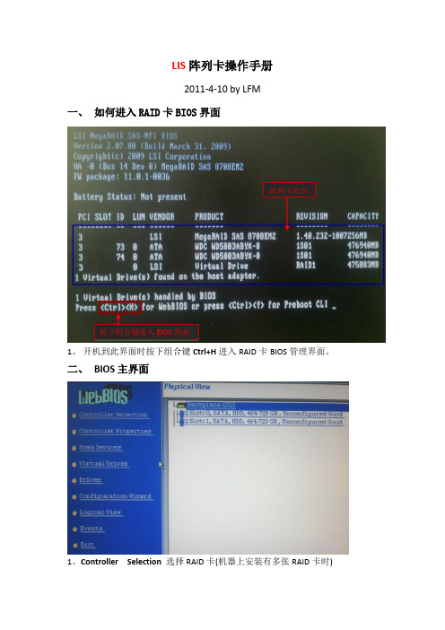
LIS阵列卡操作手册2011-4-10 by LFM一、如何进入RAID卡BIOS界面阵列卡信息按下组合键进入BIOS界面1、开机到此界面时按下组合键Ctrl+H进入RAID卡BIOS管理界面。
二、BIOS主界面1、Controller Selection 选择RAID卡(机器上安装有多张RAID卡时)2、Controller Properties RAID卡属性设置3、Scan Devices 刷新硬盘设备,4、Virtual Drives 虚拟磁盘管理,设置阵列引导顺序-选择要引导的阵列-选择—set boot drive〔currnet=0〕后点GO5、Drives 物理硬盘管理6、Configuration Wizard 创建阵列配置(配置向导)7、Logical View/Physical View查看逻辑/物理磁盘(点击切换)8、Events 事件日志9、Exit 退出三、创建阵列1、查看物理硬盘在界面右面可看到可用于做RAID的硬盘错误!Slot:0——为硬盘的物理位置,在0号端口。
错误!Unconfigured Good-—好的,未配置的硬盘.2、点击“Configuration Wizard”进入创建阵列配置,如图:12错误!Clear Configuration 清除所有的阵列配置信息错误!New Configuration 新建RAID配置(会清除所有的数据,一般只在新机器第一次做阵列时选择)错误!Add Configuration 曾加RAID配置3、一般选择Add Configuration,按Nex t进入下一步:12○,1Manual Configuration 手动配置错误!Automatic Configuration 自动配置3、选Manual Configuration手动配置进入下一步:12错误!在左边“Drives”框中选择要做RAID的磁盘,按住Ctrl键可一次同时几个。
LSI阵列卡配置步骤
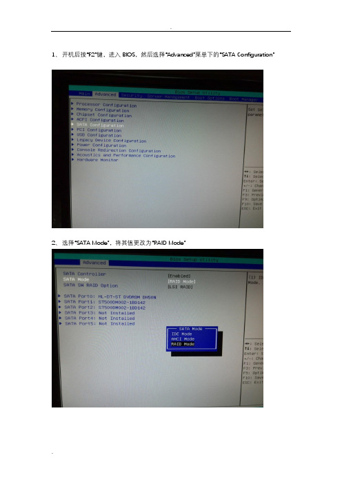
1、开机后按“F2”键,进入BIOS,然后选择“Advanced”菜单下的“SATA Configuration”2、选择“SATA Mode”,将其值更改为“RAID Mode”3、然后选择“SATA SW RAID Option”,将其值更改为“LSI RAID”4、更改完成后,按“F10”保存退出BIOS配置界面。
5、待机器重启后,出现如下提示界面时,按下“Ctrl+M”组合键6、出现LSI阵列配置界面后,选择第一个“Configure”菜单,然后回车。
7、然后选择“New Configuration”菜单,然后回车。
8、然后再选择“Yes”,继续处理。
9、然后在标注为“READY”的Port上按空格键,以选择该端口下的磁盘作为RAID的成员。
不同的机器可能端口号显示不一致,不影响使用。
被选择了的端口显示变成如下这种“ONLINE A00-00”“ONLINE A00-01”10、在磁盘被选择了后,按“F10”,确定适用以上两块磁盘作为RAID磁盘后,出现如下提示11、然后再按“空格”键,将刚刚选择的两块磁盘作为俄日SPAN-1的成员;然后再按“F10”键以配置该RAID。
12、按下“F10”之后,应该出现Virtual Drive 0清单13、然后在VirtualDrive0清单内选择“Accept”,然后按“回车”14、在出现了如下菜单提示时,按下“ESC”键15、最后,出现“Save Configuration?”菜单,选择“Yes”保存配置。
16、最后出现了当前VD0的信息,一直按“ESC”键,直到最后出现一个提示问是否要退出RAID配置界面,选择“Yes”。
17、最后,RAID软件要求按下“Ctrl+Alt+Del”来重启主机,让RAID生效。
18、重启主机后,如果RAID配置成功,应该出现如下提示。
19、本文内配置的RAID为LSI软阵列配置RAID1的步骤,如果需要配置Intel的阵列,请在第3步选择“Intel RAID”,然后在重启主机并出现Intel RAID提示信息时,按下“Ctrl+I”,操作步骤相对简单得多,按提示操作即可。
LSI系列芯片Raid卡配置、管理手册
左侧方框内可以看到所有未使用的硬盘。我们选择全部(也可以逐个选择),然后点击下方的【Add to Array】将其加入到右侧方框内。 点击【Accept DG】,创建磁盘组
点击【Next】下一步 点击【Add to SPAN】,将刚才创建好的磁盘组加入到右侧方框内
点击【Next】下一步 阵列参数配置:第一个参数“Raid Level”选择Raid6,其余保持默认
回到配置页面,点击【Next】下一步 点击【Accept】配置完成!
提示保存,选择【yes】 (依Raid卡型号不同,有些可能没有此功能,如没有请跳过此步)提示SSD缓存,选择【Cancel】
提示初始化,选择【yes】 正在初始化,能看到百分比进度条(速度较快,可能一闪而过)
初始化完成!点击【Home】返回首页
一块硬盘显示红色Offline(或者Failed)
进入WebBIOS主页,发现一块硬盘显示红色Offline状态,同时阵列降级变成了蓝色Degraded状态,此时数据还是可用的,选中红色硬盘进入属性页面。
在属性列表中找到“Media Error”和“Pred Fail Count”两项(如果找不到请点击【Next】翻页),两项都是零,说明硬盘无故障,可以放心使用!
点击【Next】下一步 阵列参数配置:第一个参数“Raid Level”选择Raid10,其余保持默认
最后一个参数“Select Size”输入阵列容量大小,最大值可参考右侧绿字提示(其中R10代表做Raid10的最大容量),完成后点击【Accept】 弹出的任何提示均选择【yes】
回到配置页面,点击【Next】下一步 点击【Accept】配置完成!
提示保存,选择【yes】 (依Raid卡型号不同,有些可能没有此功能,如没有请跳过此步)提示SSD缓存,选择【Cancel】
SAS6068E
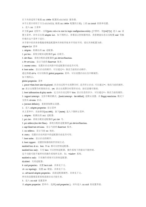
以下内容适用于板载sas 1068e 配置的r515/r525 服务器。
本节主要介绍用于万全r515/r525( 板载sas 1068e 配置的主板) 上的sas irraid 的简单设置。
1、进入sas 主菜单在主板post 过程中,出现[press ctrl-c to start lsi logic configuration utility...]字样时,按[ctrl]+[c] 进入sas 设置主菜单。
回车后出现adapter list,如下图所示。
屏幕显示控制器列表,查看硬盘信息以及配置raid 等操作都在这个菜单下进行。
本手册中的具体参数随着硬盘配置和具体软件版本不同而不同,请以具体配置为准。
adapter list 菜单1. adapter:检测出的sas 适配器。
2. pci bus:系统分配给适配器的pci 总线号。
3. dev/func:系统分配给适配器的pci device/function。
4. fw revision:显示当前的firmware 版本。
5. current status:设置在启动列表中的适配器目前是否可用。
6. boot order:显示启动的顺序,可以通过+/- 修改当前的启动顺序。
通过热键alt+n 可以切换到global properties 菜单,可以设置启动以及中断属性。
如下图所示:global properties 菜单1. pause when boot alert displayed:在启动过程中出现警告时,是否停止启动。
可以通过+/- 修改当前的属性。
no 表示出现警告时继续启动,yes 表示出现警告时暂停启动,按任意键可继续。
2. boot information display mode:定义在启动过程中bios 显示信息的多少。
可以通过+/- 修改当前的属性。
3. support interrupt:支持中断的模式。
[hook interrupt,the default] 是默认设置,在floppy emulation 模式下支持从cd-rom 启动。
m_LSI_SAS_1068E
USER’SGUIDEIntegrated RAIDJ u l y2003Version 1.0 - Preliminary®DB15-000292-00This document is preliminary.As such,it contains data derived from functionalsimulations and performance estimates.LSI Logic has not verified either thefunctional descriptions,or the electrical and mechanical specifications usingproduction parts.This document contains proprietary information of LSI Logic Corporation.Theinformation contained herein is not to be used by or disclosed to third partieswithout the express written permission of an officer of LSI Logic Corporation.LSI Logic products are not intended for use in life-support appliances,devices,or e of any LSI Logic product in such applications without writtenconsent of the appropriate LSI Logic officer is prohibited.Document DB15-000292-00,Version1.0(July2003)This document describes LSI Logic Corporation’s Integrated RAID(IR)softwareproduct and will remain the official reference source for all revisions/releases ofthis product until rescinded by an update.LSI Logic Corporation reserves the right to make changes to any products hereinat any time without notice.LSI Logic does not assume any responsibility orliability arising out of the application or use of any product described herein,except as expressly agreed to in writing by LSI Logic;nor does the purchase oruse of a product from LSI Logic convey a license under any patent rights,copyrights,trademark rights,or any other of the intellectual property rights ofLSI Logic or third parties.Copyright©2003by LSI Logic Corporation.All rights reserved.TRADEMARK ACKNOWLEDGMENTLSI Logic,the LSI Logic logo design,Fusion-MPT,Integrated Mirroring,andIntegrated Striping are trademarks or registered trademarks of LSI LogicCorporation.ARM is a registered trademark of ARM Ltd.,used under license.Windows and Windows NT are registered trademarks of Microsoft Corporation.Linux is a registered trademark of Linus Torvalds.SuSE is a registered trademarkof SuSE Linux AG.RED HA T is a registered trademark of Red Hat,Inc.All otherbrand and product names may be trademarks of their respective companies.KLTo receive product literature,visit us at .For a current list of our distributors,sales offices,and design resourcecenters,view our web page located at/contacts/index.htmliiVersion1.0Copyright©2003by LSI Logic Corporation.All rights reserved.PrefaceThis user’s guide explains how to configure and use the components ofthe LSI Logic Integrated RAID(IR)software product.AudienceThis user’s guide assumes that you have some familiarity with installingand configuring software programs and that you are familiar withcomputer storage devices in general.The people who benefit from thisdocument are:•VARs and OEMs who are evaluating the LSI Logic IR softwarecomponents or who are using the IR software product in theircomputer systems•End users who are using the IR software product to configuremirrored or striped volumes.OrganizationThis document has the following chapters and appendixes:•Chapter1,Introduction to Integrated RAID,provides an overviewof Integrated RAID,its features,and its benefits.•Chapter2,Integrated Mirroring(IM)Overview,This chapterprovides an overview of the LSI Logic Integrated Mirroring™(IM)feature.•Chapter3,Setting Up Integrated Mirroring,describes how to setup Integrated Mirroring(IM)using the BIOS-based configurationutility.•Chapter4,Integrated Striping(IS)Overview,provides an overviewof the LSI Logic Integrated Striping™(IS)feature.Integrated RAID User’s Guide iiiVersion1.0Copyright©2003by LSI Logic Corporation.All rights reserved.•Chapter5,Setting Up Integrated Striping,describes how to set upIntegrated Striping(IS)using the BIOS-based configuration utility.•Chapter6,CIM Solution,describes the Fusion-MPT™CommonInformation Model(CIM)Solution and explains how it is used tomonitor storage components,including mirrored and stripedvolumes,in multiple systems on a network.•Appendix A,Using the DOS-Based Configuration Utility,describes how to set up Integrated Mirroring or Integrated Stripingvolumes using the DOS-based configuration utility(for manufacturinguse only).Related PublicationsLSI Logic DocumentsFusion-MPT Device Management User’s Guide,Version2.0,DB15-000186-02LSI Logic World Wide Web Home PageConventions Used in This ManualThefirst time a word or phrase is defined in this manual,it is italicized.Hexadecimal numbers are indicated by the prefix“0x”—for example,0x32CF.Binary numbers are indicated by the prefix“0b”—for example,0b0011.0010.1100.1111.Revision HistoryRevision Date Remarks6/2003Initial release of document.PreliminaryVersion1.0iv PrefaceVersion1.0Copyright©2003by LSI Logic Corporation.All rights reserved.ContentsChapter1Introduction to Integrated RAID1.1Introduction1-11.2Integrated RAID Benefits and Features1-21.3Using this Manual1-2 Chapter2Integrated Mirroring(IM)Overview2.1Introduction2-12.2Features2-22.3Description2-32.4Integrated Mirroring Firmware2-52.4.1Host Interface2-52.4.2Resynchronization with Concurrent Host I/OOperation2-52.4.3Meta Data Support2-52.4.4Hot Swap2-62.4.5SMART Support2-62.4.6Floating Hot Spare2-62.4.7Media Verification2-72.4.8SCSI ID Assignment2-72.4.9Disk Write Caching2-72.4.10NVSRAM Usage2-72.5Fusion-MPT Support2-82.5.1BIOS ROM2-82.5.2OS Drivers2-8Integrated RAID User’s Guide vVersion1.0Copyright©2003by LSI Logic Corporation.All rights reserved.Chapter3Setting Up Integrated Mirroring3.1IM Configuration Overview3-13.2Configuring IM with the BIOS-Based CU3-23.2.1Quick IM Configuration Procedure3-23.2.2Configuration Screen Overview3-43.2.3Detailed IM Configuration Procedure3-53.2.4Other BIOS-Based CU Screens3-113.3T roubleshooting3-143.3.1RAID Properties Menu Item Disabled3-143.3.2IM Volume Uses Extra SCSI ID3-143.3.3Configuration Utility Disables Selection of Disk3-15 Chapter4Integrated Striping(IS)Overview4.1Introduction4-14.2IS Features4-24.3IS Description4-24.4Integrated Striping Firmware4-44.4.1Host Interface4-44.4.2Meta Data Support4-44.4.3SMART Support4-44.4.4SCSI ID Assignment4-44.4.5Disk Write Caching4-54.5Fusion-MPT Support4-54.5.1BIOS ROM4-54.5.2OS Drivers4-5 Chapter5Setting Up Integrated Striping5.1IS Configuration Overview5-15.2Configuring IS with the BIOS-Based CU5-25.2.1Quick IS Configuration Procedure5-25.2.2Configuration Screen Overview5-35.2.3Detailed IS Configuration Procedure5-45.2.4Other BIOS-Based CU Screens5-95.3T roubleshooting5-11vi ContentsVersion1.0Copyright©2003by LSI Logic Corporation.All rights reserved.5.3.1RAID Properties Menu Item Disabled5-115.3.2Configuration Utility Disables Selection of Disk5-12 Chapter6CIM Solution6.1Description6-16.1.1Features6-26.1.2Installation and System Requirements6-36.2CIM Browser Window Description6-46.2.1Connect Menu Options6-46.2.2Hardware Device T ree Options6-46.3CIM Installation Instructions for Windows6-86.3.1Installing the CIM Solution6-86.3.2Uninstalling the CIM Solution6-86.4CIM Installation Instructions for Linux6-96.4.1Installing the CIM Solution6-96.4.2Uninstalling the CIM Solution6-9 Appendix AUsing the DOS-Based Configuration UtilityA.1Configuration Overview A-1A.2Running the DOS-Based CU A-2A.3Rules for Command Line Options A-3A.4Configuring an IM Volume with the DOS-Based CU A-3A.4.1Command Line Options A-4A.4.2Making Manufacturing Settings Read Only A-7A.4.3IM Parameter Defaults for Fusion-MPT SCSIControllers A-7A.4.4Examples of Command Line Usage A-8A.5Configuring an IS Volume with the DOS-Based CU A-10A.5.1Command Line Options A-10A.5.2Making Manufacturing Settings Read Only A-12A.5.3IS Parameter Defaults for Fusion-MPT SCSI ControllersA-13A.5.4Examples of Command Line Usage A-13Customer FeedbackContents viiVersion1.0Copyright©2003by LSI Logic Corporation.All rights reserved.viii ContentsVersion1.0Copyright©2003by LSI Logic Corporation.All rights reserved.Figures2.1T ypical Mainboard Implementation2-32.2Integrated Mirroring with T wo Disks2-42.3Integrated Mirroring with More than T wo Disks2-43.1Screen Field Definitions3-43.2Main Screen3-53.3Adapter Properties Screen3-63.4RAID Properties Screen:No IM Volume Configured3-73.5RAID Properties Screen:One IM Volume Configured3-103.6Global Properties Screen3-113.7Boot Adapter List Screen3-123.8Device Properties Screen3-134.1Integrated Striping Example4-34.2Integrated Striping-Logical and Physical Views4-35.1Screen Field Definitions5-35.2Main Screen5-45.3Adapter Properties Screen5-55.4RAID Properties Screen:No IS Volume Configured5-65.5RAID Properties Screen:One IS Volume Configured5-85.6Global Properties Screen5-95.7Boot Adapter List Screen5-105.8Device Properties Screen5-116.1Hardware Device T ree Structures6-6ix Version1.0Copyright©2003by LSI Logic Corporation.All rights reserved.xVersion1.0Copyright©2003by LSI Logic Corporation.All rights reserved.Tables6.1Connect Menu Option Description6-46.2Device T ree Description6-7xi Version1.0Copyright©2003by LSI Logic Corporation.All rights reserved.xiiVersion1.0Copyright©2003by LSI Logic Corporation.All rights reserved.Chapter1Introduction to Integrated RAIDThis chapter provides an overview of Integrated RAID,its features,andits benefits.The chapter includes these sections:•Section1.1,“Introduction,”page1-1•Section1.2,“Integrated RAID Benefits and Features,”page1-2•Section1.3,“Using this Manual,”page1-21.1IntroductionThe LSI Logic Integrated RAID solution provides cost benefits for theserver or workstation market where the extra performance,storagecapacity,and/or redundancy of a RAID configuration are required.Thetwo components of Integrated RAID are:•Integrated Mirroring(IM),which provides features of RAID1andRAID1E•Integrated Striping(IS),which provides features of RAID0By simplifying the IM and IS configuration options and by providingfirmware support in its host adapters,LSI Logic can offer the IntegratedRAID solution at a lower cost than a full-blown RAID implementation.LSI Logic CIM interface software is used to continuously monitor IMvolumes and IS volumes and to report status and error conditions as theyarise.IM and IS are supported by different versions of Fusion-MPTfirmware.Therefore,either IM or IS can be implemented on a system with aFusion-MPT based controller,but IM and IS cannot be used concurrentlyon the same system.Integrated RAID User’s Guide1-1Version1.0Copyright©2003by LSI Logic Corporation.All rights reserved.1.2Integrated RAID Benefits and Features•Low cost single-volume RAIDfills the needs of most internal RAIDinstallations•Easy to use-installation and configuration are not complex•System can boot from an IM or IS volume•No special OS-specific software required•High reliability and data integrity–Non-volatile write journaling–Physical disks not visible to OS or to application software•Low host CPU and PCI bus utilization•Fusion-MPT architecture provides processing power–160MHz ARM966processors provide maximum processingcapacity–Shared memory architecture minimizes external memoryrequests–Functionality is contained in device hardware andfirmware1.3Using this Manual•Chapters2and3of this User’s Guide explain how to configure anIntegrated Mirroring(IM)volume.•Chapters4and5explain how to configure an Integrated Striping(IS)volume.•Chapter6explains how to install CIM and how to use it to monitorIM and IS volumes.•Appendix A explains how to use the DOS-based configuration utilityto configure IM and IS volumes in the manufacturing environment.1-2Introduction to Integrated RAIDVersion1.0Copyright©2003by LSI Logic Corporation.All rights reserved.Chapter2Integrated Mirroring(IM)OverviewThis chapter provides an overview of the LSI Logic Integrated Mirroring(IM)feature and includes these sections:•Section2.1,“Introduction,”page2-1•Section2.2,“Features,”page2-2•Section2.3,“Description,”page2-3•Section2.4,“Integrated Mirroring Firmware,”page2-5•Section2.5,“Fusion-MPT Support,”page2-82.1IntroductionAs a result of the shift towards Network Attached Storage(NAS),ISPsneed a cost effective,fault-tolerant solution to protect the operatingsystems on small form factor,high-density,rack-mountable servers.TheLSI Logic Integrated Mirroring(IM)feature provides data protection forthe system boot volume to safeguard critical information such as theoperating system on servers and high performance workstations.Thisnew Integrated Mirroring feature gives customers a robust,high-performance,fault-tolerant solution that is less expensive than adedicated RAID controller.The IM feature provides simultaneous mirroring on configurations of twoto six disk disks,to assure fault tolerant,high availability data.If a diskfails,the hot swap capability allows the system to be easily restored bysimply swapping disks.The system then automatically re-mirrors theswapped disk.Additionally,the hot spare feature keeps one disk readyto automatically replace a failed disk in the volume,making the systemeven more fault-tolerant.Integrated RAID User’s Guide2-1Version1.0Copyright©2003by LSI Logic Corporation.All rights reserved.The IM feature uses the same device drivers as the standard Fusion-MPT based controllers,providing seamless and transparent faulttolerance.This eliminates the need for complex backup software orexpensive RAID hardware.The IM feature operates independently fromthe operating system,in order to conserve system resources.The BIOS-based configuration utility makes it easy to configure a mirrored volume.The IM feature is currently available as an optional component of the newFusion-MPT architecture on all LSI Logic Ultra320SCSI integrated I/Ocontroller products.2.2FeaturesThis section lists the key features of Integrated Mirroring.•Supports configurations of two to six mirrored disks on the samechannel•Mirrored volume runs in optimal mode or degraded mode(that is,ifone mirrored disk fails)•(Optional)Supports configuration of a hot spare•Hot swap capability•Presents a single virtual drive to the OS•Support for disks of different types and capacities•Fusion-MPT architecture•Easy-to-use BIOS-based configuration utility(and DOS-basedconfiguration utility for manufacturing use only)•Support for greater volume capacity by integrating more disks•Error notification–OS-specific event log–Errors displayed on CIM browser•SAF-TE drive status LED support for Integrated Mirroring disks•Write journaling,which allows automatic synchronization ofpotentially inconsistent data after unexpected power-down situations •Meta data used to store volume configuration on mirrored disks2-2Integrated Mirroring(IM)OverviewVersion1.0Copyright©2003by LSI Logic Corporation.All rights reserved.Description2-3Version 1.0Copyright ©2003by LSI Logic Corporation.All rights reserved.•Automatic background resynchronization while host I/Os continue •Media verification2.3DescriptionThe LSI Logic Integrated Mirroring (IM)feature provides mirroring for the boot volume,as shown in Figure 2.1.This is accomplished through the firmware of an LSI Logic controller that supports the standard Fusion-MPT interface.The runtime mirroring of the boot disk is transparent to the BIOS,drivers,and operating system.Host-based status software monitors the state of the mirrored disks and reports any error conditions.In Figure 2.1the system is configured with a second disk as a mirror of the first (primary)disk.Figure 2.1Typical Mainboard ImplementationFigure 2.2shows the logical view and physical view of the mirroring configuration when there are two disks in the mirrored volume.Two Disk DrivesOS MirroredOSNVSRAMEEPROM(For Configuration)(For Write Journaling)LSI LogicInternalMemory ExternalBusSCSI SCSI Fusion-MPTController2-4Integrated Mirroring (IM)OverviewVersion 1.0Copyright ©2003by LSI Logic Corporation.All rights reserved.Figure 2.2Integrated Mirroring with Two Disks Mirroring can also be configured with up to 6mirrored disks,or 5mirrored disks and a hot spare.Figure 2.3shows the logical view and physical view of the mirroring configuration with more than two disks in the mirrored volume.Each “mirrored stripe”is written to a disk and is mirrored to an “adjacent”disk.This is commonly referred to as RAID 1E.Figure 2.3Integrated Mirroring with More than Two DisksLSI Logic provides the BIOS-based configuration utility to enable the user to configure the mirroring attributes during initial setup and toreconfigure them in response to hardware failures or changes in the LBA 1LBA 2LBA 3LBA N +Logical View Physical ViewLBA 1’LBA 2’LBA 3’LBA N’LBA 1LBA 2LBA 3LBA N Mirrored Stripe 1Mirrored Stripe 2Mirrored Stripe 3Mirrored Stripe n++Logical ViewPhysical View Mirrored Stripe 1Mirrored Stripe 3’Mirrored Stripe 4Mirrored Stripe n-2Mirrored Stripe 6’Mirrored Stripe n’Mirrored Stripe 2Mirrored Stripe 1’Mirrored Stripe 5Mirrored Stripe n-1Mirrored Stripe 4’Mirrored Stripe (n-2)’Mirrored Stripe 3Mirrored Stripe 2’Mirrored Stripe 6Mirrored Stripe n Mirrored Stripe 5’Mirrored Stripe (n-1)’Mirrored Stripe 6Mirrored Stripe 5Mirrored Stripe 4environment.(A DOS-based configuration utility is also provided formanufacturing use only.)2.4Integrated Mirroring FirmwareThis section describes features of the LSI Logic Integrated Mirroring(IM)firmware.2.4.1Host InterfaceThe IM host interface uses the“Message Passing Interface”as describedin the Fusion-MPT specification,including Integrated Mirroring of SCSIhost adapters.Through the Fusion-MPT interface,the host OS hasaccess to the logical IM drive as well as the physical disks.This allowssupport for domain validation and Ultra320SCSI expander configuration.2.4.2Resynchronization with Concurrent Host I/O OperationThe IMfirmware uses queue tagged I/Os to allow SCSI I/Os to continueon the IM volume while the volume is being re-synchronized in thebackground.The host driver may optionally suspend theresynchronization operation while performing domain validation or whileconfiguring Ultra320SCSI expanders.Resynchronization is attemptedafter thefirmware has been reset,or after a“hot swap”has occurred toone of the physical IM disks.The IM volume can be partially resynchronized,if the logging informationin NVSRAM indicates that this is necessary.It usually takes less than asecond for thefirmware to complete a partial resynchronization.Like fullsynchronization,partial resynchronization is performed in thebackground.2.4.3Meta Data SupportThefirmware supports Meta data describing the IM logical driveconfiguration stored on each member disk.When thefirmware isinitialized,each member disk is queried to read the stored Meta data forconsistency checking.The usable disk space for each IM member diskis adjusted down to leave room for this data.Integrated Mirroring Firmware2-5Version1.0Copyright©2003by LSI Logic Corporation.All rights reserved.2.4.4Hot SwapThe IMfirmware supports hot swapping.The hot-swapped disk isautomatically resynchronized in the background,without any host or userintervention.The hot-swapped disk must be at the same physical SCSIID as one of the physical disks configured in the IM volume.Thefirmwaredetects“Hot Swap”removal and disk insertion.Following a“hot swap”event,thefirmware readies the new physical diskby spinning it up and verifying that it has enough capacity for the IMvolume.The IMfirmware resynchronizes all hot-swapped disks that havebeen removed,even if the same disk is re-inserted.In a two-diskmirrored volume,the IMfirmware marks the hot-swapped disk as thesecondary disk and marks the other mirrored disk as the primary disk.Thefirmware resynchronizes all data from the primary disk onto the newsecondary disk.2.4.5SMART SupportThe IMfirmware enables Mode6SMART on the IM member disks.Mode6SMART requires each physical disk to be polled once perminute.If a SMART ASC/ASCQ code is detected on a physical IM disk,thefirmware processes the SMART data,and the last received SMARTASC/ASCQ is stored in non-volatile memory.The IM volume does notsupport SMART directly,since it is just a logical representation of thephysical disks in the volume.2.4.6Floating Hot SpareOne disk can be configured as thefloating hot spare disk.If the IMfirmware fails one of the mirrored disks,thefirmware automaticallyreplaces it with the hot spare disk.The IMfirmware then resynchronizesthe mirrored data.The SCSI ID of the failed disk is periodically polled todetermine if the disk has been replaced.If so,thefirmware automaticallyestablishes that disk as the new“floating hot spare.”2-6Integrated Mirroring(IM)OverviewVersion1.0Copyright©2003by LSI Logic Corporation.All rights reserved.2.4.7Media VerificationThe IMfirmware supports a background media verification feature thatruns once per minute when the IM volume is in optimal mode.The mediaverification feature issues a SCSI Verify command to a segment of thedisk.If the command fails for any reason,the other disk’s data for thissegment is read and written to the failing disk in an attempt to refreshthe data.The current Media Verification Logical Block Address is writtento non-volatile memory occasionally to allow Media Verification tocontinue approximately where it left off prior to a power-cycle.2.4.8SCSI ID AssignmentA single logical drive is presented as the combination of a set of physicalmember disks.Each individual member disk is hidden and returns a“selection timeout”when accessed.The SCSI Target ID of the IM logicaldrive is assigned when the logical drive is created.The lowest SCSI IDof the selected disks is used.2.4.9Disk Write CachingThe IMfirmware disables disk write caching.This is done to increasedata integrity,so that the disk write log stored in NVSRAM is alwaysvalid.If disk write caching were enabled(not recommended),the diskwrite log could be invalid.2.4.10NVSRAM UsageIMfirmware requires a32Kbyte NVSRAM in order to perform writejournaling.Write journaling is used to verify that the mirrored disks in theIM volume are synchronized with each other.The NVSRAM also storesadditional code and data used for error and exception handling,and itstores IM configuration information during serial EEPROM updates.Thedisk write log uses approximately4Kbytes of the NVSRAM.Integrated Mirroring Firmware2-7Version1.0Copyright©2003by LSI Logic Corporation.All rights reserved.2.5Fusion-MPT SupportThe LSI Logic Fusion-MPT architecture provides the interface to theSCSI chip/firmware to allow Integrated Mirroring.2.5.1BIOS ROMThe BIOS uses the Fusion-MPT interface to communicate to the SCSIchip/firmware to allow Integrated Mirroring.This includes reading theFusion-MPT configuration to gain access to the SCSI parameters thatare used to define behavior between the adapter and its devices.2.5.2OS DriversThe Fusion-MPT drivers for all supported operating systems implementthe Fusion-MPT interface to communicate with the SCSI chip/firmware.To allow Integrated Mirroring,the host OS driver implements domainvalidation and supports Ultra320expander configurations.2-8Integrated Mirroring(IM)OverviewVersion1.0Copyright©2003by LSI Logic Corporation.All rights reserved.Chapter3Setting Up IntegratedMirroringThis chapter describes how to set up Integrated Mirroring(IM)using theBIOS-based configuration utility(CU).The chapter includes these topics:•Section3.1,“IM Configuration Overview”•Section3.2,“Configuring IM with the BIOS-Based CU”•Section3.3,“T roubleshooting,”page3-143.1IM Configuration OverviewThe following constraints were made in order to simplify the IMconfiguration.•The BIOS-based CU allows you to create one mirrored volume perFusion-MPT controller.•The mirrored volume can have two to six disks,or two tofive disksif an optional hot spare disk is used.•Disks in a mirrored volume must be connected to the same channelof the same Fusion-MPT controller,and the controller must be in theBIOS boot order.•Disks in an IM volume must be non-removable,single-LUN disks thatsupport512-byte sectors,wide synchronous transfers,Qtag’d I/Os,and a unit serial number.The disks must support SMART,and theymust be minimally compliant with the SCSI-2standard.•Disks of different size are allowed in mirrored volumes,but thesmallest disk determines the“logical”size of each disk in the volume.The excess space of larger member disks is not used.Integrated RAID User’s Guide3-1Version1.0Copyright©2003by LSI Logic Corporation.All rights reserved.3.2Configuring IM with the BIOS-Based CUThe BIOS-based configuration utility(CU)is part of the Fusion-MPTBIOS.When the BIOS loads during boot and you see the message aboutthe LSI Logic Configuration Utility,press Ctrl-c to start the utility.Afteryou do this,the message changes to:“Please wait, invoking LSI Logic Configuration Utility...”3.2.1Quick IM Configuration ProcedureFollow the steps below to configure an Integrated Mirroring(IM)volumewith the BIOS-based CU.For a more complete explanation of thisprocedure,including detailed descriptions of the configuration screens,see Section3.2.3,“Detailed IM Configuration Procedure,”page3-5.The configuration procedure assumes that the system already has therequired SCSI controller(s)and disks.Y ou can configure one IM volumeper Fusion-MPT controller.1.On the Main menu screen of the BIOS-based CU,use the arrow keysto select an adapter.2.Press Enter to go to the Adapter Properties screen.3.On the Adapter Properties screen,use the arrow keys to select RAIDProperties on the screen.4.Press Enter to go to the RAID Properties screen.Continue withstep5to configure a two-disk mirrored volume.Skip to step6toconfigure a mirrored volume with three to six disks.5.To configure a two-disk mirrored volume,with an optional hot sparedisk:a.In the RAID Properties screen,use the arrow keys to select theprimary disk for the IM volume(the disk with the data you wantto mirror).e the arrow keys to move to the Array Disk column for thisdisk,and use the+and-keys to select Yes as the value.c.When the“Keep Data/Erase Disk”message appears,press F3to keep the data that is currently on this disk.The value in theArray Disk column changes to Primary.3-2Setting Up Integrated MirroringVersion1.0Copyright©2003by LSI Logic Corporation.All rights reserved.。
- 1、下载文档前请自行甄别文档内容的完整性,平台不提供额外的编辑、内容补充、找答案等附加服务。
- 2、"仅部分预览"的文档,不可在线预览部分如存在完整性等问题,可反馈申请退款(可完整预览的文档不适用该条件!)。
- 3、如文档侵犯您的权益,请联系客服反馈,我们会尽快为您处理(人工客服工作时间:9:00-18:30)。
LSI SAS 1068E RAID配置说明
一:开机进入硬件检测画面,当看到检测LSI SAS 1068E 芯片完后按住CTRL+C进入RAID配置界面,如下图:
此画面可以看到SAS 控制芯片为1068E ,回车进入下一个配置界面,如下图:
用键盘上左右方向键选择选项,此时我们选择到“RAID Properties”选项,回车进入到RAID 配置界面,如下图:
如上图所示:第一选项为创建RAID1镜像(Creat IM volume).第二选项为创建RAID1E(Creat IME volume)第三选项为创建RAID0(Creat IS volume).选择你所需要创建的RAID模式,按回车键进入下一个配置界面,如下图:
用键盘左右方向键选择到“RAID Disk” 选项按空格键选择硬盘,选择完硬盘后按C键创建RAID。
创建完后进入下一界面,如下图:
此时选择保存退出。
到此RAID创建完毕。
