思科3560配置手册
思科3560交换机配置实例

!
interface GigabitEthernet0/6
switchport access vlan 4
switchport mode access
!
interface GigabitEthernet0/7
switchport access vlan 5
ip routing
!
!
!
!
no file verify auto
spanning-tree mode pvst
spanning-tree extend system-id
!
vlan internal allocation policy ascending
!
interface GigabitEthernet0/1
switchport mode access
!
interface GigabitEthernet0/8
switchport access vlan 5
switchport mode access
!
interface GigabitEthernet0/9
switchport access vlan 5
switchport mode access
!
interface GigabitEthernet0/24
no switchport
ip address 172.16.9.1 255.255.255.0
!
interface GigabitEthernet0/25
!
interface GigabitEthernet0/26
switchport mode access
cisco8021x配置3560

cisco8021x配置3560交换机为思科3560(支持三层交换,静态路由)使用缺省VLAN------VLAN1ClientA和ClientB为测试客户端ClientA=>192.168.100.100ClientB=>192.168.100.200Core Server为核心服务器(安装SP3)Core Server=>192.168.100.20IAS为认证服务器(装proxy)IAS=>192.168.100.10认证服务器的交换机端口192.168.100.11.进入配置模式Switch>en2.在交换机上建立VLAN在此可以设置自己的VLAN(参见注意3。
本例中将使用缺省VLAN1)3.设置VLAN 1的IP地址Switch#conf tSwitch(config)#int vlan 1Switch(config-if)#ip add 192.168.100.1 255.255.255.0Switch(config-if)#no shutSwitch(config)#exit4.启用AAA并创建802.1x端口认证方式列表Switch(config)#aaa newSwitch(config)#aaa authentication dot1x default group radius5.为交换机全局启用802.1x端口认证Switch(config)#dot1x system-auth-control6.设置主认证RADIUS(proxy)服务器的IP地址及认证交互报文时的通信密码。
Switch(config)#radius-server host 192.168.100.10 auth-port 4001 key scab7.进入f0/1端口设置(每个端口都要设置,7、8、9、10联动)Switch(config)#int f0/18.指定f0/1端口为接入端口(每个端口都要设置,7、8、9、10联动)Switch(config-if)#switchport mode access9.在f0/1端口上启用802.1x(每个端口都要设置,7、8、9、10联动)Switch(config-if)#dot1x port-control auto10.设定802.1x的传送超时定时器(每个端口都要设置,7、8、9、10联动)Switch(config-if)#dot1x timeout tx-period 5Switch(config-if)#exitSwitch(config)#exit11.备份设置Switch#copy run start注意:1、要将核心服务器、PROXY和RADIUS服务器的在交换机上的联接端口设置成接入端口,参照上面第七、八项设置。
思科3560 配置命令
switch> 命令行模式;config#特权模式一、配置交换机vlan模式;有两种方式第一种:config#vlan ID 这里的ID是需要你个人给要划分的vlan起的编号config-if#name 名字switch#show vlan brief 查看vlan 用来检验是否配置成功第二种:switch#vlan database 交换机的vlan配置状态switch(vlan)#vlan ID name 名字配置vlan 并且分配相应的名字二、3560上开启路由功能配置switch(config)#ip routingswitch(config)#ip route ipaddress net-hop 配置路由(静态)switch(config)#ip default-gateway ipaddress 配置网关三、开启聚合链路配置#conf tSW(config)#interface range f1/1 - 2SW(config-if)#channel-group 1 mode desirable/onSW(config-if)#swithportSW(config-if)#switchport mode trunkSW(config-if)#switchport trunk encap dot1q四、启动telnet管理模式switch(config)#line vty 0 4switch(config-line)#password 密码switch(config-line)#login五、开启cisco日志功能switch(config)#logging onswitch(config)#logging trap 信息switch(config)#logging host 你的IP地址switch(config)#logging facility 你选着的信息配置3550作为dhcp服务器六、配置cisco启动dhcp功能配置地址池switch(config)ip dhcp pool 名字switch(config-pool)network maskswitch(config-pool)dns-serverswitch(config-pool)default-router 网关设置dhcp保留不分配的地址switch(config)ip dhcp excluded-address 地址地址第一步;从起交换机第二步;配置1)按下MODE键后给3560加电。
Cisco Catalyst 3560-E系列交换机 说明书

• LACP 让 用 户 能 够 利 用 符 合 IEEE 802.3ad 的 设 备 创 建 以 太 网 通 道 。 这 种 功 能 类 似 于 思 科
EtherChannel技术和PAgP。
• 如果错误地接上了不正确的电缆类型(交叉或者直通),自动MDIX(依赖于介质的接口交叉)能
Cisco Catalyst 3560-E系列的主要特性
• Cisco TwinGig转换器模块,将上行链路从千兆以太网移植到万兆以太网 • PoE配置,为所有48个端口提供了15.4W PoE • 模块化电源,可带外部可用备份电源 • 在硬件中提供组播路由、IPv6路由和访问控制列表 • 带外以太网管理端口,以及RS-232控制台端口
1
产品简介
Cisco Catalyst 3560-E软件
Cisco Catalyst 3560-E系列配备IP Base或IP Services特性集。IP Base特性集包括高级服务质量 ( QoS ) 、 限 速 、 访 问 控 制 列 表 ( ACL ) 以 及 基 本 的 静 态 和 路 由 信 息 协 议 ( RIP ) 路 由 功 能 。 IP Services特性集则提供一组更加丰富的企业级功能,包括先进的、基于硬件的IP单播和组播路由 (EIGRP、OSPF、BGP、PIM等)。此外,它还提供了一个Advanced IP Services特性集支持IPv6路 由。 通过Cisco IOS® 软件激活功能,客户能够透明地升级Cisco Catalyst 3560-E系列交换机中的软件特性 集。软件激活能够授权和支持Cisco IOS软件特性集。交换机中包含一个特殊的文件,称之为许可证 文件,当交换机启动时Cisco IOS软件将对其进行检查。Cisco IOS软件能根据许可证的类型,激活相 应的特性集。许可证类型能够改变或升级,以激活不同的特性集。
cisco3560 3层交换机和路由器连接,交换机如何配置

如图。
pc0 属于vlan2,pc1属于vlan3,pc0 ip 192.168.0.10 /24 192.168.0.254 pc1 ip 1 0.139.168.10 /21 10.139.168.254 。
所有交换机的管理vlan是vlan4 192.168.1.x/24 。
要求pc0、pc1可以telnet 到交换机,和路由器 R1 ,交换机之间可以互ping通,pc 0和pc1可以ping通pc3。
pc0、pc1、可以互ping通。
3层交换机和路由器R1如何配置,主要是3层交换机如何配置,我已经在交换机的端口配置好了ip 。
路由器之间的ip 1 0.1.1.0/24 也已经配置好。
麻烦高后帮忙配置一下3层交换机和路由器。
谢谢。
分享到:2012-11-21 18:00提问者采纳这种配置我郁闷!我直接打命令看看能不能解决。
同时覆盖你一些配置吧!三层交换机3560enableconfigure terminalinterface range fastethernet0/1 -2switchport trunk encapsulation dot1qswitchport mode trunkexit这个时候,三层交换机接下面的二层交换机都为中继链路了(trunk),同时需要配置vtp,让各个交换机的vlan信息同步,如下配置:三层交换:enableconfigure terminalvtp domain netvtp mode server两个二层交换机都要配:enableconfigure terminalvtp domain netvtp mode client然后在三层交换上配置vlanenablevlan databasevlan 2vlan 3vlan 4exitconfigure terminalinterface vlan 2ip address 192.168.0.254 255.255.255.0exitinterface vlan 3ip address 10.139.168.254 255.255.248.0exitinterface vlan 4ip address 192.168.1.254 255.255.255.0然后在第一个二层交换机上将PC划分相应的vlan当中。
CISCO CATALYST 3560-C 和 2960-C 系列紧凑型交换机 产品手册
CISCO CATALYST 3560-C 和 2960-C系列紧凑型交换机Cisco ® Catalyst ® 3560-C 和 2960-C 系列紧凑型交换机是小尺寸快速以太网和千兆位以太网交换机,专为在配线柜之外进行部署而设计。
通过使用这两款产品,企业级和商用客户可在办公室工作空间、微型分支机构、教室、游轮以及其它配线受限的环境中带来高级安全服务、统一通信、无线、IP 视频摄像头以及其它应用。
无边界网络是思科的下一代架构,可提供全新的工作空间体验,能够以安全、可靠、透明的方式,使用任何设备将任何人在任何场所连接到任何资源。
思科无边界网络架构通过提供更加接近员工和客户的交互而解决了主要的 IT 和业务挑战,有助于创造真正的无边界体验。
在交换方面的创新有助于组织交付简便的操作、绿色效率、安全性以及性能,从而加速 IT 部门在网络上交付和扩展这些服务的方式。
图 2 阐述了思科无边界网络的优势。
图 1. Cisco Catalyst 3560-C 和 2960-C 系列紧凑型交换机PoE 转呈。
一项创新特性,业内首先实现将来自紧凑型交换机的电力传递给终端设备。
• 基于媒体访问控制安全 (MACsec) 硬件的加密。
• 以太网供电增强版 (PoE+),最高可达每端口 30 W 。
• USB 和 10/100 管理端口,可进行文件备份、分发和简单的操作。
• 增强的终身有限硬件保修 (E-LLW),包含下一工作日 (NBD) 高级硬件更换以及 90 天思科技术协助中心 (TAC) 访• 问支持。
思科无边界网络和访问交换Cisco Catalyst 3560-C 和 2960-C 系列紧凑型交换机如图 1 中所示。
Cisco Catalyst 3560-C 和 2960-C 系列的优势包括:表 1 显示了 Cisco Catalyst 3560-C 和 2960-C 系列紧凑型产品的配置信息。
Cisco 3560 Qos限速配置
Cisco 3560 Qos限速配置引用整理一、网络说明user1_PC1接在Cisco3550 F0/1上,速率为1M;ip_add 192.168.1.1/24user2_PC2接在Cisco3550 F0/2上,速率为2M;ip_add 192.168.2.1/24Cisco3560的G0/1为出口,或级联端口。
二、详细配置过程注:每个接口每个方向只支持一个策略;一个策略可以用于多个接口。
因此所有PC的下载速率的限制都应该定义在同一个策略(在本例子当中为policy-map user-down),而PC不同速率的区分是在Class-map分别定义。
1、在交换机上启动QOSSwitch(config)#mls qos //在交换机上启动QOS2、分别定义PC1(192.168.1.1)和PC2(192.168.2.1)访问控制列表Switch(config)#access-list 1 permit 192.168.1.0 0.0.0.255 //控制pc1上行流量Switch(config)#access-list 101 permit any 192.168.1.0 0.0.0.255 //控制pc1下行流量Switch(config)#access-list 2 permit 192.168.1.2 0 0.0.0.255 //控制pc2上行流量Switch(config)#access-list 102 permit any 192.168.2.1 0.0.0.255 //控制pc2下行流量3、定义类,并和上面定义的访问控制列表绑定Switch(config)# class-map user1-up //定义PC1上行的类,并绑定访问列表1Switch(config-cmap)# match access-group 1Switch(config-cmap)# exitSwitch(config)# class-map user2-upSwitch(config-cmap)# match access-group 2 //定义PC2上行的类,并绑定访问列表2Switch(config-cmap)# exitSwitch(config)# class-map user1-downSwitch(config-cmap)# match access-group 101 //定义PC1下行的类,并绑定访问列表101Switch(config-cmap)# exitSwitch(config)# class-map user2-downSwitch(config-cmap)# match access-group 102 //定义PC2下行的类,并绑定访问列表102Switch(config-cmap)# exit4、定义策略,把上面定义的类绑定到该策略Switch(config)# policy-map user1-up //定义PC1上行的速率为1M,超过的丢弃Switch(config-pmap)# class user1-upSwitch(config-pmap-c)# trust dscpSwitch(config-pmap-c)# police 1000000 1000000 exceed-action dropSwitch(config)# policy-map user2-up //定义PC2上行的速率为2M ,超过丢弃Switch(config-pmap)# class user2-upSwitch(config-pmap-c)# trust dscpSwitch(config-pmap-c)# police 2000000 2000000 exceed-action drop Switch(config)# policy-map user-downSwitch(config-pmap)# class user1-downSwitch(config-pmap-c)# trust dscpSwitch(config-pmap-c)# police 1000000 1000000 exceed-action drop Switch(config-pmap-c)# exitSwitch(config-pmap)# class user2-downSwitch(config-pmap-c)# trust dscpSwitch(config-pmap-c)# police 2000000 2000000 exceed-action drop Switch(config-pmap-c)# exit5、在接口上运用策略Switch(config)# interface f0/1Switch(config-if)# service-policy input user1-upSwitch(config)# interface f0/2Switch(config-if)# service-policy input user2-upSwitch(config)# interface g0/1Switch(config-if)# service-policy input user-downCisco 3560 Qos限速配置范例分析一、网络说明user1_PC1接在Cisco3560 F0/1上,速率为1M;ip_add 192.168.1.1/24user2_PC2接在Cisco3560 F0/2上,速率为2M;ip_add 192.168.2.1/24Cisco3560的G0/1为出口,或级联端口。
cisco3560配置手册

3层交换机:管理ip:192.168.1.2 上门连路由器ip:192.168.1.5分2个段:Vlan1 192.168.1.0 255.255.255.0 网关192.168.1.2Vlan5 172.16.5.0 255.255.254.0 网关172.16.5.1键入3560设备管理IP地址Switch>enableSwitch#conf tSwitch(config)# interface vlan 1Switch(config-if)#ip address 192.168.1.253 255.255.255.0 --这里应该用192.168.1.x的地址Switch(config-if)#no shutdownSwitch(config-if)#exitSwitch(config)#line vty 0 4Switch(config-line)#loginSwitch(config-line)#password ciscoSwitch# configure terminalSwitch(config)# ip routingSwitch(config)#ip route 0.0.0.0 0.0.0.0 192.168.1.5 添加到router的默认路由第一步:创建VLAN:Switch>enSwitch#Vlan DatabaseSwitch(Vlan)>Vlan 5 Name vlan5exit第二步:设置VLAN IP地址:Switch#Config TSwitch(Config)>Int Vlan 5Switch(Config-vlan)Ip Address 172.16.5.1 255.255.255.0Switch(Config-vlan)No Shut第三步:设置端口全局参数Switch(Config)Interface Range Fa 0/1 – 12 (1-12当trunk口,用来级联其他交换机)Switch(Config-if-range)Switchport Mode TRUNKSwitch(Config-if-range) switchport trunk encapsulation dot1qEXITSwitch(Config)Interface Range Fa 0/13 – 24 (13-24当访问口用)Switch(Config-if-range)Switchport Mode AccessSwitch(Config-if-range)Spanning-tree Portfast第四步:将端口添加到VLAN5,20-24添加到VLAN5(12-19不添是在vlan1吗?对)Switch(Config)Interface Range Fa 0/20 - 24Switch(Config-if-range)Switchport Access Vlan 5将3550作为DHCP服务器/*VLAN 1和5可用地址池和相应参数的配置, VLAN1和5要设几个地址池*/ 各设一个Switch(Config)Ip Dhcp Pool Test01/*设置可分配的子网*/Switch(Config-pool)Network 192.168.1.0 255.255.255.0/*设置DNS服务器*/Switch(Config-pool)Dns-server 202.103.224.68/*设置该子网的网关*/Switch(Config-pool)Default-router 192.168.1.2Switch(Config)Ip Dhcp Pool Test05/*设置可分配的子网*/Switch(Config-pool)Network 172.16.5.0 255.255.254.0 (这个段给他510台机器使用)/*设置DNS服务器*/Switch(Config-pool)Dns-server 202.103.224.68 (设为电信dns 有问题吗?没问题)/*设置该子网的网关*/Switch(Config-pool)Default-router 172.16.5.1第5步:设置DHCP保留不分配的地址Switch(Config)Ip Dhcp Excluded-address 192.168.1.1 192.168.1.80Switch(Config)Ip Dhcp Excluded-address 192.168.1.121Switch(Config)Ip Dhcp Excluded-address 192.168.1.250 192.168.1.254(VLAN1只分配81到120的ip)第6步:启用路由/*路由启用后,各VLAN间主机可互相访问*/Switch(Config)Ip Routing第7步:配置访问控制列表Switch(Config)access-list 105 permit ip 172.16.5.0 0.0.1.255 any (any=0.0.0.0. 255.255.255.255吗)(要允许172.16这个段上网,需要设这个吗)不用Switch(Config)access-list 105 permit ip 172.16.5.0 0.0.1.255 192.168.1.2 0.0.0.0(允许访问路由器)Switch(Config)access-list 105 permit udp any any eq bootpcSwitch(Config)access-list 105 permit udp any any eq tftp第7,8步可以省略第8步:应用访问控制列表/*将访问控制列表应用到VLAN 5Switch(Config)Int Vlan 5Switch(Config-vlan)ip access-group 105 out第9步:结束并保存配置Switch(Config-vlan)EndSwitch#wr。
Cisco 3560 系列简单三层划分 配置

Cisco 3560 系列简单三层划分配置三层交换机具备网络层的功能,实现VLAN 相互访问的原理是:利用三层交换机的路由功能,通过识别数据包的IP地址,查找路由表进行选路转发,三层交换机利用直连路由可以实现不同VLAN 之间的相互访问。
三层交换机给接口配置IP 地址。
采用SVI(交换虚拟接口)的方式实现VLAN 间互连。
SVI是指为交换机中的VLAN 创建虚拟接口,并且配置IP地址。
实现目标:PC3能访问PC1和PC2, 但PC1不能和PC2/PC3互通 PC2不能和PC1/PC3互通。
\一、首先我们配置PC上的IP和GateWay:PC1IP: 192.168.1.2Submark: 255.255.255.0Gateway: 192.168.1.1PC2IP: 192.168.2.2Submark: 255.255.255.0Gateway: 192.168.2.1PC3IP: 192.168.1.3Submark: 255.255.255.0Gateway: 192.168.1.1二、其次进行对Cisco2950进行vlan划分:Switch1:Switch>en --进入特权Switch#conf t --全局配置Enter configuration commands, one per line. End with CNTL/Z.Switch(config)#vlan 2 --创建vlan 2 使用默认vlan名Switch(config-vlan)#exit --退出vlan 2 配置操作Switch(config)#vlan 3 --创建vlan 3Switch(config-vlan)#exit -- 退出vlan 3 配置操作Switch(config)#int fa0/2 --配置交换机2口Switch(config-if)#switch access vlan 2 设置交换机2口为vlan 2 Switch(config-if)#exit --退出2口操作Switch(config)#int fa0/3 --配置3口Switch(config-if)#switch acces vlan 3 --设置交换机3口为 vlan 3 Switch(config-if)#exit --退出3口配置操作。
cisco_3560配置手册
三层交换机配置与管理一、曰常管理命令二、密码恢复三、VLAN配置四、SPAN监听配置五、DHCP服务配置1. 在上配置DHCP服务2. 配置作为DHCP中继代理六、流量控制七、策略路由一、曰常管理命令l clear arp-cache清除ARP缓存l arp 192.168.100.22 000a.eb22.c1b5 arpa 绑定MAC和IPl sh ip accounting output-packets显示统计信息(当然需要配置统计功能如:ip accounting-transits 3200)l 通过IP追查交换机端口:CiscoWorks 2000 LMS网管软件的User tracking可以追查一个IP地址对应的端口。
sh mac-address-table address 00e0.9102.afd0 显示这个MAC地址在哪个接口出来的;sh mac-address-table interface Fa0/20显示20端口上的MAC地址,如果只有一个,则可能连接一个电脑,如果有很多个条目,则可以连接一个交换机。
sh cdp entry *显示邻居信息;二、密码恢复下面步骤也适用于Cisco 层 2 系列的交换机比如Catalyst 2900/3500XL,2940,2950/2955和层3 系列的比如Catalyst 3550 的密码恢复.通过终端或带有仿真终端程序(比如Hyper Terminal)的PC,连接到交换机的console 对于Catalyst 2900/3500XL 拔下交换机的电源线,然后按住交换机的Mode 按钮,再重新插上交换机的电源线.直到端口Port 1x 的LED 熄灭之后释放Mode 按钮.Catalyst 2940/2950L 拔下交换机的电源线,然后按住交换机的Mode 按钮,再重新插上交换机的电源线.直到STAT 的LED 熄灭之后释放Mode 按钮. Catalyst 2955 对于2955 交换机,它没有外部的Mode 按钮,因此就不能使用之前的那种方法来进行密码恢复.在交换机启动时,对于Windows 系列的PC,按下Ctrl+Break 键;对于UNIX 系列的工作站,按下Ctrl+C.如下:C2955 Boot Loader (C2955HBOOTM) Version 12.1(0.0.514), CISCO DEVELOPMENT TESTVERSIONCompiled Fri 13Dec02 17:38 by madisonWSC2955T12 starting...Base ethernet MAC Address: 00:0b:be:b6:ee:00Xmodem file system is available.Initializing Flash...flashfs[0]: 19 files, 2 directoriesflashfs[0]: 0 orphaned files, 0 orphaned directories flashfs[0]: Total bytes: 7741440flashfs[0]: Bytes used: 4510720 flashfs[0]: Bytes available: 3230720 flashfs[0]: flashfsfsck took 7 seconds....done initializing flash.Boot Sector Filesystem (bs:) installed, fsid: 3Parameter Block Filesystem (pb:) installed, fsid: 4/---接下来交换机会在15 秒内自动启动,等出现该信息之后,按下Ctrl+Break 键或Ctrl+C 键----/The system has been interrupted prior to initializing the flash file system to finishloading the operating system software:flash_init load_helper bootswitch:接下来输入flash_init 命令: switch: flash_init Initializing Flash...flashfs[0]: 143 files, 4 directoriesflashfs[0]: 0 orphaned files, 0 orphaned directories flashfs[0]: Total bytes: 3612672flashfs[0]: Bytes used: 2729472 flashfs[0]: Bytes available: 883200 flashfs[0]: flashfs fsck took 86 seconds....done Initializing Flash.Boot Sector Filesystem (bs:) installed, fsid: 3Parameter Block Filesystem (pb:) installed, fsid: 4switch:接着输入load_helper 命令: switch: load_helper switch:再输入dir flash:命令显示交换机的文件系统:switch: dir flash: Directory of flash:/2 rwx 1803357 <date> c3500xlc3h2smz.1205.WC7.bin4 rwx 1131 <date> config.text5 rwx 109 <date> info6 rwx 389 <date> env_vars7 drwx 640 <date> html18 rwx 109 <date> info.ver403968 bytes available (3208704 bytes used)switch:把配置文件重命名:switch: rename flash:config.text flash:config.old switch:输入boot 命令启动交换机:switch: bootLoading"flash:c3500xlc3h2smz.1205.WC7.bin"...#################### #################################File "flash:c3500xlc3h2smz.1205.WC7.bin" uncompressed and installed, entry point: 0x3000executing...(略)不进入setup 模式:System Configuration DialogAt any point you may enter a question mark '?' for help. Use ctrlc to abort configuration dialog at any prompt. Default settings are in square brackets '[]'.Continue with configuration dialog? [yes/no]: n进入特权模式,恢复原始的配置文件:Switch#rename flash:config.old flash:config.textDestination filename [config.text] Switch#把配置文件保存在内存里:Switch#copy flash:config.text system:runningconfigDestination filename [runningconfig]?1131 bytes copied in 0.760 secsSwitch# 进入全局配置模式,取消密码设置: Switch(config)#no enable secret 保存配置: Switch#write memoryBuilding configuration...[OK] Switch#三、VLAN配置我们现在是一个具备三层交换功能的核心交换机接几台分支交换机(不具备三层交换能力)。
cisco3560

*Oct 6 08:29:28: %LINK-3-UPDOWN: Interface GigabitEthernet0/1, changed state to up
*Oct 6 08:24:35: %LINK-3-UPDOWN: Interface FastEthernet0/5, changed state to up
*Oct 6 08:24:36: %LINEPROTO-5-UPDOWN: Line protocol on Interface FastEthernet0/05,
Switch(config-if-range)#
*Oct 6 08:29:28: %LINK-3-UPDOWN: Interface FastEthernet0/1, changed state to up
*Oct 6 08:29:28: %LINK-3-UPDOWN: Interface FastEthernet0/2, changed state to up
2.1.2 基本设置命令
基本设置命令
任务 命令
全局设置 config terminal
设置访问用户及密码 Username username password password
设置特权密码 enable secret password
见以下例子:
Switch# configure terminal
Switch(config)# interface range fastethernet0/1 - 5
Cisco3560三层交换机VLAN的配置案例文档资料
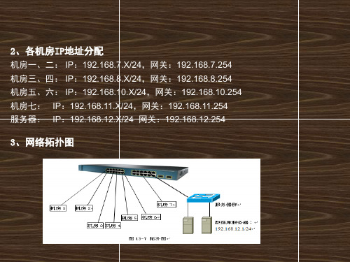
段的服务器。
2、各机房IP地址分配
机房一、二: IP:192.168.7.X/24,网关:192.168.7.254 机房三、四: IP:192.168.8.X/24,网关:192.168.8.254 机房五、六: IP:192.168.10.X/24,网关:192.168.10.254 机房七: IP:192.168.11.X/24,网关:192.168.11.254 服务器: IP:192.168.12.X/24 网关:192.168.12.254
3560(config)#access-list 102 deny ip 192.168.8.0 0.0.0.255 192.168.7.0 0.0.0.255 3560(config)#access-list 102 deny ip 192.168.8.0 0.0.0.255 192.168.10.0 0.0.0.255 3560(config)#access-list 102 deny ip 192.168.8.0 0.0.0.255 192.168.11.0 0.0.0.255 3560(config)#access-list 102 permit ip any any 3560(config)#access-list 103 deny ip 192.168.10.0 0.0.0.255 192.168.7.0 0.0.0.255 3560(config)#access-list 103 deny ip 192.168.10.0 0.0.0.255 192.168.8.0 0.0.0.255 3560(config)#access-list 103 deny ip 192.168.10.0 0.0.0.255 192.168.11.0 0.0.0.255 3560(config)#access-list 103 permit ip any any 3560(config)#access-list 104 deny ip 192.168.11.0 0.0.0.255 192.168.7.0 0.0.0.255 3560(config)#access-list 104 deny ip 192.168.11.0 0.0.0.255 192.168.8.0 0.0.0.255 3560(config)#access-list 104 deny ip 192.168.11.0 0.0.0.255 192.168.10.0 0.0.0.255 3560(config)#access-list 104 permit ip any any
cisco3560交换机所有配置命令

channel-group command 2-70
channel-protocol command 2-74
Cisco Network Assistant
See Network Assistant
Cisco Redundant Power System 2300
configuring 2-464
auto qos voip command 2-52
Auto Smartports macros and LLDP 2-347
B
BackboneFast, for STP 2-808
backup interfaces
configuring 2-882
displaying 2-593
boot helper command 2-62
boot helper-config file command 2-63
booting
Cisco IOS image 2-66
displaying environment variables 2-524
interrupting 2-61
manually 2-64
boot loader
accessing A-1
booting
Cisco IOS image A-3
helper image 2-62
directories
creating A-19
displaying a list of A-8
removing A-23
boot private-config-file command 2-65
boot system command 2-66
cisco3560思科交换机常用配置教程与实例
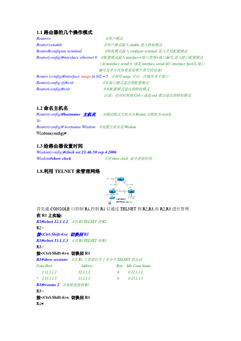
1.1路由器的几个操作模式Router>//用户模式Router>enable//用户模式敲入enable进入特权模式Router#configure terminal//特权模式敲入configure terminal进入全局配置模式Router(config)#interface ethernet 0//配置模式敲入interface+接口类型+接口编号,进入接口配置模式(如:interface serial 0 或是interface serial 0/1 ,interface fast1/1,接口编号是多少具体要看是哪个型号的设备)Router (config)#interface range fa 0/2 – 5//利用range可以一次操作多个端口Router(config-if)#exit //从接口模式退出到配置模式Router(config)#exit//从配置模式退出到特权模式注意:任何时候按Ctrl-z或是end都会退出到特权模式1.2命名主机名Router(config)#hostname 主机名//路由默认主机名为Router,交换机为switch如:Router(config)#hostname Wisdom//设置主机名是WisdomWisdom(config)#1.3给路由器设置时间Wisdom(config)#clock set 23:46:50 sep 4 2006Wisdom#show clock//用show clock 命令查看时间1.8.利用TELNET来管理网络首先通CONSOLE口控制R1,控制R1后通过TELNET到R2,R3,对R2,R3进行管理.在R1上实验:R1#telnet 12.1.1.2//从R1 TELNET到R2R2>按<Ctrl-Shift-6>x 切换回R1R1#telnet 13.1.1.3//从R1 TELNET到R3R3>按<Ctrl-Shift-6>x 切换回R1R1#show sessions//在R1上查看打开了多少个TELNET的会话Conn Host Address Byte Idle Conn Name1 12.1.1.2 12.1.1.2 0 0 12.1.1.2* 2 13.1.1.3 13.1.1.3 0 0 13.1.1.3R1#resume 2//重新连接到R3R3>按<Ctrl-Shift-6>x 切换回R1R1#R1#disconnect 1//从R1是主动断开到R2的连接(断开一个TELNET的会话)在R2上实验:R2#show users//在R2上查看有谁登录到路由器Line User Host(s) Idle Location* 0 con 0 idle 00:00:002 vty 0 idle 00:01:52 12.1.1.1R2#clear line 2//发现有人TELNET过来,把他清除R2#show usersLine User Host(s) Idle Location* 0 con 0 idle 00:00:00注意:Show session和show user的区别Disconnect 和Clear line的区别Ctrl+shift+6 x 和resume1.9 PING、TraceRoute、Debug、Sysloga.使用PING命令R1#ping 12.1.1.2如果ping的结果是!!!!!则表明网络正常.如果ping的结果是…..则表明网络不通.如果ping的结果是U.U.U则表明下一跳不可达.b.使用traceroute命令, 在网络层上追踪源到目的地址所经过的路由器.(或是数据包经过的路径)例:R2#traceroute 33.1.1.3Tracing the route to 33.1.1.31 12.1.1.1 4 msec 4 msec 4 msec2 13.1.1.34 msec 4 msec *//从以上可以看出从R2 到达33.1.1.3经过了12.1.1.1和13.1.1.3两个路由器例:………………………………………………………………………………………………………………….3.3使用串口管理交换机。
cisco3560参数
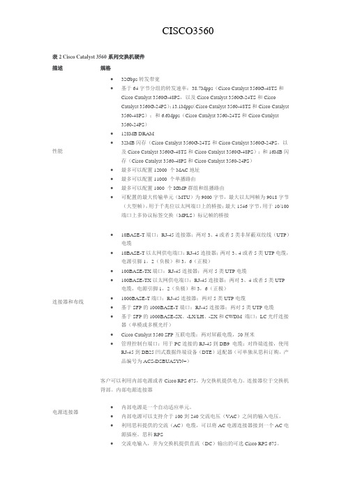
表2 Cisco Catalyst 3560系列交换机硬件描述规格性能∙32Gbps转发带宽∙基于64字节分组的转发速率:38.7Mpps(Cisco Catalyst 3560G-48TS和Cisco Catalyst 3560G-48PS,以及Cisco Catalyst 3560G-24TS和CiscoCatalyst 3560G-24PS);13.1Mpps(Cisco Catalyst 3560-48TS和Cisco Catalyst 3560-48PS);和6.6Mpps(Cisco Catalyst 3560-24TS和Cisco Catalyst3560-24PS)∙128MB DRAM∙32MB闪存(Cisco Catalyst 3560G-24TS和Cisco Catalyst 3560G-24PS,以及Cisco Catalyst 3560G-48TS和Cisco Catalyst 3560G-48PS);和16MB闪存(Cisco Catalyst 3560-48PS和Cisco Catalyst 3560-24PS)∙最多可以配置12000 个MAC地址∙最多可以配置11000 个单播路由∙最多可以配置1000 个IGMP群组和组播路由∙可配置的最大传输单元(MTU)为9000字节,最大以太网帧为9018字节(大型帧),用于千兆位以太网端口上的桥接;最大1546字节,用于10/100端口上多协议标签交换(MPLS)标记帧的桥接连接器和布线∙10BASE-T端口:RJ-45连接器;两对3、4或者5类非屏蔽双绞线(UTP)电缆∙10BASE-T以太网供电端口:RJ-45连接器;两对3、4或者5类UTP电缆,电源引脚1,2(负极)和3,6(正极)∙100BASE-TX端口:RJ-45连接器;两对5类UTP电缆∙100BASE-TX以太网供电端口:RJ-45连接器;两对3、4或者5类UTP 电缆,电源引脚1,2(负极)和3,6(正极)∙1000BASE-T端口:RJ-45连接器;两对5类UTP电缆∙基于SFP的1000BASE-T端口:RJ-45连接器;两对5类UTP电缆∙基于SFP的1000BASE-SX、-LX/LH、-ZX和CWDM 端口:LC光纤连接器(单模或多模光纤)∙Cisco Catalyst 3560 SFP互联电缆:两对屏蔽电缆,50厘米∙管理控制台端口:用于PC连接的RJ-45到DB9 电缆;对终端连接,使用RJ-45到DB25凹式数据终端设备(DTE)适配器(可单独从思科订购,产品编号为ACS-DSBUASYN=)电源连接器客户可以利用内部电源或者Cisco RPS 675,为交换机提供电力。
思科3560交换机中文配置手册
3560客户中文配置手册第1章概述 1-11.1 概述 1-11.2 初次访问设备 1-21.2.1 通过Console口访问设备 1-2第2章命令行方式访问设备 2-12.1.1 命令行模式 2-12.1.2 基本设置命令 2-12.2 通过Console口进入命令行接口 2-22.3 通过Telnet进入命令行接口 2-2第3章接口配置 3-13.1 概述 3-13.2 二层口配置 3-13.2.1 配置端口速率及双工模式 3-13.3 配置一组端口 3-23.4 配置三层口 3-33.5 监控及维护端口 3-53.5.1 监控端口和控制器的状态 3-53.5.2 刷新、重置端口及计数器 3-73.5.3 关闭和打开端口 3-83.6 交换机端口镜像配置 3-93.6.1 创建一个本地SPAN会话 3-103.7 以太通道端口组(Ethernet Port Groups) 3-11第4章配置VLAN 4-124.1 简介 4-124.2 可支持的VLAN 4-124.3 配置正常范围的VLAN 4-124.3.1 删除VLAN 4-144.3.2 将端口分配给一个VLAN 4-154.4 配置VLAN Trunks 4-164.5 配置VTP DOMAIN 4-184.6 配置VLAN接口地址 4-18第5章交换机HSRP配置 5-1第6章路由协议配置 6-36.1.1 静态路由 6-36.1.2 RIP路由 6-36.1.3 OSPF路由 6-5第1章概述1.1 概述3560交换机是支持二层、三层功能的交换机,共分为EMI,SMI两个版本Enhanced Multilayer Software Image增强多层软件镜像软件 (EMI)• EMI提供了一组更加丰富的企业级功能,包括基于硬件的高级IP单播和多播路由。
•支持双机热备(HSRP),OSPF路由功能.Standard Multilayer Software Image标准多层软件镜像软件(SMI)• SMI功能集包括高级QoS、速率限制、访问控制列表(ACL),以及基本的静态和路由信息协议(RIP)路由功能支持VLAN·到1005 个VLAN·支持VLAN ID从1到4094( IEEE 802.1Q 标准)·支持ISL及IEEE 802.1Q封装安全·支持IOS标准的密码保护·静态MAC地址映射·标准及扩展的访问列表支持,对于路由端口支持入出双向的访问列表,对于二层端口支持入的访问列表·支持基于VLAN的访问列表3层支持(需要多层交换的IOS)· HSRP· IP路由协议o RIP versions 1 and 2o OSPFo IGRP及EIGRPo BGP Version 4支持以下SFP模块:· 1000BASE-T SFP: 铜线最长100 m· 1000BASE-SX SFP: 光纤最长1804 feet (550 m)· 1000BASE-LX/LH SFP: 光纤最长32,808 feet (6 miles or 10 km) · 1000BASE-ZX SFP: 光纤最长328,084 feet (62 miles or 100 km) 管理从用户与设备交互的特点来分,访问设备的方式可以分为命令行方式和Web方式。
- 1、下载文档前请自行甄别文档内容的完整性,平台不提供额外的编辑、内容补充、找答案等附加服务。
- 2、"仅部分预览"的文档,不可在线预览部分如存在完整性等问题,可反馈申请退款(可完整预览的文档不适用该条件!)。
- 3、如文档侵犯您的权益,请联系客服反馈,我们会尽快为您处理(人工客服工作时间:9:00-18:30)。
G ETTING S TARTED G UIDECatalyst 3560 Switch Getting Started Guide1About this Guide, page 22Taking Out What You Need, page 23Running Express Setup, page 64Managing the Switch, page 85Installing the Switch, page 96Securing the AC Power Cord (Catalyst 3560 8- and 12-Port Switches), page 14 7Connecting to the Switch Ports, page 168In Case of Difficulty, page 189Obtaining Documentation and Submitting a Service Request, page 1910Cisco Limited Lifetime Warranty, page 201 About this GuideThis guide provides instructions on how to use Express Setup to configure your switch. It also includes information about switch management options, basic rack-mounting procedures, port and module connections, power connection procedures, and troubleshooting help.For additional installation and configuration information for Catalyst 3560 switches, see the Catalyst3560 documentation on . For system requirements, important notes, limitations, open and resolved bugs, and last-minute documentation updates, see the release notes, also on .When you use the online publications, refer to the documents that match the Cisco IOS software version running on the switch. The software version is on the Cisco IOS label on the switch rear panel.For translations of the warnings that appear in this publication, see the Regulatory Compliance and Safety Information for the Catalyst 3560 Switch included in the documentation CD.2 Taking Out What You Need1.Unpack and remove the switch and the accessory kit from the shipping box.2.Return the packing material to the shipping container, and save it for future use.3.Verify that you have received the items shown on page3. If any item is missing or damaged, contact your Ciscorepresentative or reseller for instructions. Some switch models might include additional items, and you might need to supply or to order some optional items.Equipment That You Supply to Run Express SetupYou need to supply this equipment:•PCEthernet (Category 5) straight-through cable (as shown)•2Shipping Box ContentsThe items shipped with your switch depend on the switch model and the options that you choose. Some items shown are optional, and your switch might look different.These items ship with the Catalyst 3560 24- and 48-port switches:1Catalyst 3560 switch8Four number-8 Phillips truss-head screws2Console cable9Six number-8 Phillips flat-head screws3AC power cord10Connector cover for redundant power system (RPS)4Four rubber mounting feet11Two number-4 pan-head screws5Documentation12Cable guide6Two 19-inch mounting brackets13One black Phillips machine screw7Four number-12 Phillips machine screws3These items ship with the Catalyst 3560 8- and 12-port switches:1Catalyst 3560 switch5Documentation2Console cable6Mounting magnet3AC power cord7Screw template4Four rubber mounting feet8Three number-8 Phillips pan-head screwsInstallation Warning StatementsSee the Regulatory Compliance and Safety Information for the Catalyst 3560 Switch on the documentation CD for translations of these warnings in the required languages.Warning Only trained and qualified personnel should be allowed to install, replace, or service this equipment. Statement 148 Warning To prevent the switch from overheating, do not operate it in an area that exceeds the maximum recommended ambient temperature of 113°F (45°C). To prevent airflow restriction, allow at least 3 inches (7.6 cm) of clearancearound the ventilation openings. Statement 17BWarning Installation of the equipment must comply with local and national electrical codes. Statement 10744Warning To prevent bodily injury when mounting or servicing this unit in a rack, you must take special precautions to ensure that the system remains stable. The following guidelines are provided to ensure your safety:•This unit should be mounted at the bottom of the rack if it is the only unit in the rack.•When mounting this unit in a partially filled rack, load the rack from the bottom to the top with the heaviest component at the bottom of the rack.•If the rack is provided with stabilizing devices, install the stabilizers before mounting or servicing the unit in the rack.Statement 1006Warning This equipment is intended to be grounded. Ensure that the host is connected to earth ground during normal use.Statement 39Warning If a redundant power system (RPS) is not connected to the switch, install an RPS connector cover on the back of the switch. Statement 265Warning Class 1 laser product. Statement 1008Warning For connections outside the building where the equipment is installed, the following ports must be connected through an approved network termination unit with integral circuit protection: 10/100/1000 Ethernet. Statement 1044 Warning Voltages that present a shock hazard may exist on Power over Ethernet (PoE) circuits if interconnections are made using uninsulated exposed metal contacts, conductors, or terminals. Avoid using such interconnection methods,unless the exposed metal parts are located within a restricted access location and users and service people whoare authorized within the restricted access location are made aware of the hazard. A restricted access area canbe accessed only through the use of a special tool, lock and key or other means of security. Statement 107253 Running Express SetupWhen you use Express Setup to enter the initial IP information, the switch can then connect to local routers and the Internet. For further configuration, you can access the switch through its IP address.67The Express Setup page appears. If it does not appear, see the “In Case of Difficulty” section on page18 for help.Step 10Enter this information in the Network Settings fields:•In the Management Interface (VLAN ID) field, the default is 1. Enter a different VLAN ID only if you want to change the management interface through which you manage the switch. The VLAN ID range is 1 to 1001.•In the IP Address field, enter the IP address of the switch. In the IP Subnet Mask field, click the drop-down arrow, and select an IP Subnet Mask .•In the Default Gateway field, enter the IP address for the default gateway (router).•Enter your password in the Switch Password field. The password can be from 1 to 25 alphanumeric characters, can start with a number, is case sensitive, allows embedded spaces, but does not allow spaces at the beginning or end. •In the Confirm Switch Password field, enter your password again.Step 11(Optional) You can enter the Optional Settings information now or enter it later by using the device manager interface:•In the Host Name field, enter a name for the switch. The host name is limited to 31characters. Do not use embedded spaces.•Enter the date, time, and time zone information in the System Date , System Time , and Time Zone fields. Click Enable to enable daylight saving time.Step 12(Optional) Click the Advanced Settings tab on the Express Setup window, and enter the advanced settings now or enter them later by using the device manager interface.Step13(Optional) Enter this information in the Advanced Setting fields:•In the Telnet Access field, click Enable if you are going to use Telnet to manage the switch by using the command-line interface (CLI). If you enable Telnet access, you must enter a Telnet password.•In the Telnet Password field, enter a password. The Telnet password can be from 1 to 25 alphanumeric characters, is case sensitive, allows embedded spaces, but does not allow spaces at the beginning or end. In theConfirm Telnet Password field, re-enter the Telnet password.•In the SNMP field, click Enable to enable Simple Network Management Protocol (SNMP). Enable SNMP only if you plan to manage switches by using CiscoWorks2000 or another SNMP-based network-managementsystem.•If you enable SNMP, you must enter a community string in the SNMP Read Community field, the SNMP Write Community field, or both. SNMP community strings authenticate access to MIB objects. Embedded spaces arenot allowed in SNMP community strings. When you set the SNMP read community, you can access SNMPinformation, but you cannot modify it. When you set the SNMP write community, you can both access andmodify SNMP information.•In the System Contact and System Location fields, enter a contact name and the wiring closet, floor, or building where the switch is located.Step14(Optional) You can enable Internet Protocol version 6 (IPv6) on the switch, which requires that your switch is running IP advanced services software. From the Advanced Settings tab, check the Enable IPv6 check box. Enabling IPv6 restarts the switch after you complete Express Setup.Step15To complete Express Setup, click Submit from the Basic Settings or the Advanced Settings tab to save your settings (clicking Cancel clears your settings).When you click Submit, the switch is configured and exits Express Setup mode. The PC displays a warning message and tries to connect with the new switch IP address. If you configured the switch with an IP address that is in adifferent subnet from the PC, connectivity between the PC and the switch is lost.Step16Disconnect the switch from the PC, and install the switch in your production network. See the “Managing the Switch” section on page8 for information about configuring and managing the switch.If you need to rerun Express Setup, see the “Resetting the Switch” section on page18.Refreshing the PC IP AddressAfter you complete Express Setup, you should refresh the PC IP address.For a dynamically assigned IP address, disconnect the PC from the switch, and reconnect it to the network. The network DHCP server assigns a new IP address to the PC.For a statically assigned IP address, change it to the previously configured IP address.4 Managing the SwitchAfter you complete Express Setup and install the switch in your network, use the device manager or other management options described in this section for further configuration.Using the Device ManagerYou can manage the switch by using the device manager that is in the switch memory. You can access the device manager from anywhere in your network through a web browser.1.Open a web browser.2.Enter the switch IP address in the web browser, and press Enter. The device manager page appears.e the device manager to perform basic switch configuration and monitoring. Refer to the device manager online help formore information.4.For more advanced configuration, install Cisco Network Assistant as described in the next section.8Downloading Cisco Network AssistantYou can download Cisco Network Assistant from to run on your PC. It offers advanced options for configuring and monitoring multiple devices, including switches, switch clusters, switch stacks, routers, and access points. There is no charge to download, install, or use Cisco Network Assistant.1.You must be a registered user, but you need no other access privileges./go/NetworkAssistant2.Find the Network Assistant installer.3.Download the Network Assistant installer, and run it. (You can run it directly from the Web if your browser offers thischoice.)4.When you run the installer, follow the instructions. In the final panel, click Finish to complete the Network Assistantinstallation.Refer to the Network Assistant online help and the getting started guide for more information.Command-Line InterfaceYou can enter Cisco IOS commands and parameters through the CLI. Access the CLI either by connecting your PC directly to the switch console port or through a Telnet session from a remote PC or workstation.1.Connect the adapter cable to the standard 9-pin serial port on the PC. Connect the other end of the cable to the consoleport on the switch.2.Start a terminal-emulation program on the PC.3.Configure the PC terminal emulation software for 9600 baud, 8 data bits, no parity, 1 stop bit, and no flow control.e the CLI to enter commands to configure the switch. See the software configuration guide and the command referencefor more information.Other Management OptionsYou can use SNMP management applications such as CiscoWorks Small Network Management Solution (SNMS) andHP OpenView to configure and manage the switch. You also can manage it from an SNMP-compatible workstation that is running platforms such as HP OpenView or SunNet Manager.The Cisco IE2100 Series Configuration Registrar is a network management device that works with embedded CNS agents in the switch software. You can use IE2100 to automate initial configurations and configuration updates on the switch.See the “Accessing Troubleshooting Information on ” section on page19 for a list of supporting documentation.5 Installing the SwitchDepending on the model, you can install the switch in a rack, on a wall, on or under a desk or shelf, and with a magnet or rack-mount brackets. For other mounting procedures, see the Catalyst 3560 Switch Hardware Installation Guide on . Equipment That You SupplyYou need this equipment to install the switch:•Number-2 Phillips screwdriver•Drill with a #27 drill bit (0.144-inch [3.7 mm]). A drill is required for securing the Catalyst 3560 8- or 12-port switch to a desk or a wall.910Before You BeginWhen you determine where to install the switch, follow these guidelines:Rack-Mounting the Switch (Catalyst 3560 24- and 48-Port Switches)This section applies to the Catalyst 3560 24- and 48-port switches. For the Catalyst 3560 8-and 12-port switches, see “Securing the Switch on a Desk or Shelf (Catalyst 3560 8- and 12-Port Switches)” section on page 13 and “Mounting the Switch with a Magnet (Catalyst 3560 8- and 12-Port Switches)” section on page 14.This section covers basic 19-inch rack-mounting. The Catalyst 3560G-48PS switch is shown as an example. You can install and connect other 24- and 48-port Catalyst 3560 switches as shown.•Airflow around the switch and through the vents isunrestricted. Allow at least 3inches (7.6 cm) of clearance around the ventilation openings. Do not stack switches, and do not place the 8- or 12-port switches side-by-side.•When you place the 8- or 12-port switch on a flathorizontal surface without the magnet, attach the rubber feet to the switch to prevent airflow restriction and overheating.•Allow at least 1.75inches (4 cm) of clearance above each 8- or 12-port switch in the rack.•Wall-mount the 8- or 12-port switch with its front panel facing down to prevent airflow restriction and to provide easier access to the cables.•Do not place any items on the top of the switch.•Clearance to the switch front and rear panels meets these conditions:–You can easily read the front-panel LEDs.–Access to ports is sufficient for unrestricted cabling.–The power cord can reach from the power outlet tothe connector on the switch rear panel.•Temperature around the switch does not exceed 113°F (45°C).•Humidity around the switch does not exceed 85 percent.•Altitude at the installation site is not greater than 10,000 feet.•The heatsinks and the bottom of the 8- or 12-port switch might be hot to the touch if the switch is operating at its maximum temperature 113°F (45°C) in an environment that exceeds normal room temperature (such as in a closet, in a cabinet, or in a closed or multirack assembly).•Cabling is away from sources of electrical noise, such as radios, power lines, and fluorescent lighting fixtures.•For 10/100 ports and 10/100/1000 ports, the cable length from a switch to an attached device cannot exceed 328 feet (100 meters).•For cable lengths for small form-factor pluggable (SFP) modules, see the documentation that shipped with the module.Attaching the BracketsUse four Phillips flat-head screws to attach the long side of the brackets to the switch in one of these mounting positions:11Mounting the Switch in a RackUse the black Phillips machine screw to attach the cable guide to the left or right bracket. Use the four number-12 Phillips machine screws to attach the brackets to the rack.1Black Phillips machine screws4Number-12 Phillips machine screws2Cable guide5Mid-rack mounting position (telco rack)3Front-mounting position6Rear-mounting position12Securing the Switch on a Desk or Shelf (Catalyst 3560 8- and 12-Port Switches)To place a Catalyst 3560 8- or 12-port switch on a desk without using the mounting screws, attach the four rubber feet to the bottom panel of the switch.To secure Catalyst 3560 8- or 12-port switch on top of or under a desk or a shelf, or on a wall, use the mounting template and three mounting screws:1.Position the screw template on the mounting surface with the two side-by-side slots forward. Peel the adhesive strip off thebottom, and attach the template.e a 0.144-inch (3.7 mm) or a #27 drill bit to drill a 1/2-inch (12.7 mm) hole in the template screw slot positions.3.Insert the screws in the slots on the template, and tighten until they touch the template. Remove the template from themounting surface.1Number-8 Phillips pan-head screws2Mounting template4.Place the switch onto the mounting screws, and slide it forward until it locks in place.13Mounting the Switch with a Magnet (Catalyst 3560 8- and 12-Port Switches)According to safety regulations, when you mount the switch with a magnet, make sure its front panel faces down to prevent airflow restriction and to provide easier access to the cables. This requires that you mount the switch with a magnet only on a vertical magnetic surface such as a metal filing cabinet.1.Position the mounting magnet on the mounting surface.2.Place the bottom of the switch on the magnet.The AC power-cord retainer is an optional part (PWR-CLIP-CMP).1415167 Connecting to the Switch PortsThis section describes how to connect to the switch, SFP module, and dual-purpose ports and how to verify your connections. For additional cabling information, see the Catalyst 3560 Switch Hardware Installation Guide on .Connecting to 10/100 and 10/100/1000 PortsThe fixed ports on the Catalyst 3560 Power over Ethernet (PoE) switches provide PoE support for devices compliant with IEEE 802.3af and also provide Cisco pre-standard PoE support for Cisco IP Phones and Cisco Aironet Access Points.Each of the Catalyst 3560-24PS switch 10/100 ports or the Catalyst 3560G-24PS switch 10/100/1000 ports can deliver up to 15.4W of PoE. On the Catalyst 3560-48PS or 3560G-48PS switches, any 24 of the 48 10/100 or 10/100/1000 ports can deliver 15.4W of PoE, or any combination of the ports can deliver an average of 7.7W of PoE at the same time, up to a maximum switch power output of 370W.By default, a Catalyst 3560 switch PoE port automatically provides power when a valid powered device is connected to it. For information about configuring and monitoring PoE ports, see the switch software configuration guide. For information about troubleshooting PoE problems, see the Catalyst 3560 Switch Hardware Installation Guide on .For simplified cabling, the automatic medium-dependent interface crossover (auto-MDIX) feature is enabled by default on the switch. With auto-MDIX enabled, the switch detects the required cable type for copper Ethernet connections and configures the interfaces accordingly. Therefore, you can use either a crossover or a straight-through cable for connections to a switch 10/100 or 10/100/1000 Ethernet port, regardless of the type of device on the other end of the connection.Installing an SFP Module and Connecting to a Module PortStep 1Step 2Step 117For a list of supported modules, see the release notes on . For detailed instructions on installing, removing, and connecting to SFP modules, see the corresponding documentation for the SFPmodule.often than is absolutely necessary.Connecting to a Dual-Purpose PortVerifying Port ConnectivityAfter you connect to the switch port, the port LED turns amber while the switch establishes a link. This process takes about 30seconds, and then the LED turns green after the switch and the target device have an established link. If the LED is off, the target device might not be turned on, there might be a cable problem, or there might be a problem with the adapter installed in the target device. See the “In Case of Difficulty” section on page 18 for information about online assistance.Step 2Step 3Step 1Step 2188 In Case of DifficultyIf you experience difficulty, help is available here and on . This section includes Express Setup troubleshooting, how to reset the switch, how to access help on , and where to find more information.Troubleshooting Express SetupIf Express Setup does not run, or if the Express Setup page does not appear in your browser:Resetting the SwitchWhy you might want to reset the switch:•You installed the switch in your network and cannot connect to it because you assigned the wrong IP address.•You want to clear all configuration from the switch and assign a new IP address.•You are trying to enter Express Setup mode, and the switch LEDs start blinking when you press the Mode button, whichmeans that the switch is already configured with IP information.To reset the switch, press and hold the Mode button. The switch LEDs begin blinking after about 3seconds. Continue holding down the Mode button. The LEDs stop blinking after 7 more seconds, and then the switch reboots.•Did you verify that POST ran successfully before starting Express Setup?If not, make sure that only the SYST and STAT LEDs are green before you press the Mode button to enter the Express Setupmode.•Did you press the Mode button while the switch was still running POST?If yes, wait until POST completes. Power cycle the switch. Wait until POST completes. Confirm that the SYST and STATLEDs are green. Press the Mode button to enter Express Setup mode.•Did you try to continue without confirming that the switch was in Express Setup mode?Verify that all LEDs above the Mode button are green. (On some models, the RPS LED is off.) If necessary, press the Mode button to enter Express Setup mode.•Does your PC have a static IP address?If yes, change your PC settings to temporarily use DHCP before connecting to the switch.•Did you connect a crossover cable instead of a straight-through Ethernet cable between a switch port and the Ethernet port of the PC?If yes, connect a straight-through cable to an Ethernet port on the switch and the PC. Wait 30 seconds before entering 10.0.0.1 in the browser.•Did you connect the Ethernet cable to the console port instead of to a 10/100 or 10/100/1000 Ethernet port on the switch?If yes, disconnect from the console port. Connect to an Ethernet port on the switch and the PC. Wait 30 seconds before you enter 10.0.0.1 in the browser.•Did you wait 30 seconds after you connected the switch and the PC before you entered the IP address in your browser?If not, wait 30 seconds, re-enter 10.0.0.1 in the browser, and press Enter .•Did you enter the wrong address in the browser, or is there an error message?If yes, re-enter 10.0.0.1 in the browser, and press Enter .The switch now behaves like an unconfigured switch. You can enter the switch IP information by using Express Setup as described in the “Running Express Setup” section on page6.Accessing Troubleshooting Information on First look for a solution to your problem in the troubleshooting section of the Catalyst 3560 Hardware Installation Guide or the Catalyst 3560 Software Configuration Guide on . You can also access the Cisco Technical Support and Documentation website for a list of known hardware problems and extensive troubleshooting documentation, including:•Factory defaults and password recovery•Recovery from corrupted or missing software•Switch port problems•Network interface cards•Troubleshooting tools•Field notices and security advisoriesFollow these steps:1.Open your browser, and go to /.2.Click Support > Select Your Product > Switches > LAN Switches > Catalyst 3560 Series Switches > Troubleshooting andAlerts.3.Click the subject that addresses the problem that you are experiencing.For More InformationFor more information about the switch, see these documents on :•Release Notes for the Catalyst 3750, 3560, 2970, and 2960 Switches. Before you install, configure, or upgrade the switch, refer to the release notes on for the latest information.•Catalyst 3560 Switch Hardware Installation Guide for complete hardware descriptions and detailed installation procedures.•Regulatory Compliance and Safety Information for the Catalyst 3560 Switch for agency approvals, compliance information, and translated warning statements.•Catalyst 3560 Switch Software Configuration Guide for detailed descriptions and procedures of the switch software features.•Catalyst 3560 Switch Command Reference for detailed descriptions of the Cisco IOS commands specifically created or modified for the switch.•Catalyst 3750, 3560, 3550, 2970, and 2960 Switch System Message Guide for descriptions of the system messages specifically created or modified for the switch.•Device manager online help (available on the switch)•Cisco Network Assistant online help (available on the switch)9 Obtaining Documentation and Submitting a Service RequestFor information on obtaining documentation, submitting a service request, and gathering additional information, see the monthly What’s New in Cisco Product Documentation, which also lists all new and revised Cisco technical documentation, at: /en/US/docs/general/whatsnew/whatsnew.htmlSubscribe to the What’s New in Cisco Product Documentation as a Really Simple Syndication(RSS) feed and set content to be delivered directly to your desktop using a reader application. The RSS feeds are a free service and Cisco currently supportsRSS Version2.0.19Americas HeadquartersCisco Systems, Inc.San Jose, CAAsia Pacific HeadquartersCisco Systems (USA) Pte. Ltd.SingaporeEurope HeadquartersCisco Systems International BV Amsterdam, The NetherlandsCisco has more than 200 offices worldwide. Addresses, phone numbers, and fax numbers are listed on theCisco Website at /go/offices .OL-17734-0110 Cisco Limited Lifetime WarrantySee the documentation CD that shipped with this product for a description of the warranty terms.CCDE, CCENT, Cisco Eos, Cisco Lumin, Cisco Nexus, Cisco StadiumVision, Cisco TelePresence, Cisco WebEx, the Cisco logo, DCE, and Welcome to the Human Network are trademarks; Changing the Way We Work, Live, Play, and Learn and Cisco Store are service marks; and Access Registrar, Aironet, AsyncOS, Bringing the Meeting To You, Catalyst, CCDA, CCDP, CCIE, CCIP, CCNA, CCNP, CCSP, CCVP, Cisco, the Cisco Certified Internetwork Expert logo, Cisco IOS, Cisco Press, Cisco Systems,Cisco Systems Capital, the Cisco Systems logo, Cisco Unity, Collaboration Without L imitation, EtherFast, EtherSwitch, Event Center, Fast Step, Follow Me Browsing,FormShare, GigaDrive, HomeLink, Internet Quotient, IOS, iPhone, iQuick Study, IronPort, the IronPort logo, LightStream, Linksys, MediaTone, MeetingPlace, MeetingPlace Chime Sound, MGX, Networkers, Networking Academy, Network Registrar, PCNow, PIX, PowerPanels, ProConnect, ScriptShare, SenderBase, SMARTnet, Spectrum Expert, StackWise, The Fastest Way to Increase Your Internet Quotient, TransPath, WebEx, and the WebEx logo are registered trademarks of Cisco Systems,Inc. and/or its affiliates in the United States and certain other countries.All other trademarks mentioned in this document or website are the property of their respective owners. The use of the word partner does not imply a partnership relationship between Cisco and any other company. (0809R)。
