液压系统安装中的污染控制外文文献翻译、中英文翻译
液压系统的形式及评价外文翻译
The hydraulic presses system of the form and the evaluationThe hydraulic presses the component to carried out to standardize gradually, the series turn, its specification, species, quantity, functionses all had to raise very greatly, particularly is to adopt the new craft of new technique of electronics technique, servo technique...etc. after, the hydraulic presses the exaltation that the quantity of the system gets to show the highest , it developped the important function in national economy and the military industries.Set out from the different angle, can press the system to the liquid to be divided into the different form.1)Press the circulating way of the oil liquid, the liquid press the system and can is divided into the open type system and shut type systems.The open type system mean that the liquid presses the pump to absorb the oil from the fuel tank, the oil is through various control valve, driving the liquid to press to carry out the component, returning to oil to has been changed to return to fuel tank toward valve again.This kind of system structure is more simple, can develop the fuel tank to spread hot, precipitate the miscellaneous quality function, but often get in touch with with air because of the oil liquid, make air be easy to seep into the system, causing the organization exercise the gravamen steady etc. result.The open type system fuel tank is big, oil pump from absorb the function and like.In the shut type system, the liquid presses the pump of into pipeline directly with performance the component return to pipeline connect with each other, work the liquid carries on closing the circulation in the tube road of the system.Its structure tightly packed, with the air opportunity to get in touch with little, not easy infiltration system of air, so spread to move more steady.The work organization become soon and change to depend to regulate the pump or motors to change to measure the organization realization, avoided the open type system change toward process appear of liquid press the impact and energy losses.But the shut type system more the open type system complications, because of having no fuel tank, the oil liquid spread hot and filter the condition is worse.In order to compensate the leakiness in the system, usually need a small discharge to repair the oil pump and fuel tanks.Because the oil a size of a function of high bar discharge not etc., will make power make use of descend in work process, so the performance component within the shut type system presses the motor for the liquid generally.2)According to system the liquid presses the number of the pump, can is divided into the list pump system, double pump system and pump system more.3)Press the dissimilarity of pump the form with the liquid by, can is divided into the fixed amount pump system and change the quantity pump system.The advantage that changes to measure the pump is to regulate the scope inside, can make use of the power of launch the machine well, but its structure and the manufacturing craft complications, the cost is high, can is divided in to move to change the quantity, control to change the quantity possibly, servo change the quantity, pressure to compensate to change the quantity, press to change the quantity, liquid to press to change to measure various ways of etc..4)Press toward performance the component to provide the dissimilarity of the oil method, can is divided in to establish the system and merge the system.Establish in the system, it is next performance component that previous performance component return to oil of into oil, pass a performance component pressure and will lower once each time.In establish system, the each performance component that be the lord pump toward many roads valve control provides the oil,as long as the liquid presses the exit pressure of the pump enough, the compound of the sport that can carry out each performance component then.But the pressure of the performance component is to fold to add of, so overcome the outside carry ability will with carry out the increment of the component quantity but lower.Merge in the system, be a the pedestal liquid to press the pump toward a performance component to provide the oil, discharge that enters each performance component be just the liquid press the pump exportation discharge of a part.The allotment of the discharge with each last the outside carries the lotus of dissimilarity but variety, enter first outside carry the smaller performance component of lotus, only be each performance component up outside carry the lotus equality, then can carry out to act at the same time.The whole liquid presses to spread the good and bad of move the machine function, mainly being decided by the quality that the liquid presses the system function, including the component quantity good and bad use, basic back track whether fitting etc..The quality of the system function, in addition to satisfying to use the function to request, should make use of, adjust from the efficiency, power that the liquid press the system soon scope and tiny adjust characteristic, vibration and voice of noises and the gearing of the systems and adjust to try whether convenient credibility etc. carry on.The modern engineering machine almost adopts the liquid to press the system, and combine with electronics system, the calculator control technique, the importance that become the modern engineering machine constitutes the part.液压系统的形式及评价液压元件逐步实现了标准化、系列化,其规格、品种、质量、性能都有了很大提高,尤其是采用电子技术、伺服技术等新技术新工艺后,液压系统的质量得到了显著的提高,其在国民经济及军事工业中发挥了重大作用。
数控系统辅助液压挖掘机的概念外文文献翻译、中英文翻译、外文翻译
AbstractA concept of digital control system to assist the operators of hydraulic excavators is presented and discussed. Then, control system based on described ideas was mounted on a special numerically controlled stand, equipped with D r A and A r D converters, where small hydraulic backhoe excavator K-111 fixtures were used. Experimental results shows that it fulfils all described requirements and can be used as the machine operator assist. It enables for precision tool guidance. automatic repetition of realized movements, realization of specific tool trajectories including energetically optimal path sand automatic improvement or optimization of realized paths. Tool trajectories can also be prescribed using the setting model, making excavator the machine of tele operator class. Presented system can be used as a basis for real machine control system. q 1998 Elsevier Science B.V. All rights reserved.Keywords: Digital control system; Hydraulic excavators; Tool trajectories1. IntroductionThe automation of heavy machines, including hydraulic excavators, began in mid-1970s and was possible due to invention of real time controllers and hydraulic elements with good dynamic properties. The first excavator equipped with several mechatronics systems, which was shown as a working model, was the excavator FUTURE prepared by Orenstein and Koppel for BAUMA’83 Fairs. Since that time, machines equipped with systems automating the engine operation, pumps operation, machine fixtures, machine diagnostic, etc.,are presented and offered. Such systems bring real help to the operator and clear economical profit. For example, LIEBHERRR902 excavator equipped with LITRONIC System. has for a trench digging the efficiency 40% higher and unit costs 30% lower, than similar machine without such automatic system. Although automationŽ. in some case, optimization of several machine systems develops quite fast, the main machine process—the shoving process—has no proper understanding and description until now. Its automation is quiteŽlimited to systems repeating already performed. movements, laser levelling systems, etc. and systems optimizing such processes are not developed yet. Quite new experimental results show clear idea for energetically optimal tool trajectories in the case of cohesive materials. The tool tip has to be guided along slip lines, which are generated from the tiptool during the previous stage of the shoving process. To realize such trajectories for practical purpose and real machines, it is necessary to build a special control system for the tool motion, which enables automatic realization of such trajectories as well as realization of other tasks that help the operator.2. The basic concept of the computer aided control systemItIt was shown before that analyzing the the soil deformation during the shoving process, it is possible to determine energetically optimal cutting tool trajectories. Hence, the automatic tool movement along slip lines generated in cohesive material has to be a quite important option of proposed system. It should also enable precision tool guidance, automatic repetition of already realized movementsŽ. for example, ‘teach-in’ , realization of some tool movements impossible to realize manually, etc. Taking into account to-day experience with automation of heavy machines, such system should be constructed to assist machine operator, who still plays a main decisive and control role. Hence, the proper separation of tasks, between the control sys-tem and the operator, is necessary. Such control system for excavators was built on laboratory scale. Its basic assumptions can be stat d w x Ž . as follows 13 : 1 operation of the central control system is based on cooperation of two digital systems. The first one controls directly the motion of the machine fixture using the control system of the hydraulic cylinders position. The second one worksŽ. out control signals for the first one. 2 Under the standard work conditions, action of the proportional hydraulic valves of the fixture cylinders is controlled through the computer. The direct operator control isŽ. possible only in case of emergency conditions. 3The feedback between the machine environment and control system is realized through the operator. He participates continuously in the process of the con-Ž. control of machine fixtures motion. 4 For realization of the tool motions which are impossible for manual control, the operator has a possibility to coordinate displacement of separate cylinders by means of hard-Ž. ware or software. 5 The operator has a possibility to switch into automatic control of the fixture motionto realize a special tool trajectories. For example, it can be energetically optimal tool trajectory where tool tip moves along slip lines or specific trajectoryŽ. realized and stored previously. 6 The optimal cut-ting tool trajectories can also be realized as correction of trajectories given by the operator. Such correction is done mainly during the time parametrization of the tool path. 7 The trajectories given by the operator can be corrected by the system to take in toaccount such limitations as geometrical ones, maxi-mal power of the pump, maximal output of the pump, maximal pump efficiency, etc.Presented concept is based on such cooperation between the operator and control system that the fixture movements are controlled by the operator while the control system corrects him or, when ordered, can act automatically3. Examples of the control system functioningThe control system based on described above ideas was mounted on a special numerically con-trolled stand, equipped with PC computer having CrA and ArC converters, where small hydraulicw x backhoe excavator K-111 fixtures were used 14–17 .The control system of the fixture motions utilizes the control system of the cylinder positions. The fixture cylinder displacement is controlled by the proportional hydraulic valves fed by the variable out putmultipiston pump. The control system for fixture cylinders is based on three control systems, each to control different cylinder displacement using PID or state control ler w x 14 . It enables control of the fixture motions using different methods of the tool trajectory planning, measuring of acting forces and displacements and determining other magnitudes related to the fixture movements. Experimental data acquisition is also possible. One of quite important problems, which should betaken into account when building the control system, is the way of the tool trajectory planning. It isŽ. w x realized as usually in two steps 15 . In the first one, the trajectory shape is planned and determined. In the second one, the trajectory curve is parametric zed in time in a determined manner, what defines the trajectory within the generalized coordinate space. On this basis, the time runs of the generalized coordinates describing the configuration space of the machine are determined. In the case of an excavator, lengths of hydraulic cylinders are thosecoordinates3.1. The tool moÕement along prescribed lineThe control system build for experimental standw x 15–17 enables, among others, programming the work motion in the excavator work space, or in its configuration space, using ‘point to point’ technique. In this method, the coordinates of the initial and final points, and sufficient number of the character isticnodal points, are defined. Values describing this points are then introduced to the system, where remaining points of the trajectory are calculated using interpolation methods. Linear or the third degree polynomial interpolation is used. The trajectory y parametrization in time can be realized through:–determination of the total trajectory run-time and its division into individual segments of the path. System calculates the velocities of cylinders,–determination of the run-time between following nodal points, taking into account some limitationsŽ. or conditions for optimization .In the case of standard excavator construction, it is quite difficult to precisely realize trajectories, where simultaneous movement of two or three cylinders is necessary.3.2. The tool moÕement using the setting modelalong straight lines In presented case, the coordination of the fixture cylinder movement was realized by hardware, that means using the setting model. It can also be realizedŽby software. The machine operator using special. buttons , can generate horizontal or vertical tool movement preserving the constant value of the tool cutting angle in every point of the machine working space. The prescribed tool path is stored using the point method in the configuration space. Further-more, the machine operator determines motion velocity which is corrected by control system taking in to account the feeder output. In Figs. 7 and 8, results of such control for the horizontal tool movement are shown. The cutting tool trajectory is presented in Fig. 7. In Fig. 8, the fixture cylinder lengths calculated for prescribed velocity are drawn with solid line. Their calculated lengths assumes the feed erout put are drawn with dotted line. The way of the tool path time parametrization was similar to that using the setting model. It is seen that velocities given by the operator are too high and system corrected cylinder motion timing to keep assumed feeder output. The example of the tool motion along the inclined line is presented in Figs. 9 and 10, where the tool trajectory and corresponding cylinder lengths are drawn. Such movement is realized as a sum ofŽhorizontal and vertical tool motions the line inclination depends on proportions between horizontal and. vertical velocities . For example, the tool trajectory long inclined line can be realized during theŽ. ‘withdraw’ stage of the shoving process Fig. 2 to follow the slip line or for automated, making the soil scarps.3.3. Automatic tool moÕement along a slip lineAnalysis of experimental results of the soil shoving process shows that it is possible to predict theoretically the slip lines positions and energy etically optimal tool trajectories. It can be done for homogeneous material under laboratory conditions. In real situations, when material is not homogeneous and not well-defined, the material sleep lines has to be detected automatically. The procedure of automatic slip line detection is based on the observation that when cutting tool begins to penetrate more dense material, then the in crease of the horizontal force acting on the tool is observed. Such situation takes place also when theŽtool tip moves from the slip line where material. Ž density is quite small to the virgin material material. not deformed before—behind the slip line . Hence, the observed increase of the pushing force can beused for slip line detection. Such procedure, which simplified version is described below, can berealized as follows. Cutting tool motion is realized as a sum of horizontal, vertical and rotational movements and horizontal reaction of the soil is measured and followed. Firstly, the tool moves horizontally up to the moment when the horizontal force drops, that coincides with creation of slip lines system originating from the toolŽ. end Fig. 1 . If such slip lines cannot be created as a Žresult of horizontal pushing, a special procedure for. example tool rotation can be applied. Then, tool is moved vertically by prescribed displacement valueŽand then moves again horizontally rotation of the. tool can be added up to the moment when horizontal force begins to increase. If so, , and then horizontally, and so on. This way, the tip of the tool automaticallyŽfollows in a step way the slip line. Results of such preliminary tests are presented in Figs. 11 and 12. As a simplified model, the possibility of automatic tool movement along the soil scarpinclined with 0.61 rad. was investigated. For defined values of maximum horizontal force and defined vertical displacement, the control system automatically followed the tool along the scarp. The horizontal force vs. horizontal displacement and tool trajectory are shown in Fig. 11. The magnified fragment of Fig. 11, which shows the way in which system is acting, is presented in Fig.12.4. ConclusionsExperimental results show that presented control system fulfils all described requirements and can be used as the machine operator assist. It enables for precision tool guidance, automatic repetition of realized movements, realization of specific tool trajectories including energetically optimal paths and automatic improvement or optimization of realized paths. Tool trajectories can also be prescribed using the setting model, making excavator the machine of tele operator class. Presented system can be used as abas is for real machine control system. Acknowledgements This research was sponsored by the Project KBN7T07C00412 ‘Optimization of the soil shoving process due to heavy machines of an excavator type’ realized at Kielce University of Technology.数控系统辅助液压挖掘机的概念摘要数控系统辅助液压挖掘机操作者的概念被提出和讨论。
液压系统外文文献翻译、中英文翻译、外文文献翻译
附录Hydraulic SystemHydraulic presser drive and air pressure drive hydraulic fluid as the transmission is made according to the 17th century, Pascal's principle of hydrostatic pressure to drive the development of an emerging technology, the United Kingdom in 1795 •Barman Joseph (Joseph Barman, 1749-1814), in London water as a medium to form hydraulic press used in industry, the birth of the world's first hydraulic press. Media work in 1905 will be replaced by oil-water and further improved.After the World War I (1914-1918) ,because of the extensive application of hydraulic transmission, especially after 1920, more rapid development. Hydraulic components in the late 19th century about the early 20th century, 20 years, only started to enter the formal phase of industrial production. 1925 Vickers (F. Vickers) the invention of the pressure balanced vane pump, hydraulic components for the modern industrial or hydraulic transmission of the gradual establishment of the foundation. The early 20th century G • Constantia scofluctuations of the energy carried out by passing theoretical and practical research; in 1910 on the hydraulic trans- mission (hydraulic coupling, hydraulic torque converter, etc.) contributions, so that these two areas of development.The Second World War (1941-1945) period, in the United States 30% of machine tool applications in the hydraulic transmission. It should be noted that the development of hydraulic transmission in Japan than Europe and the United States and other countries fornearly 20 years later. Before and after in 1955, the rapid development of Japan's hydraulic drive, set up in 1956, "Hydraulic Industry." Nearly 20 to 30 years, the development of Japan's fast hydraulic transmission, a world leader.Hydraulic transmission There are many outstanding advantages, it is widely used, such as general industrial use of plastics processing machinery, the pressure of machinery, machine tools, etc.; operating machinery engineering machinery, construction machinery, agricultural machinery, automobiles, etc.; iron and steel industry metallurgical machinery, lifting equipment, such as roller adjustment device; civil water projects with flood control and dam gate devices, bed lifts installations, bridges and other manipulation of institutions; speed turbine power plant installations, nuclear power plants, etc.; ship from the deck heavy machinery (winch), the bow doors, bulkhead valve, stern thruster, etc.; special antenna technology giant with control devices, measurement buoys, movements such as rotating stage; military-industrial control devices used in artillery, ship anti- rolling devices, aircraft simulation, aircraft retractable landing gear and rudder control devices and other devices.A complete hydraulic system consists of five parts, namely, power components, the implementation of components, control components, auxiliary components and hydraulic oil.The role of dynamic components of the original motive fluid into mechanical energy to the pressure that the hydraulic system of pumps, it is to power the entire hydraulic system. The structure of the form of hydra- ulic pump gears are generally pump, vane pump and piston pump.Implementation of components (such as hydraulic cylinders and hydraulic motors) which isthe pressure of the liquid can be converted to mechanical energy to drive the load for a straight line reciprocating movement or rotational movement.Control components (that is, the various hydraulic valves) in the hydraulic system to control and regulate the pressure of liquid, flow rate and direction. According to the different control functions, hydraulic pressure control valve can be divided into valves, flow control valves and directional control valve. Pressure control valves are divided into benefits flow valve (safety valve), pressure relief valve, sequence valve, pressure relays, etc.; flow control valves including throttle, adjusting the valves, flow diversion valve sets, etc.; directional control valve includes a one-way valve , one-way fluid control valve, shuttle valve, valve and so on. Under the control of different ways, can be divided into the hydraulic valve control switch valve, control valve and set the value of the ratio control valve.Auxiliary components, including fuel tanks, oil filters, tubing and pipe joints, seals, pressure gauge, oil level, such as oil dollars.Hydraulic oil in the hydraulic system is the work of the energy transfer medium, there are a variety of mineral oil, emulsion oil hydraulic molding Hop categories.The role of the hydraulic system is to help humanity work. Mainly by the implementation of components to rotate or pressure into a reciprocating motion.Hydraulic system and hydraulic power control signal is composed of two parts, the signal control of some parts of the hydraulic power used to drive the control valve movement.Part of the hydraulic power means that the circuit diagram used to show the differentfunctions of the interrelationship between components. Containing the source of hydraulic pump, hydraulic motor and auxiliary components; hydraulic control part contains a variety of control valves, used to control the flow of oil, pressure and direction; operative or hydraulic cylinder with hydraulic motors, according to the actual requirements of their choice.In the analysis and design of the actual task, the general block diagram shows the actual operation of equipment. Hollow arrow indicates the signal flow, while the solid arrows that energy flow.Basic hydraulic circuit of the action sequence - Control components (two four-way valve) and the spring to reset for the implementation of components (double-acting hydraulic cylinder), as well as the extending and retracting the relief valve opened and closed. For the implementation of components and control components, presentations are based on the corresponding circuit diagram symbols, it also introduced ready made circuit diagram symbols.Working principle of the system, you can turn on all circuits to code. If the first implementation of components numbered 0, the control components associated with the identifier is 1. Out with the implementation of components corresponding to the identifier for the even components, then retracting and implementation of components corresponding to the identifier for the odd components. Hydraulic circuit carried out not only to deal with numbers, but also to deal with the actual device ID, in order to detect system failures.DIN ISO1219-2 standard definition of the number of component composition, which includes the following four parts: device ID, circuit ID, component ID and component ID.The entire system if only one device, device number may be omitted.Practice, another way is to code all of the hydraulic system components for numbers at this time, components and component code should be consistent with the list of numbers. This method is particularly applicable to complex hydraulic control system, each control loop are the corresponding number with the systemWith mechanical transmission, electrical transmission compared to the hydraulic drive has the following advantages:1. a variety of hydraulic components can easily and flexibly to layout.2. light weight, small size, small inertia, fast response.3. to facilitate manipulation of control, enabling a wide range of stepless speed regulation (speed range of 2000:1).4. to achieve overload protection automatically.5. the general use of mineral oil as a working medium, the relative motion can be self-lubricating surface, long service life;6. it is easy to achieve linear motion .7. it is easy to achieve the automation of machines, when the joint control of the use of electro-hydraulic, not only can achieve a higher degree of process automation, and remote control can be achieved.The shortcomings of the hydraulic system:1. as a result of the resistance to fluid flow and leakage of the larger, so less efficient. If not handled properly, leakage is not only contaminated sites, but also may cause fire and explosion.2. vulnerable performance as a result of the impact of temperature change, it would be inappropriate in the high or low temperature conditions.3. the manufacture of precision hydraulic components require a higher, more expensive and hence the price.4. due to the leakage of liquid medium and the compressibility and can not be strictly the transmission ratio.5. hydraulic transmission is not easy to find out the reasons for failure; the use and maintenance requirements for a higher level of technology.In the hydraulic system and its system, the sealing device to prevent leakage of the work of media within and outside the dust and the intrusion of foreign bodies. Seals played the role of components, namely seals. Medium will result in leakage of waste, pollution and environmental machinery and even give rise to malfunctioning machinery and equipment for personal accident. Leakage within the hydraulic system will cause a sharp drop in volumetric efficiency, amounting to less than the required pressure, can not even work. Micro-invasive system of dust particles, can cause or exacerbate friction hydraulic component wear, and further lead to leakage.Therefore, seals and sealing device is an important hydraulic equipment components. The reliability of its work and life, is a measure of the hydraulic system an important indicator of good or bad. In addition to the closed space, are the use of seals, so that two adjacent coupling surface of the gap between the need to control the liquid can be sealed following the smallest gap. In the contact seal, pressed into self-seal-style and self-styled self-tight seal (ie, sealed lips) two.The three hydraulic system diseases1. as a result of heat transmission medium (hydraulic oil) in the flow velocity in various parts of the existence of different, resulting in the existence of a liquid within the internal friction of liquids and pipelines at the same time there is friction between the inner wall, which are a result of hydraulic the reasons for the oil temperature. Temperature will lead to increased internal and external leakage, reducing its mechanical efficiency. At the same time as a result of high temperature, hydraulic oil expansion will occur, resulting in increased com- pression, so that action can not be very good control of transmission. Solution: heat is the inherent characteristics of the hydraulic system, not only to minimize eradication. Use a good quality hydraulic oil, hydraulic piping arrangement should be avoided as far as possible the emergence of bend, the use of high-quality pipe and fittings, hydraulic valves, etc.2. the vibration of the vibration of the hydraulic system is also one of its malaise. As a result of hydraulic oil in the pipeline flow of high-speed impact and the control valve to open the closure of the impact of the process are the reasons for the vibration system. Strong vibration control action will cause the system to error, the system will also be some of the more sophisticated equipment error, resulting in system failures. Solutions: hydraulic pipe should be fixed to avoid sharp bends. To avoid frequent changes in flow direction, can not avoid damping measures should be doing a good job. The entire hydraulic system should have a good damping measures, while avoiding the external local oscillator on the system.3. the leakage of the hydraulic system leak into inside and outside the leakage. Leakagerefers to the process with the leak occurred in the system, such as hydraulic piston-cylinder on both sides of the leakage, the control valve spool and valve body, such as between the leakage. Although no internal leakage of hydra- ulic fluid loss, but due to leakage, the control of the established movements may be affected until the cause system failures. Outside means the occurrence of leakage in the system and the leakage between the external environment. Direct leakage of hydraulic oil into the environment, in addition to the system will affect the working environment, not enough pressure will cause the system to trigger a fault. Leakage into the environment of the hydraulic oil was also the danger of fire. Solution: the use of better quality seals to improve the machining accuracy of equipment.Another: the hydraulic system for the three diseases, it was summed up: "fever, with a father拉稀" (This is the summary of the northeast people). Hydraulic system for the lifts, excavators, pumping station, dynamic, crane, and so on large-scale industry, construction, factories, enterprises, as well as elevators, lifting platforms, Deng Axle industry and so on.Hydraulic components will be high-performance, high-quality, high reliability, the system sets the direction of development; to the low power, low noise, vibration, without leakage, as well as pollution control, water-based media applications to adapt to environmental requirements, such as the direction of development; the development of highly integrated high power density, intelligence, macaronis and micro-light mini-hydraulic components; active use of new techniques, new materials and electronics, sensing and other high-tech.---- Hydraulic coupling to high-speed high-power and integrated development of hydraulic transmission equipment, development of water hydraulic coupling medium speedand the field of automotive applications to develop hydraulic reducer, improve product reliability and working hours MTBF; hydraulic torque converter to the development of high-power products, parts and components to improve the manufacturing process technology to improve reliability, promote computer-aided technology, the development of hydraulic torque converter and power shift transmission technology supporting the use of ; Clutch fluid viscosity should increase the quality of products, the formation of bulk to the high-power and high-speed direction.Pneumatic Industry:---- Products to small size, light weight, low power consumption, integrated portfolio of development, the implementation of the various types of components, compact structure, high positioning accuracy of the direction of development; pneumatic components and electronic technology, to the intelligent direction of development; component performance to high-speed, high-frequency, high-response, high-life, high temp- erature, high voltage direction, commonly used oil-free lubrication, application of new technology, new technology and new materials.1. Used high-pressure hydraulic components and the pressure of continuous work to reach 40Mpa, the maximum pressure to achieve instant 48Mpa;2. Diversification of regulation and control;3. To further improve the regulation performance, increase the efficiency of the power train;4. Development and mechanical, hydraulic, power transmission of the composite portfolio adjustment gear;5. Development of energy saving, energy efficient system function;6. To further reduce the noise;7. Application of Hydraulic Cartridge Valves thread technology, compact structure, to reduce the oil spill.液压系统液压传动和气压传动称为流体传动,是根据17世纪帕斯卡提出的液体静压力传动原理而发展起来的一门新兴技术,1795年英国约瑟夫•布拉曼(Joseph Braman,1749-1814),在伦敦用水作为工作介质,以水压机的形式将其应用于工业上,诞生了世界上第一台水压机。
中英文文献翻译-液压制动系统
附录AHydraulic Brake SystemsWhen you step on the brake pedal,you expect the vehicle to stop.The brake pedal operates a hydraulic that is used for two reasons.First,fluid under pressure can be carried to all parts of the vehicle by small hoses or metal lines without taking up a lot of room of causing routing problems.Second,the hydraulic fluid offers a great mechanical advantage-little foot pressure is required on the pedal,but a great deal of pressure is generated at the wheels.The brake pedal is linked to a piston in the brake master cylinder containing a small piston and a fluid reservoir.Modern master cylinders are actually two separate cylinders.Such a system is called a dual circuit,because the front cylinder is connected to the front brakes and the rear cylinder to the rear brakes.(Some vehicles are connected diagonally).The two cylinders are actually separated,allowing for emergency stopping power should one part of the system fail.The entire hydraulic system from the master cylinder to the wheels is full of hydraulic brake fluid.When the brake pedal is depressed,the piston in the master cylinder are forced to move,exerting tremendous force on the fluid in the lines.The fluid has nowhere to go,and forces the wheel cylinder pistons(drum brakes) orcaliper pistons(disc brakes) to exert pressure on the brake shoes or pads.The friction between the brake shoe and wheel drum or the brake pad and rotor (disc) slows the vehiche and eventually stops it.Also attached to the brake pedal si a switch that lights the brake lights as the pedal is depressed.The lights stay on until the brake pedal is released and returns to its normal position.Each wheel cylinder in a drum brake system contains two pistons,one at either end,which push outward in opposite directions.In disc brake systems,the wheel cylinders are part of the caliper (there can be as many as four or as few as one ).Whether disc or drum type,all pistons use some type of rubber seal to prevent leakage around thepiston,and a rubber dust boot seals the outer of the wheel cylinders against dirt and moisture.When the brake pedal is released,a spring pushes the master cylinder pistons back to their normal positions.Check valves in the master cylinder piston allow fluid to flow toward the wheel cylinders or calipers as the piston returns.Then as the brake shoe return springs pull the brake shoes back to the released position,excess fluid returns to the master cylinder through compensating ports,which have been uncovered as the pistons move back.Any fluid that has leaked from the system will also be replaced through the compensating ports.All dual circuit brake systems use a switch to activate a light,warning of brake failure.The switch si located in a valve mounted near the master cylinder.A piston in the valve reveives pressure on each end from the front and rear brake circuits.When the pressures are balanced,the piston remains stationary,but when one circuit has a leak,greater pressure during the application of the brakes will force the piston to one side or the other,closing the switch and activating the warning light.The light can also be activated by the ignition switch during engine starting or by the parking brake.Front disc,rear drum brake systems also have a metering valve to prevent the front disc brakes from engaging before the rear brakes have contacted the drums.This ensures that the front brakes will not normally be used alone to stop the vehicle.A proportioning valve is also used to limit pressure to the rear brakes to prevent rear wheel lock-up during hard braking.Brake shoes and pads are constructed in a similar.The pad or shoe is composed of a metal backing plate and a priction lining.The lining is either bonded(glued) to the metal,or riveted.Generally,riveted linings provide superior performance,but good quality bonded linings are perfectly adequate.Friction materials will vary between manufacturers and type of pad and the material compound may be referred to as asbestos,organic,semi-metallic,metallic.The difference between these compounds lies in the types and percentages of friction materials used,material binders and performance modifiers.Generally speaking,organic and non-metallic asbestos compound brakes are quiet,easy on rotors and provide good feel.But this comes at the expense of high temperature operation,so they may not be your best choice for heavy duty use or mountiandriving.In most cases,these linings will wear somewhat faster than metallic compound pads,so you will usually replace them more often.But,when using these pads,rotors tend to last longer.Semi-metallic or metallic compound brake linings will vary in performance based on the metallic contents of the compound.Again,generally speaking,the higher the metallic content,the better the friction material will resist heat.This makes them more appropriate for heavy duty applications,but at the expense of braking performance before the pad reaches operating temperature.The first few applications on a cold morning may not give strong braking.Also,metallics and semi-metallics are more likely to squeal,In most cases,metallic compounds last longer than non-metallic pads,but they tend to cause more wear on the rotors.If you use metallic pads,expect to replace the rotors more often.When deciding what type of brake lining is right for you,keep in mind that today’s modern cars have brake materials which are matched to the expected vehicle’s performance capabilities.Changing the material from OEM specification could adversely addect brake feel or responsiveness.Before changing the brake materials,talk to your deaker or parts supplier to help decide what is most appropriate for your application. Remenber that use applications such as towing,stop and go driving,driving down mountain roads,and racing may require a change to a higher performance material.Some more exotic materials are also used in brake linings,among which are Kevlar and carbon compounds.These materials have the capability of extremely good performance for towing,mountain driving or racing.Wear characteristics can be similar to either applications tend to wear like metallic linings,while many of the streetapplications aremore like the non-metallics.附录B液压制动系统当踩下制动踏板,您希望该车辆停下。
液压系统-文献翻译
Hydraulic SystemThere are only three basic methods of transmitting power: electrical, mechanical, and fluid power. Most applications actually use a combination of the three methods to obtain the most efficient overall system. To properly determine which principle method to use, it is important to know the salient features of each type. For example, fluid systems can transmit power more economically over greater distances than can mechanical types. However, fluid systems are restricted to shorter distances than are electrical systems.Hydraulic power transmission system are concerned with the generation, modulation, and control of pressure and flow, and in general such systems include:1.Pumps which convert available power from the prime mover to hydraulic power at the actuator.2.Valves which control the direction of pump-flow, the level of power produced, and the amount of fluid-flow to the actuators. The power level is determined by controlling both the flow and pressure level.3.Actuators which convert hydraulic power to usable mechanical power output at the point required.4.The medium, which is a liquid, provides rigid transmission and control as well as lubrication of components, sealing in valves, and cooling of the system.5.Connectors which link the various system components, provide power conductors for the fluid under pressure, and fluid flow return to tank (reservoir).6.Fluid storage and conditioning equipment which ensure sufficient quality and quantity as well as cooling of the fluid.Hydraulic systems are used in industrial applications such as stamping presses, steel mills , and general manufacturing , agricultural machines , mining industry , aviation , space technology , deep-sea exploration ,transportation , marinetechnology , and offshore gas petroleum exploration . In short, very few people get through a day of their lives without somehow benefiting from the technology of hydraulics.The secret of hydraulic system’s success and widespread use is its versatility and manageability. Fluid power is not hindered by the geometry of the machine as is the case in mechanical systems. Also, power can be transmitted in almost limitless quantities because fluid systems are not so limited by the physical limitations of materials as are the electrical systems. For example, the performance of an electromagnet is limited by the saturation limit of steel. On the other hand, the power limit of fluid systems is limited only by the strength capacity of the material.Industry is going to depend more and more on automation in order to increase productivity. This includes remote and direct control of production operations, manufacturing processes, and materials handling. Fluid power is the muscle of automation because of advantages in the following four major categories.Ease and accuracy of control. By the use of simple levers and push buttons, the operator of a fluid power systems can readily start, stop, speed up or slow down, and position force which provide any desired horsepower with tolerances as precise as one ten-thousandth of an inch.Multiplication of force. A fluid power system (without using cumbersome gears, pulleys, and levers) can multiply forces simply and efficiently from a fraction of an ounce to several hundred tons of output.Constant force or torque. Only fluid power systems are capable of providing constant force or torque regardless of speed changes. This is accomplished whether the work output moves a few inches per hour, several hundred inches per minute, a few revolutions per hour, or thousands of revolutions per minute.Simplicity, safety, economy. In general, fluid power systems use fewer movingparts than comparable mechanical or electrical systems. Thus, they are simpler to maintain and operate. This, in turn, maximizes safety, compactness, and reliability. For example, a new power steering control designed has made all other kinds of power systems obsolete on many off-highway vehicles. The steering unit consists of a manually operated directional control valve and meter in a single body. Because the sterring unit is fully fluid-linked, mechanical linkages, universal joints, bearings, reduction gears, ect . are eliminated. This provides a simple,compact systems.In addition, very little input torque is required to produce the control needed for the toughest applications. This is important where limitations of control space require a small sterring wheel and it becomes necessary to reduce operator fatigue.Additional benefits of fluid power systems include instantly reversible motion, automatic protection against overloads, and infinitely variable speed control. Fluid power systems also have the highest horsepower per weight ratio of any known power source. In spite of all these highly desirable features of fluid power, it is not a panacea for all power transmission problems. Hydraulic systems also have some drawbacks. Hydraulic oils are messy, and leakage is impossible to completely. Also, most hydraulic oils can cause fires if an oil leak occurs in area of hot equipment. There are only three basic methods of transmitting power: electrical, mechanical, and fluid power. Most applications actually use a combination of the three methods to obtain the most efficient overall system. To properly determine which principle method to use, it is important to know the salient features of each type. For example, fluid systems can transmit power more economically over greater distances than can mechanical types. However, fluid systems are restricted to shorter distances than are electrical systems.Hydraulic power transmission system are concerned with the generation, modulation, and control of pressure and flow, and in general such systems include:Pumps which convert available power from the prime mover to hydraulic power at the actuator.Valves which control the direction of pump-flow, the level of power produced, and the amount of fluid-flow to the actuators. The power level is determined by controlling both the flow and pressure level.Actuators which convert hydraulic power to usable mechanical power output at the point required.The medium, which is a liquid, provides rigid transmission and control as well as lubrication of components, sealing in valves, and cooling of the system.Connectors which link the various system components, provide power conductors for the fluid under pressure, and fluid flow return to tank (reservoir).Fluid storage and conditioning equipment which ensure sufficient quality and quantity as well as cooling of the fluid.Hydraulic systems are used in industrial applications such as stamping presses, steel mills , and general manufacturing , agricultural machines , mining industry , aviation , space technology , deep-sea exploration ,transportation , marine technology , and offshore gas petroleum exploration . In short, very few people get through a day of their lives without somehow benefiting from the technology of hydraulics.The secret of hydraulic system’s success and widespread use is its versatility and manageability. Fluid power is not hindered by the geometry of the machine as is the case in mechanical systems. Also, power can be transmitted in almost limitless quantities because fluid systems are not so limited by the physical limitations of materials as are the electrical systems. For example, the performance of an electromagnet is limited by the saturation limit of steel. On the other hand, the power limit of fluid systems is limited only by the strength capacity of the material.Industry is going to depend more and more on automation in order to increase productivity. This includes remote and direct control of production operations, manufacturing processes, and materials handling. Fluid power is the muscle of automation because of advantages in the following four major categories.1. Ease and accuracy of control. By the use of simple levers and push buttons, the operator of a fluid power systems can readily start, stop, speed up or slow down, and position force which provide any desired horsepower with tolerances as precise as one ten-thousandth of an inch.2. Multiplication of force. A fluid power system (without using cumbersome gears, pulleys, and levers) can multiply forces simply and efficiently from a fraction of an ounce to several hundred tons of output.3. Constant force or torque. Only fluid power systems are capable of providing constant force or torque regardless of speed changes. This is accomplished whether the work output moves a few inches per hour, several hundred inches per minute, a few revolutions per hour, or thousands of revolutions per minute.4. Simplicity, safety, economy. In general, fluid power systems use fewer moving parts than comparable mechanical or electrical systems. Thus, they are simpler to maintain and operate. This, in turn, maximizes safety, compactness, and reliability. For example, a new power steering control designed has made all other kinds of power systems obsolete on many off-highway vehicles. The steering unit consists of a manually operated directional control valve and meter in a single body. Because the sterring unit is fully fluid-linked, mechanical linkages, universal joints, bearings, reduction gears, ect . are eliminated. This provides a simple,compact systems.In addition, very little input torque is required to produce the control needed for the toughest applications. This is important where limitations of controlspace require a small sterring wheel and it becomes necessary to reduce operator fatigue.Additional benefits of fluid power systems include instantly reversible motion, automatic protection against overloads, and infinitely variable speed control. Fluid power systems also have the highest horsepower per weight ratio of any known power source. In spite of all these highly desirable features of fluid power, it is not a panacea for all power transmission problems. Hydraulic systems also have some drawbacks. Hydraulic oils are messy, and leakage is impossible to completely. Also, most hydraulic oils can cause fires if an oil leak occurs in area of hot equipment.液压系统仅有以下三种基本方法传递动力:电气,机械和流体。
液压系统的绿色设计外文文献翻译、中英文翻译、外文翻译
附录A液压系统的绿色设计前言绿色设计思想的前奏与认识基础与“可持续发展” 的经济思想和社会发展理论有着密切的关联。
近几十年来,随着科学技术的发展,工业设计为人类创造了前所未有的现代生活方式和舒适的生活环境。
与此同时,人类凭借着自身的智慧和先进的技术,肆意开采资源,加速了能源的消耗,对地球的生态平衡造成了巨大的破坏,能源危机、环境污染、物种灭绝、人口剧增等种种问题闯入人们的视野。
1987年,挪威首相布伦特兰夫人在《我们共同的未来》报告中第一次提出了地球“可持续发展” 的概念,尤其是1992年在巴西里约热内卢举行“世界环境与发展大会” 以来,“可持续发展”观念受到各国政府、企业与知识界的高度重视。
各国政府先后制定了自己国家的可持续发展战略,绿色设计的思想也迅速传播开来。
绿色设计的基本思想是将防止污染,保护环境的战略自觉集成到产品开发中,使产品在生产与流通过程中能够同时实现其宜人价值、生态价值与经济价值。
“少量化、再利用、资源再生” 的三“RE” (Reduce,Reuse,Recycling)原则是绿色设计的基本原则。
如果把绿色设计运用到液压系统的设计中,那么Reduce是指降低系统的能耗,减少对环境的污染,提高液压元件的可靠性。
Reuse、Recycle指液压介质的循环利用,元部件的可装拆性、易修理性等。
1 降低消耗1.1 资源的最佳利用1.1.1 优化液压元件的连接与拆卸性液压系统是由动力、执行、控制与辅助元件连接件组成的。
设计时要尽量提高液压系统的集成度,以优化装配、节省材料为目标来简化设计方案,减少用于装配的零件数目。
采用的原则是对多个元件的功能进行优化组合,实现系统的模块化,并考虑工艺性来实现基本液压回路的紧凑。
如减小液压元件的体积,简化液压元件间的连接,设计易于拆卸的元件等。
在满足功能、性能的基础上,重点放在元件的连接、嵌入咬合式等。
焊接连接的装配和拆卸的复杂程度最高,导致零部件破坏性拆卸;螺钉连接的装配容易而可拆卸程度要受环境的影响,如果生锈则会导致拆卸复杂;铆钉连接的机械装配性较好但拆卸复杂;嵌入咬合是装配性和拆卸性均较好的一种连接方式,但在连接强度要求高的情况下,连接的安全性可能出现问题。
液压系统外文文献翻译中英文

外文文献翻译(含:英文原文及中文译文)英文原文Hydraulic systemW Arnold1 IntroductionThe hydraulic station is called a hydraulic pump station and is an independent hydraulic device. It is step by step to supply oil. And control the direction of hydraulic oil flow, pressure and flow, suitable for the host and hydraulic equipment can be separated on the various hydraulic machinery.After the purchase, the user only needs to connect the hydraulic station and the actuator (hydraulic or oil motor) on the mainframe with different tubings. The hydraulic machine can realize various specified actions and working cycles.The hydraulic station is a combination of manifolds, pump units or valve assemblies, electrical boxes, and tank electrical boxes. Each part function is:The pump unit is equipped with a motor and an oil pump, which is the power source of the hydraulic station and can convert mechanical energy into hydraulic oil pressure energy.V alve combination - its plate valve is mounted on the vertical plate, and the rear plate is connected with the same function as the manifold.Oil manifolds - assembled from hydraulic valves and channel bodies. It regulates hydraulic oil pressure, direction and flow.Box--a semi-closed container for plate welding. It is also equipped with an oil screen, an air filter, etc., which is used for cooling and filtering of oil and oil.Electrical box - divided into two types: one is to set the external lead terminal board; one is equipped with a full set of control appliances.The working principle of the hydraulic station: The motor drives the oil pump to rotate, then the pump sucks oil from the oil tank and supplies oil, converts the mechanical energy into hydraulic pressure energy, and the hydraulic oil passes through the manifold (or valve assembly) to adjust the direction, pressure and flow and then passes through the external tube. The way to the hydraulic cylinder or oil motor in the hydraulic machinery, so as to control the direction of the hydraulic motor, the strength of the speed and speed, to promote all kinds of hydraulic machinery to do work.(1) Development history of hydraulic pressureThe development history of hydraulics (including hydraulic power, the same below), pneumatics, and seals industry in China can be roughly divided into three stages, namely: the starting stage in the early 1950s to the early 60s; and the professional in the 60s and 70s. The growth stage of the production system; the 80-90's is a stage of rapid development. Among them, the hydraulic industry began in the early 1950s with thedevelopment of hydraulic machines such as Grinding Machines, broaching machines, and profiling lathes, which were produced by the machine tool industry. The hydraulic components were produced by the hydraulic workshop in the machine tool factory, and were produced for self use. After entering the 1960s, the application of hydraulic technology was gradually promoted from the machine tool to the agricultural machinery and engineering machinery. The original hydraulic workshop attached to the main engine plant was independent and became a professional manufacturer of hydraulic components. In the late 1960s and early 1970s, with the continuous development of mechanization of production, particularly in the provision of highly efficient and automated equipment for the second automobile manufacturing plant, the hydraulic component manufacturing industry witnessed rapid development. The batch of small and medium-sized enterprises also began to become specialized manufacturers of hydraulic parts. In 1968, the annual output of hydraulic components in China was close to 200,000 pieces. In 1973, in the fields of machine tools, agricultural machinery, construction machinery and other industries, the professional factory for the production of hydraulic parts has grown to over 100, and its annual output exceeds 1 million pieces. Such an independent hydraulic component manufacturing industry has taken shape. At this time, the hydraulic product has evolved from the original imitation Su product intoa combination of imported technology and self-designed products. The pressure has been developed towards medium and high pressures, and electro-hydraulic servo valves and systems have been developed. The application of hydraulics has been further expanded. The pneumatic industry started a few years later than hydraulics, and it was only in 1967 that it began to establish a professional pneumatic components factory. Pneumatic components began to be manufactured and sold as commodities. Its sealing industry including rubber seals, flexible graphite seals, and mechanical seals started from the production of common O-rings, oil seals, and other extruded rubber seals and asbestos seal products in the early 1950s. In the early 1960s, it began to develop and produce flexible products. Graphite seals and mechanical seals and other products. In the 1970s, a batch of batches of professional production plants began to be established one after another in the systems of the former Ministry of Combustion, the Ministry of Agriculture, and the Ministry of Agricultural Machinery, formally forming the industry, which laid the foundation for the development of the seal industry.In the 1980s, under the guidance of the national policy of reform and opening up, with the continuous development of the machinery industry, the contradiction between the basic components lags behind the host computer has become increasingly prominent and caused the attention of all relevant departments. To this end, the former Ministry of Machinesestablished the General Infrastructure Industry Bureau in 1982, and unified the original pneumatic, hydraulic, and seal specialties that were scattered in the industries of machine tools, agricultural machinery, and construction machinery, etc. The management of a piece of office, so that the industry in the planning, investment, the introduction of technology and scientific research and development and other aspects of the basic parts of the bureau's guidance and support. This has entered a period of rapid development, it has introduced more than 60 foreign advanced technology, of which more than 40 hydraulic, pneumatic 7, after digestion and absorption and technological transformation, are now mass production, and has become the industry's leading products . In recent years, the industry has intensified its technological transformation. From 1991 to 1998, the total investment of national, local, and corporate self-raised funds totaled about 2 billion yuan, of which more than 1.6 billion were hydraulic. After continuous technological transformation and technological breakthroughs, the technical level of a group of major enterprises has been further improved, and technological equipment has also been greatly improved, laying a good foundation for forming a high starting point, specialization, and mass production. In recent years, under the guidance of the principle of common development of multiple ownership systems in the country, various small and medium-sized enterprises with different ownership have rapidly emerged and haveshown great vitality. With the further opening up of the country, foreign-funded enterprises have developed rapidly, which plays an important role in raising industry standards and expanding exports. So far China has established joint ventures with famous manufacturers in the United States, Germany, Japan and other countries or directly established piston pumps/motors, planetary speed reducers, hydraulic control valves, steering gears, hydraulic systems, hydrostatic transmissions, and hydraulic components. The company has more than 50 manufacturing enterprises such as castings, pneumatic control valves, cylinders, gas processing triplets, rubber seals, and mechanical seals, and has attracted more than 200 million U.S. dollars in foreign capital.(2) Current statusBasic profileAfter more than 40 years of hard work, China's hydraulics, pneumatics and seals industry has formed a complete industrial system with a certain level of production capacity and technical level. According to the statistics of the third n ational industrial census in 1995, China’s state-owned, privately-owned, cooperative, village-run, individual, and “funded enterprises” have annual sales income of more than 1 million yuan in hydraulic, pneumatic, and seal industrial townships and above. There are a total of more than 1,300 companies, including about 700 hydraulics, and about 300 pneumatic and sealing parts. According to thestatistics of the international industry in 1996, the total output value of the hydraulic industry in China was about 2.448 billion yuan, accounting for the 6th in the world; the total output value of the pneumatic industry was about 419 million yuan, accounting for the world’s10 people.2. Current supply and demand profileWith the introduction of technology, independent development and technological transformation, the technical level of the first batch of high-pressure plunger pumps, vane pumps, gear pumps, general hydraulic valves, oil cylinders, oil-free pneumatic components and various types of seals has become remarkable. Improve, and can be stable mass production, provide guarantees for all types of host to improve product quality. In addition, certain achievements have also been made in the aspects of CAD, pollution control, and proportional servo technology for hydraulic pneumatic components and systems, and have been used for production. So far, the hydraulic, pneumatic and seal products have a total of about 3,000 varieties and more than 23,000 specifications. Among them, there are about 1,200 types of hydraulic pressure, more than 10,000 specifications (including 60 types of hydrodynamic products, 500 specifications); about 1350 types of pneumatic, more than 8,000 specifications; there are also 350 types of rubber seals, more than 5000 The specifications are now basically able to adapt to the general needs ofvarious types of mainframe products. The matching rate for major equipment sets can reach more than 60%, and a small amount of exports has started.In 1998, the domestic production of hydraulic components was 4.8 million pieces, with sales of about 2.8 billion yuan (of which mechanical systems accounted for 70%); output of pneumatic components was 3.6 million pieces, and sales were about 550 million yuan (including mechanical systems accounting for about 60%) The production of seals is about 800 million pieces, and the sales volume is about 1 billion yuan (including about 50% of mechanical systems). According to the statistics of the annual report of the China Hydraulic and Pneumatic Sealing Industry Association in 1998, the production and sales rate of hydraulic products was 97.5% (101% of hydraulic power), 95.9% of air pressure, and 98.7% of seal. This fully reflects the basic convergence of production and sales.Although China's hydraulic, pneumatic and sealing industries have made great progress, there are still many gaps compared with the development needs of the mainframe and the world's advanced level, which are mainly reflected in the variety, performance and reliability of products. . Take hydraulic products as an example, the product varieties are only 1/3 of the foreign country, and the life expectancy is 1/2 of that of foreign countries. In order to meet the needs of key hosts, imported hosts, and majortechnical equipment, China has a large number of imported hydraulic, pneumatic, and sealing products every year. According to customs statistics and relevant data analysis, in 1998, the import volume of hydraulic, pneumatic and seal products was about 200 million U.S. dollars, of which the hydraulic pressure was about 140 million U.S. dollars, the pneumatics were 30 million U.S. dollars, and the seal was about 0.3 billion U.S. dollars. The year is slightly lower. In terms of amount, the current domestic market share of imported products is about 30%. In 1998, the total demand for hydraulic parts in the domestic market was about 6 million pieces, and the total sales volume was 4 billion yuan; the total demand for pneumatic parts was about 5 million pieces, and the total sales volume was over 700 million yuan; the total demand for seals was about 1.1 billion yuan. Pieces, total sales of about 1.3 billion yuan. (3) Future developments1. The main factors affecting development(1) The company's product development capability is not strong, and the level and speed of technology development can not fully meet the current needs for advanced mainframe products, major technical equipment and imported equipment and maintenance;(2) Many companies have lagged behind in manufacturing process, equipment level and management level, and their sense of quality is not strong, resulting in low level of product performance, unstable quality,poor reliability, and insufficiency of service, and lack of user satisfaction. And trusted branded products;(3) The degree of professional specialization in the industry is low, the power is scattered, the duplication of the low level is serious, the product convergence between the region and the enterprise leads to blind competition, and the prices are reduced each other, thus the efficiency of the enterprise is reduced, the funds are lacking, and the turnover is difficult. Insufficient investment in development and technological transformation has severely restricted the overall level of the industry and its competitive strength.(4) When the degree of internationalization of the domestic market is increasing, foreign companies have gradually entered the Chinese market to participate in competition, coupled with the rise of domestic private, cooperative, foreign-funded, and individual enterprises, resulting in increasing impact on state-owned enterprises. .2. Development trendWith the continuous deepening of the socialist market economy, the relationship between supply and demand in the hydraulic, pneumatic and sealed products has undergone major changes. The seller market characterized by “shortage” has basically become a buyer’s market characterized by “structured surplus”. Replaced by. From the perspective of overall capacity, it is already in a trend of oversupply, and in particular,general low-grade hydraulic, pneumatic and seals are generally oversupply; and like high-tech products with high technological content and high value and high value-added products that are urgently needed by the host, Can not meet the needs of the market, can only rely on imports. After China's entry into the WTO, its impact may be greater. Therefore, during the “10th Five-Y ear Plan” period, the growth of the industry’s output value must not only rely on the growth of quantity. Instead, it should focus on the structural contradiction of the industry and intensify efforts to adjust the industrial structure and product structure. It should be based on the improvement of quality. Product technology upgrades in order to adapt to and stimulate market demand, and seek greater development.2. Hydraulic application on power slide(1) Introduction of Power Sliding TableUsing the binding force curve diagram and the state space analysis method to analyze and study the sliding effect and the smoothness of the sliding table of the combined machine tool, the dynamics of the hydraulic drive system of the sliding table—the self-regulating back pressure regulating system are established. mathematical model. Through the digital simulation system of the computer, the causes and main influencing factors of the slide impact and the motion instability are analyzed. What kind of conclusions can be drawn from those, if we canreasonably design the structural dimensions of hydraulic cylinders and self-regulating back pressure regulators ——The symbols used in the text are as follows:s 1 - flow source, that is, the flow rate of the governor valve outlet;S el —— sliding friction of the sliding table;R - the equivalent viscous friction coefficient of the slide;I 1 - quality of slides and cylinders;12 - self-adjusting back pressure valve core quality;C 1, c 2 - liquid volume without cylinder chamber and rod chamber;C 2 - Self-adjusting back pressure valve spring compliance;R 1, R2 - Self-adjusting back pressure valve damping orifice fluid resistance;R 9 - Self-adjusting back pressure valve valve fluid resistance;S e2——initial pre-tightening force of self-adjusting back pressure valve spring;I 4, I5 - Equivalent liquid sense of the pipeline;C 5, C 6 - equivalent liquid capacity of the pipeline;R 5, R7 - Equivalent liquid resistance of the pipeline;V 3, V4 - cylinder rodless cavity and rod cavity volume;P 3, P4—pressure of the rodless cavity and rod cavity of the cylinder;F - the slide bears the load;V - speed of slide motion;In this paper, the power bond diagram and the state space splitting method are used to establish the system's motion mathematical model, and the dynamic characteristics of the slide table can be significantly improved.In the normal operation of the combined machine tool, the magnitude of the speed of the slide, its direction and the load changes it undergoes will affect its performance in varying degrees. Especially in the process of work-in-process, the unsteady movement caused by the advancing of the load on the slide table and the cyclical change of the load will affect the surface quality of the workpiece to be machined. In severe cases, the tool will break. According to the requirements of the Dalian Machine Tool Plant, the author used the binding force curve diagram and the state space analysis method to establish a dynamic mathematical model of a self-adjusting back pressure and speed adjustment system for the new hydraulic drive system of the combined machine tool slide. In order to improve the dynamic characteristics of the sliding table, it is necessary to analyze the causes and main influencing factors of the impetus and movement of the sliding table. However, it must pass the computer's digital simulation and the final results obtained from the research.(2) Dynamic Mathematical ModelThe working principle diagram of the self-adjusting back pressure speedregulation system of the combined machine tool slide hydraulic drive system is shown in the figure. This system is used to complete the work-cycle-stop-rewind. When the sliding table is working, the three-position four-way reversing valve is in the illustrated position. The oil supply pressure of the oil pump will remain approximately constant under the effective action of the overflow valve, and the oil flow passes through the reversing valve and adjusts the speed. The valve enters the rodless chamber of the cylinder to push the slide forward. At the same time, the pressurized oil discharged from the rod chamber of the cylinder will flow back to the tank through the self-regulating back pressure valve and the reversing valve. During this process, there was no change in the operating status of both the one-way valve and the relief valve. The complex and nonlinear system of the hydraulic drive system of the self-adjusting back pressure governor system is a kind of self-adjusting back-pressure governor system. To facilitate the study of its dynamic characteristics, a simple and reasonable dynamic mathematical model that only considers the main influencing factors is established. Especially important [1][2]. From the theoretical analysis and the experimental study, we can see that the system process time is much longer than the process time of the speed control valve. When the effective pressure bearing area of the rodless cavity of the fuel tank is large, the flow rate at the outlet of the speed control valve is instantaneous. The overshoot is reflected in thesmall change in speed of the slide motion [2]. In order to further broaden and deeply study the dynamic characteristics of the system so that the research work can be effectively performed on a miniature computer, this article will further simplify the original model [2], assuming that the speed control valve is output during the entire system pass. When the flow is constant, this is considered to be the source of the flow. The schematic diagram of the dynamic model structure of this system is shown in Fig. 2. It consists of a cylinder, a sliding table, a self-adjusting back pressure valve, and a connecting pipe.The power bond graph is a power flow graph. It is based on the transmission mode of the system energy, based on the actual structure, and uses the centralized parameters to represent the role of the subsystems abstractly as a resistive element R, a perceptual element I, and a capacitive element. Three kinds of role of C. Using this method, the physical concept of modeling is clear, and combined with the state-space analysis method, the linear system can be described and analyzed more accurately. This method is an effective method to study the dynamic characteristics of complex nonlinear systems in the time domain. According to the main characteristics of each component of the self-adjusting back pressure control system and the modeling rules [1], the power bond diagram of the system is obtained. The upper half of each key in the figure represents the power flow. The two variables that makeup the power are the force variables (oil pressure P and force F) and the flow variables (flow q and velocity v). The O node indicates that the system is connected in parallel, and the force variables on each key are equal and the sum of the flow variables is zero; 1 The nodes represent the series connection in the system, the flow variables on each key are equal and the sum of the force variables is Zero. TF denotes a transformer between different energy forms. The TF subscripted letter represents the conversion ratio of the flow variable or the force variable. The short bar on the key indicates the causal relationship between the two variables on the key. The full arrow indicates the control relationship. There are integral or differential relationships between the force and flow variables of the capacitive and perceptual elements in the three types of action elements. Therefore, a complex nonlinear equation of state with nine state variables can be derived from Fig. 3 . In this paper, the research on the dynamic characteristics of the sliding table starts from the two aspects of the slide's hedging and the smoothness of the motion. The fourth-order fixed-length Runge-Kutta is used for digital simulation on the IBM-PC microcomputer.(3) Slide advanceThe swaying phenomenon of the slide table is caused by the sudden disappearance of the load acting on the slide table (such as drilling work conditions). In this process, the table load F, the moving speed V, and thepressure in the two chambers of the cylinder P3 and P4 can be seen from the simulation results in Fig. 4. When the sliding table moves at a uniform speed under the load, the oil pressure in the rodless cavity of the oil cylinder is high, and a large amount of energy is accumulated in the oil. When the load suddenly disappears, the oil pressure of the cavity is rapidly reduced, and the oil is rapidly reduced. When the high-pressure state is transferred to the low-pressure state, a lot of energy is released to the system, resulting in a high-speed forward impact of the slide. However, the front slide of the sliding table causes the pressure in the rod cavity of the oil cylinder to cause the back pressure to rise, thereby consuming part of the energy in the system, which has a certain effect on the kicking of the slide table. We should see that in the studied system, the inlet pressure of the self-adjusting back pressure valve is subject to the comprehensive effect of the two-chamber oil pressure of the oil cylinder. When the load suddenly disappears, the pressure of the self-adjusting back pressure valve rapidly rises and stably exceeds the initial back pressure value. It can be seen from the figure that self-adjusting back pressure in the speed control system when the load disappears, the back pressure of the cylinder rises more than the traditional speed control system, so the oil in the rod cavity of the cylinder absorbs more energy, resulting in the amount of forward momentum of the slide It will be about 20% smaller than traditionalspeed control systems. It can be seen from this that the use of self-adjusting back-gear speed control system as a drive system slider has good characteristics in suppressing the forward punch, in which the self-adjusting back pressure valve plays a very large role.(4) The smoothness of the slideWhen the load acting on the slide changes periodically (such as in the case of milling), the speed of the slide will have to fluctuate. In order to ensure the processing quality requirements, it must reduce its speed fluctuation range as much as possible. From the perspective of the convenience of the discussion of the problem, assume that the load changes according to a sine wave law, and the resulting digital simulation results are shown in Figure 5. From this we can see that this system has the same variation rules and very close numerical values as the conventional speed control system. The reason is that when the change of the load is not large, the pressure in the two chambers of the fuel tank will not have a large change, which will eventually lead to the self-regulating back pressure valve not showing its effect clearly.(5) Improvement measuresThe results of the research show that the dynamic performance of a sliding table with self-regulating back pressure control system as a drive system is better than that of a traditional speed control system. To reduce the amount of kick in the slide, it is necessary to rapidly increase the backpressure of the rod cavity when the load disappears. To increase the smoothness of the sliding table, it is necessary to increase the rigidity of the system. The main measure is to reduce the volume of oil. From the system structure, it is known that the cylinder has a large volume between the rod cavity and the oil discharge pipe, as shown in Fig. 6a. Its existence in terms of delay and attenuation of the self-regulating back pressure valve function, on the other hand, also reduces the rigidity of the system, it will limit the further improvement of the propulsion characteristics and the smoothness of the motion. Thus, improving the dynamic characteristics of the sliding table can be handled by two methods: changing the cylinder volume or changing the size of the self-regulating back pressure valve. Through the simulation calculation of the structural parameters of the system and the comparison of the results, it can be concluded that the ratio of the volume V4 between the rod cavity and the oil discharge pipe to the volume V3 between the rodless cavity and the oil inlet pipe is changed from 5.5 to 5.5. At 1 oclock, as shown in the figure, the diameter of the bottom end of the self-adjusting back pressure valve is increased from the original 10mm to 13mm, and the length of the damper triangle groove is reduced from the original lmm to 0.7mm, which will enable the front of the slide table. The impulse is reduced by 30%, the transition time is obviously shortened, and the smoothness of the slide motion will also be greatly improved.中文译文液压系统W Arnold1. 绪论液压站称液压泵站,是独立的液压装置。
液压控制系统-液压液外文文献翻译、中英文翻译

CHAPTER 3HYDRAULIC FLUIDSDuring the design of equipment that requires fluid power, many factors are considered in selecting the type of system to be used—hydraulic, pneumatic, or a combination of the two. Some of the factors are required speed and accuracy of operation, surrounding atmospheric conditions, economic conditions, availability of replacement fluid, required pressure level, operating temperature range, contamination possibilities, cost of transmission lines, limitations of the equipment, lubricity, safety to the operators, and expected service life of the equipment.After the type of system has been selected, many of these same factors must be considered in selecting the fluid for the system. This chapter is devoted to hydraulic fluids. Included in it are sections on the properties and characteristics desired of hydraulic fluids; types of hydraulic fluids; hazards and safety precautions for working with, handling, and disposing of hydraulic liquids; types and control of contamination; and sampling.PROPERTIESIf fluidity (the physical property of a substance that enables it to flow) and incompressibility were the only properties required, any liquid not too thick might be used in a hydraulic system. However, a satisfactory liquid for a particular system must possess a number of other properties. The most important properties and some characteristics are discussed in the following paragraphs.VISCOSITYViscosity is one of the most important properties of hydraulic fluids. It is a measure of a fluids resistance to flow. A liquid, such as gasoline, which flows easily, has a low viscosity; and a liquid, such as tar, which flows slowly, has a high viscosity. The viscosity of a liquid is affected by changes in temperature and pressure. As the temperature of a liquid increases, its viscosity decreases. That is, a liquid flows more easily when it is hot than when it is cold. The viscosity of a liquid increases as the pressure on the liquid increases.A satisfactory liquid for a hydraulic system must be thick enough to give a good seal at pumps, motors, valves, and so on. These components depend on close fits for creating and maintaining pressure. Any internal leakage through these clearances results in loss of pressure, instantaneous control, and pump efficiency. Leakage losses are greater with thinner liquids (low viscosity). A liquid that is too thin will also allow rapid wearing of moving parts, or of parts that operate under heavy loads. On the other hand, if the liquid is too thick (viscosity too high), the internal friction of the liquid will cause an increase in the liquids flow resistance through clearances of closely fitted parts, lines, and internal passages. This results in pressuredrops throughout the system, sluggish operation of the equipment, and an increase in power consumption.Measurement of ViscosityViscosity is normally determined by measuring the time required for a fixed volume of a fluid (at a given temperature) to flow through a calibrated orifice or capillary tube. The instruments used to measure the viscosity of a liquid are known as viscometers or viscosimeters.Figure 3-1.Saybolt viscometer.Several types of viscosimeters are in use today. The Say bolt viscometer, shown in figure 3-1, measures the time required, in seconds, for 60 milliliters of the tested fluid at 100°F to pass through a standard orifice. The time measured is used to express the fluids viscosity, in Saybolt universal seconds or Saybolt furol seconds.Figure 3-2.Various styles of glass capillary viscometers.The glass capillary viscometers, shown in figure 3-2, are examples of the second type of viscometer used. These viscometers are used to measure kinematic viscosity. Like the Saybolt viscometer, the glass capillary measures the time in seconds required for the tested fluid to flow through the capillary. This time is multiplied by the temperature constant of the viscometer in use to provide the viscosity, expressed in centistokes.The following formulas may be used to convert centistokes (cSt units) to approximate Say bolt universal seconds (SUS units). For SUS values between 32 and 100: SUS SUS cST 195226.0-⨯= For SUS values greater than 100: SUS SUS cST 195220.0-⨯=Although the viscometers discussed above are used in laboratories, there are other viscometers in the supply system that is available for local use. These viscometers can be used to test the viscosity of hydraulic fluids either prior to their being added to a system or periodically after they have been in an operating system for a while.Additional information on the various types of viscometers and their operation can be found in the Physical Measurements Training Manual, NA V AIR 17-35QAL-2.Viscosity IndexThe viscosity index (V.I.) of oil is a number that indicates the effect of temperature changes on the viscosity of the oil. A low V.I. signifies a relatively large change of viscosity with changes of temperature. In other words, the oil becomes extremely thin at high temperatures and extremely thick at low temperatures. On the other hand, a high V.I. signifies relatively little change in viscosity over a wide temperature range.Ideal oil for most purposes is one that maintains a constant viscosity throughout temperature changes. The importance of the V.I. can be shown easily by considering automotive lubricants. Oil having a high V.I. resists excessive thickening when the engine is cold and, consequently, promotes rapid starting and prompt circulation; it resists excessive thinning when the motor is hot and thus provides full lubrication and prevents excessive oil consumption.Another example of the importance of the V.I. is the need for high V.I. hydraulic oil for military aircraft, since hydraulic control systems may be exposed to temperatures ranging from below –65°F at high altitudes to over 100°F on the ground. For the proper operation of the hydraulic control system, the hydraulic fluid must have a sufficiently high V.I. to perform its functions at the extremes of the expected temperature range.Liquids with a high viscosity have a greater resistance to heat than low viscosity liquids which have been derived from the same source. The average hydraulic liquid has a relatively low viscosity. Fortunately, there is a wide choice of liquids available for use in the viscosity range required of hydraulic liquids.The V.I. of an oil may be determined if its viscosity at any two temperatures is known. Tables, based on a large number of tests, are issued by the American Society for Testing and Materials (ASTM). These tables permit calculation of the V.I. from known viscosities.LUBRICATING POWERIf motion takes place between surfaces in contact, friction tends to oppose the motion. When pressure forces the liquid of a hydraulic system between the surfaces of moving parts, the liquid spreads out into a thin film which enables the parts to move more freely. Different liquids, including oils, vary greatly not only in their lubricating ability but also in film strength. Film strength is the capability of a liquid to resist being wiped or squeezed out from between the surfaces when spread out in an extremely thin layer. A liquid will no longer lubricate if the film breaks down, since the motion of part against part wipes the metal clean of liquid.Lubricating power varies with temperature changes; therefore, the climatic and working conditions must enter into the determination of the lubricating qualities of a liquid. Unlike viscosity, which is a physical property, the lubricating power and film strength of a liquid isdirectly related to its chemical nature. Lubricating qualities and film strength can be improved by the addition of certain chemical agents.CHEMICAL STABILITYChemical stability is another property which is exceedingly important in the selection of a hydraulic liquid. It is defined as the liquids ability to resist oxidation and deterioration for long periods. All liquids tend to undergo unfavorable changes under severe operating conditions. This is the case, for example, when a system operates for a considerable period of time at high temperatures.Excessive temperatures, especially extremely high temperatures, have a great effect on the life of a liquid. The temperature of the liquid in the reservoir of an operating hydraulic system does not always indicate the operating conditions throughout the system. Localized hot spots occur on bearings, gear teeth, or at other points where the liquid under pressure is forced through small orifices. Continuous passage of the liquid through these points may produce local temperatures high enough to carbonize the liquid or turn it into sludge, yet the liquid in the reservoir may not indicate an excessively high temperature.Liquids may break down if exposed to air, water, salt, or other impurities, especially if they are in constant motion or subjected to heat. Some metals, such as zinc, lead, brass, and copper, have undesirable chemical reactions with certain liquids.These chemical reactions result in the formation of sludge, gums, carbon, or other deposits which clog openings, cause valves and pistons to stick or leak, and give poor lubrication to moving parts. Once a small amount of sludge or other deposits is formed, the rate of formation generally increases more rapidly. As these deposits are formed, certain changes in the physical and chemical properties of the liquid take place. The liquid usually becomes darker, the viscosity increases and damaging acids are formed.The extent to which changes occur in different liquids depends on the type of liquid, type of refining, and whether it has been treated to provide further resistance to oxidation. The stability of liquids can be improved by the addition of oxidation inhibitors. Inhibitors selected to improve stability must be compatible with the other required properties of the liquid.FREEDOM FROM ACIDITYAn ideal hydraulic liquid should be free from acids which cause corrosion of the metals in the system. Most liquids cannot be expected to remain completely no corrosive under severe operating conditions. The degree of acidity of a liquid, when new, may be satisfactory; but after use, the liquid may tend to become corrosive as it begins to deteriorate.Many systems are idle for long periods after operating at high temperatures. This permits moisture to condense in the system, resulting in rust formation.Certain corrosion- and rust-preventive additives are added to hydraulic liquids. Some of these additives are effective only for a limited period. Therefore, the best procedure is to use the liquid specified for the system for the time specified by the system manufacturer and to protect the liquid and the system as much as possible from contamination by foreign matter, from abnormal temperatures, and from misuse.FLASHPOINTFlashpoint is the temperature at which a liquid gives off vapor in sufficient quantity to ignite momentarily or flash when a flame is applied. A high flashpoint is desirable for hydraulic liquids because it provides good resistance to combustion and a low degree of evaporation at normal temperatures. Required flashpoint minimums vary from 300°F for the lightest oils to 510°F for the heaviest oils.FIRE POINTFire point is the temperature at which a substance gives off vapor in sufficient quantity to ignite and continue to burn when exposed to a spark or flame. Like flashpoint, a high fire point is required of desirable hydraulic liquids.MINIMUM TOXICITYToxicity is defined as the quality, state, or degree of being toxic or poisonous. Some liquids contain chemicals that are a serious toxic hazard. These toxic or poisonous chemicals may enter the body through inhalation, by absorption through the skin, or through the eyes or the mouth. The result is sickness and, in some cases, death. Manufacturers of hydraulic liquids strive to produce suitable liquids that contain no toxic chemicals and, as a result, most hydraulic liquids are free of harmful chemicals. Some fire-resistant liquids are toxic, and suitable protection and care in handling must be provided.DENSITY AND COMPRESSIBILITYA fluid with a specific gravity of less than 1.0 is desired when weight is critical, although with proper system design, a fluid with a specific gravity greater than one can be tolerated. Where avoidance of detection by military units is desired, a fluid which sinks rather than rises to the surface of the water is desirable. Fluids having a specific gravity greater than 1.0 are desired, as leaking fluid will sink, allowing the vessel with the leak to remain undetected.Recall from chapter 2 that under extreme pressure a fluid may be compressed up to 7 percent of its original volume. Highly compressible fluids produce sluggish system operation. This does not present a serious problem in small, low-speed operations, but it must be considered in the operating instructions.FOAMING TENDENCIESFoam is an emulsion of gas bubbles in the fluid. Foam in a hydraulic system results fromcompressed gases in the hydraulic fluid. A fluid under high pressure can contain a large volume of air bubbles. When this fluid is depressurized, as when it reaches the reservoir, the gas bubbles in the fluid expand and produce foam. Any amount of foaming may cause pump cavitations and produce poor system response and spongy control. Therefore, defaming agents are often added to fluids to prevent foaming. Minimizing air in fluid systems is discussed later in this chapter.CLEANLINESSCleanliness in hydraulic systems has received considerable attention recently. Some hydraulic systems, such as aerospace hydraulic systems, are extremely sensitive to contamination. Fluid cleanliness is of primary importance because contaminants can cause component malfunction, prevent proper valve seating, cause wear in components, and may increase the response time of servo valves. Fluid contaminants are discussed later in this chapter.The inside of a hydraulic system can only be kept as clean as the fluid added to it. Initial fluid cleanliness can be achieved by observing stringent cleanliness requirements (discussed later in this chapter) or by filtering all fluid added to the system.TYPES OF HYDRAULIC FLUIDSThere have been many liquids tested for use in hydraulic systems. Currently, liquids being used include mineral oil, water, phosphate ester, water-based ethylene glycol compounds, and silicone fluids. The three most common types of hydraulic liquids are petroleum-based, synthetic fire-resistant, and water-based fire-resistant.PETROLEUM-BASED FLUIDSThe most common hydraulic fluids used in shipboard systems are the petroleum-based oils. These fluids contain additives to protect the fluid from oxidation (antioxidant), to protect system metals from corrosion (anticorrosion), to reduce tendency of the fluid to foam (foam suppressant), and to improve viscosity.Petroleum-based fluids are used in surface ships,electro hydraulic steering and deck machinery systems, submarines,hydraulic systems, and aircraft automatic pilots, shock absorbers, brakes, control mechanisms, and other hydraulic systems using seal materials compatible with petroleum-based fluids.SYNTHETIC FIRE-RESISTANT FLUIDS Petroleum-based oils contain most of the desired properties of a hydraulic liquid. However, they are flammable under normal conditions and can become explosive when subjected to high pressures and a source of flame or high temperatures. Nonflammable synthetic liquids have been developed for use in hydraulic systems where fire hazards exist.Phosphate Ester Fire-Resistant FluidPhosphate ester fire-resistant fluid for shipboard use is covered by specification MIL- H-19457. There are certain trade names closely associated with these fluids. However, the only acceptable fluids conforming to MIL-H-19457 are the ones listed on the current Qualified Products List (QPL) 19457. These fluids will be delivered in containers marked MIL-H-19457C or a later specification revision. Phosphate ester in containers marked by a brand name without specification identification must not be used in shipboard systems, as they may contain toxic chemicals.These fluids will burn if sufficient heat and flame are applied, but they do not support combustion. Drawbacks of phosphate ester fluids are that they will attack and loosen commonly used paints and adhesives, deteriorate many types of insulations used in electrical cables, and deteriorate many gasket and seal materials. Therefore, gaskets and seals for systems in which phosphate ester fluids are used are manufactured of specific materials. Naval Ships,Technical Manual, chapter 262, specifies paints to be used on exterior surfaces of hydraulic systems and components in which phosphate ester fluid is used and on ship structure and decks in the immediate vicinity of this equipment. Naval Ships,Technical Manual, chapter 078, specifies gasket and seal materials used. NA V AIR 01-1A-17 also contains a list of materials resistant to phosphate ester fluids.Trade names for phosphate ester fluids, which do not conform to MIL-H-19457 include Pydraul、Skydrol、and Fire Safe.PHOSPHATE ESTER FLUID SAFETY.—as a maintenance person, operator, supervisor, or crew member of a ship, squadron, or naval shore installation, you must understand the hazards associated with hydraulic fluids to which you may be exposed.Phosphate ester fluid conforming to specification MIL-H-19457 is used in aircraft elevators, ballast valve operating systems, and replenishment-at-sea systems. This type of fluid contains a controlled amount of neurotoxic material. Because of the neurotoxic effects that can result from ingestion, skin absorption, or inhalation of these fluids, be sure to use the following precautions:1. Avoid contact with the fluids by wearing protective clothing.2. Use chemical goggles or face shields to protect your eyes.3. If you are expected to work in an atmosphere containing a fine mist or spray, wear a continuous-flow airline respirator.4. Thoroughly clean skin areas contaminated by this fluid with soap and water.5. If you get any fluid in your eyes, flush them with running water for at least 15 minutes and seek medical attention.If you come in contact with MIL-H-19457 fluid, report the contact when you seek medical aid and whenever you have a routine medical examination.Naval Ships,Technical Manual, chapter 262, contains a list of protective clothing, along with national stock numbers(NSN),for use with fluids conforming to MIL-H-19457.It also contains procedures for repair work and for low-level leakage and massive spills cleanup.PHOSPHATE ESTER FLUID DISPOSAL.—Waste MIL-H-19457 fluids and refuse (rags and other materials) must not be dumped at sea. Fluid should be placed in bung-type drums. Rags and other materials should be placed in open top drums for shore disposal. These drums should be marked with a warning label stating their content, safety precautions, and disposal instructions. Detailed instructions for phosphate ester fluids disposal can be found in Naval Ships, Technical Manual, chapter 262, and OPNA VINST 5090.1.Silicone Synthetic Fire-Resistant FluidsSilicone synthetic fire-resistant fluids are frequently used for hydraulic systems which require fire resistance, but which have only marginal requirements for other chemical or physical properties common to hydraulic fluids. Silicone fluids do not have the detrimental characteristics of phosphate ester fluids, nor do they provide the corrosion protection and lubrication of phosphate ester fluids, but they are excellent for fire protection. Silicone fluid conforming to MIL-S-81087 is used in the missile hold-down and lockout system aboard submarines.Lightweight Synthetic Fire-Resistant Fluids In applications where weight is critical, lightweight synthetic fluid is used in hydraulic systems. MIL-H-83282 is a synthetic, fire-resistant hydraulic fluid used in military aircraft and hydrofoils where the requirement to minimize weight dictates the use of a low-viscosity fluid. It is also the most commonly used fluid in aviation support equipment. NA V AIR 01-1A-17 contains additional information on fluids conforming to specification MIL-H-83282.WATER-BASED FIRE-RESISTANT FLUIDS The most widely used water-based hydraulic fluids may be classified as water-glycol mixtures and water-synthetic base mixtures. The water-glycol mixture contains additives to protect it from oxidation, corrosion, and biological growth and to enhance its load-carrying capacity.Fire resistance of the water mixture fluids depends on the vaporization and smothering effect of steam generated from the water. The water in water-based fluids is constantly being driven off while the system is operating. There- fore, frequent checks to maintain the correct ratio of water are important.The water-based fluid used in catapult retracting engines, jet blast deflectors, and weapons elevators and handling systems conforms to MIL-H-22072.The safety precautions outlined for phosphate ester fluid and the disposal of phosphate ester fluid also apply to water-based fluid conforming to MIL-H-22072.CONTAMINATIONHydraulic fluid contamination may be described as any foreign material or substance whose presence in the fluid is capable of adversely affecting system performance or reliability. It may assume many different forms, including liquids, gases, and solid matter of various compositions, sizes, and shapes. Solid matter is the type most often found in hydraulic systems and is generally referred to as particulate contamination. Con- termination is always present to some degree, even in new, unused fluid, but must be kept below a level that will adversely affect system operation. Hydraulic contamination control consists of requirements, techniques, and practices necessary to minimize and control fluid contamination.CLASSIFICATIONThere are many types of contaminants which are harmful to hydraulic systems and liquids. These contaminants may be divided into two different classes—particulate and fluid.Particulate ContaminationThis class of contaminants includes organic, metallic solid and inorganic solid contaminants. These contaminants are discussed in the following paragraphs.ORGANIC CONTAMINATION.—Organic solids or semisolids found in hydraulic systems are produced by wear, oxidation, or polymerization. Minute particles of O-rings, seals, gaskets, and hoses are present, due to wear or chemical reactions. Synthetic products, such as neoprene, silicones, and hypalon, though resistant to chemical reaction with hydraulic fluids, produce small wear particles. Oxidation of hydraulic fluids increases with pressure and temperature, although antioxidants are blended into hydraulic fluids to minimize such oxidation.The ability of a hydraulic fluid to resist oxidation or polymerization in service is defined as its oxidation stability. Oxidation products appear as organicacids,asphaltics,gums,and varnishes. These products combine with particles in the hydraulic fluid to form sludge. Some oxidation products are oil soluble and cause the hydraulic fluid to increase in viscosity; other oxidation products are not oil soluble and form sediment.METALLIC SOLID CONTAMINATION.—Metallic contaminants are almost always present in a hydraulic system and will range in size from microscopic particles to particles readily visible to the naked eye. These particles are the result of wearing and scoring of bare metal parts and plating materials, such as silver and chromium. Although practically all metals commonly used for parts fabrication and plating may be found in hydraulic fluids, themajor metallic materials found are ferrous, aluminum, and chromium particles. Because of their continuous high-speed internal movement, hydraulic pumps usually contribute most of the metallic particulate contamination present in hydraulic systems. Metal particles are also produced by other hydraulic system components, such as valves and actuators, due to body wear and the chipping and wearing away of small pieces of metal plating materials.INORGANIC SOLID CONTAMINATION.—This contaminant group includes dust, paint particles, dirt, and silicates. Glass particles from glass bead penning and blasting may also be found as contaminants. Glass particles are very undesirable contaminants due to their abrasive effect on synthetic rubber seals and the very fine surfaces of critical moving parts. Atmospheric dust, dirt, paint particles, and other materials are often drawn into hydraulic systems from external sources. For example, the wet piston shaft of a hydraulic actuator may draw some of these foreign materials into the cylinder past the wiper and dynamic seals, and the contaminant materials are then dispersed in the hydraulic fluid. Contaminants may also enter the hydraulic fluid during maintenance when tubing, hoses, fittings, and components are disconnected or replaced. It is therefore important that all exposed fluid ports be sealed with approved protective closures to minimize such contamination.Fluid ContaminationAir, water, solvent,and other foreign fluids are in the class of fluid contaminants.AIR CONTAMINATION.—Hydraulic fluids are adversely affected by dissolved, entrained, or free air. Air may be introduced through improper maintenance or as a result of system design. Any maintenance operation that involves breaking into the hydraulic system, such as disconnecting or removing a line or component will invariably result in some air being introduced into the system. This source of air can and must be minimized by prebilling replacement components with new filtered fluid prior to their installation. Failing to prefill a filter element bowl with fluid is a good example of how air can be introduced into the system. Although prebilling will minimize introduction of air, it is still important to vent the system where venting is possible.Most hydraulic systems have built-in sources of air. Leaky seals in gas-pressurized accumulators and reservoirs can feed gas into a system faster than it can be removed, even with the best of maintenance. Another lesser known but major source of air is air that is sucked into the system past actuator piston rod seals. This usually occurs when the piston rod is stroked by some external means while the actuator itself is not pressurized.WATER CONTAMINATION.—Water is a serious contaminant of hydraulic systems. Hydraulic fluids are adversely affected by dissolved, emulsified, or free water. Water contamination may result in the formation of ice, which impedes the operation of valves,actuators, and other moving parts. Water can also cause the formation of oxidation products and corrosion of metallic surfaces.SOLVENT CONTAMINATION.—Solvent contamination is a special form of foreign fluid contamination in which the original contaminating substance is a chlorinated solvent. Chlorinated solvents or their residues may, when introduced into a hydraulic system, react with any water present to form highly corrosive acids.Chlorinated solvents, when allowed to combine with minute amounts of water often found in operating hydraulic systems, change chemically into hydrochloric acids. These acids then attack internal metallic surfaces in the system, particularly those that are ferrous, and produce a severe rust-like corrosion. NA V AIR 01-1A-17 and NSTM, chapter 556, contain tables of solvents for use in hydraulic maintenance.FOREIGN-FLUIDS CONTAMINATION.—Hydraulic systems can be seriously contaminated by foreign fluids other than water and chlorinated solvents. This type of contamination is generally a result of lube oil, engine fuel, or incorrect hydraulic fluid being introduced inadvertently into the system during servicing. The effects of such contamination depend on the contaminant, the amount in the system, and how long it has been present.NOTE: It is extremely important that the different types of hydraulic fluids are not mixed in one system. If different type hydraulic fluids are mixed, the characteristics of the fluid required for a specific purpose are lost. Mixing the different types of fluids usually will result in a heavy, gummy deposit that will clog passages and require a major cleaning. In addition, seals and packing installed for use with one fluid usually are not compatible with other fluids and damage to the seals will result.ORIGIN OF CONTAMINATIONRecall that contaminants are produced from wear and chemical reactions, introduced by improper maintenance, and inadvertently introduced during servicing. These methods of contaminant introduction fall into one of the four major areas of contaminant origin.1. Particles originally contained in the system. These particles originate during the fabrication and storage of system components. Weld spatter and slag may remain in welded system components, especially in reservoirs and pipe assemblies. The presence is minimized by proper design. For example, seam-welded overlapping joints are preferred, and arc welding of open sections is usually avoided. Hidden passages in valve bodies, inaccessible to sand blasting or other methods of cleaning, are the main source of introduction of core sand. Even the most carefully designed and cleaned castings will almost invariably free some sand particles under the action of hydraulic pressure. Rubber hose assemblies always contain some loose particles. Most of these particles can be removed by flushing the hose before installation;。
中英文文献翻译-液压泵
附录外文文献原文:The commonly used sources of power in hydraulic systems are pumps and accumulators .Similarly,accumulator connected to atmosphere will dischange oil at atmosphere pressure until it empty. only when connected to a system having resistance to flow can pressure be developed.Three types of pumps find use in fluid-power systems:rotary,reciprocating or piston-type, and 3,centrifugal pumps.Simple hydraulic system may use but one type of pump . The trend is to use pumps with the most satisfactory characteristics for the specific tasks involved . In matching the characteristics of the pump to the requirements of the hydraulic system , it is not unusual to find two types of pumps in series . For example , a centrifugal pump may be to supercharge a reciprocating pump , or a rotary pump may be used to supply pressurized oil for the contronls associated with a reversing variabledisplacement pumps . Most power systems require positive displacement pumps . At high pressure , reciprocating pumps are often preferred to rotary pumps .1、Rotary pumpsThese are built in many differnt designs and extremely popular in modern fluid power system . The most common rotay-pump designs used today are spurgear , internal gear ,generated rotor , sliding vane ,and screew pumps . Ehch type has advantages that make it most suitable for a given application .2、Gear pumpsGear pumps are the simplest type of fixed displacement hydraulic pump available . This type consists of two external gear , generally spur gear , within a closed-fitting housing . One of the gear is driven directly by the pump drive shaft . It ,in turn , then drives the second gear . Some designs utilize helical gears ,but the spur gear design predominates . Gear pumps operate on a very simple principle . As the gear teeth unmesh , the volume at the inlet port A expands , a partial vacuum on the suction side of the pump will be formed . Fluid from an external reservoir or tank is forced by atmospheric pressure into the pumpinlet . The continuous action of the fluid being carried from the inlet to the discharge side one of the pump forces the fluid into the system .3、Vane pumpsThe vane pump consists of a housing that is eccentric or offset with respect to the drive shaft axis . In some models this inside surface consists of a cam ring that can be rotated to shift the relationship between rotor are rectangular and extend radially from a center radius to the outside diameter of the rotor and from end to end . A rectangular vane that is essentially the same size as the slot is inserted in the slot and is free to slide in and out .As the rotor turns , the vanes thrust outward , and the vane tips track the inner surface of the housing , riding on a thin film of fluid . Two port or end plates that engage the end face of the ring provide axial retention .Centrifugal force generally contributes to outward thrust of the vane . As they ride along the eccentric housing surface , the vane move in and out of the rotor slots . The vane divide the area between the rotor and casing into a series of chambers .The sides of each chamber are formed by two adjacent vanes ,the port or end plates , the pump casing and the rotor . These chambers change in change in volume depending on their respective position about the shaft .As each chamber approaches the inlet port , its vanes move outward and its volume expands , causing fluid to flow into the expanded chamber . Fluid is then carried within the chamber around to the dischange port . As the chamber approaches the discharge port , its vanes are pushed inward ,the volume is reduced , and the fluid is forced out the discharge port .Vane pump speed is limited by vane peripheral speed . High peripheral speed will cause cavitation in suction cavity . which results in pump damage and reduced flow .An imbalance of the vanes can cause the oil film between the vane tips and the cam ring to break down , resulting in metal-to-metal contact and subsequent increased wear and slipage . One metheod applied to eliminate high vane thrust loading is a dual-vane construction .4、Piston-type pumpAll piston pumps operate by allowing oil to flow into a pumping cavity as a piston retreats and then forcing the oil out into another chamber as the piston advances . Design differences among pumps lie primarily in the methods of separating inlet from outlet oil .5、In-line piston pumpThe siplest typeof axial piston pump is the swash plate in-line design .The cylinder are connected though piston shoes and a retracting ring , so that the shoes beat anainst an angled swash plate . As the block turns ,the piston shoes follow the swash plate ,causing the piston to reciprocate . The ports are arranged in the valve plate so that the pistons pass the inlet port as they are being pulled out and pass the outlet port as they are being forcing back in .The angle of the swash plate controls the delibery . Where the swash plate is fixed , the pump is of the constant-displacement type . In the variable-displacement , inline piston pump , the swash plate is moumted on a pivoted yoke . As the swash plate angle is increased , the cylinder stroke is increase , resulting in a greater flow . A pressure compensator control can position the yoke automatically to maintain a constant output pressure .6、BENT-axis piston pumpAs the shaft roates , distance between any one piston and the valving surface changes continually . Each piston moves away from the valving surface during one half of the revolution and toward the valving surface during the other half . The inlet chamber is in line as the pistons move away , and the outletr chamber is in line as the pistons move closer , thus drawing liquiring in during one half of the inlet chamber as the pistons are moving away from the pintle . Thereforce , during rotation , pistons draw liquid into the cylinder bores as they pass the inlet side of the pinntle and force that liquid out of the bores as they pass the outlet side of the pintle . The displacement of this pump varies with the offset angle , the maximum angle being 30 degree ,the minimum zero . Fixed displacement models are usually avaiable with 23 degree angle .In the variable displacement construction a yoke with an external control is used to change the angle . With some contronls , the yoke can be moved over center to reverse the direction of flow from the pump .7、Pump/system interactionPressure-compensated variavle delivery pumps do not require a relief valve in the high pressure line . The pressure compensation feature eliminates the need for the relief valve .In nearly all working systems ,however , at least one is used on just-in-case basis . The use of a pressure compensator , while avoiding dependence on a relief valve , brings on its own problems .The actuator -spring-spool arrangement in the compensator is a dynamic , damped-mass-spring arrangement .However , when the system calls for a chang in axhievetheir maxmum volume as they reach the inlet port , the maximum volume of fluid will ve moved .If the relationship between housing and rotor is changed such that the chambers achieve their minimum of zero volume as they reach the inlet port , the pump delivery will be reduced to zero .Vane pump speed is limited by vane peripheral speed . High peripheral speed will cause cavitation in suction cavity , which results in pump damage and reduced flow . An imbalance of the vanes can cause the oil film between the cane tips and the cam ring to break down , resulting in metal-to-metal contact and subsequent increased wear and slipage . One method applied to eliminate high vane thrust loading is a dual-vane construction . In the dual-vane construction , tow independent vanes are located in each totor slot chmbered edges along the sides and top of each vane from a channel that essentially balances the hydraulic pressure on the top and bottom of each pair of vanes .Centrifugal force cause the vane to follow the contour of the cam-shaped ring .There is just sufficient seal between the vanes and ring without destroying the thin oil film .外文文献中文翻译:常用的液压系统的动力源是泵和蓄能器。
外文翻译-液压系统安装、调试、保养和泄露
Hydraulic system installment, debugging, maintenance & revelationInstallment: Whether is the hydraulic system installment a hydraulic system normal operation important link.First, installs the person.Hydraulic actuation system although has massively with the mechanical drive system similarity, but the hydraulic actuation system truly has its characteristic. After specialized training, and has the personnel which certainly installs the experience to be able to be engaged in the hydraulic system to install.Second, whether the examination hydraulic pressure is greenMainly is examines this item to design achieved the anticipated work goal, whether does realize the machine movement and achieves each performance index. Installs possibility which whether there is the craft realizes. Comprehensive understanding design overall each part of compositions, thoroughly understood each part plays role. The examination main content contains following several points:1st, Examination hydraulic system design.2nd, Appraisal hydraulic system schematic diagram rationality.3rd, Appraisal system manufacture technological level.4th, Inspection and confirmation hydraulic system purification degree.5th, Hydraulic system spare part confirmation.Third, before the installment technology preparatory work hydraulic system before the installment, should defer to the related technical data to complete each preparatory work.1st, Technical data preparation and familiar hydraulic system schematic diagram, electrical schematic diagram, piping diagram, hydraulic pressure part, auxiliary, fitting detailed list and related part sample and so on, these materials all should prepare completely, in order to the engineers and technicians are item by item familiar to the concrete content and the specification and the research.2nd, Commodity preparation according to hydraulic scheme and hydraulic pressure detailed list, checkup hydraulic pressure quantity, confirmation all hydraulic pressure part quality condition. Especially must strictly inspect the pressure gauge the quality, verifies the pressure gauge to furnish for examination the date, must recarry on the verification to the proving time excessively long pressure gauge, guarantees accurately is reliable.3rd, The quality testing hydraulic pressure part Center is easily polluted in the transportation or the stock process and the rust eclipses, the stock time excessively is long can cause in the hydraulic pressure part the seal aging to lose the leak-proof quality, some hydraulic pressure part because the processing and the assembly quality not good cause the performance not to be unreliable, therefore must carry on the strict quality testing to the part.Hydraulic pressure part quality testing:1st, Each kind of hydraulic pressure part model must be consistent with the part detailed list.2nd, Must verify the hydraulic pressure part storage life excessively is whether long, or the storage environment does not gather the request, should pay attention to the hydraulic pressure part interior seal aging degree, when the necessity must carry on takes apart and washes, the replacement, and carries on the performance test.3rd, On each hydraulic pressure part adjusting screw, adjusts the handwheel, the locking nut and so on all wants the integrity not to damage.4th, The hydraulic pressure part supplements the seal surface quality should conform to the requirement, otherwise should give the replacement.5th, The board style connection part connection plane does not permit to have the flaw. The installment seal trench size processing precision must conform to the related standard.6th, The tubular connection part connection thread mouth does not permit to have damages with active button the phenomenon.7th, The board style valve installs the ledger wall the connection planenot to permit to have the uneven flaw, the connection thread does not permit to have damages with active button the phenomenon.8th, Will pass the oil mouth to stop up takes down, inspects the part interior will be whether clean.9th, Inspects in the solenoid valve the electromagnetism ferrite core and the apparent mass, if has exceptionally does not permit the use. 10th, on various hydraulic pressure part appendix must be complete.The hydraulic pressure auxiliary quality testing1st, The fuel tank must achieve the stipulation the quality requirement. In the fuel tank the appendix must be complete. The box interior does not permit to have the rust to eclipse, installs in front of the oil the fuel tank interior certainly to have to clean cleanly.2nd, Leads with the oil filter model specification must be consistent with the design request, confirmed the filter element precision class, the filter element must not have the flaw, the connection bolt mouth does not permit to have damages, brings the appendix to have to be complete.3rd, Each kind of seal outward appearance quality must conform to the requirement, and verifies leads the seal storage deadline. Has exceptionally or the storage deadline excessively long seal does not permit the use.4th, The accumulator quality must conform to the requirement, brings the appendix to have to be complete. Verifies the storage deadline, to deposits the long accumulator to have strictly to control quality, does not conform to the technical specification and the operation requirements accumulator does not permit the use.5th, The air filter uses in to filter in the air the dust, ventilates the resistance not to be able too to be big, guaranteed the box internal pressure is an atmospheric pressure. Therefore the air filter must have enough in a big way passes the air the ability.The pipe and attachment quality testingThe pipe material, passes the diameter, wall thickness and the attachment model specification and the processing quality all must conform to the designrequirement.Uses the pipe not to permit to have the flaw. Has following exceptionally, does not permit the use:1st, In the pipe, the outer wall surface corroded or has remarkably changes color.2nd,The tube wound fissure depth is above pipe wall thickness 10%.3rd, In the pipe wall has the eyelet. 4th, the tube indents the degree to achieve the pipe diameter above 10%.When uses the curving pipe, has following exceptionally does not permit the use:1st, In the pipe curving spot, the outer wall surface curve not rule or has the zigzag.2nd, The pipe curving spot its elipse is bigger than above 10%.3rd, The flat curving spot minimum outer diameter is below original pipe outer diameter 70%.Uses the attachment not to permit to have the flaw. If has following exceptionally, does not permit the use:1st, The attachment body or the nut thread has the scar, the burr or breaks buckles and so on the phenomenon.2nd,The attachment body various junction planes processing precision has not achieved the specification.3rd,The attachment body and the nut coordination is not good, has becomes less crowded or the card astringent phenomenon.4th, Installs the seal packing collar the trench size and the processing precision has not achieved the stipulation the specification.The hose and the attachment has the following flaw not to permit the use:1st, The hose surface has the wound skin or the aged phenomenon.2nd, The attachment body has the rust to eclipse the phenomenon.3rd, The thread has the scar, the burr, breaks buckles has with the coordination becomes less crowded, the card astringent phenomenon.The flange has the following flaw not to permit the use:1st, The flange packing surface has the blowhole, the crack, the burr, the radial direction trench. 2nd, the flange seal trench size, the processing precision do not conform to the design requirement.3rd, On the flange seal metal filling piece does not permit to have each kind of flaw. Material degree of hardness should be lower than the flange degree of hardness.Fourth, The hydraulic pressure pipeline installs the requestHydraulic pressure pipelining is a main project which the hydraulic equipment installs. Whether the pipelining quality quality relates one of hydraulic system operating performance normal keys.1st, The cloth tube design and matches when the tube all should first act according to the hydraulic pressure schematic diagram, to the module, the hydraulic pressure part, the pipe connection, the flange which must connect make an all-around consideration.2nd,The pipeline lays the arrangement and the trend should neat be consistent, each level clearly demarcated. Uses horizontal or the vertical cloth tube as far as possible, the horizontal pipeline No Parallelism should <= 2/1,000; The vertical pipeline the verticality should not <= 2/,400. Examines with the horizon.3rd, Parallel or connects with tube series between, should have above 10mm the crevice.4th, The pipeline disposition must cause the pipeline, the hydraulic valve and other part loading and unloading, the service is convenient. In the system any section of pipelines or the part should be able freely to disassemble and assemble as far as possible but does not affect other parts.5th, Matches when the tube must enable the pipeline to have the certain rigidity and the vibration-proof dynamic energy. Should suitably dispose the pipe support and the tube clamps. The curving pipe should in get up nearby the curved spot to suppose the support or the tube clamps. The pipeline does not have clamps the direct welding with the support or the tube.6th, The pipeline weight should not by the valve, pump and other hydraulic pressure parts and auxiliary withstanding; Also should not by the pipeline supporting heavier part weight.7th, A longer pipeline must consider the effective action prevented the temperature change causes the stress which the pipe expands and contracts causes.8th, The use pipeline material quality must have the explicit primitive basis material, does not permit the use regarding the material quality unclear pipe.9th, The hydraulic system pipe diameter may use the grinding wheel cutter below 50mm to cut. Above the diameter 50mm pipe generally should use the machine-finishing method to cut. If uses gas cutting, then must use the machine-finishing method vehicle to go to the organization change part which because gas cutting forms, simultaneously may turn out the welding scarf. Besides the oil return pipe, the pressure does not allow by the pipeline with to roll the wheeled extrusion cutter bar to cut. The pipe cuts the surface to have to level, removes the burr, the oxide skin, the slag and so on. The margin surface and the pipe spool thread should be vertical.RevelationFirst, the foreword divulges is the present hydraulic pressure machinery universal existence breakdown phenomenon, is in particular more serious in the project mechanical hydraulic system, mainly is because the liquid flows in the hydraulic pressure part and the pipeline time has the pressure difference and various parts existence gap and so on causes divulges. Moreover, the bad operating mode condition also can have the certain influence to the project machinery seal. The hydraulic system once occurs will divulge, will be able to cause the system pressure.Second, divulges classification: The project mechanical hydraulic system divulges mainly has two kinds, the fixed seal place divulges with the movement seal place divulges, the fixed seal place divulges the spot mainly includes the cylinder bottom, various pipe connections connection place andso on, the movement seal place mainly includes cylinder spot and so on connecting rod spot, multichannel valve valve lever. Divulges outside from the fat liquor on also may divide into divulges divulges with in, outside divulges mainly is refers hydraulic pressure oil divulges in the environment from the system, in divulges is refers as a result of high and low pressure side reason and so on pressure difference existence as well as seal expiration, causes hydraulic pressure oil to flow to the low pressure side in the system interior by the high-tension side.Third, the influence divulges reason:sign factor:The seal choice :Hydraulic system feasibility, is decided in the very great degree by the hydraulic system seal design and the seal choice, because designs seals the structure to select not reasonably, the seal selects does not conform with the standard, has not considered hydraulic pressure oil and the packing material accommodating pattern, the load situation, the ep, the working speed size, the ambient temperature change in the design and so on. These are all direct in the varying degree or indirectly creates the hydraulic system to divulge. Moreover, because in the project machinery use environment has the dust and the impurity, therefore must select the appropriate dustproof seal in the design, avoids contamination and so on dust enters the system destruction seal, the pollution fat liquor, thus produces divulges.In other design reason:Designs considered the movement surface the geometry precision and roughness insufficiently are comprehensive as well as has not carried on the connection spot in the design the intensity examination and so on, these can cause in the machinery work divulges.Manufacture and the assembly factor :Make the factor:All hydraulic pressure part and the seal part all have the strict size common difference, the surface treatment, Surface fineness and the shapeposition male inferior request. If in manufacture process ultra difference, for example: The cylinder piston radius, the seal trough depth or the width, the attire seal packing collar hole size ultra difference or creates because of the processing question loses the circle, itself has the burr or has the depression spot, the chrome-plating falls off and so on, the seal can have the distortion, scratch, the pressure dies or presses phenomenon and so on reality does not occur causes it to lose the seal function. Enable components itself to have congenitally will infiltrate the leaking point, will have the leakage in the assembly or the use processAssembles the factor:The hydraulic pressure part should cease the barbaric operation in the assembly, if overstrain will cause the components to have the distortion, specially will use the bar copper and so on to strike the cylinder body, the seal flange and so on; Before the assembly should carries on the careful inspection to the components, when the assembly be supposed to dip little the components hydraulic pressure oil, gently presses in, when clean applies the diesel oil, specially seal packing collar, dust ring, rubber part and so on O shape circle, if causes it with the gasoline to be easy to get older loses the original elasticity, thus loses the seal function.Fat liquor pollution and the spare part damage:The gas pollution:Under the atmospheric pressure, hydraulic pressure oil center the insoluble 10% about air, in under the hydraulic system high pressure, can dissolve more air or the gas in the fat liquor. Air in fat liquor bubble formation, if the hydraulic pressure support in the work process in the extremely short time, the pressure the rapid transformation can cause the air bubble between the high and low pressure to have the high temperature in the high-tension side to occur in the low pressure side ruptures, if the hydraulic system part surface has time the concave spot and the damage, hydraulic pressure oil can high speed rush to the part surface acceleration surface attrition, causes divulges.The pellet pollution :Hydraulic ram takes some project mechanical hydraulic systems the main functional element, because in the work process the connecting rod exposes in outside is direct and the environment contacts, although puts on in the guidance is loaded with the dust ring and the seal and so on, but also unavoidably the dust, the contamination leads the hydraulic system, the acceleration seal and the connecting rod and so on scratching with the attrition, thus causes divulges, the pellet pollution damages one of quickest factors for the hydraulic pressure part.Water pollution :Because the working conditions are moist and so on the factor influence, possibly can cause the water to enter the hydraulic system, the volunteer fire brigade with hydraulic pressure oil the response, forms the acidic matter and the greasy dirt, reduces hydraulic pressure oil the lubricity, accelerates the part attrition, the water also can create the control valve the valve lever to have the caking, causes the control valve operation difficultly to scratch the seal, creates divulges.The components damage:Seal is by material and so on oil resistant rubber is made, because the long time use has the aging, the chap, the damage and so on can cause the system to divulge. If the components collide in the work process damage, can scratch seals the part, thus creates divulgesFourth, divulges the main preventing and controlling countermeasure to create the factor which the project mechanical hydraulic system divulges is the various synthesis influence result, by the existing technology and the material, must want fundamentally to eliminate the hydraulic system divulging is very difficult to achieve. Only has from above affects the hydraulic system to divulge the factor to embark, takes the reasonable measure to reduce the hydraulic system to divulge as far as possible. In the design and the processing link must fully consider the influence divulges important attribute seal trench design and processing. Moreover, the sealchoice also is must often important, if does not divulge in at first the comprehensive consideration the influence factor, will be able to give the loss which later in the production will bring is unable to estimate. Chooses the correct assembly and the repair method, profits from the former experience. Like, uses the special-purpose tool as far as possible in the seal packing collar assembly, and spreads on the seal packing collar some lubrication oil. In hydraulic pressure oil the contamination control, must obtain from the pollution source, strengthens the source of pollution the control, but also must adopt effective filters the measure and the regular fat liquor quality testing. For effective shuts off the outside factor (water, dust, pellet and so on) to the hydraulic ram pollution, the coca some protective measures and so on. In brief, divulges preventing and controlling must comprehensively obtain, the synthesis considered can achieve effectively.液压系统安装、调试、保养和泄露安装:液压系统的安装是液压系统能否正常运行的一个重要环节。
液压系统外文文献翻译、中英文翻译、外文翻译
本科生毕业设计 (论文)外文翻译原文标题液压系统译文标题HYDRAULIC SYSTEMS作者所在系别作者所在专业作者所在班级作者姓名作者学号指导教师姓名指导教师职称完成时间2017 年 4 月15教务处制控制阀控制阀是操作者可访问的阀,用于引导系统内的流体流动以操作机器或其附件。
通过巧妙地使用控制阀,操作员可以调节液压缸的速度和运行。
注意:液压控制应平稳运行,以消除引起机器机械部件快速磨损和破坏的冲击运动。
执行机构(a)旋转叶片液压致动器,(b)线性液压致动器。
通过输入控制信号改变控制阀的位置,允许通过通道流动以操作致动器。
当致动器移动时,其运动沿反馈路径传递,从而抵消控制阀的原始运动。
因此,致动器的输出运动与输入控制运动成比例。
带反馈的旋转风门执行机构线性执行器(RAM)带反馈SPOOL阀门关闭和方向控制阀芯阀直接流到系统的各个部件,并可通过手柄,先导压力信号,电磁螺线管,电动马达和机械凸轮来操作。
用于滑动滑阀方向阀的典型应用是将流体控制到双作用液压缸,其在一个方向上移动时需要在活塞的一侧上的压力下的流体,而另一侧连接到排出管线。
在上述滑阀中,三位置阀芯通过反馈连杆保持在其位置。
在中央位置,所有部件都被锁定。
因此,显而易见的是,当阀芯保持中心时,气缸不能被轻便。
相对于各种端口移动阀芯的位置控制缺陷的方向,如果阀芯向左移动,高压油将通过阀门流到执行器的左侧。
同时,线性执行器的右侧将连接到排气口。
从而将线性致动器向右移动。
一旦致动器已经移动与控制运动成正比的一定量,线轴将自动地通过反馈链路移动到中心。
累积器描述液压蓄能器并解释其目的。
压力蓄能器用于需要储存压力能量以满足需求浪涌的液压系统中,它们还用于吸收液压冲击载荷,并在泵停止时保持压力时补偿小的内部泄漏。
最常见的蓄能器形式包括含有充气和加压柔性气囊的钢壳。
通过特殊阀将气囊预充到所需压力,然后密封以防止气体泄漏。
压力下的液压油进入蓄能器,压缩气囊,直到达到平衡。
液压中英文翻译
A complete hydraulic system consists of five parts, namely, power components, the implementation of components, control components, no parts and hydraulic oil. The role of dynamic components of the original motive fluid into mechanical energy to the pressure that the hydraulic system of pumps, it is to power the entire hydraulic system. The structure of the form of hydraulic pump gears are generally pump, vane pump and piston pump. Implementation of components (such as hydraulic cylinders and hydraulic motors) which is the pressure of the liquid can be converted to mechanical energy to drive the load for a straight line reciprocating movement or rotational movement. Control components (that is, the various hydraulic valves) in the hydraulic system to control and regulate the pressure of liquid, flow rate and direction. According to the different control functions, hydraulic valves can be divided into the village of force control valve, flow control valves and directional control valve. Pressure control valves are divided into benefits flow valve (safety valve), pressure relief valve, sequence valve, pressure relays, etc.; flow control valves including throttle, adjusting the valves, flow diversion valve sets, etc.; directional control valve includes a one-way valve , one-way fluid control valve, shuttle valve, valve and so on. Under the control of different ways, can be divided into the hydraulic valve control switch valve, control valve and set the value of the ratio control valve. Auxiliary components, including fuel tanks, oil filters, tubing and pipe joints, seals, pressure gauge, oil level, such as oil dollars. Hydraulic oil in the hydraulic system is the work of the energy transfer medium, there are a variety of mineral oil, emulsion oil hydraulic molding Hop categories.Hydraulic principleIt consists of two cylinders of different sizes and composition of fluid in the fluid full of water or oil. Water is called "hydraulic press"; the said oil-filled "hydraulic machine." Each of the two liquid a sliding piston, if the increase in the small piston on the pressure of a certain value, according to Pascal's law, small piston to the pressure of the pressure through the liquid passed to the large piston, piston top will go a long way to go. Based cross-sectional area of the small piston is S1, plus a small piston in the downward pressure on the F1. Thus, a small piston on the liquid pressure to P = F1/SI,Can be the same size in all directions to the transmission of liquid. "By the large piston is also equivalent to the inevitable pressure P. If the large piston is the cross-sectional area S2, the pressure P on the piston in the upward pressure generated F2 = PxS2Cross-sectional area is a small multiple of the piston cross-sectional area. From the type known to add in a small piston of a smaller force, the piston will be in great force, for which the hydraulic machine used to suppress plywood, oil, extract heavy objects, such as forging steel.History of the development of hydraulicAnd air pressure drive hydraulic fluid as the transmission is made according to the 17th century, Pascal's principle of hydrostatic pressure to drive the development of an emerging technology, the United Kingdom in 1795 Joseph (Joseph Braman ,1749-1814), in London water as a medium to form hydraulic press used in industry, the birth of the world's first hydraulic press. Media work in 1905 will be replaced by oil-water and further improved.World War I (1914-1918) after the extensive application of hydraulic transmission, especially after 1920, more rapid development. Hydraulic components in the late 19th century about the early 20th century, 20 years, only started to enter the formal phase of industrial production. 1925 Vickers (F. Vikers) the invention of the pressure balanced vane pump, hydraulic components for the modern industrial or hydraulic transmission of the gradual establishment of the foundation. The early 20th century Constantine (G • Constantimsco) fluctuations of the energy carried out by passing theoretical and practical research; in 1910 on the hydraulic transmission (hydraulic coupling, hydraulic torque converter, etc.) contributions, so that these two areas of development.The Second World War (1941-1945) period, in the United States 30% of machine tool applications in the hydraulic transmission. It should be noted that the development of hydraulic transmission in Japan than Europe and the United States and other countries for nearly 20 years later. Before and after in 1955, the rapid development of Japan's hydraulic drive, set up in 1956, "Hydraulic Industry." Nearly 20 to 30 years, the development of Japan's fast hydraulic transmission, a world leader.Hydraulic transmission There are many outstanding advantages, it is widely used, such as general workers. Plastic processing industry, machinery, pressure machinery, machine tools, etc.; operating machinery engineering machinery, construction machinery, agricultural machinery, automobiles, etc.; iron and steel industry metallurgical machinery, lifting equipment, such as roller adjustment device; civil water projects with flood control the dam gates and devices, bed lifts installations, bridges and other manipulation of institutions;speed turbine power plant installations, nuclear power plants, etc.; ship deck crane (winch), the bow doors, bulkhead valves, such as the stern thruster ; special antenna technology giant with control devices, measurement buoys, movements such as rotating stage; military-industrial control devices used in artillery, ship anti-rolling devices, aircraft simulation, aircraft retractable landing gear and rudder control devices and other devices.Hydraulic system Introduction Hydraulic Pump Station also known as the stations are independent hydraulic device.Hydraulic presser drive and air pressure drive hydraulic fluid as the transmission is made according to the 17th century, Pascal's principle of hydrostatic pressure to drive the development of an emerging technology, the United Kingdom in 1795 • Braman Joseph (Joseph Braman ,1749-1814), in London water as a medium to form hydraulic press used in industry, the birth of the world's first hydraulic press. Media work in 1905 will be replaced by oil-water and further improved.After the World War I (1914-1918) ,because of the extensive application of hydraulic transmission, especially after 1920, more rapid development. Hydraulic components in the late 19th century about the early 20th century, 20 years, only started to enter the formal phase of industrial production. 1925 Vickers (F. Vikers) the invention of the pressure balanced vane pump, hydraulic components for the modern industrial or hydraulic transmission of the gradual establishment of the foundation. The early 20th century G • Constantimscofluct- uations of the energy carried out by passing theoretical and practical research; in 1910 on the hydraulic trans- mission (hydraulic coupling, hydraulic torque converter, etc.) contributions, so that these two areas of development.The Second World War (1941-1945) period, in the United States 30% of machine tool applications in the hydraulic transmission. It should be noted that the development of hydraulic transmission in Japan than Europe and the United States and other countries for nearly 20 years later. Before and after in 1955, the rapid development of Japan's hydraulic drive, set up in 1956, "Hydraulic Industry." Nearly 20 to30 years, the development of Japan's fast hydraulic transmission, a world leader.Hydraulic transmission There are many outstanding advantages, it is widely used, such as general industrial use of plastics processing machinery, the pressure of machinery, machine tools, etc.; operating machinery engineering machinery, construction machinery, agricultural machinery, automobiles, etc.; iron and steel indu-stry metallurgical machinery, lifting equipment, such as roller adjustment device; civil water projects with flood control and dam gate devices, bed lifts installations, bridges and other manipulation of institutions; speed turbine power plant installations, nuclear power plants, etc.; ship from the deck heavy machinery (winch), the bow doors, bulkhead valve, stern thruster, etc.; special antenna technology giant with controldevices, measurement buoys, movements such as rotating stage; military industrial control devices used in artillery, ship antirolling devices, aircraft simulation, aircraft retractable landing gear and rudder control devices and other devices.A complete hydraulic system consists of five parts, namely, power components, the implementation of components, control components, auxiliary components and hydraulic oil.The role of dynamic components of the original motive fluid into mechanical energy to the pressure that the hydraulic system of pumps, it is to power the entire hydraulic system. The structure of the form of hydraulic pump gears are generally pump, vane pump and piston pump.Implementation of components (such as hydraulic cylinders and hydraulic motors) which is the pressure of the liquid can be converted to mechanical energy to drive the load for a straight line reciprocating movement or rotational movement.Control components (that is, the various hydraulic valves) in the hydraulic system to control and regulate the pressure of liquid, flow rate and direction. According to the different control functions, hydraulic pressure control valve can be divided into valves, flow control valves and directional control valve. Pressure control valves are divided into benefits flow valve (safety valve), pressure relief valve, sequence valve, pressure relays, etc.; flow control valves including throttle, adjusting the valves, flow diversion valve sets, etc.; directional control valve includes a one-way valve , one-way fluid control valve, shuttle valve, valve and so on. Under the control of different ways, can be divided into the hydraulic valve control switch valve, control valve and set the value of the ratio control valve.Auxiliary components, including fuel tanks, oil filters, tubing and pipe joints, seals, pressure gauge, oil level, such as oil dollars.Hydraulic oil in the hydraulic system is the work of the energy transfer medium, there are a variety of mineral oil, emulsion oil hydraulic molding Hop categories.The concept of gear pump is very simple, that it is two of the most basic form of the same size gear in a close cooperation of mutual engagement with the rotating shell, the shell's internal similar "8" shape, the two gears mounted inside , the diameter of gear and work closely with both sides and shell. From the extruder the material inhaled into the mouth of two intermediate gears, and full of the space, with the teeth along the shell of the rotary movement, the final two hours from the meshing teeth.Speaking in terms of gear, also known as positive displacement pump device, that is, inside the cylinder like a piston, when a tooth to another tooth space of the fluid, the liquid was squeezed mechanically to row out. Because the liquid is incompressible, so the liquid and the tooth at the same time will not be able to occupy the same space, so that the liquid has been ruled out. Because of the constant mesh gear, this phenomenon occurs on a row and, therefore, the pump provides a continuous export to exclude theamount of a turn each pump, the volume of discharge is the same. With the continuous rotation of the driveshaft, pump fluid is continuously discharged. Pump flow directly to the speed of the pump. In fact, there is little pump of the fluid loss, which makes the operation of pumps can not achieve 100% efficiency, as these fluids are used to on both sides of bearing and gear lubrication, and the pump body is also not possible with no gap, it can not be so that 100% of fluid discharged from the export, so a small amount of fluid loss is inevitable. However, a good pump can be run out of material for the majority, will still be able to achieve 93% ~ 98% efficiency.For the viscosity or density change in the process fluid, the pump will not be affected too much. If there is a damper, for example, in the export side, one row or a limiter filter, pumps will push fluid through them. If the damper changes in their work, that is, if the filters become dirty, blocked, or limiter on the back of the hypertension, the pump will maintain a constant flow, until the device in the weakest parts of the mechanical limit (usually equipped with a torque limiter). For a pump speed, in fact, there are restrictions, which mainly depends on the process fluid, if the transmission is oil, pump can rotate at high speed, but when the fluid is a high viscosity of the polymer melt, such restrictions will be significantly reduced. Promote blood flow into the intake side of the two tooth space is very important, if not fill in this space is full, the pump will not be able to discharge the flow of accurate, so the value of PV (pressure × velocity) is also a limiting factor, and is a process variable. As a result of these restrictions, gear pump manufacturers will provide a range of products, that is, different specifications and emission (perweek to the emission of volume). These pumps will fit the specific application of technology to enable the system to achieve optimal capacity and price.PEP-II pump shaft gear and a total of one species hardened using technology, will be a longer working life. "D"-type bearing a combination of forced lubrication mechanism, so that the polymer surface by the bearing, and return to the import side of pump to ensure effective lubrication of the rotation axis. This feature reduces the degradation of polymers and the possibility of being stranded. Precision machining of the pump body can "D"-type gear shaft with precision bearings to ensure noneccentric gear shaft to prevent gear wear. Structure and Parkool PTFE sealing lip sealed water cooled sealed together. This shaft seal does not actually contact the surface, it is the principle of the sealing polymer to a semimolten state cooling and the formation of self sealing. Can also be used Rheoseal sealing, seal it inside the table are reverse spiral groove processing, the polymer can be imported back to the antipressure. In order to facilitate the installation, the manufacturer has designed the installation of a ring bolt, so that the flange and install other equipment line, which makes the manufacture of tube flange easier. PEP-II with a gear pump with the pump to match the specifications of the heating elements for the user matching, which ensures rapid heating and heat control.Heating the body and pump in different ways, the damage to these components is limited to a board, the pump has nothing to do with the whole.Gear pump by an independent motor drive, to be effective in blocking the upper reaches of the pressure pulsation and flow fluctuations. Gear pump in the outlet of the pressure fluctuation can be controlled within 1%. In the extrusion production line using a gear pump, can increase the output flow rate of material in the extruder to reduce the shear and residence time to reduce the extrusion temperature and pressure fluctuation in order to enhance productivity and product quality.The role of the hydraulic system is to help humanity work. Mainly by the implementation of components to rotate or pressure into a reciprocating motion.Hydraulic principle :it consists of two cylinders of different sizes and composition of fluid in the fluid full of water or oil. Water is called "hydraulic press"; the said oilfilled "hydraulic machine." Each of the two liquid a sliding piston, if the increase in the small piston on the pressure of a certain value, according to Pascal's law, small piston to the pressure of the pressure through the liquid passed to the large piston, piston top will go a long way to go. Based cross-sectional area of the small piston is S1, plus a small piston in the downward pressure on the F1. Thus, a small piston on the liquid pressure to P = F1/SI, Can be the same size in all directions to the transmission of liquid. "By the large piston is also equivalent to the inevitable pressure P. If the large piston is the cross-sectional area S2, the pressure P on the piston in the upward pressure generated F2 = PxS2 Cross-sectional area is a small multiple of the piston cross-sectional area. From the type known to add in a small piston of a smaller force, the piston will be in great force, for which the hydraulic machine used to suppress plywood, oil, extract heavy objects, such as forging steel.Hydraulic system and hydraulic power control signal is composed of two parts, the signal control of some parts of the hydraulic power used to drive the control valve movement.Part of the hydraulic power means that the circuit diagram used to show the different functions of the interrelationship between components. Containing the source of hydraulic pump, hydraulic motor and auxiliary components; hydraulic control part contains a variety of control valves, used to control the flow of oil, pressure and direction; operative or hydraulic cylinder with hydraulic motors, according to the actual requirements of their choice.In the analysis and design of the actual task, the general block diagram shows the actual operation of equipment. Hollow arrow indicates the signal flow, while the solid arrows that energy flow.Basic hydraulic circuit of the action sequence Control components (two four-way valve) and the spring to reset for the implementation of components (double-acting hydraulic cylinder), as well as the extending and retracting the relief valve opened andclosed.For the implementation of components and control components, presentations are based on the corresponding circuit diagram symbols, it also introduced ready made circuit diagram symbols.Working principle of the system, you can turn on all circuits to code. If the first implementation of components numbered 0, the control components associated with the identifier is 1. Out with the implementation of components corresponding to the identifier for the even components, then retracting and implementation of components corresponding to the identifier for the odd components. Hydraulic circuit carried out not only to deal with numbers, but also to deal with the actual device ID, in order to detect system failures.DIN ISO1219-2 standard definition of the number of component composition, which includes the following four parts: device ID, circuit ID, component ID and component ID. The entire system if only one device, device number may be omitted.Practice, another way is to code all of the hydraulic system components for numbers at this time, components and component code should be consistent with the list of numbers. This method is particularly applicable to complex hydraulic control system,each control loop are the corresponding number with the system.With mechanical transmission, electrical transmission compared to the hydraulic drive has the following advantages:1, a variety of hydraulic components, can easily and flexibly to layout.2, light weight, small size, small inertia, fast response.3, to facilitate manipulation of control, enabling a wide range of stepless speed regulation (speed range of 2000:1).4, to achieve overload protection automatically.5, the general use of mineral oil as a working medium, the relative motion can beself-lubricating surface, long service life.6, it is easy to achieve linear motion.7, it is easy to achieve the automation of machines, when the joint control of the use of electro-hydraulic, not only can achieve a higher degree of process automation, and remote control can be achieved.The shortcomings of the hydraulic system:1, as a result of the resistance to fluid flow and leakage of the larger, so less efficient. If not handled properly, leakage is not only contaminated sites, but also may cause fire and explosion.2, vulnerable performance as a result of the impact of temperature change, it would be inappropriate in the high or low temperature conditions.3, the manufacture of precision hydraulic components require a higher, more expensive and hence the price.4, due to the leakage of liquid medium and the compressibility and can not be strictly the transmission ratio.5, hydraulic transmission is not easy to find out the reasons for failure; the use and maintenance requirements for a higher level of technology.In the hydraulic system and its system, the sealing device to prevent leakage of the work of media within and outside the dust and the intrusion of foreign bodies. Seals played the role of components, namely seals. Medium will result in leakage of waste, pollution and environmental machinery and even give rise to malfunctioning machinery and equipment for personal accident. Leakage within the hydraulic system will cause a sharp drop in volumetric efficiency, amounting to less than the required pressure, can not even work. Microinvasive system of dust particles, can cause or exacerbate friction hydraulic component wear, and further lead to leakage.Therefore, seals and sealing device is an important hydraulic equipment components. The reliability of its work and life, is a measure of the hydraulic system an important indicator of good or bad. In addition to the closed space, are the use of seals, so that two adjacent coupling surface of the gap between the need to control the liquid can be sealed following the smallest gap. In the contact seal, pressed into self-seal-style and self-styled self-tight seal (ie, sealed lips) two.The three hydraulic system diseases1, as a result of heat transmission medium (hydraulic oil) in the flow velocity in various parts of the existence of different, resulting in the existence of a liquid within the internal friction of liquids and pipelines at the same time there is friction between the inner wall, which are a result of hydraulic the reasons for the oil temperature. Temperature will lead to increased internal and external leakage, reducing its mechanical efficiency. At the same time as a result of high temperature, hydraulic oil expansion will occur, resulting in increased compression, so that action can not be very good control of transmission. Solution: heat is the inherent characte -ristics of the hydraulic system, not only to minimize eradication. Use a good quality hydraulic oil, hydraulic piping arrangement should be avoided as far as possible the emergence of bend, the use of high-quality pipe and fittings, hydraulic valves, etc.2, the vibration of the vibration of the hydraulic system is also one of its malaise. As a result of hydraulic oil in the pipeline flow of high-speed impact and the control valve to open the closure of the impact of the process are the reasons for the vibration system. Strong vibration control action will cause the system to error, the system will also be some of the more sophisticated equipment error, resulting in system failures. Solutions: hydraulic pipe should be fixed to avoid sharp bends. To avoid frequent changes in flow direction, can not avoid damping measures should be doing a good job.The entire hydraulic system should have a good damping measures, while avoiding the external local oscillator on the system.3, the leakage of the hydraulic system leak into inside and outside the leakage leakage. Leakage refers to the process with the leak occurred in the system, such as hydraulic piston-cylinder on both sides of the leakage, the control valve spool and valve body, such as between the leakage. Although no internal leakage of hydraulic fluid loss, but due to leakage, the control of the established movements may be affected until the cause system failures. Outside means the occurrence of leakage in the system and the leakage between the external environment. Direct leakage of hydraulic oil into the environment, in addition to the system will affect the working environment, not enough pressure will cause the system to trigger a fault. Leakage into the environment of the hydraulic oil was also the danger of fire. Solution: the use of better quality seals to improve the machining accuracy of equipment.Hydraulic components will be high-performance, high-quality, high reliability, the system sets the direction of development; to the low power, low noise, vibration, without leakage, as well as pollution control, water based media applications to adapt to environmental requirements, such as the direction of development; the development of highly integrated high power density, intelligence, mechatronics and micro-light mini-hydraulic components; active use of new techniques, new materials and electronics, sensing and other high-tech.Hydraulic coupling to high-speed high-power and integrated development of hydraulic transmission equipment, development of water hydraulic coupling medium speed and the field of automotive applications to develop hydraulic reducer, improve product reliability and working hours MTBF; hydraulic torque converter to the development of high-power products, parts and components to improve the manufacturing process technology to improve reliability, promote computeraided technology, the development of hydraulic torque converter and power shift transmission technology supporting the use of ; Clutch fluid viscosity should increase the quality of products, the formation of bulk to the high-power and high-speed direction.Pneumatic Industry:Products to small size, light weight, low power consumption, integrated portfolio of development, the implementation of the various types of components, compact structure, high positioning accuracy of the direction of development; pneumatic components and electronic technology, to the intelligent direction of development; component performance to high-speed, high-frequency, high-response, high-life, high temperature, high voltage direction, commonly used oil-free lubrication, application of new technology, new technology and new materials.(1)used high-pressure hydraulic components and the pressure of continuous work to reach 40Mpa, the maximum pressure to achieve instant 48Mpa;(2) diversification of regulation and control;(3) to further improve the regulation performance, increase the efficiency of the powertrain;(4) development and mechanical, hydraulic, power transmission of the composite portfolio adjustment gear;(5) development of energy saving, energy efficient system function;(6) to further reduce the noise;(7) a pplication of h ydraulic c artridge v alves thread technology, compact structure, to reduce the oil spill.什么是液压?一个完整的液压系统由五个部分组成,即动力元件、执行元件、控制元件、无件和液压油。
液压推土机中英文对照外文翻译文献
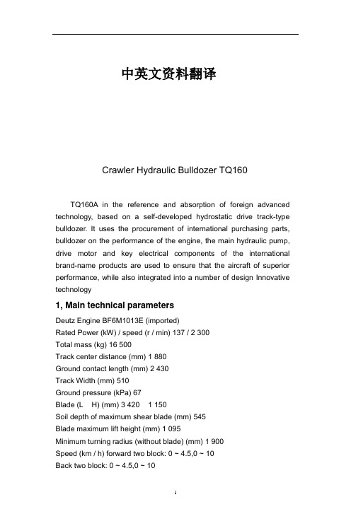
中英文资料翻译Crawler Hydraulic Bulldozer TQ160TQ160A in the reference and absorption of foreign advanced technology, based on a self-developed hydrostatic drive track-type bulldozer. It uses the procurement of international purchasing parts, bulldozer on the performance of the engine, the main hydraulic pump, drive motor and key electrical components of the international brand-name products are used to ensure that the aircraft of superior performance, while also integrated into a number of design Innovative technology1, Main technical parametersDeutz Engine BF6M1013E (imported)Rated Power (kW) / speed (r / min) 137 / 2 300Total mass (kg) 16 500Track center distance (mm) 1 880Ground contact length (mm) 2 430Track Width (mm) 510Ground pressure (kPa) 67Blade (L × H) (mm) 3 420 × 1 150Soil depth of maximum shear blade (mm) 545Blade maximum lift height (mm) 1 095Minimum turning radius (without blade) (mm) 1 900Speed (km / h) forward two block: 0 ~ 4.5,0 ~ 10Back two block: 0 ~ 4.5,0 ~ 102, the main structure and performance characteristics2.1 set axis units frameShown in Figure 1, sets the frame with swing shaft structure, which with the balance beam is connected via a dedicated articulated mechanism to fully meet the bulldozer work in Taiwan, the swing frame required; and racks through the fixed pivot independent of each other , pivot detachable structure, most of the weight machine passed directly to the frame through the pivot, thus greatly reducing the transmission of the bulldozer was at work, the impact and prolong the life of the transmission system; pendulum shaft structure Province frame to the traditional structure of the ramp platform support, simplified structure, improved processing technology, reduce production cost and increase rigidity; the final drive and sets the frame separately, without dismantling the case of Taiwan, a direct repair frame Final drive, easy maintenance.2.2 Work equipment controlsWorking. device control by the pilot control system, all actions Blade: upgrade, down, left and right tilt and float, complete with a handle and manipulate very labor-saving, light sensitive, accurate and reliable. Figure 2 shows the blade control handle. At the same time, the aircraft are also used with ripper pilot hydraulic control systems.2.3 Driving and parking brake control systemHydraulic proportional control servo drive control system, the system consists of a dedicated pilot gear pump oil, the forward, backward, left turn and driver-specific in situ hydrostatic steering performance focused on a handle, while the handle is integrated travel speakers , speed, and reversing alarm switch block, which greatly simplifies the control system running, so the driver can concentrate on work.When the control lever is in neutral position, the pump will cut off access to the variable ratio power servo control valve oil, zero displacement hydraulic pump, hydraulic motor lock, the vehicle can not walk, so as to achieve the purpose of the safety brake. To ensure the safety of vehicles, aircraft design is still a driven gear shaft safety brake for parking (or emergency parking brake), the brake is normally closed, when the engine stalled or moving the operating handle is in neutral position, the brakes closed under spring force, to achieve braking; and when the manipulation of moving the handle, the role of the control to open the brake fluid, so that bulldozers driving. Parking brake lever by the brake control and emergency brake button control, manipulation of any of them, can achieve braking.2.4 TransmissionShown in Figure 3, TQ160A bulldozers closed double-loopdouble-pump hydraulic system, driven by the engine double variable pump, piston-type variable hydraulic motor driven, hydrostatic drive system components, and finally tracked vehicle driven by the final drive and steering. Each side of the track system by an independent hydrostatic drive, so that bulldozers can easily achieve pivot turn, greatly enhanced the mobility of the bulldozers and work suitability.Our unique control system of the engine closed-loop constant power control system, the central controller (CPU) load based on the size of bulldozers at any time suffered moderator pump swashplate angle control drive system flow to the machine to automatically according to the size of external load adjust speed, fully meet the bulldozers at work on speed and power requirements to ensure the efficiency of machine, to prevent overloading the engine and can make full use of engine power.TQ160A bulldozer driven by electric motor two-block variable motor, the whole block forward and backward are the two to meet the needs of different conditions.2.5 Intelligent alarm systemTQ160A three bulldozers with complete intelligent alarm system, through the instrument panel meters, LED, buzzer and LCD monitors to keep it informed of the vehicle running all kinds of information, such as: engine temperature, oil pressure, hydraulic oil temperature, working hours, engine speed and battery charge and discharge; the sensors to collect information processed by the CPU through the liquid crystal display to determine a text or voice expressed in the form, such as thework of the solenoid valve opening, engine speed and the machine appears failure, etc.; The display can also work to select the operating mode of the engine.2.6 MaintenanceAs a result of hydrostatic transmission system, eliminating the torque converter drive bulldozers, power transmission, a central transmission, steering clutches and steering brakes and other components, greatly simplifying the whole structure, so that maintenance of the transmission system is convenient.In order to facilitate the hydraulic system pressure measurement, to help repair and maintenance, the aircraft pressure measurement using a centralized approach, all the measurement points are located in the left cabinets, open the box lid can see, very convenient. The aircraft left engine cover, left box spring cover support oil and gas are used, open save time and effort.2.7Modeling and machine vision drivers.Whole shape of beautiful and unique machine, the cab structure with six sides, so as to increase the door width of the cab, front blade to enhance the hydraulic cylinder, compared with the traditional style, greatly improved vision.2.8 configurationROPS / FOPS cab, straight tilting blade and the machine after the traction frame is a standard configuration. At the same time, users can use optional different angle blade, ripper, and heating and air conditioning.TQ160履带式全液压推土机TQ160A是在参考和吸收国外先进技术的基础上,自行研制开发的一种静液压驱动履带式推土机。
液压挖掘机的半自动控制系统毕业论文中英文资料对照外文翻译文献综述

液压挖掘机的半自动控制系统中英文资料对照外文翻译文献综述翻译部分1.英文原文Semi-automatic control system for hydraulic shovelHirokazu Araya),Masayuki KagoshimaMechanical Engineering Research Laboratory,Kobe Steel,Ltd.,Nishi-ku,Kobe Hyogo 651 2271,JapanAccepted 27 June 2000AbstractA semi-automatic control system for a hydraulic shovel has been ing this system,unskilled operators canoperate a hydraulic shovel easily and accurately.A mathematical control model of a hydraulic shovel with a controller wasconstructed and a control algorithm was developed by simulation.This algorithm was applied to a hydraulic shovel and itseffectiveness was evaluated.High control accuracy and high-stability performance were achieved by feedback plusfeedforward control,nonlinear compensation,state feedback and gainscheduling according to the attitude.q 2001 ElsevierScience B.V.All rights reserved.Keywords: Construction machinery;Hydraulic shovel;Feedforward;State feedback;Operation1.IntroductionA hydraulic shovel is a construction machinery that can be regarded as a large articulated robot. Digging and loading operations using this machine require a high level of skill,and cause considerable fatigue even in skilled operators.On the other hand, operators grow older,and the number of skilled operators has thus decreased.The situation calls for hydraulic shovels,which can be operated easily by any person w1 –5x. The reasons why hydraulic shovel requires a high level of skill are as follows.1.More than two levers must be operated simulta-neously and adjusted well in such operations.2.The direction of lever operations is different from that of a shovel’s attachment movement. For example,in level crowding by a hydraulic shovel,we must operate three levers ?arm,boom, bucket. simultaneously to move the top of a bucket along a level surface ?Fig.1..In this case,the lever operation indicates the direction of the actuator,but this direction differs from the working direction. If an operator use only one lever and other free-doms are operated automatically,the operation be-comes veryeasily.We call this system a semi-auto-matic control system.When we develop this semi-automatic control system,these two technical problems must be solved.1.We must use ordinary control valves for auto-matic control.2.We must compensate dynamic characteristics of a hydraulic shovel to improve the precision of control.Fig.1.Level crowding of an excavator and frame model of an excavator. We have developed a control algorithm to solve these technical problemsand confirm the effect of this control algorithm by experiments with actual hydraulic ing this control algorithm,we have completed a semi-automatic control system for hydraulic shovels.We then report these items.2.Hydraulic shovel modelTo study control algorithms,we have to analyze numerical models of a hydraulic shovel.The hy- draulic shovel,whose boom,arm,and bucket joints are hydraulically driven,is modeled as shown in Fig.2.The details of the model are described in the following.2.1.Dynamic model [6]Supposing that each attachment is a solid body, from Lagrange’s equations of motion,the following expressions are obtained:K 3 s m 3 1 g3g;and g s gravitational acceleration. u is the joint angle,t is the supply torque the attachment length,1 g iis the distance between the fulcrum and the center of gravity,m iis the mass of the attachment,I iis the moment of inertia around the center of gravity ?subscripts i s 1–3,mean boom, arm,and bucket,respectively..2.2.Hydraulic modelEach joint is driven by a hydraulic cylinder whose flow is controlled by a spool valve,as shown in Fig.3.We can assume the following:1.The open area of a valve is proportional to the spool displacement.2.There is no oil leak.3.No pressure drop occurs when oil flows throughpiping.H.Araya,M.Kagoshimar Automation in Construction 10 (2001) 477–486 479Fig.2.Model of hydraulic shovel.4.The effective sectional area of the cylinder is the same on both the head and the rod sides. In this problem,for each joint,we have the followingequation from the pressure flow character-stics of the cylinder:时;where,A is effective cross-sectional area of cylin-der;h i s cylinder length;X is spool displacement;Ps i s supply pressure;P1 is cylinder head-side pres-sure;P 2 i s cylinder rod-side pressure;Vi s oilvol-ume in thecylinder andpiping;B is spoolwidth; gsoildensity;KsbulkFig.3.Model of hydraulic cylinder and valve.modulus of oil;and cs flow coefficient.2.3.Link relationsIn the model shown in Fig.1,the relation be-tween the cylinder length change rate and the attach-ment rotational angular velocity is given as follows:?1. boom2.4.Torque relations From the link relations of Section 2.3,the supply torque t is given as follows,taking cylinder friction I into consideration: Where,C ciis the viscous friction coefficient and Fi is kinetic frictional force of a cylinder2.5.Response characteristics of the spool Spool action has a great effect on control charac-teristics.Thus,we are assuming that the spool hasthe following first-order lag against the reference input.iis the reference input of spool dis- placement and Ts piis a time constant.3.Angle control systemAs shown in Fig.4,the angle u is basically controlled to follow the reference angle ug by posi-tion feedback.In order to obtain more accuratecontrol,nonlinear compensation and state feedback are added to theposition feedback.We will discuss details of these algorithms as follows. 3.1.Nonlinear compensationIn the ordinary automatic control systems,new control devices such as servo valves are used.In our semi-automatic system,in order to realize the coexistence of manual and automatic operations,we must use the main control valves,which are used in manual operation.In these valves,the relation between spool displacement and open area is nonlinear. Then,in automatic operation,using this relation,the spool displacement is inversely calculated from the required open area,and the nonlinearity is compen- sated ?Fig.5..Fig.4.Block diagram of control system ?u..H.Araya,M.Kagoshimar Automation in Construction 10 (2001) 477–486 481Fig.5.Nonlinear compensation.3.2.State feedbackBased on the model discussed in Section 2,if thedynamic characteristics forboom angle control are linearized in the vicinity of a certain standard condition ?spool displacement X10,cylinder differential pressure P,and boom angle u.,the closed-looptransfer function can be expressed byThis system has a comparatively small coefficient a1so the response is oscillatory.For instance,if in our large SK-16 hydraulic shovel,X 10is 0,the coefficients are given as a s 2.7=102.Addingthe accelerationfeedback of gain Ka,to this ?the upper loop in Fig.4.,the closed loop transfer function is given as Adding this factor,the coefficient of s2 becomes larger,thus,the system becomes stable.In this way,acceleration feedback is effective in improving the response characteristics.However,it is generally difficult to detect acceleration accurately.To overcome this difficulty,cylinder force feedback was applied instead of acceleration feedback ?the lower loop in Fig.4..In this case,cylinder force is calculated from detected cylinder pressure and filtered in its lower-frequency portion w 7,8x.This is called pressure feedback.4.Servo control systemWhen one joint is manually operated and another joint is controlled automatically to follow the manual operation,a servo control system must be required. For example,as shown in Fig.6,in the level crowding control,the boom is controlled to keep the arm end height Z ?calculated from u and u .to reference Zr.In order to obtain more accurate control,the following control actions are introduced.482H.Araya,M.Kagoshimar Automation in Construction 10 (2001) 477–486Fig.6.Block diagram of control system ?Z..4.1.Feedforward control Calculating Z from Fig.1,we obtain Differentiating both sides of Eq.?8. with respect to time,we have the following relation, The first term of the right-hand side can be taken as the expression ?feedback portion. to convert Z˙ to u˙,and the second term of the right-hand side is the expression ?feedforward portion. to calculate how much u should be changed when u is changed 1 2 manually.Actually,u˙ is determined using the difference2 value of Du.To optimizehe feedforward rate,feedforward gain K ffis tunned. There may be a method to detect and use the arm operating-lever condition ?i.e.angle. instead of arm angular velocity,since the arm is driven at an angular velocity nearly proportional to this lever condi-tion.4.2.Adapti?e gain scheduling according to the attitude In articulated machines like hydraulic shovels,dynamic characteristics are greatly susceptible to the attitude.Therefore,it is difficult to control the machine stably at all attitudes with constant gain.To solve this problem,the adaptive gain scheduling according to the attitude is multiplied in the feedbackloop ?Fig.6..As shown in Fig.7,the adaptive gain KZ or K u .is characterized as a function of two variables,u X and Z.u X 2 2means how the arm is extended,and Z means the height of the bucket.5.Simulation resultsThe level crowding control was simulated byapplying the control algorithm described in Section 4 to the hydraulic shovel model discussed in Section 2.In the simulation,our large SK-16 hydraulic shovel was employed..Fig.8 shows one of the results.Five seconds after the control started,load disturbanceH.Araya,M.Kagoshimar Automation in Construction 10 (2001) 477–486 483Fig.7.Gain scheduling according to the attitude. was applied stepwise.Fig.9shows the use of feedforward control can reduce control error.6.ConclusionsThis paper has shown that combining state feedback and feedforward controls makes it possible toaccurately control the hydraulic shovel,and also showed that nonlinear compensation makes it possible to use ordinary control valves for automatic controls.The use of these control techniques allows even unskilled operators to operate hydraulic shovels easily and accurately.We will apply these control techniques to other construction machinery such as crawler cranes,and improve the conventional construction machinery to the machines which can be operated easily byanyone.2. 中文译文液压挖掘机的半自动控制系统Hirokazu Araya ,Masayuki Kagoshima 日本机械工程研究实验室Kobe Steel, Ltd., Nishi-ku, Kobe Hyogo 651 2271,2000年7月27日摘要开发出了一种应用于液压挖掘机的半自动控制系统。
汽车式起重机液压系统外文文献翻译中英文

外文文献翻译(含:英文原文及中文译文)文献出处:K Tanizumi. Truck Crane Hydraulic System: Technical Status and Development Trend [J]. Advanced Materials Research, 2015, 310-319中文译文汽车式起重机液压系统: 技术现状与发展趋势K Tanizumi1行业背景1.1工程汽车起重机的发展趋势近20年世界工程起重机行业发生了很大变化。
RT(越野轮胎起重机) 和AT(全地面起重机) 产品的迅速发展,打破了原有产品与市场格局,在经济发展及市场激烈竞争冲击下, 导致世界市场进一步趋向一体化。
为与RT 和AT 产品抗衡, 汽车起重机新技术、新产品也在不断发展。
近年来汽车起重机在英、美等国市场的复兴,使人们对汽车起重机产生新的认识。
几年前某些工业界人士曾预测, RT 和AT 产品的兴起将导致汽车起重机的衰退。
日本汽车起重机在世界各地日益流行,以及最近格鲁夫、特雷克斯、林克.贝尔特、德马泰克等公司汽车起重机的产品进展, 已向上述观念提出挑战。
随着工程起重机各机种间技术的相互渗透与竞争,汽车起重机会在世界市场中继续占有一席之地。
国外工程起重机从整体情况分析, 领先国内10~20年(不同类型产品有所不同) 。
随着国外经济发展速度趋于平稳,工程起重机向智能、高性能、灵活、适应性强、多功能方向发展。
25t 以下基本上不生产,产品向高附加值、大吨位发展, 住友建机、多田野和加藤公司曾于1989年相继推出360t 汽车起重机。
住友建机在90年代开发出80t ~250t 共4种AT 产品。
多田野也在90年代相继推出100t ~550t 共6种特大型AT 产品。
加藤公司则研制成NK5000型500t 汽车起重机。
行业配套也与国内有所不同:(1)下车主要是300kW 以上柴油大功率发动机,与之配套的液力变矩器和自动换档变速箱、12吨级驱动转向桥及越野轮胎。
液压系统安装中的污染控制外文文献翻译、中英文翻译

外文资料In hydraulic system installment contamination controlPaper abstract:The hydraulic system pollution is a hydraulic pressure breakdown main reason, after in order to guarantee the installment the hydraulic system to be able the security, the reliable movement, in view of the hydraulic system installment proposed a series of concrete measures, achieve in the construction process contamination control1OutlineThe technology of hydraulic transmission gets swift and violent development after emerging in the 18th century. Today, the apparatus of hydraulic transmission is widely used in all trades and professions, reflect on the modernized large-scale production line particularly abundantly. The steel hot-rolled H section steel production line of horse, the volume 54 kL of the hydraulic fuel tank, 38 hydraulic motors, of different specifications hydraulic jar up to 717, only the hydraulic pipeline is as long as more than 20,000 meters.The technology of hydraulic transmission has its advantage that can't be compared, this is the main reason that it can develop rapidly , meanwhile, the apparatus of hydraulictransmission has its fragiles aspects, among them the ability to resist pollution is low is an outstanding weakness . According to the records of relevant materials, the hydraulic trouble has 70- 8 to cause by the pollution of fluid. It must keep the systematic cleanness to guarantee the normal , reliable operation of the hydraulic system.2 Danger and reason that the system pollutesPollutant sneak into behind the system can accelerate hydraulic wearing and tearing of part , grind , decrease , burn even destroy or cause the movements of the valve not to work or cause the noising. The pollutant will stop up the throttle hole of the hydraulic component or reduce expenditure in the chink , change the working performance of the hydraulic system, cause movements to lack proper care even not work at all, produce and act and cause the accident by mistake . The dust particle will accelerate the damage of the seal in the hydraulic jar, the superficial one is strained in the tube of jar, make it increase not to let out, thrust insufficient or movements are unstable, creep, the pace drop, produce unusual sound and vibration. Also may cause filter screen stop up, hydraulic pump suck oil to be difficult, go back oil to be smooth producing angry losing , vibration and noise, will puncture the filter screen becauseresistance is too big while stopping up seriously , totally lose the function of filtering, cause the hydraulic and systematic vicious circle.The reason why the system pollutes is numerous, according to producing mechanism in pollution, divided into 2 kinds:(1)Pollutant made , hidden in the installation in the system.(2)Pollution that is produced in the course of system work. Obviously, pollutant made , hidden in the installation of the system is mostly smear metal , burr , molding sand , coating , abradant , solid particle of welding dreg , rust one and dust etc., they relatively loud in danger in system, must strengthen management at this stage , control pollution, guarantee the hydraulic system after installing can run safly and reliably .3Pollution control in the hydraulic system is made and installed3.1 Pollution control that the hydraulic part is processedThe processing of the hydraulic part generally demands to adopt the law of " processes wetly ", all processing processes want , drip , add , lubricate liquid or cleaner , so as to ensure surface process quality.3.2 Washing of hydraulic component , partBefore the new hydraulic pressure one is assembled, theold hydraulic pressure one can be used through washing after being polluted, should accomplish the following several points in the cleaning process.1)Hydraulic pressure pieces of disassembly and assembly , wash , should go on among clean room to accord with the national standard, if there is operating room of conditions that can be filled and pressed, make the indoor pressure higher than outdoors, prevent the atmospheric dust from polluting. If restrain terms from, should operate one to isolate alone even , seldom allow hydraulic pressure assembly one and machining of one sometimes in the same room among the pincers workers, forbid decomposing and assembling the hydraulic pressure one in the open , in warehouse of sometimes the shed , incidental absolutely .The hydraulic pressure of disassembly and assembly is a hour, attenbant should wear fiber difficult work clothes , work cap that come off, in case fiber, dust, hair, scurf,etc. scattered to fall into hydraulic system cause artificial to pollute. Forbid operating one and smoking , taking food inside.2)The hydraulic pressure one should go on in washing the platform to wash special-purposly, if limited by the condition , guarantee cleanness degree of the temporary workingbench .3)The cleaner allows to use the kerosene , petrol and use the same hydraulic oil of trade mark of oil with hydraulic system work.4)The part after washing is forbidden to be polished with the cotton , flax , silk and chemical fibre manufactured goods, prevent the fiber coming off from polluting the system. Forbid with leather tiger to part blast air (leather tiger have dust particle ) too, can dry up the part with the clean and dry compressed air if necessary.5)Part wash , forbid , put in land , cement ground , floor , pincers worker platform and assemble workingbench directly, and should put into container with cover , pour into the hydraulic oil .6)Have already washed but the part that wouldn't be assembled should be put into and antirusted and saved in the oil, moist area and season especially should pay attention to antirusting.3.3 Pollution control in a piece of transportation of hydraulic pressureIn hydraulic component , package transportation , should pay attention to the dustproof , rain-proof , especially hydraulic pressure piece of marine transportation want , fight withrain-proof paper or plastic wrapping paper kind to pack to transport for long-distance, put right amount of desiccant , does not allow rainwater , sea water to be exposed to the hydraulic pressure one . Before casing and after unpacking , should check carefully whether the oil mouth is stopped up , stopped up firm with the stopper, to receive slight oil mouth of pollution take remedy in time , must decompose , wash to the hydraulic pressure one with serious pollution moreover.3.4 The fuel tank refuelsThe fuel tank must be checked its internal cleanness degree before fuel-injection, the one not up to standard will be cleared up ; Cleanness degree that the fluid should be examined it before being joined; Must not allow to pour into the oil the fuel tank directly through filtering at the time of fuel-injection.3.5 The system resumesAfter the system is pickled, developed, can link all components , pipelines on request the job return circuit . This course should pay special attention to being in charge of connecting and keeping a public place clean , finish joining , , try hard to avoid dismantling, should pay attention to , wrap up , well , guarantee , in charge of , connect with clean cloth if necessary , calibre pollute.4 SummaryHydraulic systematic pollution control runs through in the whole construction course, require operators every step should consider the measure of keeping a public place clean , reduce system pollute , guarantee the hydraulic system after constructing can run safly , reliably to the greatest extent.中文译文液压系统安装中的污染控制论文摘要:液压系统污染是液压故障的一个主要原因,为了确保安装后的液压系统能够安全、可靠运行,针对液压系统安装提出一系列具体措施,以达到施工过程中的的污染控制。
液压系统污染控制与液压系统故障
液压系统污染控制与液压系统故障摘要:液压系统故障的发生,在很大程度上取决于液压系统中元件的耐污染能力和系统油液的污染状况,通过控制液压系统的污染程度,就可以保证液压系统的可靠性,降低液压系统故障发生率。
主题词液压系统污染控制故障Abstract: the hydraulic system of failure, depends to a great extent on the components of hydraulic system and the system pressure oil pollution resistant ability of pollution condition, through the control hydraulic system level of pollution, can guarantee the reliability of the hydraulic system, reduce the incidence of hydraulic system failure.Keywords hydraulic system pollution control fault中图分类号:{X323}文献标识码:A文章编号:液压传动是以液压油为工作介质进行能量转换和动力传递的,它具有传递能量大、布局容易、结构紧凑、换向方便、转动平稳、均匀、容易完成复杂动作等优点,因而广泛应用于工程机械领域。
对于液压系统,当其使用条件满足规定条件时,就可以实现下列两个目标:(1)使无故障工作的持续时间保持在规定的时间内;(2)在上述时间内完成规定的功能。
一旦使用条件不能满足规定的条件,液压系统的可靠性则大大降低,其可靠性就变成了“液压系统、元件等的功能在时间上的稳定程度和稳定特性”,液压系统实现可靠性的规定条件当然很多,但最重要的一条就是液压系统的污染程度必须控制在关键元件的污染耐受度之内。
- 1、下载文档前请自行甄别文档内容的完整性,平台不提供额外的编辑、内容补充、找答案等附加服务。
- 2、"仅部分预览"的文档,不可在线预览部分如存在完整性等问题,可反馈申请退款(可完整预览的文档不适用该条件!)。
- 3、如文档侵犯您的权益,请联系客服反馈,我们会尽快为您处理(人工客服工作时间:9:00-18:30)。
外文资料In hydraulic system installment contamination controlPaper abstract:The hydraulic system pollution is a hydraulic pressure breakdown main reason, after in order to guarantee the installment the hydraulic system to be able the security, the reliable movement, in view of the hydraulic system installment proposed a series of concrete measures, achieve in the construction process contamination control1OutlineThe technology of hydraulic transmission gets swift and violent development after emerging in the 18th century. Today, the apparatus of hydraulic transmission is widely used in all trades and professions, reflect on the modernized large-scale production line particularly abundantly. The steel hot-rolled H section steel production line of horse, the volume 54 kL of the hydraulic fuel tank, 38 hydraulic motors, of different specifications hydraulic jar up to 717, only the hydraulic pipeline is as long as more than 20,000 meters.The technology of hydraulic transmission has its advantage that can't be compared, this is the main reason that it can develop rapidly , meanwhile, the apparatus of hydraulictransmission has its fragiles aspects, among them the ability to resist pollution is low is an outstanding weakness . According to the records of relevant materials, the hydraulic trouble has 70- 8 to cause by the pollution of fluid. It must keep the systematic cleanness to guarantee the normal , reliable operation of the hydraulic system.2 Danger and reason that the system pollutesPollutant sneak into behind the system can accelerate hydraulic wearing and tearing of part , grind , decrease , burn even destroy or cause the movements of the valve not to work or cause the noising. The pollutant will stop up the throttle hole of the hydraulic component or reduce expenditure in the chink , change the working performance of the hydraulic system, cause movements to lack proper care even not work at all, produce and act and cause the accident by mistake . The dust particle will accelerate the damage of the seal in the hydraulic jar, the superficial one is strained in the tube of jar, make it increase not to let out, thrust insufficient or movements are unstable, creep, the pace drop, produce unusual sound and vibration. Also may cause filter screen stop up, hydraulic pump suck oil to be difficult, go back oil to be smooth producing angry losing , vibration and noise, will puncture the filter screen becauseresistance is too big while stopping up seriously , totally lose the function of filtering, cause the hydraulic and systematic vicious circle.The reason why the system pollutes is numerous, according to producing mechanism in pollution, divided into 2 kinds:(1)Pollutant made , hidden in the installation in the system.(2)Pollution that is produced in the course of system work. Obviously, pollutant made , hidden in the installation of the system is mostly smear metal , burr , molding sand , coating , abradant , solid particle of welding dreg , rust one and dust etc., they relatively loud in danger in system, must strengthen management at this stage , control pollution, guarantee the hydraulic system after installing can run safly and reliably .3Pollution control in the hydraulic system is made and installed3.1 Pollution control that the hydraulic part is processedThe processing of the hydraulic part generally demands to adopt the law of " processes wetly ", all processing processes want , drip , add , lubricate liquid or cleaner , so as to ensure surface process quality.3.2 Washing of hydraulic component , partBefore the new hydraulic pressure one is assembled, theold hydraulic pressure one can be used through washing after being polluted, should accomplish the following several points in the cleaning process.1)Hydraulic pressure pieces of disassembly and assembly , wash , should go on among clean room to accord with the national standard, if there is operating room of conditions that can be filled and pressed, make the indoor pressure higher than outdoors, prevent the atmospheric dust from polluting. If restrain terms from, should operate one to isolate alone even , seldom allow hydraulic pressure assembly one and machining of one sometimes in the same room among the pincers workers, forbid decomposing and assembling the hydraulic pressure one in the open , in warehouse of sometimes the shed , incidental absolutely .The hydraulic pressure of disassembly and assembly is a hour, attenbant should wear fiber difficult work clothes , work cap that come off, in case fiber, dust, hair, scurf,etc. scattered to fall into hydraulic system cause artificial to pollute. Forbid operating one and smoking , taking food inside.2)The hydraulic pressure one should go on in washing the platform to wash special-purposly, if limited by the condition , guarantee cleanness degree of the temporary workingbench .3)The cleaner allows to use the kerosene , petrol and use the same hydraulic oil of trade mark of oil with hydraulic system work.4)The part after washing is forbidden to be polished with the cotton , flax , silk and chemical fibre manufactured goods, prevent the fiber coming off from polluting the system. Forbid with leather tiger to part blast air (leather tiger have dust particle ) too, can dry up the part with the clean and dry compressed air if necessary.5)Part wash , forbid , put in land , cement ground , floor , pincers worker platform and assemble workingbench directly, and should put into container with cover , pour into the hydraulic oil .6)Have already washed but the part that wouldn't be assembled should be put into and antirusted and saved in the oil, moist area and season especially should pay attention to antirusting.3.3 Pollution control in a piece of transportation of hydraulic pressureIn hydraulic component , package transportation , should pay attention to the dustproof , rain-proof , especially hydraulic pressure piece of marine transportation want , fight withrain-proof paper or plastic wrapping paper kind to pack to transport for long-distance, put right amount of desiccant , does not allow rainwater , sea water to be exposed to the hydraulic pressure one . Before casing and after unpacking , should check carefully whether the oil mouth is stopped up , stopped up firm with the stopper, to receive slight oil mouth of pollution take remedy in time , must decompose , wash to the hydraulic pressure one with serious pollution moreover.3.4 The fuel tank refuelsThe fuel tank must be checked its internal cleanness degree before fuel-injection, the one not up to standard will be cleared up ; Cleanness degree that the fluid should be examined it before being joined; Must not allow to pour into the oil the fuel tank directly through filtering at the time of fuel-injection.3.5 The system resumesAfter the system is pickled, developed, can link all components , pipelines on request the job return circuit . This course should pay special attention to being in charge of connecting and keeping a public place clean , finish joining , , try hard to avoid dismantling, should pay attention to , wrap up , well , guarantee , in charge of , connect with clean cloth if necessary , calibre pollute.4 SummaryHydraulic systematic pollution control runs through in the whole construction course, require operators every step should consider the measure of keeping a public place clean , reduce system pollute , guarantee the hydraulic system after constructing can run safly , reliably to the greatest extent.中文译文液压系统安装中的污染控制论文摘要:液压系统污染是液压故障的一个主要原因,为了确保安装后的液压系统能够安全、可靠运行,针对液压系统安装提出一系列具体措施,以达到施工过程中的的污染控制。