派克PARKER 马达
派克PARKER液压元件与力士乐REXROTH液压元件对照表
Rexroth 型号 无此型号 无此型号 无此型号 无此型号 A4VSO-40-DR 无此型号 无此型号 A4VSO-71-DR 无此型号 A4VSO-125-DR A4VSO-180-DR A4VSO-250-DR
2
F11 F12 系列定量柱塞泵 Parker 型号 F11-014-MF-SN-K F11-019-MF-SN-K F12-030-MF-IH-K F12-040-MF-IH-K F12-060-MF-IH-K F12-060-MF-IH-K F12-080-MF-IH-K F12-080-MF-IH-K F12-110-MF-IH-K F12-110-MF-IH-K F11-150-MF-SN-K F11-250-MF-SN-K
Rexroth 型号 DBETR-1X/…… DBEM10-5X/…… DBEM20-5X/…… DBEM30-5X/…… 4WRE6E/…… 4WRE6W/…... 4WRA10E/…… 4WRA10EA/…… 4WRZ10E/…… 4WRZ10W/… 4WRZ16E/…… 4WRZ16W/…… 4WRZ25E/… 4WRZ25W/… 4WRZ32E/…… 4WRZ32W/……
11
叠加式单向阀
Parker 型号 CM2PP CM2AA CM2TT CM2BB CM3PP CM3AA CM3TT CM3BB
Rexroth 型号 Z1S6PA-2X/ Z1S6C1-2X/ Z1S6T1-2X/ Z1SDA-2X/ Z1S10PA-2X/ Z1S10C1-2X/ Z1S10T1-2X/ Z1S10DA-2X/
Rexroth 型号 无此型号 无此型号 A2FM-28/61-W-P-B A2FM-45/61-W-P-B A2FM-56/61-W-P-B A2FM-63/61-W-P-B A2FM-80/61-W-P-B A2FM-90/61-W-P-B A2FM-107/61-W-P-B A2FM-125/61-W-P-B 无此型号 无此型号
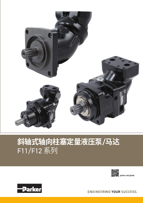
斜轴式轴向柱塞定量液压泵 马达 F11 F12 系列说明书
/马达/pmde2Parker HannifinPump & Motor Division Europe Trollhättan, Sweden液压泵/马达F11/F12 系列样本 MSG30-8249/CN换算系数1 kg ..............................................................................2.20 lb 1 N .............................................................................0.225 lbf 1 Nm .....................................................................0.738 lbf ft 1 bar ..........................................................................14.5 psi 1 l .................................................................0.264 US gallon 1 cm 3 ...................................................................0.061 cu in 1 mm ..........................................................................0.039 in 1°C ..........................................................................5/9(°F-32)1 kW ............................................................................1.34 hp换算系数1 lb ............................................................................0.454 kg 1 lbf .............................................................................4.448 N 1 lbf ft .....................................................................1.356 Nm 1 psi ..................................................................0.068948 bar 1 US gallon .................................................................3.785 l 1 cu in .................................................................16.387 cm 31 in ............................................................................25.4 mm 1°F .........................................................................9/5°C + 321 hp ........................................................................0.7457 kW扭矩 (M)M =[Nm]液压马达基本公式流量 (q)q = [l/min]功率 (P) P = [kW]D x n1000 x ηv D x Δp x ηhm63q x Δp x ηt600D - 排量 [cm 3/rev] n - 轴转速 [rpm] ηv - 容积效率Δp - 进油口和出油口之间的压差 [bar] ηhm - 机械效率 ηt - 总效率(ηt = ηv x ηhm )扭矩 (M)M = [Nm]液压泵基本公式流量 (q)q = [l/min]功率 (P)P = [kW]D x n x ηv1000 D x Δp63 x ηhmq x Δp600 x ηtD - 排量 [cm 3/rev] n - 轴转速 [rpm] ηv - 容积效率Δp - 进油口和出油口之间的压差 [bar] ηhm - 机械效率 ηt - 总效率(ηt = ηv x ηhm )销售条件本样本中的各种产品均由派克汉尼汾公司及其子公司和授权经销商销售。
派克液压齿轮马达型号参数
派克液压齿轮马达型号参数派克液压齿轮马达是一种非常重要的液压传动元件,广泛应用于各种工业设备、机械以及农业机械等领域。
在选择和使用液压齿轮马达时,了解其型号参数是非常必要的。
本文将详细介绍派克液压齿轮马达的型号参数,包括压力范围、流量范围、排量、转速、重量等方面,以便更好的选择和使用派克液压齿轮马达。
一、型号参数之压力范围压力范围是指液压齿轮马达可以承受的最大压力,通常以Mpa为单位。
派克液压齿轮马达的压力范围在13.8Mpa 至20.7Mpa之间,其具体数值取决于不同型号的液压齿轮马达。
在选择液压齿轮马达时,需要根据实际工作环境和使用要求选择合适的压力范围,以确保液压齿轮马达的正常使用。
二、型号参数之流量范围流量范围是指液压齿轮马达在单位时间内传递的液体体积,通常以升/分钟为单位。
派克液压齿轮马达的流量范围在49升/分钟至955升/分钟之间,其具体数值也取决于不同型号的液压齿轮马达。
在选择液压齿轮马达时,需要根据实际工作环境和使用要求选择合适的流量范围,以确保液压齿轮马达的正常使用。
三、型号参数之排量排量是指液压齿轮马达每转一圈所输出的液体体积,通常以毫升/转为单位。
派克液压齿轮马达的排量在4毫升/转至32毫升/转之间,其具体数值也取决于不同型号的液压齿轮马达。
在选择液压齿轮马达时,需要根据实际工作环境和使用要求选择合适的排量,以确保液压齿轮马达的正常使用。
四、型号参数之转速转速是指液压齿轮马达在单位时间内的转动次数,通常以rpm为单位。
派克液压齿轮马达的转速在800rpm至4000rpm之间,其具体数值也取决于不同型号的液压齿轮马达。
在选择液压齿轮马达时,需要根据实际工作环境和使用要求选择合适的转速,以确保液压齿轮马达的正常使用。
五、型号参数之重量重量是指液压齿轮马达本身的重量,通常以千克为单位。
派克液压齿轮马达的重量在1.5千克至82千克之间,其具体数值也取决于不同型号的液压齿轮马达。
在选择液压齿轮马达时,需要根据实际工作要求选择合适的重量,以确保安装过程的顺利进行。
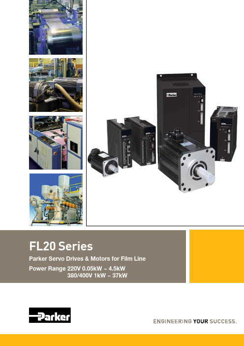
浦克尔(Parker)电机驱动系列FL20系列产品说明说明书
Power Range 2Parker FL20 SeriesServo drive · motorWARNING — USER RESPONSIBILITYFAILURE OR IMPROPER SELECTION OR IMPROPER USE OF THE PRODUCTS DESCRIBED HEREIN OR RELATED ITEMS CAN CAUSE DEATH, PERSONAL INJURY AND PROPERTY DAMAGE.• This document and other information from Parker-Hannifi n Corporation, its subsidiaries and authorized distributors provide product or system options for further investigation by users having technical expertise.• The user, through its own analysis and testing, is solely responsible for making the fi nal selection of the system and components and assuring that all performance, endurance, maintenance, safety and warning requirements of the application are met. The user must analyze all aspects of the application, follow applicable industry standards, and follow the information concerning the product in the current product catalog and in any other materials provided from Parker or its subsidiaries or authorized distributors.• To the extent that Parker or its subsidiaries or authorized distributors provide component or system options based upon data or specifi cations provided by the user, the user is responsible for determining that suchdata and specifi cations are suitable and suffi cient for all applications and reasonably foreseeable uses of the components or systems.Parker FL20 SeriesServo drive · motorFL20 Servo DriveDrive overview (5)Technical characteristics (6)Drive component (8)Terminal details (10)Wiring diagram (13)Connection to Peripheral Devices (14)Typical main circuit wiring (15)Ordering code - Drive (16)Drive dimensions (18)Servo MotorServo motor overview (22)Ordering code - Motor (23)Technical characteristics (24)Motor dimensions (27)Accessories (32)Parker FL20 Series Servo drive · motorGlobal Product DesignParker Hannifin has more than 40 years experience in the design and manufacturing of drives, controls, motors and mechanical products. With dedicated global productdevelopment teams, Parker draws on industry-leading technological leadership and experience from engineering teams in Europe, North America and Asia.Local Application Expertise Parker has local engineering resources committed to adapting and applying our current products and technologies to best fit our customers’ needs.Manufacturing to Meet Our Customers’ NeedsParker is committed to meeting the increasing service demands that our customers require to succeed in the global industrial market. Parker’s manufacturing teams seek continuous improvement through the implementation of lean manufacturing methods throughout the process. We measure ourselves on meeting our customers’ expectations of quality and delivery, not just our own. In order to meet these expectations, Parker operates and continues to invest in ourmanufacturing facilities in Europe, North America and Asia.Parker HannifinThe global leader in motion and control technologiesWuxi, China Littlehampton, UK Charlotte NC, USA Chennai, IndiaJangan, KoreaParker provides sales assistance and local technical support through a network of dedicated sales teams and authorized technical distributors.For contact information, please refer to the Sales Offices on the back cover of this document or visit Electromechanical Worldwide Manufacturing Locations EuropeLittlehampton, United Kingdom Dijon, FranceOffenburg, Germany Filderstadt, Germany Milan, Italy AsiaWuxi, China Jangan, Korea Chennai, IndiaNorth AmericaRohnert Park, California Irwin, PennsylvaniaCharlotte, NorthCarolina NewUlm, MinnesotaParker FL20 SeriesServo drive · motorOverviewDescriptionFL20-S Series Servo Drives is a high performance drive particularly suitable for Film Line and similarapplications. It has a 1.2kHz frequency response with a full closed loop functionality. The feedback options are incremental encoder, absolute encoder and resolver.The FL20-S has in-built RS485/232 port for PC monitoring. It also has CANopen and EtherCATcommunication as options. The Parker PAC controller with its EtherCAT communication can be used as a complete solution for applications that need a controller as well as servo drives and motors.FL20C is the in built EtherCAT version of the FL20S. The I/Os are optimized as most of the commands would be through the EtherCAT communication.Features• Flexibility• Full closed loop control or multi-position control or interrupted position control • Gantry synchronization • Gain switchingFaster• Frequency response 1.2kHz • Dual-core processors • 23-bit absolute encoderPowerful• Built-in PLC Function• Pulse command Frequency up to 4Mhz • RS485/232, CANopen, EtherCAT• RS485/232 interface connected to PC SoftwareFL20 series Servo Drives for Film Line ApplicationsTechnical CharacteristicsParker FL20 SeriesServo drive · motorTechnical CharacteristicsFL20-S Servo Drive SpecificationsParker FL20 SeriesServo drive · motor Technical CharacteristicsFL20-C Servo Drive SpecificationsParker FL20 Series Servo drive · motorDrive ComponentInput Signal for FL20-S DrivesCharging IndicatorThe LED will light up when incoming poweris given. The DC Link capacitors will retain charge for some time even if power is turnedoff. Do not attempt to touch the power terminals as long as this LED is ‘ON”.Main Power InputOperator PanelSerial Communication Port (CN1)PC, PLC, CNC and other host controllerEncoder Interface (CN2)Connected with the servo motorInput and output signal (CN3)Command input, the monitor signal output terminal.Ground Connection.Must connect to ground at all times to avoid electric shock.Control Power InputBraking resistor connectionDC Reactor ConnectionServo Motor Connection1) 2connected power supply.2) 3forbidden to connect.1 phase 220V .Parker FL20 Series Servo drive · motorDrive ComponentInput Signal for FL20-C DrivesThe LED will light up when incoming poweris given. The DC Link capacitors will retain charge for some time even if power is turnedoff. Do not attempt to touch the power terminals as long as this LED is ‘ON”.Main Power InputOperator PanelSerial Communication Port (CN1)PC, PLC, CNC and other host controllerEncoder Interface (CN2)Connected with the servo motorInput and output signal (CN3)Command input, the monitor signal output terminal.Ground Connection.Must connect to ground at all times to avoid electric shock.Control Power InputBraking resistor connectionDC Reactor ConnectionServo Motor Connection1) 2connected power supply.2) 3forbidden to connect.1 phase 220V .Parker FL20 Series Servo drive · motorCN2 Terminal DefinitionFigure: From the wire side to drive side lookFigure: From the wire side to drive side lookTerminal DetailsCN1 Terminal DefinitionFigure: CN1 terminal definition (from the wire side to drive side view)Parker FL20 Series Servo drive · motorTerminal DetailsCN3 Terminal Definition for FL20-S Drives12Parker FL20 Series Servo drive · motorOther SignalCommunication PortTerminal DetailsCN3 Terminal Definition for FL20-C DrivesParker FL20 SeriesServo drive · motor Wiring diagramConnected to the shell1314Parker FL20 Series Servo drive · motor伺服电机PC ,PLC ORcommunication Servo motorConnection to Peripheral Devices(1 phase 220V, only L1 and L3 should be connected.)15Parker FL20 Series Servo drive · motorTypical main circuit wiringFor 220V servo driveFor 380V servo driveNote)For 220V input servo drive, L1C and L2C should be connected to power supply.For 220V single phase connect to L1 and L3.For 380V input servo drive, L1C and L2C are forbidden to connectPanel16Parker FL20 Series Servo drive · motorOrdering CodeFL20-S Series DriveNote)-EtherCAT, CANopen communication cards1.0kW, M2 Frame 152 T3 M2 1.5kW, M2 Frame 202 T3 M32kW, M3 Frame 302 T3 M33kW, M3 Frame 452 T3 M3 4.5kW, M3 Frame 552 T3 M3 5.5kW, M3 Frame 752 T3 MM47.5kW, MM4 Frame 113 T3 MM411kW, MM4 Frame 153 T3 M415kW, M4 Frame 183 T3 M518kW, M5 Frame 223 T3 M522kW, M5 Frame 303 T3 M630kW, M6 Frame 373 T3 M637kW, M6 FrameB3Built in Brake Unit + Dynamic Brake Note) - F or build in and external resistors details please 48 x 175 x 195B3(no braking resister)M275 x 175 x 195B1, B3M3100 x 203 x 218B1, B3M3(5.5kW)100 x 203 x 218B1MM4150 x 336 x 203B1(no braking resister)M4185 x 380 x 215B1(no braking resister)M5210 x 420 x 215B1(no braking resister)M6268.4 x 498 x 234B1(no braking resister)Note)- Specification subject to change without notice.Optional Communication CardParker FL20 SeriesServo drive · motor Ordering CodeFL20-C Series Drive202 T3 M32kW, M3 Frame 302 T3 M33kW, M3 Frame 452 T3 M3 4.5kW, M3 Frame 552 T3 M3 5.5kW, M3 Frame 752 T3 MM47.5kW, MM4 Frame 113 T3 MM411kW, MM4 Frame 153 T3 M415kW, M4 Frame 183 T3 M518kW, M5 Frame 223 T3 M522kW, M5 Frame 303 T3 M630kW, M6 Frame 373 T3 M637kW, M6 Frame B3Built-in Brake Unit + Dynamic Brake Note)- F or build in and external resistors details pleaseM148 x 175 x 195resistor)M275 x 175 x 195B1, B3M3100 x 203 x 218B1, B3M3(5.5kW)100 x 203 x 218B1MM4150 x 336 x 203B1(No built-in brakingresistor)M4185 x 380 x 215B1(No built-in brakingresistor)M5210 x 420 x 215B1(No built-in brakingresistor)M6268.4 x 498 x 234B1(No built-in brakingresistor)Note)- Specification subject to change without notice.17Parker FL20 SeriesServo drive · motorDrive Dimensions M1 Frame dimensionsM2 Frame dimensions18Parker FL20 SeriesServo drive · motor M3 Frame dimensionsMM4 Frame dimensions1920Parker FL20 Series Servo drive · motorDrive DimensionsM5 Frame dimensionsParker FL20 SeriesServo drive · motorM6 Frame dimensions2122Parker FL20 Series Servo drive · motorServo motorOverviewDescriptionServo motor is the latest development of a high-performance motor to meet the customer‘s requirement and the needs of actual market; supports wiring flexible, cost-effective standard AC servo position system.Servo motor nameplateMotor Current Rated Grade GradeRated Installation Product No.MA102F67EDM74211009038TYPE : FMMA-102F67ED FM17 - 0110R6EEDFLTH. CI .F IP54 No. :Rated Power : 11 kW Magnetic Field Angle :Production Date :AC permanent magnetic synchronous servo motorRated voltage : 380 V Rated Current : 23 A Speed : 1700 r/min Fan Voltage: 220 VRated Torque : 64 N·M M = 5 Nm23Parker FL20 Series Servo drive · motorOrdering CodeServo Motor (for 180 Flange and less)Servo Motor (for 180 and 250 spigot motor)R Resolver F 14-core 2500 ppr Incremental encoder G 8-core 2500 ppr Incremental encoder H 4-core 23-bit Incremental encoder S 4-core 17-bit Absolute encoder T4-core 23-bit Absolute encoderResolver F 14-core 2500 ppr Incremental encoder G 8-core 2500 ppr Incremental encoder H 4-core 23-bit Incremental encoder S 4-core 17-bit Absolute encoder T4-core 23-bit Absolute encoderSmooth shaft with C hole DKeyway shaft with C holeNote)The servo motors are used for both 220V and 380V .Parker FL20 SeriesServo drive · motorTechnical CharacteristicsServo Motor Specifications (220V – Incremental, Absolute Encoder and Resolver)Note)• These part numbers are based on Incremental Encoder Type.• Three-phase AC servo motor type permanent magnet synchronous motor, natural cooling, protection class IP65.• The matched servo drive and motor can work with the most situation. But for some special situation, please contact to Parker sales team.24Parker FL20 SeriesServo drive · motor Servo Motor Specifications (380V – Incremental, Absolute Encoder and Resolver)Note)• These part numbers are based on Incremental Encoder Type.• Three-phase AC servo motor type permanent magnet synchronous motor, natural cooling, protection class IP65.• The matched servo drive and motor can work with the most situation. But for some special situation, please contact to Parker sales team.2526Parker FL20 Series Servo drive · motorServo Motor Specifications (380V – Incremental, Absolute Encoder and Resolver)Note)• These part numbers are based on Incremental Encoder Type.• On behalf of the motor shaft extension brake category, please refer to [naming rules servo motor] in this manual.• The matched servo drive and motor can work with the most situation. But for some special situation, please contact to Parker sales team.27Parker FL20 Series Servo drive · motorMotor DimensionsServo motor60 Flange80 FlangeTolerance grade not noted refer to GB/T 1804-2000-Mencoder plugencoder plug28Parker FL20 Series Servo drive · motorMotor DimensionsServo motor110 FlangeTolerance grade not noted refer to GB/T 1804-2000-MWaterproof rubber cover of aviation plug29Parker FL20 SeriesServo drive · motor130 FlangeWaterproof rubber cover of aviation plugTolerance grade not noted refer to GB/T 1804-2000-M30Parker FL20 Series Servo drive · motorMotor DimensionsServo motor180 Flange MotorWaterproof rubber cover ofaviation plugTolerance grade not noted refer to GB/T 1804-2000-M31Parker FL20 SeriesServo drive · motorFM15, FM17, FM20 series, Air-coolingNote)• 1-phase 220V power supply of 50 /60 Hz is usable for servomotor fan. • Green terminal definition: K-220VAC, L-220VAC, M-PE.Parker FL20 SeriesServo drive · motorAccessoriesFeedback Cable• Absolute Encoder Cable (Maximun length : 30m)2) Encoder cable with L aviation plug((applicable for 110, 130 and 180 flange servo motor)1) Encoder cable with DB plug((applicable for 80 flange and below 80 flange servo motor)32Parker FL20 SeriesServo drive · motor • Resolver Feedback Cable (Maximun length : 30m)2) Feedback cable with I aviation plug (applicable for servo motor with base No. E, F)Control Cable• Control cable (Maximum length : 30m)Note)33• ZL4-4PO-XXX is single strand cable, grounding cable is yellow-green cable of 2.5 mm2.Parker FL20 SeriesServo drive · motorAccessoriesCommunication Cable• EtherCAT cable (Maximum length : 30m)Power Cable(Servo motor power line form L- Plug power line (for 800W of Servo motors), Maximum length : 30m)[ 220V Servo Motor Power cable ]Note)• HK4A cable is suitable for flange below 180 with aviation plug.• HK4B is suitable for 180 flange with aviation plug.• The unit of length is m.34Parker FL20 SeriesServo drive · motor[ 380V Servo Motor Power cable ]Note)• HK4A cable is suitable for flange below 180 with aviation plug.• HK4B is suitable for 180 flange with aviation plug.• The unit of length is m.35Parker FL20 SeriesServo drive · motorAccessoriesPower Cable(Servo motor power line form L- Plug power line (for 800W of Servo motors), Maximum length : 30m)[ 380V Servo Motor Power cable for >180Frame ]36MemoMemoAerospaceKey MarketsAftermarket services Commercial transports EnginesGeneral & business aviation Helicopters Launch vehicles Military aircraft MissilesPower generation Regional transportsUnmanned aerial vehiclesKey ProductsControl systems & actuation products Engine systems & componentsFluid conveyance systems & componentsFluid metering, delivery & atomization devicesFuel systems & components Fuel tank inerting systems Hydraulic systems & componentsThermal management Wheels & brakesElectromechanicalKey MarketsAerospaceFactory automation Life science & medical Machine toolsPackaging machinery Paper machineryPlastics machinery & converting Primary metalsSemiconductor & electronics TextileWire & cableKey ProductsAC/DC drives & systemsElectric actuators, gantry robots & slidesElectrohydrostatic actuation systems Electromechanical actuation systems Human machine interface Linear motorsStepper motors, servo motors, drives & controls Structural extrusionsPneumaticsKey MarketsAerospaceConveyor & material handling Factory automation Life science & medical Machine toolsPackaging machineryTransportation & automotiveKey ProductsAir preparationBrass fittings & valves ManifoldsPneumatic accessoriesPneumatic actuators & grippers Pneumatic valves & controls Quick disconnects Rotary actuatorsRubber & thermoplastic hose & couplingsStructural extrusionsThermoplastic tubing & fittings Vacuum generators, cups & sensorsFluid & Gas HandlingKey MarketsAerial lift AgricultureBulk chemical handling Construction machinery Food & beverage Fuel & gas delivery Industrial machinery Life sciences Marine Mining Mobile Oil & gasRenewable energy TransportationKey ProductsCheck valvesConnectors for low pressure fluid conveyance Deep sea umbilicals Diagnostic equipment Hose couplings Industrial hose Mooring systems & power cablesPTFE hose & tubing Quick couplingsRubber & thermoplastic hose Tube fittings & adapters Tubing & plastic fittingsHydraulicsKey MarketsAerial lift AgricultureAlternative energy Construction machinery ForestryIndustrial machinery Machine tools MarineMaterial handling Mining Oil & gasPower generation Refuse vehicles Renewable energy Truck hydraulics Turf equipmentKey ProductsAccumulators Cartridge valvesElectrohydraulic actuators Human machine interfaces Hybrid drivesHydraulic cylindersHydraulic motors & pumps Hydraulic systemsHydraulic valves & controls Hydrostatic steeringIntegrated hydraulic circuits Power take-offs Power units Rotary actuators SensorsProcess ControlKey MarketsAlternative fuels Biopharmaceuticals Chemical & refining Food & beverage Marine & shipbuilding Medical & dental Microelectronics Nuclear PowerOffshore oil exploration Oil & gasPharmaceuticals Power generation Pulp & paper SteelWater/wastewaterKey ProductsAnalytical InstrumentsAnalytical sample conditioning products & systems Chemical injection fittings & valvesFluoropolymer chemical delivery fittings, valves & pumpsHigh purity gas delivery fittings, valves, regulators & digital flow controllers Industrial mass flow meters/controllersPermanent no-weld tube fittings Precision industrial regulators & flow controllersProcess control double block & bleedsProcess control fittings, valves, regulators & manifold valvesSealing & ShieldingKey MarketsAerospaceChemical processing Consumer Fluid power General industrial Information technology Life sciences Microelectronics Military Oil & gasPower generation Renewable energy Telecommunications TransportationKey ProductsDynamic seals Elastomeric o-ringsElectro-medical instrument design & assembly EMI shieldingExtruded & precision-cut,fabricated elastomeric seals High temperature metal seals Homogeneous & inserted elastomeric shapesMedical device fabrication & assemblyMetal & plastic retained composite sealsShielded optical windows Silicone tubing & extrusions Thermal managementVibration dampeningParker’s Motion & Control TechnologiesAt Parker, we’re guided by a relentless drive to help our customers become more productive and achieve higher levels of profitabil-ity by engineering the best systems for their require-ments. It means looking at customer applications from many angles to find new ways to create value. What-ever the motion and control technology need, Parker has the experience, breadth of product and global reach to consistently deliver. No company knows more about motion and control technol-ogy than Parker. For further info call 00800 27 27 5374Climate ControlKey MarketsAgriculture Air conditioningConstruction Machinery Food & beverage Industrial machinery Life sciences Oil & gasPrecision cooling Process Refrigeration TransportationKey ProductsAccumulatorsAdvanced actuators CO 2 controlsElectronic controllers Filter driersHand shut-off valves Heat exchangers Hose & fittingsPressure regulating valves Refrigerant distributors Safety relief valves Smart pumps Solenoid valvesThermostatic expansion valvesFiltrationKey MarketsAerospaceFood & beverageIndustrial plant & equipment Life sciences MarineMobile equipment Oil & gasPower generation & renewable energy ProcessTransportation Water PurificationKey ProductsAnalytical gas generatorsCompressed air filters & dryersEngine air, coolant, fuel & oil filtration systems Fluid condition monitoring systems Hydraulic & lubrication filters Hydrogen, nitrogen & zero air generatorsInstrumentation filters Membrane & fiber filters Microfiltration Sterile air filtrationWater desalination & purification filters & systemsDec. 2017© 2017 Parker Hannifin Corporation Parker Hannifin Corporation Automation Group AP This catalogue is offered to you by;Parker Asia PacificChinaSales OfficeShanghai office: 86 21 2899 5000Parker Hannifin Motion&Control Co. Ltd.280 Yunqiao Road, Jin Qiao Export Processing Zone, Shanghai 201206, ChinaSales OfficeGuangzhou Office: 86 20 3212 1688 Parker Hannifin Motion&Control Co. Ltd.Room 202, Building F , Guangdong Soft Science Park, No 11, Caipin Road, Guangzhou Science City, Luo Gang District, Guangzhou 510663, ChinaSales OfficeBeijing office: 86 10 6561 0520Parker Hannifin Motion&Control Co. Ltd.Suite 8B01, 8th Floor, Hanwei Plaza,7 Guanghua Road, Chaoyang District, Beijing 100004, P .R.ChinaAutomation DivisionWUXI plant: 86 510 8116 7000Parker Hannifin Motion and Control (Wuxi) Company Ltd.No.200, Furong Zhong Si Lu, Xishan Economic Development Zone, Wuxi 214101, Jiangsu, ChinaJapanSales OfficeAsahi Plant: 81 479 64 2282********************Kuroda Pneumatics Ltd.10243 Kamakazu, Asahi-shi, Chiba 289-2505 Japan Automation DivisionAsahi Plant: 81 479 64 2282Kuroda Pneumatics Ltd.10243 Kamakazu, Asahi-shi, Chiba 289-2505 JapanKoreaSales OfficeSeoul Office: 82 2 559 040011F , U-Space1 B, 660, Daewangpangyo-ro, Bundang-gu, Seongnam-si, Gyeonggi-do, 13494, Korea Automation DivisionJang An Plant: 82 31 359 0700Parker Korea Ltd.23, Jangangongdan 1-gil, Jangan-myeon, Hwaseong-si, Gyeonggi-do, 18579, KoreaIndiaSales OfficePHI Chennai Sales office: 91 44 4391 0799Parker Hannifin India Private. Limited,Plot no. P41/2, Eight Avenue, Domestic Tariff Area,Mahindra world city, Chengalpattu, Kanchipuram District, Pin : 603002, Tamil Nadu, IndiaAutomation DivisionPHI Chennai MWC Plant: 91 44 4391 0703 Parker Hannifin India Private. Limited,Plot no. P41/2, Eight Avenue, Domestic Tariff Area,Mahindra world city, Chengalpattu, Kanchipuram District, Pin : 603002, Tamil Nadu, IndiaTaiwanSales OfficeTaipei Office: 88 6 2 2298 8987Parker Hannifin Taiwan Co., Ltd.8F ., No.22 Wuquan 7th Road., Wugu Dist., New Taipei City, 248, Taiwan (R.O.C)ThailandSales OfficeBangkok Office: 66 2 186 7000Parker Hannifin (Thailand) Co., Ltd.1265 Rama 9 Road, Suanluang Bangkok 10250 ThailandSingaporeSales OfficeOffice: 65 6887 6300Parker Hannifin Singapore Pte Ltd.11th Fourth Chin Bee Road Singapore 619702MalaysiaSales OfficeSelangor Office: 60 3 7849 0800Parker Hannifin Industrial (M) Sdn Bhd No.11 Persiaran Pasak BumiSeksyen U8, Bukit Jelutong Industrial Park 40150 Shah Alam, Selangor, MalaysiaIndonesiaSales OfficeOffice: 62 21 7588 1906PT. Parker Hannifin IndonesiaWisma Contromatic, Jalan Kapten SoebijantoDjodjohadikusumo, Kav. Sunburst Block CBD II No.15 BSD (Bumi Serpong Damai), Tangerang 15311, IndonesiaVietnamSales OfficeOffice: 84 8 3999 1600Parker Hannifin Vietnam Co., Ltd.4th Floor, VRG office building, 177 Hai Ba Trung, Ward 6, District 3, Ho Chi Minh City, VietnamAustraliaSales OfficeOffice: 61 2 9634 7777Parker Hannifin (Australia) Automation Department 9 Carrington Rd Castle Hill, NSW, 2154 AustraliaNew ZealandSales OfficeOffice: 64 9 574 1744Parker Hannifin (NZ) Ltd.5 Bowden Road, Mt Wellington 1060, Auckland, New Zealand。
美国PARKER气缸,parker派克油缸知识概要

美国派克PARKER气缸,parker液压油缸知识介绍美国parker派克气缸:派克汉尼汾的Parker气缸用于液压,气动,电气和航空航天系统的气缸,包含单杆,双杆和无杆设计的气缸。
具有广泛的安装方式,材料,密封符合选项,反馈协议和结构类型,从轻型铝制空气气缸,到用于移动或工业设备的重型液压设计,再到用于航天航空应用的制动和执行器气缸。
Parker派克气缸派克P1D标准气缸全新的,革新的P1D气缸是派克汉尼汾公司推出的一种能经受得住未来考验的一代ISO/VDMA 气缸。
这种气缸是双作用的,带有新型的气缓冲。
质量轻,硬度高的缸筒有传感器沟槽,使得传感器安装简单,并可保护传感器。
派克气缸派克P1D标准气缸安装尺寸符合国际标准新的P1D气缸符合现有的ISO6431,ISO/DIS15552,VDMA24562和AFNOR安装尺寸标准。
确保世界范围的客户使用。
高技术设计为了能提供最好的产品,我们选用了最好的材料,最好的加工方法,对每个细节处的设计都进行仔细的测试和试验。
气缸内部的元是高强度塑料做成的,这样使得气缸运动平稳,无噪声,使用寿命长。
铝合金端盖和抗扭矩的铝合金缸筒使气缸耐用并适用于很多种应用场合。
高质量P1D气缸在以下的每一阶段都是经过高质量开发的-规格需求,设计,计划,采购,生产,分销和服务。
我们在10年前就通过了ISO9001 QA标准的质量认证。
产品和服务的高质量是我们的口号。
更多的功能和不同P1D气缸有所有通用功能的设计,比如:双活塞杆气缸,高/低温气缸,液压操作气缸,加长活塞杆气缸等。
新的特殊的不同点是P1D气缸具有*的自润滑型HDPE刮尘圈和活塞杆密封,这种特殊的设计适用于需要活塞杆完全干燥的场合(如活塞杆上的油脂层经常被冲洗掉的场合)。
Parker派克液压油缸的保养说明因为液压油缸要承受很大的压强,负载越重,它的压强就会越大,因此,做好液压油缸的保养工作是整个液压系统的维护zui重要的一环。
进口柱塞泵马达液压原理图集锦 之6 派克PARKER

第六部,派克PARKER液压柱塞泵马达PV系列柱塞泵PV 系列带标准压力补偿器的泵,代号F*S带负荷传感补偿器的泵,代号FFC PV 系列带功率补偿器的泵,代号*LB PV系列带电液排量控制的泵,代号*PV PV系列压力补偿器 PV系列标准的压力补偿器根据系统的实际需要调节泵的排量,以保持恒定的压力。
只要泵出口P的压力比所设定的压力低(用补偿器弹簧预设定),补偿器阀的工作口A就联接到壳体泄油,活塞面积处卸荷。
复位弹簧和在环形面积处的系统压力保持泵在全排量状态。
当系统压力达到设定压力时,补偿器阀联接P1口到A口,建立变量活塞处的压力,引起泵的斜盘角度变小。
泵的排量得到控制,以达到系统要求的排量对标准的压力补偿器,压力是直接在补偿器弹簧处设定,而远程压力补偿器的设定可以藉助联接到先导口PP的任何适当的先导压力阀来完成。
先导供油流量是内部通过阀的滑阀供油。
先导流量是1-1.5 l/min。
先导阀可以远程地距泵一定距离安装。
这样可以使压力的设定在例如机器的控制板处进行。
远程压力补偿器典型地比标准的压力补偿器更快和更精确地响应,并能解决标准压力补偿器在临介的应用场合可能发生的不稳定问题。
压力先导阀还可以电子控制(比例压力阀)或与方向控制阀组合以用做低压的待机状态。
远程压力补偿器的FR1型在其顶部提供NG6界面, DIN24340 (CETOP 03 在RP35H, NFPA D03)。
此接口可以允许直接安装先导阀。
除手动或电液操纵的阀之外,也可能安装多级压力补偿器。
派克公司提供各种各样的这种补偿器附属件,可直接安装的。
所有远程压力补偿器工厂设定好15 bar 的压差。
以此设定,泵出口的控制的压力高於由先导阀控制的压力。
负载传感补偿器有外部的先导压力供给。
工厂设定压差是 10 bar,到补偿器的输入信号是在主流管路上阻尼器的压差。
负载传感补偿器主要是代表泵输出流量的控制,因为补偿器保持在主流管线上阻尼器的压降为恒值。
parker K系列无框电机

所有这些线圈的详细信息也同样 可以在我们的网站上找到:www. 。如果您在选 择合适的电机尺寸及功率方面需要 协助,请联系派克应用工程师。
电流:最大负载及加速度将决定 所需的电流,还取决于转矩常数 和所选择的电压常数。
K系列无框伺服电机
K系列无框电机 产品概述
无框架电机套装提供可靠与紧凑的途径构建您自己的高性能电机
直接驱动运动结构在降低成本,增加可靠性及改进性能 方面给设备制造商明显的优势。
无框架套装电机是要求高性能且占用空间较小的机械 设计的理想解决方案。采用套装电机,可以直接集成 机械传动装置,不需要使用会增加设备尺寸和复杂性 的零件。使用无框架套装电机使电机的外壳更小,更 可靠。直接驱动运动结构在降低成本,增加稳定性及 改进性能方面给设备制造商以明显的优势。
120 100
80 60 40 20 0
0
300 250 200 150 100
50 0
0
2500 2000 1500 1000
500
0 0
K032 @ 340 VDC
Continuous
Peak
K032050
K032100
K032200
NOTE: 不同于340VDC的性能表现,请联系工厂。
派克有众多额外的框架尺寸,堆叠厚度及 线圈,以满足几乎任何电压及电流的实用 组合。如果你没能找到满足您特定应用性 能,电子及机械要求的产品,请联系我们。
2000
4000
6000 8000 速度(rpm)
1000 12000 14000
Torque (oz-in)
Torque (oz-in)
PARKER-直线电机

派克的专利化工Tril字ogy型I-结bea构m 设des计ign,在紧凑的Co结mp构eti中tive实de现sig非ns常高的动力性 能。另外,这种设计比传统铁芯设计的热效率更高。
I-Force系列无铁芯电机 型号 页码 横截面 – H x W mm (in) 连续力 – N (lbs) 峰值力 – N (lbs) 最大轨道长度 – mm (in)
110-2
绕组
S串联/P并联/T三联
S
P
S
P
T
峰值电流
A pk sine
15.9
31.8
14.8
29.6
44.4
RMS
11.2
22.5
10.4
20.9
31.4
连续电流
A pk sine
3.6
7.2
3.3
6.6
9.9
RMS
2.5
5.1
2.3
4.7
7.1
力常数 1)
N/A peak
6.8
3.4
13.7
6.8
传统设计
Vacuum encapsulated inronless coil with I-beam shape
acts as heat sink/ adapater plate
Non I-beam (T shaped) coil with larger profile size,
less thermal efficiency and less rigidity
力上升0.393%)。 4) 电感通过电机置于1Kz磁场中测定。 5) 电气时间常量是当电压步进改变后,电机值达到最终电流的63%所花的时间。 6) 电机常数是对电机效率的测定。它的计算通过在最高工作温度时,用力常数除以电机电阻的平方根得到。 7) 同非派克放大器一起使用,请咨询工厂。
PARKER派克MPE系列伺服电动机技术手册

options and reduced complexity.
70.8
Continuous Peak
8
• Eight models covering three
frame sizes of 40, 60 and 80 mm
62.0
• 1.4 to 31.3 in-lbs continuous
MPE080
phone: 800.358.9068 / 707.584.7558 fax: 707.584.8015 email: emn_support@
0 0
1000
2000
3000
4000
0 5000
Speed RPM
MPE Common Specifications
1.2
0.26 2.3
Rated Shaft Output Power 1, 2, 3, 4 Current at Rated Speed 1, 2, 3, 4 Voltage Constant 4. 7 Torque Constant 4, 7 Resistance 4, 9
Pout Ir Ke
Tr
in-lb
6.0
10.6
Rated Shaft Output Power 1, 2, 3, 4 Current at Rated Speed 1, 2, 3, 4 Voltage Constant 4. 7 Torque Constant 4, 7 Resistance 4, 9
Pout Ir Ke
Arms Vrms/krpm Nm/Arms
ohm
Rated Shaft Output Power 1, 2, 3, 4 Current at Rated Speed 1, 2, 3, 4 Voltage Constant 4. 7 Torque Constant 4, 7 Resistance 4, 9
美国派克Parker安装调试与液压油选用说明
修理或更换供油泵 校验电机的转速(也可见液压图中的说 明) 安装空气滤清器 重新加油。当设备到极限换油的油位时: 只能补充至最大和最小油位之间
优化设计 将回油管路布设在液面以下
用正确的液压油进行替换,也可以与设备 的供应商进行磋商 更换密封圈
拧紧或更换螺栓连接
更换软管 设备排气
Inst_5-8_gb.PM6.5MM
电气连接 使用的电流形式和电压正确吗? z 电机 检查可使用的电压与电机型号标牌是否一致。 z 电磁铁 电流形式(交流或直流)和电压对吗?检查元件的参数标 牌。
当为电控阀时,方向的选择直接由电控系统来完成。 注意:在电磁阀上的应急手动控制装置只能用相应的工具 来操纵。 z 比例阀 最初只能给比例-压力、流量和换向阀加小一些的电信号给 定值。 z 蓄能器 如果在设备中装有蓄能器的话,那么必须对其充气压力是 否正确进行校验或对其进行充气。因此,需要相应的检测 和充气装置。 注意:原则上讲,出于安全的原因,蓄能器只能被充入氮 气。在液压回路图中应在工作压力上对调整的充气压力进 行说明。 一般为: 充气压力=最低的工作压力 × 0.9 检查或充气之后通过截止阀将蓄能器与系统接通。
安全技术说明 液压设备是这样设计和制造的,就是当可能发生故障时, 操作人员不能受到伤害。它的前提条件是:各种不同类型 的泵和元件必须在其允许的工作压力范围内进行工作。对 设备和电气控制系统可能造成的损害必须被限制在最小的 范围之内。 液压蓄能器原则上只能用氮气进行充气。液压蓄能器的检 测证明和安全阀应一同供货并且应单独保管。如果需要的 话,这些应提交给安全委托方。不能拆卸安全阀上的铅 封。请注意提示牌。 蓄能器的压力-升-乘积 < 200时,必须由专业人员来验收; 当 > 200时,必须由权威专家(TUV)来验收。 相对于本说明来讲,应首先遵循按照蓄能器供应商所提供 的详细的安装调试说明。 注意:大于1升额定容积的液压蓄能器在运输时只能预先充 入最大10 bar的压力。 对压力容器进行事后的焊接只能由专业人员在其职责范围 内进行。操作前应排油并打开容器盖。 根据设备放置的地点,必须制定详细的措施,例如:在水 源保护区必须设置油池或在高火灾危险区使用不易燃的油 液。
我们先对派克PARKER电磁阀有个初步的认识,电磁阀是由电
我们先对派克PARKER电磁阀有个初步的认识,电磁阀是由电磁线圈和磁芯组成,是包含一个或几个孔的阀体。
当线圈通电或断电时,磁芯的运转将导致流体通过阀体或被切断,以达到改变流体方向的目的。
电磁阀的电磁部件由固定铁芯、动铁芯、线圈等部件组成;阀体部分由滑阀芯、滑阀套、弹簧底座等组成。
电磁线圈被直接安装在阀体上,阀体被封闭在密封管中,构成一个简洁、紧凑的组合。
我们在生产中常用的电磁阀有二位三通、二位四通、二位五通等。
这里先说说二位的含义:对于电磁阀来说就是带电和失电,对于所控制的阀门来说就是开和关。
它由阀体、阀罩、电磁组件、弹簧及密封结构等部件组成,动铁芯底部的密封块借助弹簧的压力将阀体进气口关闭。
通电后,电磁铁吸合,动铁芯上部带弹簧的密封块把排气口关闭,气流从进气口进入膜头,起到控制作用。
当失电时,电磁力消失,动铁芯在弹簧力作用下离开固定铁芯,向下移动,将排气口打开,堵住进气口,膜头气流经排气口排出,膜片恢复原来位置。
在我们的制氧设备中,在透平膨胀机进口薄膜调节阀的紧急切断等处有应用。
对派克PARKER电磁阀在应用中的一点认识:电磁阀在我们的生产中应用十分广泛,我们在对生产的维护中一定遇见过不少有关电磁阀的问题,也处理过各种各样的故障,大家也一定积累了不少有关电磁阀故障处理的经验,而我在维护中处理电磁阀故障相对别的仪控故障相对较少,现在我就这个问题一起和大家讨论,渴望从大家那里学习更多的经验,共同提高。
派克PARKER电磁阀在液路系统中用来实现液路的通断或液流方向的改变,它一般具有一个可以在线圈电磁力驱动下滑动的阀芯,阀芯在不同的位置时,电磁阀的通路也就不同。
阀芯的工作位置有几个,该电磁阀就叫几位电磁阀:阀体上的接口,也就是电磁阀的通路数,有几个通路口,该电磁阀就叫几通电磁阀。
电磁阀安装后,一般所有接口都应该是连接好了的,所谓工作位置指的是阀芯的位置。
阀芯在线圈不通电时处在甲位置,在线圈通电时处在乙位置,阀芯在不同位置时,对各接口起到或接通或封闭的作用。
PARKER C3 驱动器配置方法
点击YES => 通过RS232 / RS485控制
27
C3 I12T11
2. 驱动器配置
其他错误反应: - 3 类反应
For option M10 or M12
=> no monitoring Standard
减速度用于: - Stop1 / Stop2 - Error (Reaction1/2) and Drive disable - JOG Ramps 电机速度
22
C3 I12T11
监控和设置值:
2. 驱动器配置
- 电流(力矩)限制值 标准值: 200% 100%=电机额定电流 Unit: [%]
- 最大运行速度 标准值: 100% 100%= 额定转速 Unit: [%]
9
C3 I12T11
2. 驱动器配置
手动输入电机数据: - 额定转速 - 额定电流
注意: - 不能超过电机 允许的发热以及电压 限制
Click the button to change the rated motor values
改变电机斩波频率: fs: 8; 16; 32 kHz Note:
14
C3 I12T11
2. 驱动器配置
运动参数
位置复位长度 - 位置复位 通过分子/分母值设置 => 对于位置值循环的 应用时使用. 举例: - 旋转平台 - 罐装设备
Note: 位置复位模式关闭: numerator =0 denominator =0
15
C3 I12T11
2. 驱动器配置
回零模式设置: - 选择不同的回零模式, specified; CANopen CiADS 402 Device Profile.
parker直线电机 使用手册
parker直线电机使用手册parker直线电机是一种先进的电动驱动设备,具有高效、精准、稳定的特点。
本使用手册旨在为用户提供关于parker直线电机的详细操作说明和注意事项,帮助用户正确、安全地使用该设备。
正文一、产品概述parker直线电机是一种采用直线运动原理的电动驱动器,可广泛应用于机械加工、自动化装配、医疗器械等领域。
该电机具有结构紧凑、功耗低、响应速度快等优点,能够实现高精度直线运动控制。
二、安装与调试1. 安装前,请确保电机和控制器的电源已经断开,并按照说明书的要求选择适当的安装位置。
2. 仔细检查电机是否有损坏或松动的部件,如有发现问题,请及时联系售后服务。
3. 将parker直线电机正确安装到设备上,并确保固定牢固。
4. 进行电机参数的设置和调试,根据实际需求调整电机的运动速度、加速度等参数。
三、使用注意事项1. 在使用过程中,请勿超载使用电机,以免造成设备损坏或安全事故。
2. 使用前,请确保电机和控制器的电源稳定,并按照标准接线图正确接线。
3. 长时间不使用电机时,请切断电源,以免造成能耗浪费和设备损坏。
4. 请定期对电机进行维护保养,保持电机的清洁和良好的工作状态。
5. 若发现电机运行异常或故障,请及时联系售后服务,不要自行拆卸或修复。
四、售后服务1. 如果在使用过程中遇到任何问题,可随时联系售后服务。
2. 请提供详细的问题描述和相关信息,以便售后服务能够及时有效地给予帮助。
3. 售后服务将尽快解决您的问题,并提供技术支持和维修服务。
【文档结尾】本使用手册详细介绍了parker直线电机的安装、调试和使用注意事项,希望能够帮助用户正确、安全地操作该设备。
如有更多问题,请随时联系售后服务。
Parker派克样本PVP Series Piston Pumps
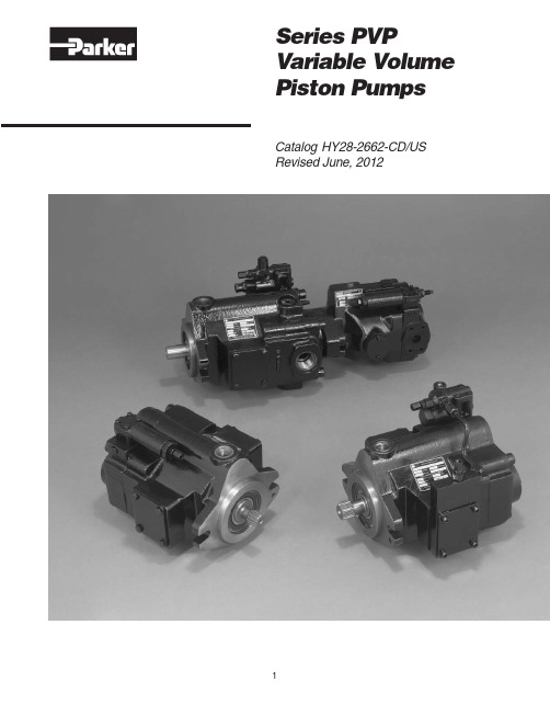
Piston PumpsCatalog HY28-2662-CD/US Revised June, 2012Quick Reference Data ChartDisplacement Pump Delivery† Approx. Noise Levels dB(A)Input Power AtOperating PressurePumpcc/rev @ 21 bar (300 PSI)@ Full Flow 1800 RPM (1200 RPM)1800 RPM, Max.Speed (RPM)bar (PSI)Model(In3/rev)in LPM (GPM)34 bar69 bar138 bar207 bar248 bar Displacement &(Maximum)Continuous 1200 RPM1800 RPM(500 PSI)(1000 PSI)(2000 PSI)(3000 PSI)(3600 PSI)248 bar (3600 PSI)(Maximum)PVP1616(.98)19.7(5.2)29.5(7.8)53 (47)55 (50)59 (54)62 (56)65 (59)13.1 kw (17.5 hp)3000248 (3600) PVP2323(1.4)28.0(7.4)42.0(11.1)61 (57)64 (59)67 (63)69 (65)70 (65)19.7 kw (26.5 hp)3000248 (3600) PVP3333(2.0)39.4(10.4)59.0(15.6)64 (59)66 (59)68 (62)70 (64)71 (65)27.2 kw (36.5 hp)3000248 (3600) PVP4141(2.5)49.2(13.0)73.8(19.5)68 (60)70 (61)73 (65)74 (67)75 (69)33.2 kw (44.5 hp)2800248 (3600) PVP4848(2.9)57.6(15.2)86.4(22.8)69 (60)71 (62)73 (65)75 (68)76 (69)40.3 kw (54.0 hp)2400248 (3600)†Measured in an anechoic chamber to DIN 45635, measuring error + 2 dB(A).Fluid used: petroleum oil to ISO VG 46; temperature = 50°C (122°F).Since many variables such as mounting, tank style, plant layout, etc., effect noise levels, it cannot be assumed thatthe above readings will be equal to those in the field. The above values are for guidance in selecting the proper pump.Features•High Strength Cast-Iron Housing •Fast Response Times•Two Piece Housing For Ease of Service •Metric Pilot, Shaft and Ports Available •Replaceable Bronze Clad Port Plate •Thru-Shaft Capability •Low Noise Levels•Replaceable Piston Slipper PlateControls•Pressure Compensation •Load Sensing•Horsepower Limiting•Horsepower and Load Sensing •Remote Pressure Compensation •Adjustable Maximum Volume Stop •Hi/Lo Torque (Power) Limiting (PVP 41/48, 60/76, 100/140 Only)•Low Pressure StandbySERVO COMPENSA TORPUMP CASE BIAS PLA TE BARREL PLA TE BEARING SEALGeneral DescriptionAll control is achieved by the proper positioning of the swash plate. This is achieved by a servo piston acting on one end of the swash plate working against the combined effect of the off-setting forces of the pistons and centering spring on the other end. The control spool acts as a metering valve which varies the pressure behind the servo piston.As shown in Figure 1, the amount of flow produced by the Parker Piston Pump is dependent upon the length of stroke of the pumping pistons. This length of stroke, in turn, is determined by the position of the swash plate. Maximum flow is achieved at an angle of 15-17degrees. The rotating barrel, driven by the prime mover, moves the pistons in a circular path and the piston slippers are supported hydrostatically against the face of the swash plate. When the swash plate is in a vertical position, perpendicular to the centerline of the piston barrel, there is no piston stroke and consequently no fluid displacement. When the swash plate is positioned at an angle, the pistons are forced in and out of the barrel and fluid displacement takes place. The greater the angle of the swash plate, the greater the piston stroke.Control OptionsBARRELPressure Compensated Control (OMIT)The swash plate angle controls the output flow of the pump. Swash plate angle is generated by the hydraulic force of the pumping pistons and the mechanical force of the swash plate bias spring. Control of the pump’s outlet flow is obtained by over-riding the force of the pumping pistons and bias spring with the hydraulic force of the servo piston by means of internal porting. Pressure is connected from the outlet port to the servo piston via a compensator spool.The compensator spool is held against the spring guide by the outlet pressure. When the outlet pressure reaches the setting of the compensator control, the compensator spool moves, allowing outlet pressure oil to be metered into the servo piston. This metered oil provides adequate force to power the servo piston and override swash plate forces. The outlet pressure causes the servo piston to move which reduces the angle of the swash plate and thereby reduces the pump’s output flow. When flow is again demanded by the system, the outlet pressure will momentarily fall allowing the compensator spool to move. This movement closes off the outlet pressure to the servo piston and vents the servo piston to case. The result of this venting allows the swash plate forces to move the swash plate angle to maximum displacement, thus responding to the demand for additional flow. Note that the compensator spring chamber is vented to the pump case via a hole internal to the compensator spool.PORTRemote Pressure Control (M)The pump swash plate actuation is identical to the standard pressure compensator but can be controlled via a remote pressure control.Remote control of the pump output pressure can be achieved by controlling the pressure at port A, Figure 3 on the compensator. Flow is metered through the orifice in the spool from outlet pressure into the spring chamber. The spring chamber pressure is limited by an external relief connected to port A. The controlled pressure at port A is sensed at the differential spring chamber. The compensator spool will move to the right when the pump outlet pressure reaches a force equal to the differential spring setting plus the controlled port pressure setting. When the spool moves to the right, outlet pressure oil is metered to the servo piston and the pump swash plate angle is controlled accordingly. With this option the pump outlet pressure can be controlled and varied from a remote location.This control also incorporates a pressure limiting feature preset at the factory. When the pressure in the differential spring chamber reaches the maximum relief setting, the dart unseats allowing the spring chamber to vent to the pump case and limits the maximum pressure attainable.Control OptionsCatalog HY28-2662-CD/USFlow Control (Load Sensing) (A)Figure 4 shows a PVP pump with flow control. The control is identical to the remote pressure compensation control except for an integral orifice, a solid compensator spool and adjustable differential pressure control. Port A is connected downstream of an orifice (variable or fixed) to sense the actual working pressure required. This pressure plus the differential spring force act on the right side of the compensatorspool and will urge the spool to the left until output pressure acting on the left side of the spool balances the forces. As the load increases, output pressure will increase and maintain a constant differential pressure across the orifice and thus a constant flow.Maximum pressure is limited by the internal dart setting.This setting is adjustable up to the maximum preset at the factory.Variable Volume Piston PumpsSeries PVPControl OptionsPORTCatalog HY28-2662-CD/USPressure & Power Control (H)This control option is a T orque Limiting Control, but for constant speed applications it is generally referred to as a Horsepower Control. This control works in conjunction with the Remote Pressure Compensator,control option “M”. A second pressure control device called a horsepower control block, is assembled to the main pump housing. The HP block is plumbed to one of the ports on the remote compensator via steel tubing.The control dart in the HP block and the maximum pressure compensator dart in the remote compensator are connected in parallel. What makes the control dart in the HP block different from any other external relief valve is the pressure setting is mechanically linked to the pump swashplate angle.The cracking pressure of the HP dart is generally lower than the cracking pressure of the remote compensator differential spring cavity is lowered allowing the compensator spool to meter system pressure in the servo piston. As the servo piston extends, it rotates the swashplate and in turn rotates the HP cam. As the cam rotates it increases the force on the HP dart control spring. As the system pressure is allowed to increase,the pump gradually reduces its stroke (flow). When the system pressure reaches the setting of the maximum pressure dart the normal action of the remote compensator takes over. If the HP control is set low enough, the pump may reach zero stroke before the system pressure ever gets a chance to open the maximum compensator dart. This should be considered when making low power settings on systems requiring high working pressures.Variable Volume Piston Pumps Series PVPControl OptionsCatalog HY28-2662-CD/USPressure, Power & Flow Control (C)Refer to the previous section(s) on Flow Control and Power Control. This is another case where multiple controls can be combined in parallel. Since the Power Control is just a special version of Remote Pressure Control, it can be combined with the Flow Control (Load Sense) option. The main point to remember here is that the pressure drop which is required to begin and maintain compensation comes from an external device (such as a proportional valve). This sensed pressure drop will control flow until one of the limits of the other controls has been exceeded. The pump will always respond to the lowest control setting for any given pressure. In addition to Load Sensing, Power Control,and on-pump Pressure Control, Remote Pressure Control can also be included in this parallel device package. There is a remote port on the compensator body and one on the HP Control body, either of which may be used for remote pressure control. The important concept to remember in load sense circuits is that each pressure control device in and connected to the compensator must be protected from saturation. For this reason, use only the uppermost port on the compensator for connection of the load sense line and insure that an appropriate orifice is installed. All control options using a load sense compensator spool are supplied with this orifice.Variable Volume Piston Pumps Series PVPControl OptionsCatalog HY28-2662-CD/USHi/Lo Power Control (HLM)(Available with PVP41 and PVP48 Only)The graph shown below represents the flow-pressure characteristics of a Hi-Lo control for PVP pumps. There are up to four separate adjustments that must be made with the pump controls to get a particular setting, all of which influence the shape of the curve. To get the proper settings, it is very important that all pertinent information is supplied with each Hi-Lo pump ordered.As you can see from the graph below, there are two peak power points. Our intention is to have the same magnitude of power required for both peaks. Of course many combination of settings are possible but specification of the settings becomes very difficult. To make factory settings, we need to know the required flow (applicable if pump has a maximum volume stop), the shaft speed , the required Power limit , and the compensation pressure . Based on these requirements, we will adjust the low pressure set point and the reduced flow set point of the Hi-Lo control to best match the requested parameters called out on the order.Important note: As with power controls, not all combinations of flow, power, pressure, etc. are possible.pressure or in a de-stroked condition can have a much lower overall efficiency than expected. The other thing to keep in mind is that the pump will require the peak power at only two points. All other operating pressures will require less than maximum power and therefore the pump will deliver less hydraulic power in the appropriate ratio based on the actual pump efficiency at those conditions.System PressureO u t l e t F l o wTypical Hi-Lo ControlFlow/Pressure CharacteristicsVariable Volume Piston Pumps Series PVPControl OptionsPVP SERIESPRESSURE & POWER COMPENSATORCONTROL OPTION "HLM"Performance InformationSeries PVP16 Pressure Compensated,Variable Volume, Piston PumpFeatures•High Strength Cast-Iron Housing for Reliability and Quiet Operation•Optional Inlet/Outlet Locations for Ease of Installation•Replaceable Bronze Port Plate •Replaceable Piston Slipper Plate•Thru-Shaft Capability SAE A Pilots Offered •Low Noise Levels - Promote More Comfortable Operating Environment •Fast Response Times•Metric Pilot Shaft and Ports AvailableControls•Pressure Compensation•Remote Pressure Compensation •Load Sensing•Torque (Power) Limiting•Adjustable Maximum Volume Stop •Low Pressure StandbySchematic Symbol(Basic Pump)Quick Reference Data ChartDisplacementPump Delivery † Approx. Noise Levels dB(A)Input Power At Pump cc/rev @ 21 bar (300 PSI)@ Full Flow 1800 RPM (1200 RPM)1800 RPM, Max.Model (In 3/rev)in LPM (GPM)34 bar 69 bar 138 bar 207 bar 248 bar Displacement &1200 RPM 1800 RPM (500 PSI)(1000 PSI)(2000 PSI)(3000 PSI)(3600 PSI)248 bar (3600 PSI)PVP1616.4 (1.0)19.7 (5.2)29.5 (7.8)53 (47)55 (50)59 (54)62 (56)65 (59)13.1 kw (17.5 hp)†Measured in an anechoic chamber to DIN 45635, measuring error + 2 dB(A).Fluid used: petroleum oil to ISO VG 46; temperature = 50°C (122°F).Since many variables such as mounting, tank style, plant layout, etc., effect noise levels, it cannot be assumed that the above readings will be equal to those in the field. The above values are for guidance in selecting the proper pump.SpecificationsPressure Ratings Outlet Port:248 bar (3600 PSI) Continuous (P1)310 bar (4500 PSI) Peak (P3)Inlet Port:1.72 bar (25 PSI) Maximum.17 bar (5 In. Hg.) Vacuum Minimum @ 1800 RPM (See inlet chart for other speeds)Speed Ratings:600 to 3000 RPMOperating Temperature Range:– 40°C to 71°C(– 40°F to 160°F)Housing Material:Cast-Iron Filtration:Maintain SAE Class 4,Mounting:SAE “A” or Metric 2-Bolt Flange MountInstallation Data:See page 42 of this catalog for specific recommendations pertaining to system cleanliness, fluids, start-up, inlet conditions, shaft alignment, drain line restrictions and other important factors relative to the proper installation and use of these pumps.*Available with CW rotation only.NOTE: The efficiencies and data in the graph are nominal values and good only for pumps running at 1800 RPM and stroked to maximum. To calculate approximate horsepower for the other conditions, use the following formula:Actual GPM is directly proportional to drive speed and maximum volume setting. Flow loss, however, is a function of pressure only.HP = Q x (PSI) + (CHp)1714[ ]WHERE:Q =Actual Output Flow in GPM PSI =Pressure At Pump OutletCHp =Input Horsepower @ Full Compensation @ 1800RPM(from graph read at operating pressure)45678910100908070F l o wE f f i c i e n c y - %P o w e rPVP16 @ 1200 RPM021315.118.922.726.530.334.137.907.63.811.400Bar PSI 691000138200020730002754000Pressure LPM 03.06.08.911.914.904.08.012.016.020.0HP KW 4567891010090807060F l o wE f f i c i e n c y - %P o w e rPVP16 @ 1800 RPM021315.118.922.726.530.334.137.907.63.811.400Bar PSI 691000138200020730002754000PressureLPM 03.06.08.911.914.904.08.012.016.020.0HP KW12.015.0O u t l e t F l o w @ M a x . D i s p l a c e m e n tFlow vs. Speed010002000300050015002500Shaft Speed - RPM6.03.09.045.557.8022.711.434.1GPM LPM PVP16Inlet Characteristics at Full Displacement(Graph only valid at sea level)10001500500200025003000Shaft Speed - RPMV a c u u mI n l e t P r e s s u r e 6.414.282.14PSI bar 005.1710.3415.5120.68barPower ControlFull Flo w TorquePSI 1000200030004000PressureF l o wT o r q u e012.424.837.049.561.9011022033044055074.3660In-LbsN·mFull Flo w TorquePSI 1000200030004000PressureF l o wT o r q u e09.018.027.036.045.008016024032040054.048063.056072.0640In-LbsN·m T i m e (m i l l i s e c )PVP16 @ 1200 RPM00Bar PSI 691000138200020730002754000Pressure 100125150200T i m e (m i l l i s e c )PVP16 @ 1800 RPM50257500Bar PSI 691000138200020730002754000PressurePVP16Compensated Power@ 1800 RPM00Bar PSI 691000138200020730002754000Pressure2.02.53.0P o w e r01.0.51.51.51.92.20.75.371.1HPKW PVP16Approximate Case Drain Flow@ 1800 RPM 00Bar PSI 691000138200020730002754000Pressure .4.5.6F l o w0.2.1.31.51.92.30.8.41.1GPMLPM Response TimesRear Ported Pump Dimensions* Inch equivalents for millimeter dimensions are shown in (**).NOTE:Illustration shows Righthand (CW) rotation pump. Lefthand (CCW)pumps will have inlet and outlet ports reversed with compensator on outlet side.STRAIGHT THREAD O-RING PORT (9/16-18 UNF-2B)(INCLUDED IN “5” OPTION ONL Y)ADJ. MAX. VOLUME STOP (1.6 CC/REV/TURN)“OPTION 2”Front ViewPilot DimensionsPilot A C D Option OMIT N/A 32.00173.23(1.26)(6.82)538.1028.44144.53(1.50)(1.12)(6.44)FLAADJ. MAX.VOLUME STOP(1.6 CC/REV/TURN)“OPTION 2”Rear View Front ViewSide Ported – Options 2 & 4 Dimensions* Inch equivalents for millimeter dimensions are shown in (**).NOTE:Illustration shows Righthand (CW) rotation pump. Lefthand (CCW) pumps will have inlet and outlet ports reversed with compensator on outlet side.Port Size Type and LocationOption A Inlet and Outlet Ports Drain Port 148.843/4" SAE 4-Bolt FlangeSAE-6 Straight Thread 2(5.86)3/8-16 Thread(9/16-18UNC)Std PSI Series (Code 61)4152.40SAE-16 Straight Thread SAE-6 Straight Thread(6.00)(1-5/16-12UN-2B)(9/16-18UNC)Dimensional DataPilot DimensionsShaft A B C D Option Omit 82.55/82.50 6.1053.09ø 3/8"B, C ø (3.250/3.248)(.24)(2.09)K80.00/79.957.2455.63ø 10mmø(3.149/3.147)(.285)(2.19)Side Ported – Options 8 & 9 Dimensions* Inch equivalents for millimeter dimensions are shown in (**).NOTE:Illustration shows Righthand (CW) rotation pump.ADJ. MAX.VOLUME STOP (1.6 CC/REV/TURN)“OPTION 2”Side ViewThru-Shaft Pump Dimensions* Inch equivalents for millimeter dimensions are shown in (**).NOTES:1.Righthand (CW) rotation pump shown above.Counterclockwise (CCW) pump will have inlet and outlet ports reversed with the compensator over the outlet port.2.Splined shaft (option “B”) not recommended withThru-Shaft pumps.3.The maximum torque transmitting capacity for rearmounting of pumps is limited by the allowable torque of the input shaft.4.Options 6A4 and 9A4 Design Series 12 have a gasket.All other options incorporate an o-ring seal and have an o-ring groove.Port Size Type and LocationOption A Inlet and Outlet Ports Drain Port 148.843/4" SAE 4-Bolt FlangeSAE-6 Straight Thread2(5.86)3/8-16 Thread(9/16-18UNC)Std PSI Series (Code 61)4152.40SAE-16 Straight Thread SAE-6 Straight Thread(6.00)(1-5/16-12UN-2B)(9/16-18UNC)148.843/4" SAE 4-Bolt FlangeISO 6149-68(5.86)M10 ThreadM16 x 1.50Std PSI Series (Code 61)148.843/4" SAE 4-Bolt Flange9(5.86)M10 Thread3/8" - BSPPStd PSI Series (Code 61)Dimensions – Thru Shaft OptionsVARIATIONH GFE DC 6A453.19 (2.09)82.58/82.60 (3.251/3.252)N/A 3/8–16UNC–2B 9 T ooth 16/32 Pitch207.26 (8.16)9A453.19 (2.09)82.58/82.60 (3.251/3.252)N/AM10 x 1.509 T ooth 16/32 Pitch207.26 (8.16)Remote Compensator Control Pump Dimensions* Inch equivalents for millimeter dimensions are shown in (**).NOTES:1.Righthand (CW) rotation pump shown below. Lefthand (CCW) pumps will have compensator on opposite side.2.When controlling pump compensator pressure with remote relief valve, remote relief valve must be capable of passing 1.89 LPM (.5 GPM).3.Remote compensator option “M”, “ME” & “A” available on pumps with any port location.PUMPSISO 6149-4“9” OPTION1/4"TEDC L Side View Front ViewDimensional DataDimensional DataPower (Torque) Control Pump Dimensions* Inch equivalents for millimeter dimensions are shown in (**).NOTES:1.Righthand (CW) rotation rear ported pump shown. Counterclockwise (CCW)pumps will have inlet and outlet ports reversed with compensator and powerblock on outlet side.2.Power control shown on rear ported pump. Also available on side ported or thru-shaft option pumps.Side View Front ViewPerformance InformationSeries PVP 23/33 Pressure Compensated, Variable Volume, Piston PumpsFeatures•High Strength Cast-Iron Housing for Reliability and Quiet Operation•Optional Inlet/Outlet Locations for Ease of Installation•Replaceable Bronze Port Plate •Replaceable Piston Slipper Plate•Thru-Shaft Capability SAE A andB Pilots Offered•Low Noise Levels•Fast Response Times•Metric Pilot Shaft and Ports AvailableControls•Pressure Compensation •Remote Pressure Compensation •Load Sensing•Torque (Power) Limiting •Adjustable Maximum Volume Stop •Low Pressure StandbySchematic Symbol(Basic Pump)SpecificationsPressure RatingsOutlet Port:248 bar (3600 PSI) Continuous (P1)310 bar (4500 PSI) Peak (P3)Inlet Port: 1.72 bar (25 PSI) Maximum.17 bar (5 In. Hg.) Vacuum Minimum@ 1800 RPM (See inlet chart forother speeds)Speed Ratings:600 to 3000 RPMOperating T emperature Range:–40°C to 71°C(–40°F to 160°F) Housing Material: Cast-IronFiltration:Maintain SAE Class 4,ISO 16/13,ISO 18/15 MaximumMounting:SAE “B” or Metric 2-BoltFlange MountInstallation Data:See page 42 of this catalog for specific recommendations pertaining to system cleanliness, fluids, start-up, inlet conditions, shaft alignment, drain line restrictions and other important factors relative to the proper installation and use ofthese pumps. Quick Reference Data ChartDisplacement Pump Delivery† Approx. Noise Levels dB(A)Input Power AtPumpcc/rev @ 21 bar (300 PSI)@ Full Flow 1800 RPM (1200 RPM)1800 RPM, Max.Model(In3/rev)in LPM (GPM)34 bar69 bar138 bar207 bar248 bar Displacement & 1200 RPM1800 RPM(500 PSI)(1000 PSI)(2000 PSI)(3000 PSI)(3600 PSI)248 bar (3600 PSI)PVP2323.0 (1.4)28.0 (7.4)42.0 (11.1)61 (57)64 (59)67 (63)69 (65)70 (65)19.7 kw (26.5 hp) PVP3333.0 (2.0)39.4 (10.4)59.0 (15.6)64 (59)66 (59)68 (62)70 (64)71 (65)27.2 kw (36.5 hp)†Measured in an anechoic chamber to DIN 45635, measuring error + 2 dB(A).Fluid used: petroleum oil to ISO VG 46; temperature = 50°C (122°F).Since many variables such as mounting, tank style, plant layout, etc., effect noise levels, it cannot be assumed thatthe above readings will be equal to those in the field. The above values are for guidance in selecting the proper pump.81012141618201009080706050F l o wE f f i c i e n c y - %P o w e rPVP23 @ 1800 RPM042630.337.945.453.060.668.275.7015.17.622.700Bar PSI 691000138200020730002754000PressureLPM 03.06.08.911.914.904.08.012.016.020.017.920.923.924.028.032.0HP KW HP = Q x (PSI) + (CHp)[ ]NOTE: The efficiencies and data in the graph are good only for pumps running at 1800 RPM and stroked to maximum. To calculate approximate horsepower for the other conditions,use the following formula:Actual GPM is directly proportional to drive speed and maximum volume setting. Flow loss, however, is a function of pressure only.WHERE:Q =Actual Output Flow in GPM PSI =Pressure At Pump OutletCHp =Input Horsepower @ Full Compensation @ 1800RPM (from graph read at operating pressure)81012141618201009080706050F l o wE f f i c i e n c y - %P o w e rPVP33 @ 1800 RPM042630.337.945.453.060.668.275.7015.17.622.700Bar PSI 691000138200020730002754000PressureLPM 06.011.917.923.929.808.016.024.032.040.0HP KWFlow vs. Speed10002000300050015002500Shaft Speed - RPM16.028.0Ou t l e t F l o w @ M a x . D i s p l a c e m e n t08.04.012.060.6106.0030.315.245.524.020.090.875.7GPM LPM PVP 23/33Inlet Characteristics at Full Displacement(Graph only valid at sea level)10001500500200025003000Shaft Speed - RPMV a c u u mI n l e t P r e s s u r e 6.414.282.14PSI bar 005.1710.3415.5120.68barPVP23 @ 1800 RPM00Bar PSI 691000138200020730002754000Pressure81012F l o wT o r q u e42630.337.945.4015.17.622.7019.739.459.178.898.40175350525700875118.11050GPM LPM In-Lbs N·m Power ControlPVP33 @ 1800 RPM00Bar PSI 691000138200020730002754000Pressure81016F l o wT o r q u e42630.337.960.61453.01245.415.17.622.7019.739.459.178.898.40175350525700875157.51400137.81225118.11050GPM LPM In-Lbs N·mResponse Times80100120T i m e (m i l l i s e c )PVP 23/33 @ 1200 RPM40206000Bar PSI 691000138200020730002754000Pressure 80100120T i m e (m i l l i s e c )PVP 23/33 @ 1800 RPM40206000Bar PSI 691000138200020730002754000PressurePVP 23/33Approximate Case Drain Flow@ 1800 RPM00Bar PSI 691000138200020730002754000.4.5.6F l o w.2.1.31.51.92.3.7.82.73.00.8.41.1.93.4GPMLPM PVP 23/33Compensated Power@ 1800 RPM00Bar PSI 6910001382000207300027540002.02.53.0P o w e r01.0.51.51.51.92.20.75.371.13.54.02.63.0HP KWRear Ported Pump Dimensions* Inch equivalents for millimeter dimensions are shown in (**).NOTES:1.Righthand (CW) rotation pump shown. Lefthand (CCW) pumps have inlet and outlet ports reversed.2.Pump shown with standard pressure compensator (control option “omit”)..)Side Ported – Options 2 & 3 Dimensions* Inch equivalents for millimeter dimensions are shown in (**).NOTES:1.Righthand (CW) rotation pump shown. Lefthand (CCW) pumps have inletand outlet ports reversed.2.Pump shown with standard pressure compensator (control option “omit”).Port LocationOption A Inlet and Outlet Port148.841-1/4" SAE 4-Bolt Flange 2(3.10)7/16-14 Threads StandardPressure Series (Code 61) 3152.40SAE-20 Straight Thread(3.22)(1-5/8-12UN-2B)Side Ported – Options 8 & 9 Dimensions* Inch equivalents for millimeter dimensions are shown in (**).NOTES:1.Righthand (CW) rotation pump shown.2.Pump shown with standard pressure compensator (control option “omit”).Pilot DimensionsShaft A B C D Option Omit 101.60/101.559.4072.90ø 12.70B, C, D (4.000/3.998)(.37)(2.87)(.50)K100.00/99.959.1469.85ø 12mm(3.937/3.935)(.36)(2.75)Top View Side View Rear ViewThru-Shaft Pump Dimensions* Inch equivalents for millimeter dimensions are shown in (**).NOTES:1.Righthand (CW) rotation side ported pump shown.Lefthand (CCW) pump will have inlet and outletports reversed.2.Install coupler on shaft of rear pump to dimensionshown then lock down coupler using set screws.3.Options, 6A2, 6A4, 9A4 and 9A5 Design Series 20have a gasket seal, all other thru-shaft optionsincorporate an o-ring seal and have ano-ring groove.4.Maximum torque transmitting capacity 209 N•m(1850 in-lbs).Thru-Shaft OptionsGFEDCBAno i t a i r aV6A4238.51 (9.39)82.58/82.60 (3.251/3.252)53.19 (2.09)3/8-16UNC-2B9 Tooth 16/32 Pitch31.75 (1.25)N/A 6A5238.51 (9.39)82.58/82.60 (3.251/3.252)53.19 (2.09)3/8-16UNC-2B11 Tooth 16/32 Pitch31.75 (1.25)N/A 6B3252.48 (9.94)101.63/101.65 (4.001/4.002)73.03 (2.88)1/2-13UNC-2B13 Tooth 16/32 Pitch41.15 (1.62)N/A 6B4252.48 (9.94)101.63/101.65 (4.001/4.002)73.03 (2.88)1/2-13UNC-2B15 Tooth 16/32 Pitch45.97 (1.81)N/A 9A4238.51 (9.39)82.58/82.60 (3.251/3.252)53.19 (2.09)M10 x 1.509 Tooth 16/32 Pitch31.75 (1.25)N/A 9A5238.51 (9.39)82.58/82.60 (3.251/3.252)53.19 (2.09)M10 x 1.5011 Tooth 16/32 Pitch31.75 (1.25)N/A 9B3252.48 (9.94)101.63/101.65 (4.001/4.00)73.03 (2.88)M12 x 1.7513 Tooth 16/32 Pitch41.15 (1.62)N/A 9B4252.48 (9.94)101.63/101.65 (4.001/4.00)73.03 (2.88)M12 x 1.7515 Tooth 16/32 Pitch45.97 (1.81)N/A。
派克Parker流体连接件中国区产品手册 上

43 系列 ..................................................................................................................................................................A-11
A 高压软管................................................................................................................................................................ .A-9
不断创新
我们的使命是:持续改进,不断创新,朝着更 小、更轻、更节能、更可靠的目标前进,与客 户成为合作伙伴,共同进步。
2
关于派克中国
派克中国总部,位于上海市浦东新区金桥开发区
派克汉尼汾在中国的发展 开始于20世纪80年代,是 改革开放后最早在中国建 立合资公司的美国工业公 司之一。如今,公司产品 已经覆盖了包括能源、轨 道交通、流体处理、行走 液压、海洋开发、工厂自 动化和冶金等超过50个市 场领域。公司总部位于上 海,在成都、北京、广州 等地设有销售办事处。
B
71 系列 ..................................................................................................................................................................A-24
派克Parker伺服电机SMHSMB选型手册
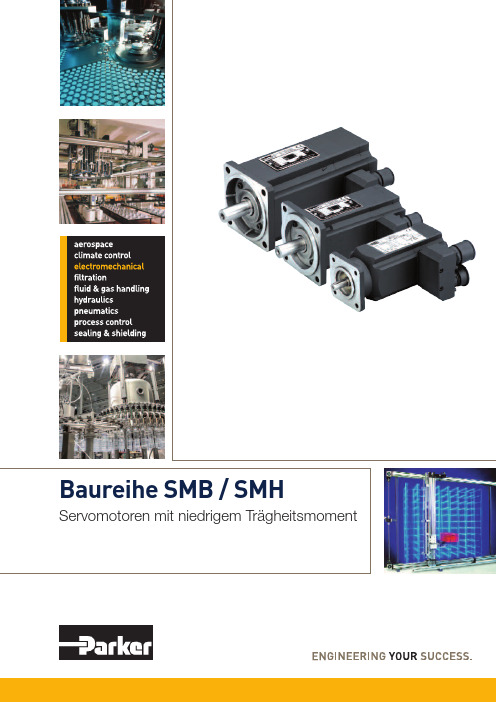
Lokale Fertigung und Support in Europa Ein Netzwerk engagierter Verkaufsteams und autorisierter Fachhändler bietet Beratung und garantiert lokalen technischen Support. Die Kontaktdaten der Verkaufsbüros finden Sie auf der Rückseite dieses Dokuments oder Sie besuchen unsere Website:
2
1
பைடு நூலகம்
Servomotoren mit niedrigem Trägheitsmoment - SMB / SMH Übersicht��������������������������������������������������������������������������� 5 Technische Daten��������������������������������������������������������������� 6
Technische Daten��������������������������������������������������������������������������������������������� 6 Geschwindigkeits-/Momentendiagramme������������������������������������������������������ 8 Abmessungen von Standardmotoren mit Resolver Feedback���������������������� 11
派克换向阀的工作原理以及优点 换向阀工作原理
派克换向阀的工作原理以及优点换向阀工作原理在有些派克PARKER液压系统中,有时需要流量不大的高压油,这时可考虑用增压回路得到高压,而不用单设高压泵。
液压执行元件在工作循环中,某段时间不需要供油,而又不便停泵的情况下,需考虑选择卸荷回路。
在系统的某个局部,派克PARKER液压工作压力需低于主油源压力时,要考虑接受减压回路来获得所需的工作压力。
1.派克PARKER液压泵订立次序动作过程主机各执行机构的次序动作,派克PARKER液压依据设备类型不同,有的按固定程序运行,有的则是随机的或人为的。
工程机械的操纵机构多为手动,一般用手动的多路换向阀掌控。
加工机械的各执行机构的次序动作多接受行程掌控,当工作部件移动到确定位置时,通过电气行程开关发出电信号给电磁铁推动电磁阀或直接压下行程阀来掌控接续的动作。
行程开关安装比较便利,而用派克PARKER液压行程阀需连接相应的油路,因此只适用于管路联接比较便利的场合。
另外还有时间掌控、压力掌控等。
例如派克PARKER液压液压泵无载启动,经过一段时间,当泵正常运转后,延时继电器发出电信号使卸荷阀关闭,建立起正常的工作压力。
压力掌控多用在带有液压夹具的机床、挤压机压力机等场合。
当某一执行元件完成预定动作时,回路中的压力达到确定的数值,通过压力继电器发出电信号或打开次序阀使压力油通过,来启动下一个动作。
2.派克PARKER液压泵选择液压动力源液压系统的工作介质完全由液压源来供应,派克PARKER液压源的核心是液压泵。
节流调速系统一般用定量泵供油,在无其他辅佑襄助油源的情况下,液压泵的供油量要大于系统的需油量,多余的油经溢流阀流回油箱,溢流阀同时起到掌控并稳定油源压力的作用。
容积调速系统多数是用变量泵供油,用安全阀限定系统的高压力。
为节省能源提率,派克PARKER液压泵的供油量要尽量与系统所需流量相匹配。
对在工作循环各阶段中系统所需油量相差较大的情况,一般接受多泵供油或变量泵供油。
- 1、下载文档前请自行甄别文档内容的完整性,平台不提供额外的编辑、内容补充、找答案等附加服务。
- 2、"仅部分预览"的文档,不可在线预览部分如存在完整性等问题,可反馈申请退款(可完整预览的文档不适用该条件!)。
- 3、如文档侵犯您的权益,请联系客服反馈,我们会尽快为您处理(人工客服工作时间:9:00-18:30)。
专售进口派克马达F11需要请拨打:《150-5979(8003)》(吴工)0595/<2876—7801> (扣扣):77-188-32-47公司的技术核心人员是许多国际和德国标准的委员会的委员,直接参与工业、建筑、医疗、交通等领域有关电气安全和测量标准的制定,这使公司具备了潜在的发展优势,并奠定了公司在低压系统漏电保护技术上的全球领先地位。
产品详细信息,欢迎来电查询!要是您想要的,我都能帮您找到,价格从优!
Parker液压产品授权北京分销商。
Parker Hannifin派克汉尼汾是全球一流的运动控制公司, 致力于提供用户一流的服务. 派克是唯一能够给用户提供全方位液压,气动,和机电一体化运动控制方案的制造商之一。
派克公司气动部门,兼并了众多世界著名的气动工厂,使派克气动产品日益壮大,在气动行业中名列前茅,派克旗下的著名品牌:Atlas Automation、SchraderBellows、Telepneumatic、wilkerson、Miller、sempress、Watis、maxam、climax、invensys、ParkerKuroda、Parker TAIYO。
英格索兰气动马达150BMPE88R54-12C
德国KRACHT克拉克泵KF40RF1-232-D15
SPM大泵连杆瓦2P112860
DERRCIK德瑞克振动筛手压油泵G0001992 COREMO科锐盟制动器E4-A1934 DERRICK交流电动机EX30-15-415-007-J DERRICK德瑞克电机EX-2.5HP415/50HZ/3PH 福伊特齿轮泵IPV6-80-101
PLT迷你抛绳器M-75
MOOG穆格伺服阀743F003A
Riovibro测振仪Vm-63a
艾默生充电模块HD22010-2
诺冠减压阀20AG-X6G/PH100
FMC泵M1832HD
英格索兰启动马达KK6M现货
MOOG伺服阀D631-102C现货
GEMU双作用角座阀514-50D-137531
GEMU単作用角座阀514-15D-137514 National油封456967v
意大利INTERPUMP高压柱塞泵W2141现货ARCOTRONICS电容C20ALGR5680AA0K PRATISSOLI泵KLS36现货
INTERPUMP高压柱塞泵W2141
威格士减压阀XG2V-6BW-10
罗斯蒙特差压变送器3051CD2A22A1AB4M5
罗斯蒙特压力变送器3051GP3A2B21AB4M5 Calpeda科沛达水泵TP100E
UFM流量开关MN-DSF320LM-16FTCSI50RF现货CAT猫牌柱塞泵5CP3120CSS
CAT猫牌柱塞泵5CP3120CSSG1
丹佛斯油泵VBHM-D-4-10现货
FLOJET泵04300-242现货
NUFLO流量计9A-100009536
ASCO电磁阀EF8320G202/24DC
霍纳编码器HIS1017252现货
TROMBETTA启动器NO684-1261-212
马勒过滤器PI3405-012现货
NOP油泵TOP-206HB
马祖奇齿轮泵ALP4A-D-130-S1
英格索兰气动马达ST400ICAR72
贺德克压力传感器EDS1791P-600-009
Parker PUMP and Motor Division
Part No.3785609
TYPE SER NO.F12-090-MF-IV-K-000-000-0
Parker PUMP and Motor Division
Part No.3785518
TYPE SER NO.F12-090-MF-IV-D-000-000-0
Parker PUMP and Motor Division
Part No.3780784
TYPE SER NO.F12-080-MS-SV-T-000-000-0
Parker PUMP and Motor Division
Part No.3780767
TYPE SER NO.F12-080-MF-IV-K-000-000-0
Parker PUMP and Motor Division
Part No.3799989
TYPE SER NO.F12-060-MF-IV-K-000-000-0
Parker PUMP and Motor Division
Part No.3799988
TYPE SER NO.F12-060-MF-IV-D-000-000-0
Parker PUMP and Motor Division
Part No.3799999
TYPE SER NO.F11 060 MS SV T 000
Parker PUMP and Motor Division
Part No.3703665
TYPE SER NO.F11 005 MB CN K 000
F12-060-MS-SV-T-000液压加气马达CNG加气站
泉州双环专业供应派克Parker马达,型号齐全。
F11-005-MB-CE-K-000破碎机马达直销,不经过二手转卖,低价让利顾客力求双赢客户有赚我们才有赚!我们旨在为客户提供全球配件解决方案
派克高速马达F11/F12系列
该系列马达均采用球面柱塞设计,允许传动轴承受相当大的外部轴向和径向负载,最高工作压力480 bar;
配有精心设计的配流盘,降低了噪声,能在极高的轴转速下工作,最高转速可以到710rpm;
具有高度设计的泵阀板,增加了其自吸速度和低噪音,整个工作过程中(转速和压力由低到高的)工作噪声均很低。
层叠式的活塞环具有减少内泄漏量及耐热至冲击的特点。
CAT猫牌泵5CP3120
CAT猫牌泵5CP3120CSS
CAT猫牌泵5CP3120G1现货
博士发电机0120689569现货
TYCO泰科探头811H现货
DUNKERMOTOREN德恩科永磁直流电机G42*25 德国库伯勒KUBLER编码器8.5020.3351.0512现货JASC截止阀101284-100现货
BALDOR编码器924-01070-314现货
博世BOSCH马达0001230014现货
派克油泵DP14R-310C
CAT猫牌蓄能器6030
CAT猫牌调节阀7531
英格索兰马达150BMP8R/105-5081
英格索兰气动马达150BMGE21RH-6现货
三菱压缩机LH48V AAC
力士乐柱塞泵A10VSO140 DFR/31R-VPB12NOO
德国LEMAG电子示功器PREMT-LS
德国威乐泵MHI-206EM
小巨人泵RIM-U 545600现货
KOHLER科勒起动机2509811
VICKERS威格士叶片泵35V-35A-1C-22R
CAT猫牌泵1051现货
NUFLO流量计9A-100009371
马丁戴克指重表AWE9H-17现货
Parker派克泵P2105R00C1C18TA20N43S1B4P
派克汉尼汾公司(纽约股票交易所股票代码“PH”)是一家总部位于美国的世界一流的工业企业。
自1918年Arthur L.Parker先生创立公司至今,派克汉尼汾公
司已发展为全球运动和控制领域最大、产品种类最完备的公司。
[2]
派克汉尼汾公司是全球一流的运动控制制造公司,致力于提供一流的产品及用户服务。
作为纽约证券交易所500强公司之一(纽约证交所交易代码:PH),元件和系统超过1400余条生产线,在运动控制方面分布于1000多个工业和航空领域。
派克汉尼汾公司是唯一一家为客户提供液压、气动和机电一体化运动控制方案的制造商。
