HVM过滤器用户手册
常用多介质过滤器用户使用手册(全)

注:长时间停运后开车,应从反洗(一)工序开始。
七、注意事项:
1. 如过滤器为单台,反洗时关闭加药系统。 2. 过滤器反洗时,反洗阀须慢慢开启,以免水流太大带走滤
料;气擦洗步骤同样。 3. 严禁在设备本体或阀组的钢衬胶管道表面进行电焊、气割作
各阀门开度的设 定
检查流量、液面等以验 证各个阀门的设定符合 规定值
根据运行说明要求检查 后, 为确保设定值将阀门 开度锁定
检查各处压力
各个压力表点压力值正 常
压力异常,采取处理措施
3. 日常运行检查:
进入正常生产后, 操作人员每小时要巡回检查设备现场,并记录。
检查周期 检查项目 检查方法或检查点
备注
—— 3min
排水
—— ——
反洗
气擦 洗
水反洗
静置
正洗二 备用
——
—— —— —— ——
—— ——
—— —— 3min 10min 3min 20min
九. 维护保养
1. 试车准备阶段检查:
设备在安装、配管、仪表工程全部完工,且设备本体及配管的清洗
工作结束,应按照下列检查项目进行检查、维护。
检查项目
判断标准
保养维修
内部是否干净
无任何异物
彻底清扫干净
阀门的开闭检 各个阀门按照操作程
转动不灵活可加入润滑 油;回转不正常,检查原
查
序,正常开闭正常
因予以纠正
2. 试车运行调试阶段的检查;
试车运行调试阶段须对下列项目进行检查。
检查项目
判断标准
保养维修
v型滤池操作手册

V型滤池深圳市清泉水业股份有限公司1. 系统总体设计1.1系统结构净水间自控系统采用“集中管理、分散控制”的集散控制策略,分⑴加药站(1台)⑵滤池公共控制主站(1台)⑶滤池就地控制从站(6台)⑷中控上位机(1台)滤池就地控制从站和公共控制主站构成国际标准现场总线PROFIBUS网络,主站采用轮询的方式周期性地同从站交换数据。
公共控制主站和上位机、加药控制系统采用以太网的方式通讯。
1.2.功能概述各个站负责数据采集和必要的控制,中控上位机负责采集现场数据并以动画的形式反映在上位机画面中,操作员或管理者可以通过上位机直观地了解到现场设备的运行状况,且上位机能够就非正常工况显示报警,提示值班人员及时采取措施。
1.3净水间V型滤池1.3.1概述滤池是水厂净水工艺中的重要环节,而滤池过滤能力的再生,是滤池稳定高效运行的关键。
若采用较好的反冲洗技术,使滤池经常处于最优条件下工作,不仅可以节水、节能,还能提高水质,增大滤层的截污能力,延长工作周期,提高产水量。
V型滤池是由法国得利满公司开发的一种快滤池,因进水采用V型槽而得名。
V型滤池采用均粒滤料,通过V型槽布水,采用小阻力的滤头滤板分配反冲洗的气和水,滤池中间设H槽排水槽,采用低强度水反冲洗,反冲时滤料微膨胀,边反冲边排水。
它的主要特点是:(1)采用均质滤料,滤层的纳污能力得到增强与普通级配滤料相比,均质滤料颗粒比较均匀,有效粒径较大,能有效消除冲洗时的水力筛分现象,使滤层孔隙率增大,从而提高滤层的整体含污能力,延长过滤周期,降低洗砂水耗,增加产水量。
(2)丫型滤池过滤能力的再生,采用了先进的气、水反冲洗兼表面扫洗技术。
气、水反冲再加始终存在的横向表面扫洗,冲洗效果好,冲洗水量大大减少。
丫型滤池最大的特点是在冲洗过程中引入了气洗,整个冲洗过程分三步进行:①单气洗:松动整个滤层,水冲洗时不易剥落的污物在气泡急剧上升的高剪力下得以剥落;②气水联合冲洗:气冲使得滤料颗粒间的碰撞磨擦加剧,在水冲洗时,对滤料颗粒表面的剪切作用也得以充分发挥,加强了水冲效能;③水冲:单水冲把脱落的杂质带出滤料层。
过滤器使用说明书
微孔过滤器ZG-10.0使用说明书制作单位:生产基地:公司:公司传真:邮 编:编制日期:目录一、 产品介绍 (3)二、产品特点 (3)三、滤芯的选择 (3)四、设备技术参数 (4)五、使用说明 (4)六、操作注意事项 (6)七、设备的维护与保养 (6)八、售后服务承诺 (7)九、合格证 (7)十、随机附件表 (8)一、产品介绍:本设备可用于食品、乳品、饮料、酒类、中药、化工行业的液体物料的气体的过滤..采用折叠式滤芯;折叠式滤芯是一种先进的固定型深层过滤芯;过滤公称精度范围可以从0.1μm直600.1μm..滤膜不受进料压力波动而影响过滤精度..其特有的低压差;高通量、良好的过滤精度能较低的经济费用成为取代线绕式、棉饼和纸板等非固定型过滤芯的新型滤芯而深受用户欢迎..二、产品特点:①化学相容性广、流通量大、压差低、使用寿命长..②过滤精度范围广、选择度大、可满足各种应用场合..③采用热熔工艺;牢固且无释放物污染产品..三、滤芯的选择:1、滤芯的用途很广泛;滤芯的品种、规格较多;选择型号是很重要的..根据用途可分为过滤液体和气体二种;规格大小可以分为5〃、10〃、20〃、30〃和40〃等..工作压力一般在0.1Mpa—0.4 Mpa..由于滤芯孔径不同;其流量也不尽相同;如0.2um—0.4 um过滤沌水的标准在300—500kg/h;如果要提高每小时的过滤量;则可以用多芯或20〃、30〃、40〃英寸组合;例如要过滤5t/h的无菌水;则可以选用0.2 um;30英寸7芯的过滤器..若过滤杂质多且有粘度;则应添加前置预过滤设备..气体的过滤与液体过滤稍有不同;它的过滤量以每分钟立方气体来计算..10英寸滤芯;孔径φ0.22 um;压力在0.12 Mpa;压差在0.01 Mpa时;流量为4-6m3/min;在发酵工业上广泛应用..2 、合适的滤芯;选用适当的孔径;若要除菌则选用0.2um-0.5um孔径的滤芯、药用针剂、抗菌素、血制品等用聚砜滤芯..如果要去除液体中的微粒;微生物和细菌大一些的离子、杂质;如白酒、黄酒、葡萄酒、口服液、可选用1-5um的孔径即可..过滤高温气体和发酵空气消毒气体要选用聚四氟乙烯滤芯..3 、不锈钢筒式过滤器;它内部装有不同孔径的滤芯..要达到精滤的目的;前期必须用预过滤设备生啤用硅藻土;纸板过滤机..药厂用板框、熔喷、绕线式;再用微孔除菌过滤芯;这样就能达到精滤的目的..4、一般用矿泉水、药用无菌水、电子工业集成电路用水、食品工业用高质量的水..筒式微孔过滤器设计时应成为一个独立的过滤系统;它可以带反冲洗;节省生产成本..5 、除了选择高质量的滤芯;还要选择高质量的过滤器;不锈钢加工是否精细;内外是否光洁;特别是插口处222、226、平口等三种形式是国际通用的;千万不能搞错;否则无法使用;或者由于加工粗糙;插上去起不到密封过滤的效果..注:在使用不锈钢外壳时要注意过滤液体对不锈钢是否有腐蚀作用;不适用的应选用其它材料的过滤器..四、设备技术参数:五、使用说明:1、安装底座:安装前看清进、出口方向..液体应从滤芯外部流向中心;与滤芯插口相通的管道是出口..在滤器管道上有箭头标示流向;切勿接错..2 、安装滤芯:222插口为插入式;226插口为卡入式..如果是多芯应将压板套在翅片上;将螺栓适度拧紧滤芯在高温下会受热伸长;若压板过紧;滤芯无伸长空间会产生扭曲变形影响过滤精度..3 、装好外罩并与底座用卡箍单芯或螺栓多芯连接密封好;注意密封垫要放置平整;检查密封处无渗漏..4 、滤器消毒:新过滤器使用前必须清洗干净..用于除菌的过滤器要杀毒消菌;消毒工作一般应在生产线进行;以免外界污染..现场蒸汽消毒应严格控制蒸汽压力与压差;避免因过高蒸汽压力和压差而损坏滤芯..5 、过滤液体时;应先打开过滤器顶部的排气阀;把筒内的气体排尽;让液体充满筒内;否则会影响流通量..6 、过滤介质流过滤器时会因受到阻力产生压力降即进入与流出时的压力差;为了克服这种阻力;保持足够的流量;必要时要有足够的工作压力..每种滤芯我们都给出了相应的温度、压力限定值;请用户按要求使用..为不使滤芯受到过大流量的冲击;开启阀门时一定要缓慢7 、自选泵配套使用时;请注意流量与压力要匹配..以选旋涡泵、输液泵等自吸泵为宜..8 、停机时应放光滤液;如果时间不长;可不必打开滤器;若时间较长;或滤液不宜长时间存放;则要清洗滤器或滤芯..六、操作主要事项:1 、过滤器使用前必须检查配件和密封圈是否安全;有无损坏;然后按要求把它装好..2、过滤器必须用清洁剂洗干净请不要用酸类清洗洗净后用高温蒸汽杀菌、消毒洗的过滤器进出口要包封好;避免污染..3 、安装时进出口不要接反;一般原则外进内出滤芯..4 、芯是生产厂家在洁净的生产厂房内用塑料袋封装的;未使用切勿撕破塑料包装..使用要求较高的滤芯;应先测气泡点检查滤芯完整性;安装好后要经过高温蒸汽杀菌消毒..5 、入口时;一定要垂直;插入时先用无菌水或经过过滤的滤液湿润一下密封圈;以减少插入时的摩擦阻力..222滤芯插入口后;再用压板扣住尖端翅片;拧紧螺丝不动即可..226接口的滤芯插入后;应选90度卡紧;如果有一点不小心;就会达不到密封;容易漏水而达不到您的使用要求..6、过滤的液体进入时;应打开过滤器上面的放气阀;让液体充满滤器内;否则将影响过滤效果..7、筒体的压力表是显示过滤气内液体的压力;如果是二级过滤;第一道过滤器压力表指数稍小一些是正常现象;随着使用时间的增长;他们的压差会增大;流速减少;这说明滤芯孔隙大多已被堵塞;就要清洗或更换滤芯..8 、在过滤时;使用的压力一般在0.1Mpa左右;能满足生产需要就可以了;随着时间与流量的增加;滤芯微孔被堵塞;压力将会增加;一般不要超过0.3Mpa;最告绝对不能超过0.5Mpa..否则滤器滤芯将会被击穿;发生意外事故;如果确定在0.5Mpa以上的可以与我们联系;我们将根据您的要求为您另外加工..9 、反冲洗滤芯;一定要用无菌水;否则会污染滤芯;反冲洗方法..原出口变进口;把无菌水反方向打进要注意关闭原液过滤管道;打开排污口;操作人员看到滤液明显好转为宜..10、滤芯不用时;应尽量把滤液放光;滤液不宜隔夜存放..停机时间不长时一般不要打开滤器;不要拔掉滤芯;停机时间长;在再次使用前一定要清洗滤芯和滤器也可以用反冲方法进行冲洗..11、我公司生产的滤芯耐温一般在25℃--50℃为宜.长期操作温度应控制在60℃以下;消毒温度121℃以下30分钟;如果操作温度较高;则可以用内衬不锈钢的增强聚四氟乙烯滤芯.12、如果要过滤化学溶剂和高浓度化学品可详见滤芯使用说明书;或者与我公司联系用特殊滤芯来解决..13、若是自选配套使用;则要注意需要的流量、压力及泵的扬程要匹配;一般选用旋涡泵;输液泵等为宜;材料为304或316L不锈钢;端面选用机械密封..七、设备的维护与保养:1、长期停用的过滤器;必须把滤器内外清洗干净;滤芯取下;洗净烘干;用塑料袋封口存放;以免损坏..清洗剂请勿用盐酸类腐蚀性物质;温度不宜过高防止聚丙烯发生变形..存放时避免污染与撞击..2、下来的滤芯若应浸泡在酸碱洗液里;浸泡时间不得超过24小时;酸碱液温度一般在20℃--25℃..建议酸或碱与水的比例是20%为好..最后用无离子水反复冲洗..蛋白质含量较商的滤液;滤芯最好用酶溶液浸泡清洗效果好;重新再使用时;使用前一定要先清洗干净;然后再用蒸气消毒..3、滤芯消毒时要注意掌握时间和温度;聚丙烯在高温消毒柜里以121℃为宜;用蒸汽消毒在0.1 Mpa蒸汽汽压力下;以130℃/20分钟为宜;聚砜和聚四氟乙烯用蒸汽消毒时可以达到142℃;压力0.28Mpa;时间在30分钟左右为宜;如果温度过高;时间过长;压力过大;则会损坏滤芯..八、售后服务承诺:1)及时向需方提供按合同规定的全部技术资料各图纸;有义务在必要时邀请需方参与供方的技术设计审查..2)按需方要求的时间到现场进行技术服务;指导需方按供方的技术资料各图纸要求进行安装、分部与整套试运及试生产..3)对于需方选购的与合同设备有关的配套设备;供方应主动提供满足设备接口要求的技术条件各资料..4)严格执行供需双方就有关问题如开会议的纪要或签订的协议..5)根据需方的要求为需方举办有关设备安装、调试、使用、维护技术的业务培训;保证需方运行、维修人员熟练掌握运行各维修技能..6)加强售前、售中、售后服务;把“24小时服务”;“超前服务”;“全过程服务”;“终身服务”贯彻在产品制造;安装、调试、大修的全过程..7)接到需方反映的质量问题信息后;在24小时之内做出答复或派出服务人员;尽快到达现场;做到用户不满意;服务不停止..8)随时满足需方对备品备件的要求..9)无论在何种情况下;供方决不以任何理由刁难需方..九、合格证十、随机附件表。
一次盐水作业指导书(最终版04-10-14)2

作 业 指 导 书(第一版)文件名称:电解车间一次盐水作业指导书编 写: 时 间:校 核:卢万明 时 间:审 核:刘建军 时 间:审 定:石广伟 时 间:批 准:是建新 时 间:目 录一任务1二、岗位职责1三、工艺流程简述1四、岗位开车操作2五、正常运行操作5六、正常停车操作5七、紧急事故停车操作8八、生产调节、不正常现象处理及事故处理8九、工艺指标一览表9十、安全注意事项10十一、一次盐水工序设备一览表11十二、附录一1HVM膜过滤用户手册15一、任务本工序的任务为二次盐水工序提供合格的一次盐水。
本工序由化盐与精制岗位,过滤岗位,压滤岗位组成。
二、岗位职责2.1职责范围2.1.1全面完成车间,工段,班组下达的任务和要求2.1.2 操作人员必须熟习本岗位的设备、管道、阀门、仪器及仪表的性质及用途,熟习本岗位的工艺流程,控制指标。
做到一次精盐水合格率为100%.2.1.3督足上盐岗位,根据生产需求调配盐种,并保障化盐桶有效盐层高度,监护上盐岗位按时上盐,用配水管调整化盐桶出口浓度,化盐温度每小时做一次原始记录2.1.4将淡盐水,工业水在配水缸中用蒸汽加热,空气搅拌后,经盐水加热器自调温度供化盐使用2.1.5严格控制每个系统流量,要求控制均匀,波动小并及时调整反应液面保持在1/2—2/3范围内。
2.1.6每小时对粗盐水过碱量测定分析一次及时调整精制剂的加入量,保证精盐水的PH值在10—11之间。
2.1.7负责用泵给氯化钡高位槽,纯碱高位槽、三氯化铁高位槽供液同时保证电液位不得小于低位。
2.1.8在向碱液高位槽进料时,不得离开,以防冒碱。
2.1.9加强设备的维护保养工作(设备,管道,阀门,仪表,电器)和安全生产,防止各类事故,杜绝跑,冒,滴,漏。
2.1.10搞好区域内环境卫生。
2.1.11对本岗位的事故处理,要做到准确判断,果断处理。
2.1.12有权制止违章作业,制止非岗位人员乱动阀门、仪表电器等。
三、工艺流程简述3、1 化盐与精制岗位电解来的淡盐水流入1#折流槽(D0101)与氯化钡配制槽(F0101)中配成20%的BaCl2溶液反应,流入澄清桶(F0102),清液由澄清桶的上部溢流入配水槽(F0103ab),硫酸钡从澄清桶底部排出。
HVM过滤器用户手册

H V M膜过滤器用户手册凯膜过滤技术(上海)有限公司目录一、操作说明二、设备维修保养须知三、运行状态表及电器接线图四、主要配件规格表五、产品合格证六、安装说明一、操作说明书1.主要技术规格型号: HVM-120- CS/R-TM - B(1) 设备参数过滤面积 120.00 m2过滤压力 < 0.15 MPa最高工作温度< 60 ℃设备容积12.7m3设备自重5500Kg直径×高度 2.0×5.9m(2)使用动力形式及消耗2.过滤系统工作原理(1) 结构过滤器由罐体,反冲罐,管道,自动控制阀,过滤元件,自动控制系统,气动控制系统等组成。
(见设备图)(2) 工艺流程图(3) 工作原理过滤液通过 1#阀进入过滤器,并经过HVM膜过滤膜进行过滤。
清液经过过滤膜进入上腔(清液腔),并通过液位罐清液管至精盐水贮槽;过滤液中的固体物质(滤渣)被过滤膜截流在过滤膜表面。
当过滤一段时间后,过滤膜上的滤渣达到一定厚度后,过滤器自动进入反冲清膜状态,1#、4#、7#阀按各自的功能自动切换,使滤渣脱离过滤膜表面并沉降到过滤器的锥形底部,过滤器自动进入下一个过滤、反冲、沉降周期;当过滤器锥形底部的滤渣达到一定量时,过滤器自动打开 6#阀排出滤渣,然后重新进入下一运行循环周期。
(见系统工作原理图)3.控制器操作说明(1) 启动:●检查电源接地是否良好,电源电压 220V 50Hz。
●检查电源无误后,开启电源开关(在控制箱背面)。
●显示屏显示:TIME (SEC) 位置开始计秒显示,SET C.C (CYCLE COUNTER) 位置显示为设定值,其他显示 0。
(2) 面板示意图:(3) 显示窗功能●TIME:状态运行时间。
●SET TIME:状态设定时间。
● C.C(CYCLE COUNTER):运行过滤循环次数。
●SET C.C(CYCLE COUNTER):设定过滤循环次数。
●STEP:运行状态。
高效过滤器操作使用维护说明书
高效过滤器操作使用维护说明书高效过滤器操作使用维护说明书1. 基本参数1.1 运行滤速:8m/h1.2 进水浊度: <5mg/L1.3 出水浊度: <1mg/L1.4 反洗强度:8L/㎡·S1.5 气洗强度:12L/㎡·S1.6 反洗时间:4-6min1.7 工作温度:5-40℃1.8 工作压力:≤0.6MPa1.9 滤料高度:1200mm1.10 填料成分:石英砂、无烟煤、鹅卵石2. 结构及工作原理原水在管道内加入絮凝剂,絮凝剂在水中发生离子水解和聚合过程,水中胶体粒子对水解及聚集的各种产物进行强烈的吸附,使粒子表面电荷和扩散厚度同时降低,因而粒子间相互排斥能降低,相互接近而凝聚,水解产生的聚合物被两个以上的胶体吸附后,在粒子间产生架桥联接,逐步形成较大的絮凝体,经过高效过滤器时,为滤料载留。
高效过滤器是以成层状的石英砂、无烟煤作为床层.床的顶层由最轻和最粗品级的材料组成,而最重和最细品级的材料放在床的低部。
其原理为按深度过滤--水中较大的颗粒在顶层被去除,较小的颗粒在过滤器介质的较深处被去除。
从而使水质达到粗过滤后的标准。
多介质过滤器可去除水中水中的悬浮物、有机物、胶质颗粒、微生物、氯、嗅味及部分重金属离子等,并降低水的SDI值,满足深层净化的水质要求。
该设备具有造价低廉,运行费用低,操作简单;滤料有石英砂、无烟煤、鹅卵石,经过反洗,可多次使用,滤料使用寿命长等特点。
高效过滤器的吸附是一种物理吸附,按滤料的填装方式大体可分为松散区(粗砂)、紧密区(细砂),悬浮物质在松散区主工通过流动接触产生接触凝聚作用,所以该区域截留较大颗粒的悬浮物质,在紧密区主要是惯性碰撞及悬浮颗粒间的吸附作用,所以该区域是截留较小颗粒的悬浮物质。
当高效过滤器因截留过量的机械杂质而影响其正常工作,则可用反冲洗的方法来进行清洗。
利用逆向进水,同时通入压缩空气,进行气水混合擦洗,使过高效过滤器内滤层松动,可使粘附于石英砂表面的截留物剥离并被反冲水流带走,有利于排除滤层中的沉渣、悬浮物等,并防止滤料板结,使其充分恢复截污能力,从而达到清洗的目的。
Millex-GV HV 13mm 筛膜过滤器说明书
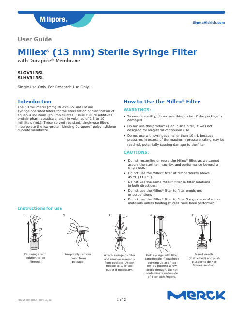
IntroductionThe 13 millimeter (mm) Millex®-GV and HV aresyringe-operated filters for the sterilization or clarification ofaqueous solutions (column eluates, tissue culture additives,protein pharmaceuticals, etc.) in volumes of 0.5 to 10milliliters (mL). These solvent resistant, single-use filtersincorporate the low-protein binding Durapore® polyvinylidenefluoride membrane.1Fill syringe with solution to befiltered.2Aseptically removecover frompackage.3Attach syringe to filterand remove assemblyfrom package. Attachneedle to Luer-slipoutlet if necessary.4(and needle if attached)pointing up and “topoff” by pushing a fewdrops through. Do notcontaminate undersideof filter with fingers.5Insert needle(if attached) and pushplunger to deliverfiltered solution.User GuideMillex® (13 mm) Sterile Syringe Filterwith Durapore® MembraneSLGVR13SLSLHVR13SLSingle Use Only. For Research Use Only.How to Use the Millex® FilterWARNINGS:• To ensure sterility, do not use this product if the package isdamaged.• Do not use this product as an in-line filter; it was notdesigned for long-term continuous use.• Do not use with syringes smaller than 10 mL becausepressures in excess of the maximum pressure rating may bereached, potentially causing damage to the filter.CAUTIONS:• Do not resterilize or reuse the Millex® filter, as we cannotassure the sterility, integrity, and performance beyond asingle use.• Do not use the Millex® filter at temperatures above45 °C (113 °F).• Do not use the same Millex® filter to filter solutionsin both directions.• Do not use the Millex® filter to filter emulsionsor suspensions.• Do not use the Millex® filter to filter 5 mg or less of activematerials unless binding studies have been performed. Instructions for useThe life science business of Merck operates as MilliporeSigma in the U.S. and Canada.Merck, Millipore, Millex, Durapore, and Sigma-Aldrich are trademarksof Merck KGaA, Darmstadt, Germany or its affiliates. Detailed information on trademarks is available via publicly accessible resources.© 2020 Merck KGaA, Darmstadt, Germany and/or its affiliates. All Rights Reserved.SpecificationsMaterials MembraneLow binding hydrophilic polyvinylidene fluoride (PVDF)Pore size:M illex ®-GV filter: 0.22 μmMillex ®-HV filter: 0.45 µm Housing High density polyethylene (HDPE)Dimensions Inlet to outlet 21.1 mm (0.83 in.)Diameter 14.7 mm (0.58 in.)Filtration area0.65 cm 2 (0.10 in 2)Temperature limit 45 °C (113 °F) maximum Housing Pressure at 21 °C5.2 bar (75 psi) inlet and differential Filtration volume 0.5–10 mLHold-up volume ≤ 50 μL after air purge Sterilization method Ethylene oxide gas ConnectionsFemale Luer-Lok™ inlet; male Luer-slip outlet Millex ®-GV Filter Flow Rate ≥ 7 mL/min at 2.1 bar , 21 °C (30 psi, 70 °F)Millex ®-HV Filter Flow Rate≥ 12 mL/min 0.7 bar , 21 °C (10 psi, 70 °F)Chemical CompatibilityMillex ® filters with Durapore ® membrane are compatible with most aqueous solutions. Based on information from technical publications, materials suppliers, and laboratory tests, we believe that the agents listed in the following table are safe to usewith Millex ® filters. However , because of the effects of variability in temperature, concentrations, duration of exposure, and other factors outside of our control, We do not provide or imply a warranty with respect to this information. Agents that are not listed should be tested with the Millex ® filters prior to use.ChemicalsAcetic acid (5%)Acetic acid, glacial AcetonitrileAmmonium hydroxide (6 N)Amyl alcoholBenzyl alcohol (1%)Boric acidBrine (sea water)Butyl alcohol CyclohexanoneDevelopers (photo)Ethyl alcoholEthylene glycol FormaldehydeFreon ® solvent, TF or PCA GasolineGlycerine (glycerol)Helium HexaneHydrochloric acid Hydrofluoric acid Hydrogen (gas)Hypo (photo)Isobutyl alcoholIsopropyl alcohol KeroseneMethyl alcohol Mineral spirits PentanePetroleum based oils Phenol (0.5%)Silicone oilsSodium hydroxide Trichloroacetic acid TrichloroethaneProduct OrderingPurchase products online at /products .Description Pore Size, µmMembrane Cat. No.Qty/pk Millex ®-GV0.22PES membrane SLGVR13SL 100Millex ®-HV0.45PES membraneSLHVR13SL100NoticeWe provide information and advice to our customers onapplication technologies and regulatory matters to the best of our knowledge and ability, but without obligation or liability. Existing laws and regulations are to be observed in all cases by our customers. This also applies in respect to any rights of third parties. Our information and advice do not relieve our customers of their own responsibility for checking the suitability of our products for the envisaged purpose.The information in this document is subject to change without notice and should not be construed as a commitment by the manufacturing or selling entity, or an affiliate. We assume no responsibility for any errors that may appear in this document.Contact InformationFor the location of the office nearest you, go to /offices .Technical AssistanceVisit the tech service page at /techserviceStandard WarrantyThe applicable warranty for the products listed in this publication may be found at /terms .。
过滤器操作维护说明书_常规控制_

查,必要时可更换易损件零件及轴承。 7.2 机械密封维护与保养:
7.2.1 机械密封润滑应清洁无固体颗粒; 7.2.2 严禁机械密封在干磨情况下工作。
八、电动蝶阀使用注意事项 8.1 本装置不是防爆规格,不要使用引火性气体(汽油)等,腐蚀性气体的环 境内; 8.2 在通电操作时,不要操作手动扳手以及进行配线工程; 8.3 不要在雨天或者水沫飞溅的情况下进行配线; 8.4 当使用手动扳手进行手动操作完成后,必须保证手动扳手插孔上的橡皮帽 塞紧,以免电动蝶阀进水发生事故; 8.5 不要轻易开启电动蝶阀上的固定螺丝,如若开启,必须保证按原来状态锁 紧(确认螺栓附带的橡皮垫圈完好无损)。
启动 停止
电源总开关
LC-A3120 LC-S2320
LC-S2220 LC-S2110 LC-G1210 LC-G11U5
停止 手动 自动
停止 手动 自动
水泵A 水泵B 过滤 逆洗 正洗
停止 手动 自动
停止
停止
停止
停止
手动 自动 手动 自动 手动 自动 手动 自动
V1
V2 V3 V4
V5
图5
四、操作和维护:
【控制流程请参考附图】
罐体
64
1
至冷却塔
2
3
5
控制柜
7
至排水沟
水泵
二、配电控制盘功能:
配电控制盘为双门式屋外型,以 SS400 钢板焊制而成,外加防锈漆,内门装置 指示灯号、按钮开关、切换开关,外门中间装置透明玻璃以利操作观察,附加门锁 以防止不必要之麻烦。 A、 指示灯号:指示所有开关之动作,运转即灯亮,停止即熄灭。 B、 按钮开关:系用于强制逆洗、正洗、采水之动作,按钮开关平时不使用,
转盘式微过滤器操作手册

转盘式微过滤器操作手册转盘式微过滤器操作手册一、产品介绍转盘式微过滤器是一种先进的过滤设备,采用转盘式过滤膜技术,具有高效、快速、方便等特点,广泛应用于化工、制药、食品等行业。
本操作手册旨在为使用者提供正确的操作方法和维护技巧,确保设备长期稳定运行。
二、操作步骤1、准备(1)检查设备外观,确保无损坏和锈蚀现象;(2)检查转盘过滤膜是否完好无损,无污渍;(3)准备好操作工具,如扳手、螺丝刀等。
2、安装(1)将转盘过滤膜放入设备中,注意膜的正面朝上;(2)安装过滤器外壳,用螺丝固定;(3)将设备安装在需要过滤的液体管道上,确保连接紧密。
3、操作(1)打开过滤器进出口阀门,确保液体流动;(2)调整阀门,控制液体流速在设备额定范围内;(3)观察压力表,确保设备压力在额定范围内;(4)记录设备运行参数,如压力、流速等。
4、清洗(1)定期检查转盘过滤膜,如有堵塞现象,及时清洗;(2)拆下转盘过滤膜,用清水冲洗;(3)用稀释的酸或碱溶液浸泡,再用清水冲洗;(4)将清洗好的转盘过滤膜安装回设备中。
三、维护保养1、定期检查设备运行参数,如压力、流速等,确保设备在额定范围内运行;2、定期清洗转盘过滤膜,确保设备畅通;3、定期检查设备外观,发现损坏或锈蚀现象及时处理;4、定期更换密封件,确保设备密封性;5、设备长期不使用时,应将内部液体排空,并用清水冲洗设备内部;6、保存好设备使用说明书和操作记录,以备查阅。
四、注意事项1、操作时应注意安全,避免设备泄漏或其它事故发生;2、清洗转盘过滤膜时应注意保护膜片,避免损坏;3、使用设备时应根据实际需要选择合适的转盘过滤膜;4、设备运行时应注意观察运行参数,如有异常应及时处理;5、设备的维护保养应根据实际情况进行,避免过度保养。
总之,正确使用和保养转盘式微过滤器,可以提高设备的运行效率和使用寿命,为生产提供更好的保障。
在使用过程中,如有疑问或异常情况,应及时联系专业人员进行处理。
HVM过滤器(凯膜)用户手册_自流_No[1].3-22
![HVM过滤器(凯膜)用户手册_自流_No[1].3-22](https://img.taocdn.com/s3/m/b94b081152d380eb62946d21.png)
3.4 LED显示功能
z RUN:状态指示。 z ONLINE:联机状态指示。 z FUNC1:遥控允许指示。 z FLOW2:流程切换指示。
z STOP:停机指示。 z ERROR:报警指示。 z I00~I37:输入信号指示。(手动输出时,这些指示灯为输出指示。)
3.5 键盘功能
z FUNC1:
4.2 液体过滤器停机程序
z 按控制箱门上停机按钮,液体过滤器进入停机状态。 z 停系统供液泵。
注:停机时不必停控制器电源。
4.3 运行时须巡视及记录的参数
z 清液状况(膜组件与管板的密封及过滤膜夹箍的密封是否有泄漏)。 z 清液量(过滤量的大小。清液液面离清液管顶端的距离)。 z 过滤压力(开始过滤时的压力及过滤结束时的压力)。
3.7 工艺参数设置
a. 按键盘上SET键,C.C和SETC.C窗口不显示,设定时间SETTIME的个位 在闪烁,同时STEP显示设定状态而不是运行状态。
b. 按↑键,加SETTIME闪烁位的数值。 c. 按←键,选择设置位。 d. 按NEXT键,确认设定值并进入下一状态时间的设定,继续按NEXT键,
切换,使滤渣脱离过滤膜表面并沉降到液体过滤器的锥形底部,液体过滤器自动 进入下一个过滤、反冲、沉降周期;当液体过滤器锥形底部的滤渣达到一定量 时,液体过滤器自动打开6#阀排出滤渣,然后重新进入下一运行循环周期。(见系 统工作原理图)
3. 控制器操作说明
3.1 启动
z 检查电源接地是否良好,电源电压220V50Hz。 z 检查电源无误后,开启电源开关(在控制箱背面)。 z 显示屏显示:
TIME(SEC)位置开始计秒显示 SETC.C(CYCLECOUNTER)位置显示为设定值 其他显示0
新加坡凯发集团HVM膜过滤盐水精制系统培训资料

HVM膜过滤盐水精制系统培训资料新加坡凯发集团凯膜过滤技术(上海)有限公司目录第一章中国氯碱工业盐水精制工艺发展概述 (4)1.1前言 (4)1.2传统盐水精制工艺及设备应用 (4)1.3复合膜过滤技术应用 (6)1.4整体管式膜过滤技术应用 (7)第二章HVM™管式膜盐水精制技术 (11)2.1盐水精制的目的 (11)2.2盐水精制的原理 (11)2.3盐水精制的工艺流程 (15)2.4HVM™膜盐水精制工艺与传统工艺比较 (16)第三章HVM™管式膜盐水精制工艺控制 (17)3.1工艺控制指标 (17)3.2影响盐水精制的主要因素 (20)3.3仪表控制原理 (22)第四章HVM™管式膜盐水精制工艺技术进步 (24)4.1设备改进 (24)4.2工艺流程创新 (25)第五章盐水精制常见问题及对策 (28)5.1精制盐水中钙离子浓度超出工艺要求 (28)5.2精制盐水中镁离子浓度超出工艺要求 (28)5.3精制盐水中铁离子浓度超出工艺要求 (29)5.4精制盐水中SS超出工艺要求 (29)5.5精制盐水中游离氯未达到工艺要求 (30)5.6预处理器出水浑浊 (31)结束语 (31)第一章中国氯碱工业盐水精制工艺发展概述1.1前言随着国民经济的飞速发展,国内对PVC的需求量日益剧增。
PVC的供求两旺带动了为其生产提供原料的氯碱行业的飞速发展, 20 世纪末至21世纪初,中国加入WTO后,氯碱行业同其它行业一样,逐渐与国际接轨,形成隔膜法烧碱与离子膜法烧碱并存的局面,目前我烧碱装置总体规模已达年产一千万吨烧碱,已经超过美国,居世界第一,盐水精制技术自然也随之变化发展。
笔者在本文中对盐水的精制过程进行了全面探讨,其中大多来源于生产实践,经过深入的地理论研究,总结出有生产指导价值的结论,期望对氯碱行业生产企业的生产实践有一定的参考意义。
盐水精制工艺是烧碱生产过程中的主要工序之一,氯碱行业盐水电解所使用的隔膜电槽或离子膜电槽的运行寿命、技术经济指标与入槽盐水质量密切相关。
HV系列操作手册
1. 产品用途…………………………….…………………………………………………………..6 2. 产品特性…………………………………….…………………………………………….……6 3. 仪器各部件名称及功能……………………………………………………………………..…6
2
注意
● 若外来物品(如金属、液体等)进入通风口,开机时将可能导致仪器出现故障、着 火或漏电。
● 不可用力捆绑、扭曲、打结或拉扯电源线。不要在电线上放置重物。破损或暴露的 电线可能导致起火或触电。
● 不可把仪器连接到超过仪器额定电压的电源上,若与其它类型的电压连接,可能导 致起火或触电。
● 仪器必须良好接地,如果插座没有接地端,则仪器通电之前必须用一独立的接地导 线使仪器接地。
第2章 仪器安装
本章介绍产品如何安装及安装在何处。产品含精密部件,因此安装需按本章说明 进行。
第3章 操作方法
本章讲解如何改变各设定值,描述仪器开机前及自动运行结束后各有关操作。同 时描述仪器自动运行过程中的面板显示及功能。
第4章 保养与维修
本章介绍排气瓶和灭菌腔排水方法,仪器主体的清洁及部件更换。
危险物品清单:
① 易爆物品 ·Nitroglycol、硝酸甘油、硝化纤维素及其它易爆含氮酯类物质。 ·三硝基苯酚、三硝基甲苯、picric acid 及其它易爆硝基化合物。 ·Peracetic acid、methyl letone peroxide、benzoyl peroxide 及其它易爆有机过氧化物。
● 若有选配件(数字打印机、浮标感应器、冷却单元、自动供水单元),请参阅附件 中选配件的使用说明。
过滤器的使用指南说明书
过滤器的使用指南说明书一、简介过滤器是一种常见的设备,用于过滤物质中的杂质,保证所处理物质的质量和纯度。
本说明书将简要介绍过滤器的使用方法和注意事项。
二、过滤器的类型1. 滤纸过滤器:适用于过滤固体物质,如细颗粒,沉淀物等。
使用时将滤纸放置在过滤器中,注入待过滤物质,待过滤物质通过滤纸留下固体杂质,流出的液体即为滤液。
2. 膜过滤器:适用于过滤微小颗粒和病原体,如细菌等。
使用时将待过滤物质注入膜过滤器,经过滤膜后,流出的液体即为滤液。
3. 活性炭过滤器:适用于去除水质中的异味和杂质,如氯气等。
使用时将水流经活性炭过滤器,活性炭吸附异味和杂质,流出的水质更清洁。
4. 油水分离器:适用于分离油水混合物,如机油和水的混合物。
使用时将混合物注入油水分离器,经过分离后,油和水分别从不同出口排出。
三、过滤器的使用方法1. 确保过滤器干净:在使用过滤器之前,应先清洗过滤器,去除附着在滤网或膜上的杂质,以确保过滤器的正常工作和过滤效果。
2. 安装过滤器:根据过滤器的类型和设计,选择合适的位置和方式将过滤器安装在相关设备或输送管路上。
确保过滤器与其他设备连接紧密,避免漏水或松动。
3. 更换滤芯或滤膜:根据使用情况,定期更换过滤器中的滤芯或滤膜,以确保过滤效果和流量的稳定。
更换滤芯或滤膜时,注意操作规程,避免破损或污染。
4. 清洗过滤器:在长时间使用后,过滤器可能会堵塞或积垢,导致过滤效果下降。
此时,需定期清洗过滤器,去除堵塞物或垢层,恢复过滤器的正常工作。
四、注意事项1. 使用过程中应注意个人安全,避免接触或吸入有害物质。
如使用液体过滤器时,应戴上防护手套和护目镜。
2. 根据过滤物质的性质和要求,选择合适的过滤器类型和规格。
若有疑问,请咨询专业人员或生产厂家。
3. 严禁超过过滤器的额定工作压力和温度范围,以免损坏过滤器或影响过滤效果。
4. 在长期不使用或存放过程中,应将过滤器清洗干净并储存于干燥通风的地方,避免杂质静置形成污垢或锈蚀。
BEVPOR MW 微生物过滤器说明说明书

BEVPOR MW filters provide full retention to industry regulated, water contaminating organisms to ensure the microbiological safety of bottled water .The inert and highly asymmetric PES membrane provides validated microbial retention to regulated, contaminating organisms. The 0.2µm grade provides complete sterility in accordance to ASTM F838-05 requirements. Combined with hydrophilic properties for easy integrity testing, BEVPOR MW filters provide assured performance throughout their service life. The incorporation of an integral prefilter layer allows graded retention throughout the depth of the filter to resist blockage, resulting in increased capacity and long service lifetimes. BEVPOR MW filters have been designed to provide a cost- effective solution to the microbial sterilization andstabilization of bottled water by providing increased process control with increased operational efficiency.FeaturesPerformance CharacteristicsBenefitsFiltration Stage❙ Validated retention to industry regulated organisms ❙ Inert materials of construction ❙ Easily integrity tested in-situ ❙ Integral depth prefiltration layer❙ Ensures the safety of the water prior to bottling❙ Protects the purity and essential characteristics of the source water ❙ Assured filtration performance ❙ Increased throughput to blockageBEVPOR MW Bottled WaterFilter CartridgesD i f f e r e n t i a l P r e s s u r e (m b a r )D i f f e r e n t i a l P r e s s u r e (p s i )Flow (L / min) for liquid @ 20 °C and 1 cp 10¨module100755025SpecificationsMaterials of Construction❙ Filtration Membrane: Polyethersulphone ❙ Prefilter Layer:Polyester ❙ Upstream Support: Polyester ❙ Downstream Support: Polyester❙ Inner Support Core: Polypropylene ❙ Outer Protection Cage: Polypropylene ❙ End Caps:Nylon❙ End Cap Insert: 316L Stainless Steel ❙ O-rings:Silicone / EPDMFood Contact ComplianceMaterials conform to the relevant requirements of FDA 21CFR Part177, current EC1935 / 2004 and current USP Plastics Class VI - 121 °C.Recommended Operating ConditionsUp to 70 °C (158 °F) continuous operating temperature and higher short-termtemperatures during CIP to the following limits:Effective Filtration Area (EFA)10¨ (250 mm)Up to 0.6 m 2(6.45 ft 2)Cleaning and SterilizationBEVPOR MW cartridges can be repeatedly steam sterilized in-situ or autoclaved at up to 130 °C (266 °F). They can be sanitized with hot water at up to 90 °C (194 °F) and are compatible with a wide range of chemicals. Please refer to our Clean-in-Place support guide or contact your local Parker representative for more information.Retention Characteristics0.2µm BEVPOR MW filters have been validated to provide sterile effluent after bacterial challenge testing following ASTM F838-05 methodology on 10” cartridges with more than 107cfu per cm 2 using Brevundimonas diminuta .In addition, challenges with the following EU regulated organisms have been performed.Integrity Test DataAll filters are flushed with pharmaceutical grade purified water prior to despatch. They are integrity tested to the following limits:Manufacturing TraceabilityEach filter cartridge displays the product name, product code and lot number .Additionally , each module displays a unique serial number providing full manufacturing traceability.Temperature Max Forward dP °C °F (bar) (psi) 20 68 5.0 72.5 40 104 4.0 58.0 60 140 3.0 43.5 80 176 2.0 29.0 901941.0 14.5>100 (steam)>212 (steam)0.3 4.0DS_BW_07_01/14 Rev. 1BParker domnick hunter has a continuous policy of product development and although the Company reserves the right to change specifications, it attempts to keep customers informed of any alterations. This publication is for general information only and customers are requested to contact our Process Filtration Sales Department for detailed information and advice on a products suitability for specific applications. All products are sold subject to the company’s standard conditions of sale.Organism LRV when challenged with a minimum of 107 cfu per cm 20.200.45Serratia marcescensFR FR Escherichia coli FR FR Enterococcus faecalis FR FR Clostridium perfringensFR FR Pseudomonas aeruginosa FR FR Brevundimonas diminutaFR 5*FR - Fully retentive during challengeWhen expressed as titre reduction “FR” equates to >107per 10¨module.E u r o p e : ✆ +44 (0)191 4105121 d h p r o c e s s @p a r k e r .c o m | N o r t h A m e r i c a : ✆ t o l l f r e e : +1 877 784 2234 d h p s a l e s .n a @p a r k e r .c o m | w w w .p a r k e r .c o m /d h b o t t l e d w a t e rOrdering informationBEVPOR MWBottled WaterDiffusional Flow Micron Rating Test Parameters 0.20 0.45 Test Pressure (barg) 2.4 1.7 Test Pressure (psig) 35.0 25.0Max DiffusionalFlow per 10¨ (ml /min)16.016.0BMW A--Code | Length (Nominal)Code | Micron Code | End Cap (10 inch)Code | O-rings VSH & HSLHOUSING RANGE AVAILABLE。
海长Auto HVAC过滤器维护指南说明书

3. Remove the blade from its holder by grasping the tabbed end of the blade. Pull firmly until the tabs come out of the holder.
Your vehicle is equipped with an antenna on the f ront right f ender. Bef ore using a ‘‘drive-through’’ car wash, make sure you remove the antenna by unscrewing it by hand. This prevents the antenna f rom being damaged by the car wash brushes.
Main Menu
Table of Contents
Floor Mats, Audio Antenna, Dust and Pollen Filter
v w
If you remove a floor mat, make sure to re-anchor it when you put it back in your vehicle.
4. Examine the new wiper blades. If they have no plastic or metal reinforcement along the back edge, remove the metal reinforcement strips from the old wiper blade, and install them in the slots along the edge of the new blade.
海尔高压超长篇淋式膜过滤器说明书

the pipelห้องสมุดไป่ตู้ne. 2. Unscrew cover from the filter body. 3. Pull out entire filter element.
3
PARTS BREAKDOWN - 1.5” SUPER/LONG FILTER
KEY MODEL NUMBER
DESCRIPTION
MATERIALS
1
SEE # 11
GAUGE PORT NUT
R.PP
2
SEE # 11
GAUGE PORT SEAL
EPDM
3
-
FILTER ADAPTER RING
PP
POLYPROPYLENE
NR
NITRILE RUBBER
R.PP REINFORCED POLYPROPYLENE
R.PA REINFORCED POLYAMIDE
7
EPDM ETH. PROPY. RUBBER
8
9
5470 E. Home Ave. Fresno, CA 93727 888.638.2346 • 559.453.6800 FAX 800.695.4753 afi
10 - 52 GPM 140 psi 78 sq. in. 36 cu. in. 14 1/2” 7 7/8” 3.3 lbs. 7 7/8”
1 ½” Male 158º F 5 - 11
MESH/MICRON
MESH MICRON
微文V滤芯设备说明书

Microfil® VMVHA WG1 24 (24/box)MVGS WG1 24 (24/box)IntroductionThe Microfil V (Vacuum only) device enables you to conveniently perform microbiological tests on liquids (for example, drinking or waste water). It consists of a 100 mL funnel attached to a base that contains a presterilized 47 mm membrane filter, filter support screen, and stopper. To avoid leaks, the funnel and base are attached with a “push-fit” seal. This disposable device is designed to fit onto a standard #8 stopper on your flask or manifold. It comes in an eight-pack tray so you can easily snap off each filter holder as you need it. There is no assembly, sterilization, or cleanup required.How to Use Microfil VSpecificationsMaterials funnel: food grade polypropylene (PP);base: acrylonitrile butadiene styrene (ABS)Dimensions height: 72 mm (2.8 in); largest diameter: 78 mm (3 in)Filtration surface9.6 cm2Membrane MCE, white grid, 47 mmSterilization method ethylene oxide (EO)Maximum temperature45°CTechnical AssistanceFor more information, contact the Millipore office nearest you. In the U.S., call 1-800-MILLIPORE (1-800-645-5476). Outside of the U.S., see your Millipore laboratory catalogue for the phone number of the Millipore office nearest you. Or look us up on the Internet at our World Wide Web site()*********************************************.Standard WarrantyMillipore Corporation (“Millipore”) warrants its products will meet their applicable published specifica-tions when used in accordance with their applicable instructions for a period of one year from the date of shipment of the products. MILLIPORE MAKES NO OTHER WARRANTY, EXPRESSED OR IMPLIED. THERE IS NO WARRANTY OF MERCHANTABILITY OR FITNESS FOR A PARTICULAR PURPOSE. The warranty provided herein and the data, specifications and descriptions of Millipore products appearing in Millipore’s published catalogues and product literature may not be altered except by express written agreement signed by an officer of Millipore. Representations, oral or written, which are inconsistent with this warranty or such publications are not authorized and if given, should not be relied upon.In the event of a breach of the foregoing warranty, Millipore’s sole obligation shall be to repair or replace, at its option, the applicable product or part thereof, provided the customer notifies Millipore promptly of any such breach. If after exercising reasonable efforts, Millipore is unable to repair or replace the product or part, then Millipore shall refund to the customer all monies paid for such applicable product or part. Millipore shall not be liable for consequential, incidental, special or any other indirect damages resulting from economic loss or property damages sustained by any customer from the use of its products.Millipore is a registered trademark of Millipore Corporation or an affiliated company.Microfil is a registered trademark of Millipore Corporation or an affiliated company.PF07114, Rev B, 12/01。
Solberg Vacuum Filters维护手册说明书

® SOLBERG Vacuum FiltersMaintenance ManualCSL, CT, VS, VL,SM-CT, CSS, and CBL SeriesMetric VersionPage 2M a i n t e n a n c e M a n u a lS O L B E R G V a c u u m F i l t e r sC S L , C T , V S , V L , S M -C T , C S S a n d C B LC O N T E N T SS e c t i o n AIntroduction.......................................................................................pg. 3S e c t i o n BGeneral Information 1. Identification of Solberg Filters..........................................pg. 32. Filtration Rules of Thumb..................................................pg. 53. Element Specifications......................................................pg. 74. Element Cleaning..............................................................pg. 8S e c t i o n CProcedures1. Installation.........................................................................pg. 82. Disconnecting Canister Top from Base.............................pg. 83. Removing Element for Service/Maintenance....................pg. 94. Securing Element..............................................................pg. 95. Securing Canister Top to Canister Base...........................pg. 10S e c t i o n DMaintenance Recommendations 1. General..............................................................................pg. 10 2. Spare Parts List.................................................................pg. 11*For Further Information Please Call:+1 630-616-4400Page 3Section AINTRODUCTIONThe purpose of this manual is instruction on the proper assembly and care of Solberg vacuum inlet filters.WARNING!This manual must be read and thoroughly understood before using and caring for this air filter. Failure to comply could result in explosion, product/system contamination or personal injury.This manual should be used as a supplement to the user’s understanding of the proper care needed to maintain a safe and dependable air filter. It is theresponsibility of the user to interpret and explain all instructions to persons who do not read or understand English BEFORE they are allowed to maintain and use this filter.This manual should be readily available to all operators responsible for operation and maintenance of the vacuum inlet filters.We thank you for selecting products from Solberg Manufacturing, Inc. We are confident that our superior filter designs will exceed your application requirements.Section BGENERAL INFORMATION1. Identification of Solberg Vacuum Inlet Filters.All Solberg vacuum inlet air filters should have an identification label/nameplate that gives the following information:Assembly Model # Replacement Element #(The exception is OEM supplied units. In this case please enter the OEM part numbers below.)Page 4Fill in the actual nameplate data from your new Solberg inlet filter(s):No. Filter Model Number ReplacementElement123456789101112131415The model number designates the filter type, the original element configuration and housing connection size. For example, the following part number identifies the filter as being a ‘CSL’ design filter with a 234 element with prefilter and 3” BSPT connection size:CSL-234P-301Filter Type:CSL, CT, CSS,VS, VL, CBLElement Type: Size, Material, Prefilter, MicronRatingConnection Size and TypePage 52. Filtration Rules of ThumbGeneral: For peak output performance from a compressor, blower, vacuum pump, engine, or any other machine that consumes air, one must have clean, unrestricted air. Proper filtration can help stabilize the working environment within rotating equipment even when the external conditions may be quite severe. A critical component in creating the right working conditions is filter sizing. With the properly sized filter, equipment will run smoothly over its entire expected operating life.A major factor in filtration and filter sizing is air velocity through the filter media. Generally, the slower the velocity of air through a media the higher the filter efficiency and, conversely, the lower the pressure drop. Therefore, the primary goal in filter sizing is to optimize the velocity of air through the media (sometimes called face velocity).Rule of Thumb #1: Always begin with the filter cartridge requirements when sizing a filter. Once the appropriate element has been selected then move on to the housing requirements.Rule of Thumb #2: Always ask or specify a filter based on a micron rating with filtration efficiencies. As an example, stating a requirement for a 5-micron filter is misleading because no efficiency rating has been specified. A 5-micron filter at 97-% efficiency can be less efficient than a 10-micron filter at 99.7% efficiency. For proper air system performance in light and industrial duty environments, a filter with a minimum of 99.7% filtration efficiency at 10 microns is required.Rule of Thumb #3: Size your filter correctly by understanding the impact air velocity through a media has on efficiency and pressure drop. Maintain the suggested Air-to-Media ratios listed below based on the external environment listings and Filtration efficiency needs.Page 6Filtration Efficiency Requirements (99+% efficiency) Environmental ConditionsAir to Media RatioLight Duty (clean,office/warehouse-like) 51 m 3/hIndustrial Duty (workshop,factory-like)25.5 m 3/hIndustrial Grade 2-micron PaperSevere Duty (Foundry,Construction-like)17 m 3/hLight Duty (clean,office/warehouse-like) 85 m 3/hIndustrial Duty (workshop,factory-like)68 m 3/hIndustrial Grade 5-micron PolyesterSevere Duty (Foundry,Construction-like)42.5 m 3/hIndustrial Duty (workshop,factory-like) 42.5 m 3/hIndustrial Grade 4-micron PolyesterSevere Duty (Foundry,Construction-like)25.5 m 3/hIndustrial Grade 1-micron PolyesterSevere Duty (Foundry,Construction-like) 17 m 3/hLight Duty (cleanoffice/warehouse-like)17 m 3/hIndustrial Duty (workshop,factory-like)12 m 3/hIndustrial Grade 0.3-micron HEPA Glass Severe Duty (Foundry,Construction-like)8.5 m 3/hRule of Thumb #4: Pressure drop is also caused by the dirt holding capacity of the element. As the element fills up with dirt, the pressure drop increases. It is important to document the pressure drop across a given filter when it is new and then clean or replace it when the pressure drop increases by 250 mm to 380 H 2O from the original reading.Rule of Thumb #5: The inlet connection greatly influences the overall pressure drop of the filter system. To minimize the restriction contributed by an inlet filter, a velocity of 1,829 m/min or less is suggested through the outlet pipe. The table below lists the suggested flows based on pipe size:Page 7Pipe Size(inches) Max AirflowPipe Size(inches) Max Airflow Pipe Size (inches)Airflow 1/4" 10 m 3/h 1 ¼" 102 m 3/h 6" 1870 m 3/h 3/8" 14 m 3/h 1 ½" 136 m 3/h 8" 3060 m 3/h 1/2" 17 m 3/h 2" 230 m 3/h 10" 5610 m 3/h 3/4" 34 m 3/h 2 ½" 332 m 3/h 12" 7990 m 3/h 1" 60 m 3/h3" 510 m 3/h 14"10200 m 3/h4" 884 m 3/h5"1360 m 3/h*Note: This information is for general use only. A qualified engineer must properly design each system.3. Element SpecificationsMedia Micron Rating Temperature Range Filter Change-OutDifferential Standard Paper 99+% @ 2 micron -26 to 105 C 250-380 mm H 2O Over Initial Delta P Standard Polyester 99+% @ 5 micron -26 to 105 C 250-380 mm H 2O Over Initial Delta P “N” Series 99+% @ 4 micron -26 to 105 C 250-380 mm H 2O Over Initial Delta P “Z” Series99+% @ 1 micron -26 to 105 C250-380 mm H 2O Over Initial Delta P HEPA “HE” Series 99.97% @ 0.3microns-26 to 105 C 250-380 mm H 2O Over Initial Delta P “U” Series 99+% @ 25micron-26 to 105 C 250-380 mm H 2O Over Initial Delta P “W” Series 99+% @ 100micron-26 to 105 C 250-380 mm H 2O Over Initial Delta P “S1” Series Stainless SteelWire Mesh-26 to 105 C 250-380 mm H 2O Over Initial Delta P “AC” & “ACP” Series N/A -26 to 105 C 250-380 mm H 2O Over Initial Delta P “Y” Series Polypropylene 99+% @ 10 micron -26 to 105 C 250-380 mm H 2O Over Initial Delta P “MX” & “MXD” Series – Nomex Cloth 99+% @ 10 micron -26 to 105 C250-380 mm H 2O Over Initial Delta PPage 84. Element CleaningSome types of Solberg inlet filter elements can be cleaned and reused.However, damage can occur to an element during cleaning so it is imperative that care is taken during disassembly, cleaning and re-assembly. Damaged elements can allow particulate bypass, which will damage rotating equipment.A. Polyester Element : The polyester element may be washed in warm soapy water, vacuumed, gently blown out or replaced. The element should be dry before reinstallation.B. Paper Element : The paper element may be lightly blown with lowpressure air. It is disposable and in most cases should be replaced with a new element.C. Polyurethane Prefilter : The prefilter may be washed as a sponge or replaced to give the element a longer service life.D. Stainless Steel Wire Mesh Element : Cleaning instructions similar to polyester, except mild solvents may be used.E. Activated Carbon Element : Not cleanableF. Polypropylene Element : Cleaning instructions similar to polyesterG. Nomex Cloth Element : Cleaning instructions similar to polyesterIf you are not confident that the integrity of the element was maintained during cleaning, it is recommended that a new element be installed. Also, spare parts such as gaskets, wingnuts and washers can be supplied upon request.Section CPROCEDURES1. Installation.A. Maximum inlet gas stream temperature for most Solberg inlet vacuum filter products is 105 degrees C. Temperatures in excess of this could cause damage to elements, media and elastomers.B. Direction of flow is typically from the outside of the element to the inside ofthe element. Most products have arrows indicating direction of flow on inlet and outlet ports.C. Ensure that pipe/flange connections are adequately sealed so the potential for leaks is reduced to a minimum.Page 92. Disconnecting canister top from canister base.A. VS/VL : Remove V-clamp by loosening Hex Nut or T-bolt and releasing.B. CT/Small CSL/CBL : Release wire-form clips.C. Large CSL : Loosen wing-nut or hex head on T-bolts.D. CSS : Twist upper housing to release.E. Lift off canister top.3. Removing element for service/maintenance.A. Remove retaining hex head/wing-nut and washer carefully, and thenremove element. Some elements will have a top plate that should also be removed. Note: Model “CSS” elements should be free when housing tops are removed. B. Clean sealing surfaces of housing, top & base plates, and element endcaps so that they are free of dirt or any other particulate.WARNING!Failure to comply with these instructionsmay result in system or pump contamination.4. Securing Element.A. Place new or cleaned element evenly on base plate. Be sure elementseats properly on base and there is no dirt or particulate present on sealing surfaces. B. Place top plate (if necessary) on element by centering on tap bolt. C. Secure washer and wing nut to end cap (or top plate) and tap bolt. Element must be tightly secured. Note: DO NOT over tighten!WARNING!Defective installation may cause system or pump contamination. Use only genuine Solberg replacement parts.Page 105. Securing canister top to canister base.A. Make sure all surfaces are free from dust and other particulate.B. Hemisphere o-ring must rest evenly along canister/casting base o-ring groove.C. VS/VL : Secure V-clamp by disconnecting hex nut or T-bolt portion and placing V-clamp along the diameter of canister o-ring groove. Fasten T-bolt and secure tightly. V-CLAMP LEGS MUST REST UNIFORMLY ALONG ENTIRE O-RING GROOVE.D. CT/Small CSL/CBL : Hold canister housing against o-ring or sealing ring on main filter head. Re-fasten wire-form clips.E. Large CSL : Replace housing top plate. Feed T-bolts into corresponding slots and tighten evenly around perimeter. Note: Do NOT over tighten!F. CSS : Reassemble top housing to bottom housing by aligning tabs and turning into place.Section DMAINTENANCE RECOMMENDATIONS1. Pressure drop readings are recommended to have an effective air filter.Always document initial pressure drop during start-up when element is clean. Replacement cartridge is needed when system experiences 250 mm to 380 mm H 2O higher pressure drop above the initial reading. Refer to page 4 for instructions. 2. Always check replacement cartridge gaskets to insure they are adhereduniformly along the end caps during handling. If not, contact Solberg Manufacturing, Inc. immediately. Do not modify or change from Solberg specified parts! 3. Always check inlets/outlets, element base and its components when replacing element to insure cleanliness. Wipe clean if necessary. 4. Operate only when a proper seal exists.5. VS/VL: Never operate without absolute assurance that V-clamp is securedcorrectly along entire diameter of canisters. Check along V-clamp for wear. Replace if any distortion occurs due to handling and usage.SPARE PARTS LIST: CSL, CT, VS, VL, CSS, AND CBL*Note: Spare parts are for standard products. See page 4 for replacement element.Page 11Solberg International, Ltd., 1151 Ardmore Avenue, Itasca IL 60143Ph:630/616-4900Fax:630/773-0727Email:***********************:Vacuum Inlet Filters (Metric)March, 2000SOLBERG。
- 1、下载文档前请自行甄别文档内容的完整性,平台不提供额外的编辑、内容补充、找答案等附加服务。
- 2、"仅部分预览"的文档,不可在线预览部分如存在完整性等问题,可反馈申请退款(可完整预览的文档不适用该条件!)。
- 3、如文档侵犯您的权益,请联系客服反馈,我们会尽快为您处理(人工客服工作时间:9:00-18:30)。
4. 设备操作说明
4.1 液体过滤器开机程序
z 检查控制箱电源(交流220V50Hz)应正确,设备接地良好。 z 检查压缩空气Pc压力为0.5MPa-0.6MPa。 z 开启控制器的电源开关。 z 按工艺要求调整好各运行参数。(调整方法详见控制器操作说明) z 按控制器上FUNC1、FUNC2按键。 z 启动系统供液泵。 z 按控制箱门上启动按钮,液体过滤器启动进入进液状态。 z 当清液上升至F1液位开关时,液体过滤器自动进入过滤状态;或清液上升
S1
S2
S3
S4
SET
ON/OFF FUNC1
S5
S6
Байду номын сангаас
S7
S8
PARA
FUNC2
S9 MODE
S10 FLOW2
S11 NEXT
S12 FUNC3
RUN ON LINE FUNC1 FLOW2 STOP ERROR
START1 START2 FILTER M.B.P. M.U.F. STOP
HFC-II
1.1 过滤膜严禁被油污染
z 过滤液中有油时,严禁进入液体过滤器。
1.2 过滤膜碰水后必须保持湿润
z 过滤膜的安装,必须是整个系统全部安装结束,完成无负荷调试,并具备开 车条件。
z 液体过滤器停机时液位必须保持在管板上面。 z 液体过滤器检修时一定要保持过滤膜湿润。
1.3 浸泡过滤膜的水严禁有菌藻类
HVM膜过滤器—Ⅱ型 用户手册
凯膜特种分离技术(上海)有限公司
目录
一、 操作说明书 二、 设备维修保养须知 三、 运行状态表及电器接线图 四、 主要零部件规格表 五、 产品合格证 六、 运输、储存说明书 七、 安装说明书 八、 附录
一、操作说明书
1. 主要技术规格
型号:HVM-150-CS/R-TM-B
4.2 液体过滤器停机程序
z 按控制箱门上停机按钮,液体过滤器进入停机状态。 z 停系统供液泵。
注:停机时不必停控制器电源。
4.3 运行时须巡视及记录的参数
z 清液状况(膜组件与管板的密封及过滤膜夹箍的密封是否有泄漏)。 z 清液量(过滤量的大小。清液液面离清液管顶端的距离)。 z 过滤压力(开始过滤时的压力及过滤结束时的压力)。
z 反冲时间(反冲结束时TIME显示的秒数)。 z 反冲负压(反冲时压力表指示的最大负压)。
4.4 手动控制阀门
现场控制箱内气动电磁阀能手动控制液体过滤器对应的挠性阀的开关。电磁阀 上上面按键按一下为开挠性阀,下面按键按一下为关挠性阀。
二、设备维修保养须知
1. 膜的维护及保养:
过滤膜是液体过滤器的关键过滤部件,所以对过滤膜的操作维护保养是非常必要 的。同时,对过滤膜用户可根据实际工况进行定期清洗或当流量有所下降(不能满足 工艺生产需要)时进行清洗。
下限设定值,液体过滤器就进入反冲状态) F. 排渣前过滤时间 C. 过滤循环次数
3.8 出错信息
SETTIME(SEC)位置显示出错信息
"Err1": 说明反冲时间超过设定值。(根据实际情况增加设定值或清洗过滤
膜。)
注:"Err1"出错报警时,设备不停机,继续运行。
"Err2": 说明过滤压力过高。(增加旁路管阀门的开度或清洗过滤膜。)
至管板以上后按过滤按钮,液体过滤器进入过滤状态,然后调节进液量(调 节进液管上旁通阀),使过滤压力调整为0.03~0.05Mpa。系统按设定的工 艺流程进入正常运行状态。 z 当您要求系统停止运行时,在过滤、放气、泄压状态时,按停机按钮,系统 经反冲清膜后自动停机,在其他状态时,按停机按钮,就进入停机状态。
z FUNC3:
手动输出。 (按FUNC3键,SETTIME窗口显示d-××,××表示阀号(01表示1 # 阀 ; 06 表 示 6 # 阀 ) , 用 ↑ 键 可 以 改 变 手 动 输 出 的 阀 号 , 用 ON/OFF键控制阀门的开关状态。当SETTIME窗口显示为d-01 时,按ON/OFF键,Y00与Y10交替输出,I00与I10LED灯交替 点亮,1#阀开或关交替变化。I00LED灯亮时,Y00输出,1#阀 打开;I10LED灯亮时,Y10输出,1#阀关闭。)
1.1 设备参数
过滤面积 过滤压力 最高工作温度 设备容积 设备自重 直径×高度
150.00m2 <0.15MPa <60℃ 13.8m3 6000Kg φ2.2×5.5m
1.2 使用动力形式及消耗
压缩空气 PC 电源 交流
压力(MPa) ≥0.5 电压
220V50Hz
消耗(m3/min) 平均 0.2
z 开启液体过滤器底部压缩空气手动阀门,用压缩空气轻.微.鼓泡搅拌1小
时。 z 液体过滤器内清洗液放回清洗液槽。 z 液体过滤器清洗结束后请马上进过滤液。
2. 控制器维修保养
z 控制器要保持清洁,不能在控制机箱上放重物。 z 控制器箱体不能接触苯、汽油、氯仿、丙酮等有机溶剂。
3. 气动挠性阀维护保养
TIME(SEC)位置开始计秒显示 SETC.C(CYCLECOUNTER)位置显示为设定值 其他显示0
3.2 面板示意图:
100 101 102 103 104 105 106 107 110 111 112 113 114 115 116 117
120 121 122 123 124 125 126 127 130 131 132 133 134 135 136 137
切换,使滤渣脱离过滤膜表面并沉降到液体过滤器的锥形底部,液体过滤器自动 进入下一个过滤、反冲、沉降周期;当液体过滤器锥形底部的滤渣达到一定量 时,液体过滤器自动打开6#阀排出滤渣,然后重新进入下一运行循环周期。(见系 统工作原理图)
3. 控制器操作说明
3.1 启动
z 检查电源接地是否良好,电源电压220V50Hz。 z 检查电源无误后,开启电源开关(在控制箱背面)。 z 显示屏显示:
1.5 过滤膜的定期清洗
z 正常的清洗周期在1-2周/次。
z 在非正常情况下(结垢还没有变硬),过滤膜的过滤量下降至不能满足工艺生 产需要时随时进行清洗。
1.6 过滤膜的一般清洗方案
z 清洗液槽内配制好15%左右的HCl溶液。 z 液体过滤器的过滤液全部放空。 z 打开液体过滤器管板上的几个闷盖。 z 清洗液用泵打入液体过滤器,液位控制在浸满过滤膜,但必须在管板以下。
3.4 LED显示功能
z RUN:状态指示。 z ONLINE:联机状态指示。 z FUNC1:遥控允许指示。 z FLOW2:流程切换指示。
z STOP:停机指示。 z ERROR:报警指示。 z I00~I37:输入信号指示。(手动输出时,这些指示灯为输出指示。)
3.5 键盘功能
z FUNC1:
3.7 工艺参数设置
a. 按键盘上SET键,C.C和SETC.C窗口不显示,设定时间SETTIME的个位 在闪烁,同时STEP显示设定状态而不是运行状态。
b. 按↑键,加SETTIME闪烁位的数值。 c. 按←键,选择设置位。 d. 按NEXT键,确认设定值并进入下一状态时间的设定,继续按NEXT键,
再进入下一状态时间的设定,直至退出设置状态。 e. 按SET键,退出设置状态。 f. 用户设置工艺参数:
STEP显示含义如下:(所有时间单位为秒) 2. 过滤时间
3. 放气时间 4. 泄压时间 5. 反冲时间(最大反冲时间,当反冲时间大于等于此值,系统显示出
错信息) 6. 沉降时间(反冲完成后滤饼沉降的时间) 7. 排渣时间 8. 压力反冲起作用设定时间(当过滤时间超过此值,且过滤压力超过
当气动挠性阀排气管内有大量液体流出或阀严重关不死时,说明挠性阀内胆已损坏 有泄漏,须立即停机更换。挠性阀内胆应定期更换,通常一年更换一次。
注意:不要引用大的或不规则的通用压缩空气,超高压力会缩短阀 门内胆的使用寿命。在许多成功使用挠性阀的工厂中,最关 键的一条就是选用最小的空气压力来操作阀门,关闭阀门的 空气压力只要大于管道内介质压力0.35MPa就足够了。
功耗(KW)
0.5
备注 清洁仪表用气
2. 过滤系统工作原理
2.1 结构 液体过滤器由罐体,反冲罐,管道,自动控制阀,过滤元件,自动控制系统, 气动控制系统等组成。(见设备图)
2.2 工艺流程图 进液
过滤
反冲
沉降
过滤N 循环次数
排渣
2.3 工作原理 过滤液通过1#阀进入液体过滤器,并经过HVM膜过滤膜进行过滤。清液经过过滤 膜进入上腔(清液腔),并通过液位罐清液管至精盐水贮槽;过滤液中的固体物质 (滤渣)被过滤膜截流在过滤膜表面。当过滤一段时间后,过滤膜上的滤渣达到一 定厚度后,液体过滤器自动进入反冲清膜状态,1#、4#、7#阀按各自的功能自动
z 液 体 过 滤 器 长 期 ( 夏 天 48 小 时 ; 冬 天 72 小 时 以 上 ) 停 机 时 需 定 时 投 加 0.1‰NaClO (浓度为10%)。
1.4 减少过滤膜的结垢
z 过滤液中有使过滤膜结垢物质时,操作时,一定要使过滤液中结垢物在进入 液体过滤器以前形成固体物质,减少过滤膜的结垢现象。
注:此键只在停机状态下有效。
z SET:
参数设定。 按SET键,进入设置状态,C.C和SETC.C窗口不显示,SETTIME 的 个 位 在 闪 烁 , ( 此 时 STEP 显 示 的 不 是 运 行 状 态 , 而 是 设 定 状 态。) ↑键:增加键。 在设置状态时,按↑键,增加SETTIME闪烁位的数值。 ←键:左进位键。 在设置状态时,按←键,可左进设置位(SETTIME闪烁位)。 NEXT键:确认键。 在设置状态时,按NEXT键,确认设定值并进入下一状态的设定, 直至完成整设置过程。 SET键:在设定状态下,按SET键为退出设定状态。
