远控操作台使用说明
监控室操作台操作流程
监控室操作台操作流程
监控室操作台是监控系统的核心部分,操作台的操作流程直接
影响到监控系统的运行效率和监控效果。
下面将详细介绍监控室操
作台的操作流程。
首先,操作人员需要登录监控系统,输入正确的用户名和密码
进行身份验证。
登录成功后,操作人员可以看到监控系统的主界面,包括监控画面、设备状态、报警信息等。
接下来,操作人员需要选择要监控的摄像头或监控点,可以通
过监控系统提供的列表或地图来选择。
点击相应的摄像头或监控点,监控画面就会显示在操作台的屏幕上。
在监控画面显示后,操作人员可以进行一系列操作,比如放大、缩小、拖动画面,调整画面亮度、对比度等参数,以获取更清晰的
监控画面。
此外,操作人员还可以对监控画面进行录像、截图、标记等操作,以便后续查看或保存监控信息。
在监控过程中,如果发现异常情况或报警信息,操作人员需要
及时处理。
可以通过监控系统提供的报警信息列表或弹窗来查看详
细信息,然后采取相应的措施,比如调取录像、通知相关人员等。
最后,在监控结束后,操作人员需要及时退出监控系统,保护好自己的账号信息,确保监控系统的安全性。
总的来说,监控室操作台的操作流程包括登录系统、选择监控点、调整画面、处理异常、退出系统等步骤。
只有熟练掌握这些操作流程,操作人员才能高效地运行监控系统,确保监控工作的顺利进行。
远程控制说明书
远程控制说明书第一篇:远程控制说明书远程控制BTY-8015说明1、安装SIM卡:打开主控机前面4棵螺丝,打开盖子,你发现有一个SIM卡架,象装手机卡一样,装上后盖上。
2、设置控制号码:设置控制号码共可以设10个号,如我要设***、***为控制号,那么你就用手机发送“666******”,最多能加10个控制号;3、短信控制:开指令:全开—999,开第一路—on1,开第二路—on2,开第三路—on3,依次类推每发一个开指令,如果开成功后,会有信息反馈,如开第一路后,会有“1on OK”反馈关指令:全关—000,关第一路—off1,关第二路—off2,关第三路—off3,依次类推每发一个关指令,如果关成功后,会有信息反馈,如关第一路后,会有“1offOK”反馈4、定时及修改时间:1)定日期格式如*09/01/20*ON*09/01/25*OFF*,2)定时间格式如*18/40*START*20/00*END*表示,在2009年1月20日至2009年1月25日期间,18:40分全开,20:00全关。
3)取消:取消预约ESC4)、修改时间指令为TIME09/01/20,14:505、拨号控控制:可用任何一部授权的固定电话或其他手机号码拨打本机,(其他未授权号码将无法接通,确保你的安全受控)直接按键键入如:“3*此时三路继电器为开通状态;此时若保持通话,还可以继续键入其他号码如6*此时第六路为开;若键入3#此时第三路关闭;其他同理;注意:键入每个按键时间要大于2秒;6、短信查询:555发送到本机卡号码。
本机会自动把8路开关状态以数字形式发送到第一个设定的报警号码,接收到内容如10010000表示第1、4为关闭状态,235678为开通状态。
第二篇:2012最新远程控制(范文)2012最新远程控制2012最新远程控制:网络人U盾版远程控制软件——2012最新远程控制。
见过有U盾的远程控制软件吗?2012最新远程控制网络人U盾版问世!只有U盾所有者才能使用该网络人账号。
监控操作台的使用流程
监控操作台的使用流程1. 登录操作台•打开 web 浏览器,输入监控操作台的网址。
•输入正确的用户名和密码。
•点击登录按钮。
2. 界面概览•登录成功后,进入监控操作台的主界面。
•主界面一般由若干模块组成,如监控区域、设备列表、告警信息等。
•根据需求,可以自定义界面布局和模块展示。
•界面提供了一些常用的操作和功能,如搜索、筛选、排序等。
3. 监控区域管理•在监控操作台中,可以管理监控区域的信息。
•点击“监控区域管理”模块进入监控区域管理界面。
•可以添加、编辑、删除监控区域。
•每个监控区域可以设置相关属性,如名称、位置、所属组织等。
4. 设备管理•在监控操作台中,可以管理设备的信息。
•点击“设备管理”模块进入设备管理界面。
•可以添加、编辑、删除设备。
•每个设备可以设置相关属性,如名称、型号、所属监控区域等。
5. 监控画面显示•在监控操作台中,可以实时显示监控画面。
•点击“监控画面显示”模块进入监控画面显示界面。
•可以选择监控区域和设备,实时查看监控画面。
•支持多画面显示和单画面显示两种模式。
6. 告警管理•监控操作台可以实时接收并显示告警信息。
•点击“告警管理”模块进入告警管理界面。
•可以查看当前的告警信息,并对告警进行处理。
•支持告警信息的筛选、排序和导出。
7. 数据统计与分析•监控操作台可以对监控数据进行统计和分析。
•点击“数据统计与分析”模块进入数据统计与分析界面。
•可以选择时间范围和监控区域,进行数据统计和分析。
8. 设置与配置•监控操作台提供了一些设置和配置选项。
•点击“设置与配置”模块进入设置与配置界面。
•可以设置用户信息、界面布局、告警配置等。
•还可以设置权限管理、日志记录等高级功能。
9. 退出操作台•当不再需要使用监控操作台时,可以退出登录。
•点击界面上的“退出”按钮即可退出操作台。
•为了安全起见,建议在离开操作台前进行退出操作。
以上就是监控操作台的使用流程,通过登录操作台、界面概览、监控区域管理、设备管理、监控画面显示、告警管理、数据统计与分析、设置与配置以及退出操作台等步骤,用户可以方便地使用监控操作台来管理监控区域、设备并实时查看监控画面及处理告警信息。
远程控制操作说明书
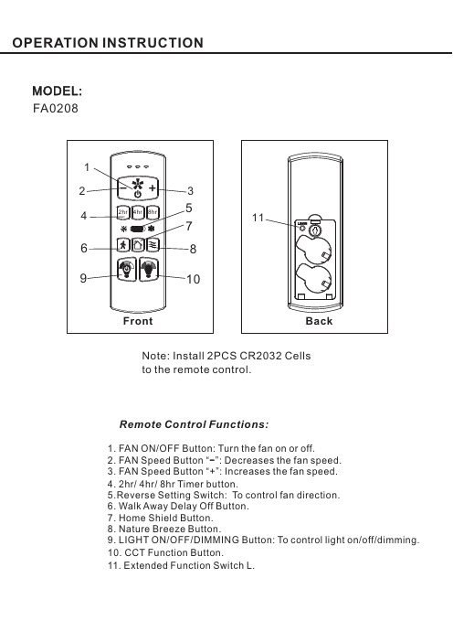
Remote Control Functions:MODEL:1.FAN ON/OFF Button:Turn the fan on or off 3.7.9.LIGHT ON/OFF/DIMMING Button:To control light on/off/dimming.10.11..Extended Function Switch L.2.FAN Speed Button “”:Decreases the fan speed.FAN Speed Button “+”:Increases the fan speed.Timer 5.6.Walk Away Delay Off Button.Home Shield Button.8.Nature Breeze Button.CCT Function .-248hr/hr/hr button Button .4.Reverse Setting Switch:To control fan direction.FA 0208Back11Note:Install 2PCS CR2032Cellsto the remote control.●Products shall be subject to any changes without additional notices due to DawnSun will keep innovation and optimization on the products.FCC STATEMENT1.This device complies with Part 15of the FCC Rules.Operation is subject to the following two conditions:(1)This device may not cause harmful interference This device must accept any interference received including interference that may cause undesired operation.2.Changes or modifications not expressly approved by the party responsible for compliance could void the user's authority to operate the equipment.(2),NOTE:This equipment has been tested and found to comply with the limits for a Class B digital device,pursuant to Part15of the FCC Rules.These limits are designed to provide reasonable protection against harmful interference in a residential installation.This equipment generates,uses and can radiate radio frequency energy and,if not installed and use in accordance with the instructions,may cause harmful interference to radio communications.However there is no guarantee that interference will not occur in a particular installation.If this equipment does cause harmful interference to radio or television reception,which can be determined by turning the equipment off and on,the user is encouraged to try to correct the interference by one or more of the following measures:1.Reorient or relocate the receiving antenna.2.Increase the separation between the equipment and receiver.3.Connect the equipment into an outlet on a circuit different from that to which the receiver is connected.4.Consult the dealer or an experienced radio/TV technician for help..,IC STATEMENTThis device complies with Industry Canada license-exempt RSS standard(s).Operation is subject to the following two conditions:this device may not cause harmful interference andthis device must accept any interference received,including interference that may cause undesired operation.Avis d'Industrie Canada (IC):Cet appareil est conforme avec Industrie Canada exempts de licence standard RSS (s).Son fonctionnement est soumisaux deux conditions suivantes cet appareil ne doit pas provoquer d interférences etcet appareil doit accepter toute interférence,y compris celles pouvant causer un mauvais fonctionnement de l'appareil.Votre appareil est conçu et fabriquépour ne pas dépasser les limites d'émission pour l'exposition àl énergie RF établie par le gouvernement du Canada (IC).Les informations sur votre appareil sont en fichier avec l'IC et peuvent être trouvées sous la section Affichage Grant de https://sms-sgs.ic.gc.ca/equipmentRechercher après la recherche sur l'IC pour votre appareil,qui se trouve sur le Àl arrière de l'appareil.(1),(2):(1)'(2)''Information concernant l'exposition àl énergie radiofréquence '。
远控同步操作规程(3篇)
第1篇一、概述远控同步操作规程是指通过远程控制手段,实现设备、系统或数据在不同地点、不同设备上同步操作的一系列规范和步骤。
本规程旨在确保远控操作的安全、高效和一致性,适用于各类远程操作场景,如远程办公、远程运维、远程教育等。
二、适用范围本规程适用于以下场景:1. 远程桌面操作;2. 远程服务器管理;3. 远程网络设备配置;4. 远程数据库管理;5. 远程应用程序操作;6. 其他需要远程同步操作的场合。
三、操作前的准备1. 人员准备:- 确保操作人员具备相应的专业技能和操作经验;- 操作人员应熟悉远控操作流程和注意事项;- 操作人员应接受相关安全培训。
2. 设备准备:- 确保远控设备和被控设备正常运行;- 检查网络连接是否稳定,带宽是否满足操作需求;- 确保远控软件版本兼容。
3. 环境准备:- 确保操作环境安全,无干扰因素;- 准备必要的操作手册、技术文档等参考资料。
四、操作步骤1. 登录远控软件:- 打开远控软件,输入用户名和密码登录;- 选择需要控制的设备或系统。
2. 连接被控设备:- 确认被控设备已开机,网络连接正常;- 在远控软件中选择“连接”或“远程桌面”等功能;- 输入被控设备的IP地址、端口等信息;- 等待连接建立。
3. 同步操作:- 根据操作需求,选择相应的同步操作方式,如文件传输、远程桌面、远程命令等;- 操作过程中,注意观察被控设备的响应情况,确保操作正确无误;- 如遇异常情况,及时中断操作,查找原因并解决。
4. 操作记录:- 对操作过程进行记录,包括操作时间、操作内容、操作结果等;- 操作记录应保存至安全位置,以便后续查询和审计。
5. 操作结束:- 操作完成后,关闭远控软件,断开与被控设备的连接;- 对被控设备进行重启或关闭操作,确保设备安全。
五、注意事项1. 安全防范:- 严格保密操作人员的用户名、密码等信息;- 定期更换操作密码,防止密码泄露;- 操作过程中,防止被恶意攻击或篡改。
远程遥控器操作指南说明书
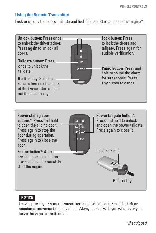
Using the Remote TransmitterLock or unlock the doors, tailgate and fuel-fill door. Start and stop the engine*.Built-in key*if equippedLeaving the key or remote transmitter in the vehicle can result in theft or accidental movement of the vehicle. Always take it with you whenever you leave the vehicle unattended.NOTICESmart Entry System*When you carry the remote transmitter (for example, in a pocket or purse)n Unlocking/Locking the DoorsTo unlock: With the vehicle off, grab the driver’s door handle to unlock the driver’s door. Grab the front passenger or rear door handle to unlock all doors and the tailgate.Door Lock ButtonButton*if equippedUnlocking/Locking the TailgateTo unlock: Press and hold the tailgate outer handle (under the tailgate TailgateHandleOuter Lock ButtonDoor OperationUse several methods to lock or unlock the doors.n Using the Lock TabTo unlock: When you unlock a front door using the lock tab, only that door unlocks.To lock: When you lock the driver’s door using the lock tab, all the doors and tailgate lock at the same time.n Using the Master Door LockSwitchTo unlock: Press the unlock side of the switch to unlock all doors and the tailgate.To lock: Press the lock side of the switch to lock all doors and the tailgate.To UnlockLock TabTo LockTo UnlockLock SwitchMaster Door To Lockn Childproof Door LocksThe childproof door locks prevent the rear doors from being opened from the inside, regardless of the position of the lock tab.Slide the lever in the rear door to the lock position and close the door.Open the door using the outer door handle.LockUnlockn Customizing Door Lock/Unlock SettingsCustomize the auto door-lock setting to your preference. Begin with the vehicle off.Models with color audioBegin with the vehicle stopped and the power mode set to e the p / q buttons to make selections, then press Enter.1.Press Home on the steering wheel.2.Select Settings.3.Select Vehicle Customization.4.Select Door/Window Setup.5.Select Auto Door Lock or Auto Door Unlock6.Select an option.àThe default for Auto Door Lock is With Vehicle Speed.àThe default for Auto Door Unlock is All Doors When Driver’s Door Opens.Goes back to the previous ENTER screen.Goes to home Enters the selected item.Outer HandleInner HandleCloseOpenn Power Sliding Doors*When the power mode is VEHICLEOFF (LOCK) or the remote engine start mode is active, the power slidingdoors operate when:•The power sliding door switch is ON (as shown) and•The power sliding door isunlocked and•The fuel-fill door is closed (fordriver’s side sliding door).OFF ONWhen the power mode is ON, the power sliding doors operate when:•The shift position is P and••*if equipped From the insidePress CLOSE to close the door.While a power sliding door is in operation, you can pull the handle again ton Walk Away Auto Lock*When you walk away from the vehicle while carrying the remote transmitter,the doors can automatically lock if the following conditions are met:•The remote transmitter is within a range of about 8 feet (2.5 m).•All doors are closed.•There is not an additional remote transmitter inside the vehicle.Follow these steps (see diagram):1.Carry the remote transmitter while you exit the vehicle. Stay near the vehicle until all the doors are all closed. Listen for a beep. The system is activated.2.Walk at least 5 feet (1.5 m) away.Listen for a beep and look for the lights to flash.The doors lock.To turn on this feature, follow the steps below:1.From the HOME screen, select Settings.2.Select Vehicle. The vehicle must be in Park (P).3.Select Keyless Access Setup.4.Select Walk Away Auto Lock.5.Select Enable.6.Select BACK to exit each menu.*if equippedPower Tailgate Operation*Use these methods to operate the power tailgate.n Power Tailgate Button The vehicle must be in Park (P) with all doors unlocked.Press and hold the power tailgate button on the dashboard until the tailgate starts to open. Press itagain to stop, or press and hold until it reverses.n Power Tailgate Inner ButtonPress the tailgate inner button to automatically close the tailgate.Press it again at any time to stop it.Press again to reverse the tailgate direction.Power Tailgate ButtonTailgate Inner Buttonn Manual OpeningPress and hold the tailgate outer handle longer than one second.The tailgate unlatches and you can open it manually.Outer HandleDo not push or pull on the power tailgate when it is being automatically opened or closed. Forcibly opening or closing the power tailgate while in operation can deform the tailgate frame.NOTICE。
向日葵智能远控遥控器用户手册说明书

向日葵智能远控遥控器用户手册V1.2.1202109181442声明Copyright ©2021上海贝锐信息科技股份有限公司版权所有,保留所有权利。
未经本公司明确书面许可,任何单位和个人不得擅自摘抄、复制本书内容的部分或全部,并不得以任何形式传播。
本手册所提到的产品规格和资讯仅供参考,如有内容更新,恕不另行通知。
除非有特殊约定,本手册仅作为使用指导,所作陈述均不构成任何形式的担保。
目录1 产品简介 (1)1.1 功能简介 (1)1.2 接口与按键展示 (1)1.3 指示灯状态说明 (2)1.4 产品规格 (2)2 使用步骤 (3)2.1 安装向日葵远程控制APP (3)2.2 App添加遥控器 (4)2.3匹配电器遥控器面板 (5)2.4自定义学习 (8)2.5快速匹配功能入口 (9)3 温馨提示 (10)6 常见问题 (10)1 产品简介1.1 功能简介向日葵智能远控遥控器是一款可以远程遥控传统红外电器的智能硬件。
用户将遥控器通过WiFi方式绑定到向日葵帐号后,并添加匹配遥控器的遥控面板,通过向日葵远程控制软件即可实现远程遥控红外电器,同一空间,1台遥控器即可遥控多台红外设备。
它精致轻巧,携带便捷,支持DC 5V/1A的方式接入供电;而且操作简单,通过WiFi联网,摆脱线材束缚,实现随时随地使用手机远程遥控红外电器。
1.2 接口与按键展示(1)输入:用于设备供电,规则DC 5V/1A;(2)复位按钮:短按可以点亮设备指示灯,长按5 秒后后可以重置设备;(3)指示灯:显示设备当前的状态,详情请见本文内容【1.3 指示灯状态说明】1.3 指示灯状态说明遥控器仅1个蓝色指示灯,标识设备当前工作状态蓝灯亮起:接通电源蓝灯闪烁:等待配置中配置过程中,蓝灯熄灭:正常连接网络手动短按一次复位按钮:蓝灯亮起1.4 产品规格产品型号KH1产品尺寸68mm*27.8mm(含防滑垫)产品重量约62g无线连接WiFi(2.4G)输入DC 5V/1A工作温度0-50℃工作湿度≤80%2 使用步骤2.1 安装向日葵远程控制APP接下来以安卓手机为例演示如何使用KH1实现远程遥控红外设备,下载并安装“向日葵远程控制”APP。
远控台的安装与操作

青海油田井下作业公司 试油测试大队
?5、液动防喷器的控制手柄都应有标识,不 准随意搬动。在待工工况下,远程控制台 控制环形防喷器的手柄置于中位,控制全 封闸板(剪切闸板)的换向阀手柄用限位 装置限制在中位,其他三通四通换向阀手 柄的倒向与所控制对象的开关状态一致。
青海油田井下作业公司 试油测试大队
青海油田井下作业公司 试油测试大队
岗位需求矩阵培训
远控台的安装与操作
青海油田井下作业公司 试油测试大队
1
前言
2
远程控制系统的安装ຫໍສະໝຸດ 3远程控制系统的使用
4
总结
一、前言:
青海油田井下作业公司 试油测试大队
(一)远控台的作用 ◆ 远控台是开关防喷器和液动闸阀的装置。 ◆ 它既要提供足够压力和排量的压力油,还要在平时把 这种液压能贮存起来 ◆ 开关防喷器时,通过控制阀件把液压油准确迅速地输
? 1、远控台应安装在面对修井机左侧距井口不少于 25m的专用活动房内,距防喷管线或压井管线不 小于2m,并保持不少于 2m的人行通道,周围 10m 内严禁堆放易燃、易爆、腐蚀物品。
青海油田井下作业公司 试油测试大队
?2、防喷器的液压控制管线束应整齐安放在 管排盒内,其中长出的部分应整齐的放在 远控台附近,管排盒与放喷管线的距离不 少于1m,车辆跨越处应装防碾压保护的过 桥盖板,严禁在管排盒上堆放杂物和以其 作为电焊接地线或在其上进行焊接作业, 在液控管线处还应设立高压警示标志。
?6、司钻控制台上不应安装操作剪切闸板的 控制阀。
青海油田井下作业公司 试油测试大队
三、远程控制系统的操作
1、使用压力继电器将 系统液压力达上限 (21±0.5MPa)
青海油田井下作业公司 试油测试大队
远程控制器RC-300用户手册说明书
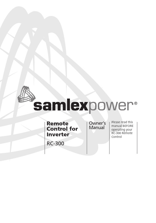
OWNER'S MANUAL | IndexSECTION 1Safety (3)SECTION 2Description (3)SECTION 3Layout of Controls, Indications& Dimensional Drawings (3)SECTION 4Installation (6)SECTION 5Operation (6)SECTION 6Specifications (7)SECTION 7Warranty (8)Disclaimer of LiabilityUNLESS SPECIFICALL Y AGREED TO IN WRITING, SAMLEX AMERICA, INC.:1. MAKES NO WARRANTY AS TO THE ACCURACY, SUFFICIENCY OR SUITABILITY OF ANY TECHNICAL OR OTHERINFORMATION PROVIDED IN ITS MANUALS OR OTHER DOCUMENTATION.2. ASSUMES NO RESPONSIBILITY OR LIABILITY FOR LOSSES, DAMAGES, COSTS OR EXPENSES, WHETHER SPECIAL,DIRECT, INDIRECT, CONSEQUENTIAL OR INCIDENTAL, WHICH MIGHT ARISE OUT OF THE USE OF SUCH INFORMATION.THE USE OF ANY SUCH INFORMATION WILL BE ENTIREL Y AT THE USERS RISK.Samlex America reserves the right to revise this document and to periodically make changes to the content hereof without obligation or organization of such revisions or changes.Copyright Notice/Notice of CopyrightCopyright © 2016 by Samlex America, Inc. All rights reserved. Permission to copy, distribute and/or modify this document is prohibited without express written permission by Samlex America, Inc.2 | SAMLEX AMERICA INC.SECTION 1 | SAFETY1.1 B efore using this Remote Control, please follow the Safety Instructionsgiven in the Owner’s Manual for the associated PST Series Inverters. SECTION 2 | DESCRIPTION2.1 R C-300 is a wired Remote Control that is compatible with PST Series Inverters(Please refer to Section 6 - Specifications for the list of inverters).2.3 I t is used to switch ON and switch OFF the inverter from a remote location.It also displays the operational status using LCD display and colored LEDs.It is provided with 25 ft / 7.62 meters of connecting cable set with RJ-50Modular Plugs (10P10C). The conductors of the cable set have crossed-over (rolled-over) connections on the two RJ-50 plugs.SECTION 3 | LAYOUT OF CONTROLS, INDICATIONS& DIMENSIONAL DRAWING3.1 F ig. 1 (page 4) shows the layout of controls and indications and dimen-sional drawing.3.2 ON/OFF ControlON/OFF Push Button (1) is used to switch ON and switch OFF the inverter. Every time the ON/OFF Push Button is pressed, a beep will be heard.This Remote Control will operate only after the inverter has been first turned ON using the local ON/OFF Switch on the inverter or using external ON/OFF control provided in the inverter.3.3 LCD DisplayLCD screen (3) is used to display the following 6 output parameters in a sequential loop as given below.The screen changes to show the successive parameter in a sequentialmanner every time the “Display Push Button” (2) is pressed (Sequence is: Screen1-2-3-4-5-6-1-2-3…)1. AC output voltage in Volts, V2. AC output current in Amps, A3. AC output frequency in Hertz, Hz4. Active AC output power in Watts, W - The display is limited to arange of 6W - 3500W5. Apparent Output Power in Volt Amps, VA6. Power Factor, PFSAMLEX AMERICA INC. | 34 | SAMLEX AMERICA INC.screen displays information as follows:• It takes 2 to 6 sec for booting / initialization. During this time, all the above 6 parameters will be displayed as “0”• If the load is > 6W, all the above 6 parameters will be available for display afterend of booting / initialization period•If the AC output power is less than 6W, parameters “AC output current in A”,“Active AC output power in Watts, W”, “Apparent Output AC Power in Volt Amps,VA” and “Power Factor , PF” will not be displayed (will be displayed as “0”). This isnecessary because at power output < 6W, the noise on the output side may be com-parable to the low value of the load and the logic may not be able to differentiatenoise from load and hence, may display wrong values for these parameters3.4 Power Saving / Sleep Mode in the LCD Display To save power, the LCD display will remain ON for 3 minutes from the time the Display Push Button (2) is pressed and will then switch OFF into Sleep Mode. To Front ViewOverall Depth: 25.5Back View8,58,51548Overall Depth:Front ViewBack View17R232,532,59880LEGEND1. Power ON/OFF Push Button2. Push Button to Change Display Screen3. LCD Screen4. LED - “Overload”5. LED - “Over Temp”6. LED - “Power”7. RJ-50 Modular JackNote: All dimensions in mmFig. 1 Remote Control RC-300 - Layout and Dimensional Drawing3.5 LED DisplayThe following LED displays are available:• Green LED (6) marked POWER. This LED will be lighted when the inverter is in ON condition. When the inverter is in OFF condition, this LED will not be lighted. ThisLED shows that DC input is available to the inverter and that the input section of theinverter is operating normally• Red LED (4) marked OVER LOAD. When lighted, it indicates that the AC output of the inverter has been shut down due to over load• Red LED (5) marked OVER TEMP. When lighted, it indicates that the AC output of the inverter has been shut down due to over temperature3.6 Pinout of RJ-50 Modular JackThe pinout of the RJ-50 Modular Jack (7) at the back of the RC-300 is given atFig. 2 below:Fig. 2 Remote Control RC-300 - Pinout of Modular Jack RJ-50The standard numbering system of the pins of a Modular Jack, when looking into the Jack, is from left to right. As the conductors of the cable are cross-connected (rolled-over), the pinouts at the Modular Jack in the inverter will be a mirror image of the pinout of the Modular Jack in the Remote Control as shown in T able 1 below:TABLE 1 – PIN OUT FOR MODULAR JACKSPinout of Modular Jackon the Remote Control as per Fig 2(1)Signal(2)Pinout of ModularJack on the inverter(See Note 1)(3)1LED "OVER TEMP"102LED "POWER ON"93Avcc84GND75TOGGLE66LED - “OVERLOAD"57Vcc48LCD - Data (B)39LCD - Data (A)210LCD - Ground1Note for T able 1:1. P in Nos of the Jack on the inverter (Column 3) are mirror image of Pin Nos on the Jack in the Remote (Column 1) due to crossed-over / rolled over connection of conductors.SAMLEX AMERICA INC. | 5SECTION 4 | INSTALLATION4.1 P lease refer to Fig. 1. The Remote Control can be flush mounted on a wallor a panel by making a suitable cut-out to accommodate the projection in the back.4.2 P lease ensure that the inverter is switched OFF before connecting RC-300to the inverter.4.3 C onnect one end of the cable set to the RJ-50 Modular Jack (7) at theback and the Remote and the other end to the RJ-50 Modular Jack on the inverter. Ensure that the connection is firm and the tab on the plug securely locks in the jack.SECTION 5 | OPERATIONNOTE:This Remote Control will operate only after the inverter has been first switched ON using the local ON/OFF Switch on the inverter or using the external ON/OFF control provided on the inverter.5.1 S witch ON the inverter using the local ON/OFF Switch on the inverter orusing external ON/OFF control provided on the inverter. Once the inverter turns ON, the operational status of the inverter will be displayed through the LCD screen (3, Fig 1) and LEDs (4, 5, 6; Fig 1).5.2 S ee under headings “LCD Display” (Section 3.3 and 3.4) and “LED Display”(Section 3.5) for information on the operating conditions. Please read"Troubleshooting Guide" of the Owner's Manual of the inverter for identify-ing abnormal conditions indicated by the LEDs.5.3 T he output of the inverter can be switched ON/OFF using the ON/OFF PushButton (1, Fig 1).5.4 No Load Current DrawAs stated above, the ON/OFF Switch on the inverter is required to be in ON condition for the Remote to operate. When the ON/OFF switch on the Remote Control is turned ON, all the circuitry inside the inverter becomes fully alive and the AC output is made available. In this condition, even when no load is being supplied (or, if a load is connected but has been switched OFF), the inverter draws a small amount of current from the batteries to keep the circuitry alive and is ready to deliver the required power on demand. This is called the “idle current” or the “no load current draw”. When the inverter is turned OFF using this Remote Control, some control circuitry is still alive in the inverter and will require very small current draw. Hence, when the load is not required to be operated, turn OFF the ON/OFF Switch on the inverter to prevent unnecessary current drain from the battery.6 | SAMLEX AMERICA INC.SECTION 6 | SPECIFICATIONSMODEL NUMBERS OF COMPATIBLE INVERTERS PST-1500-12, PST-1500-24, PST-1500-48 PST-2000-12, PST-2000-24PST-3000-12, PST-3000-24PST-300S-12E, PST-300S-24ECABLE SET RJ-50 (10P10C) with crossed-over / rolled-overconnections. Length = 25 ft / 7.62 meters OPERATING TEMPERATURE RANGE0 to 40°C / 32°F to 104°FDIMENSIONS (L X W X D)110 x 65 x 24.7 mm / 4.33 x 2.56 x 0.97 in Weight (Without cable / with cable)85 g / 256 g; 0.04 lb / 0.12 lbNOTE: Specifications are subject to change without noticeSAMLEX AMERICA INC. | 7SECTION 7 | WARRANTY2 YEAR LIMITED WARRANTYRC-300 Remote Control manufactured by Samlex America, Inc. (the “Warrantor“) is warranted to be free from defects in workmanship and materials under normal use and service. The warranty period is 2 years for the United States and Canada, and is in effect from the date of purchase by the user (the “Purchaser“).Warranty outside of the United States and Canada is limited to 6 months. For a warranty claim, the Purchaser should contact the place of purchase to obtain a Return Authorization Number.The defective part or unit should be returned at the Purchaser’s expense to the authorized location. A written statement describing the nature of the defect, the date of purchase, the place of purchase, and the Purchaser’s name, address and telephone number should also be included.If upon the Warrantor’s examination, the defect proves to be the result of defective material or workmanship, the equipment will be repaired or replaced at the Warrantor’s option without charge, and returned to the Purchaser at the Warrantor’s expense. (Contiguous US and Canada only)No refund of the purchase price will be granted to the Purchaser, unless the Warrantor is unable to remedy the defect after having a reasonable number of opportunitiesto do so. Warranty service shall be performed only by the Warrantor. Any attemptto remedy the defect by anyone other than the Warrantor shall render this warranty void. There shall be no warranty for defects or damages caused by faulty installation or hook-up, abuse or misuse of the equipment including exposure to excessive heat, salt or fresh water spray, or water immersion.No other express warranty is hereby given and there are no warranties which extend beyond those described herein. This warranty is expressly in lieu of any other expressed or implied warranties, including any implied warranty of merchantability, fitnessfor the ordinary purposes for which such goods are used, or fitness for a particular purpose, or any other obligations on the part of the Warrantor or its employees and representatives.There shall be no responsibility or liability whatsoever on the part of the Warrantor or its employees and representatives for injury to any persons, or damage to person or persons, or damage to property, or loss of income or profit, or any other consequential or resulting damage which may be claimed to have been incurred through the use or sale of the equipment, including any possible failure of malfunction of the equipment, or part thereof. The Warrantor assumes no liability for incidental or consequential damages of any kind.Samlex America Inc. (the “Warrantor”)8 | SAMLEX AMERICA INC.SAMLEX AMERICA INC. | 910 | SAMLEX AMERICA INC.NOTES:SAMLEX AMERICA INC. | 1111001-RC-300-0817。
远程控制台.原理及操作PPT

配置与设置
01
02
03
连接配置
用户需要配置远程控制台 与目标设备的连接参数, 如IP地址、端口号、连接 协议等。
界面设置
用户可以根据个人喜好调 整远程控制台的界面风格、 字体大小、颜色等设置。
权限管理
根据不同用户的角色和需 求,设置不同的权限级别, 限制用户对远程控制台功 能的访问和使用。
操作与监控
集中管理
可以同时管理多个设备,提高 工作效率。
安全可靠
数据传输加密,保证数据安全 。
远程控制台的应用场景
工业自动化
能源管理
ห้องสมุดไป่ตู้
交通监控
安全监控
远程监控和控制工厂设 备。
远程监控和管理电力、 燃气等能源供应。
远程监控和管理交通信 号、摄像头等设备。
远程监控和管理安全摄 像头、报警系统等设备。
远程控制台的发展历程
数据备份
定期对远程控制台的数据进行备 份,以防止数据丢失和意外情况 发生。
访问权限控制
用户身份验证
通过用户名、密码、动态令牌等方式对访问远程控制台的用户进行 身份验证。
权限分级
根据用户角色和职责,设置不同的访问权限级别,限制用户对远程 控制台的访问范围。
审计与日志记录
对远程控制台的访问活动进行记录和审计,以便追踪和监控异常行为。
02
多个服务器协同工作,共同提供服务,提高系统可扩展性和容
错性。
云架构
03
将计算和存储资源虚拟化,通过网络提供服务,灵活可配置,
便于管理和维护。
数据传输与处理
数据加密
采用加密算法对传输数据进行加密,确保数 据安全。
数据缓存
存储常用数据,提高访问速度。
远程监控平台使用简易说明
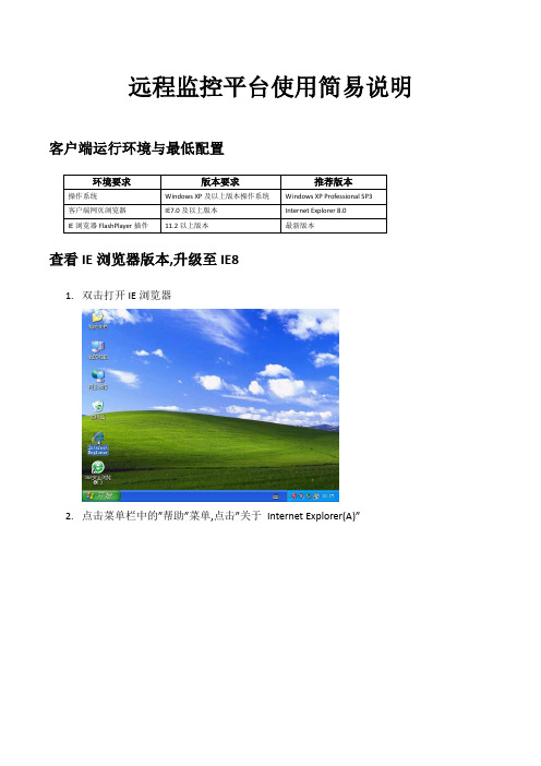
远程监控平台使用简易说明客户端运行环境与最低配置查看IE浏览器版本,升级至IE81.双击打开IE浏览器2.点击菜单栏中的”帮助”菜单,点击”关于Internet Explorer(A)”3.查看IE浏览器的版本如果不是Internet Explorer8,可以到微软官方网站下载安装Internet Explorer8,下载地址为:/action/mrtiex_FY12IE9StaPrdIE8WWpageforXPFNL_1?href=/action/mrtiex_FY12IE9StaPrdIE8WWpag eforXPFNL_1?href=/download/1/6/1/16174D37-73C1-4F76-A305-902E9D32BAC9/IE8-WindowsXP-x86-CHS.exeFlashPlayer的安装1.若您的浏览器中的FlashPlayer插件的版本过低,会出现如下提示,点击这里到官方网站免费下载最新的FlashPlayer For IE插件。
2.进入Adobe官方下载页面后,按照提示下载并安装最新版FlashPlayer插件,安装完成后需重启IE浏览器。
XFRtInfo实时信息系统使用操作1.在IE浏览器的地址栏中输入网址:/xfkj,并点击“注册新账号”按钮。
2.输入要注册的用户名(必须以邮箱地址作为用户名)和联系电话(可选填项),点击“确认注册”按钮。
3.看到注册成功的提示。
4.登录注册的邮箱地址,通过系统发送邮件中获得系统登录的用户名和密码。
5.初次登录系统后,建议修改初始密码并妥善保管,通过点击“设置”按钮修改密码。
6.本系统用户身份认证(Cookie)有效期默认为两个小时,在两个小时之内不对本系统有任何操作,身份认证将会失效,需要重新登录系统。
新建设备(这里以西门子PLC200为例)1.在导航栏的空白处点击鼠标反手键,在弹出菜单中点击新建按钮。
2.在弹出的新建窗口中,填入新建设备的名称并在类别下拉类别树中选择一个新建的类别,这里以新建一个西门子PLC200为例,依次展开“设备”节点->“仪器仪表设备”节点->“PLC可编程控制器”节点选择“SiemensPLC200”。
监控操作台的使用流程高清
监控操作台的使用流程高清1. 介绍监控操作台是一种用于监控系统运行并进行管理的工具。
它提供了实时监控、告警管理、日志分析等功能,帮助用户快速定位和解决问题,保障系统运行的稳定性和安全性。
2. 使用步骤下面将介绍监控操作台的使用流程,以帮助用户快速上手并熟悉其功能。
2.1 登录操作台首先,打开监控操作台的登录页面。
输入正确的用户名和密码,点击登录按钮进行登录。
2.2 首页概览成功登录后,进入监控操作台的首页。
首页概览提供了系统的整体状态和重要指标的展示,以便用户一目了然地了解系统的运行情况。
2.3 实时监控点击导航栏中的实时监控,进入实时监控页面。
实时监控页面展示了系统的各项实时指标,用户可以通过图表、表格等方式查看数据,并根据需要进行筛选和排序。
同时,实时监控页面还支持自定义监控视图,用户可以根据自己的需求创建和管理监控视图。
2.4 告警管理点击导航栏中的告警管理,进入告警管理页面。
告警管理页面展示了系统的告警信息,包括告警级别、告警内容等。
用户可以对告警信息进行查看、确认和处理,同时还可以根据不同的条件进行筛选和排序。
2.5 日志分析点击导航栏中的日志分析,进入日志分析页面。
日志分析页面展示了系统的日志信息,用户可以根据关键字、时间范围等条件进行日志搜索,并对搜索结果进行查看和分析。
同时,日志分析页面还支持日志的导出和导入,以方便用户进行更深入的分析和管理。
2.6 系统设置点击导航栏中的系统设置,进入系统设置页面。
系统设置页面提供了对监控操作台的一些基本配置项进行管理,包括用户管理、权限设置、数据源配置等。
用户可以根据需要对这些配置项进行修改和调整,以满足自己的需求。
3. 总结通过以上步骤,用户可以快速上手并熟悉监控操作台的使用流程。
监控操作台提供了实时监控、告警管理、日志分析等功能,帮助用户实时掌握系统的运行状况,并及时发现和解决问题,以保障系统的稳定性和安全性。
希望本文档对用户在使用监控操作台时有所帮助。
监控操作台的使用流程教程
监控操作台的使用流程教程简介监控操作台是一种用于监控和管理网络设备和应用程序的工具。
它提供了一个集中化的界面,通过该界面可以实时查看设备状态、收集和分析日志、配置和调整监控策略等。
本文档将介绍监控操作台的基本使用流程,帮助用户快速上手。
步骤一:登录操作台1.在浏览器中打开监控操作台的网址。
2.输入用户名和密码,并点击登录按钮进行登录。
3.如果您忘记了密码,可以点击“忘记密码”链接进行密码重置。
步骤二:浏览仪表盘1.登录后,您将进入仪表盘界面,这是监控操作台的主界面。
2.在仪表盘上,您可以看到各种监控指标的图表和数据。
3.您可以使用仪表盘的搜索功能来查找特定指标。
4.您还可以根据需求自定义显示的图表和指标。
步骤三:查看设备状态1.在左侧的导航栏中,选择“设备状态”选项。
2.在设备状态页面,您将看到设备的在线状态、CPU利用率、内存使用率等信息。
3.您可以通过设备状态页面快速了解设备的健康状况,并采取相应措施。
步骤四:配置监控策略1.在左侧的导航栏中,选择“监控策略”选项。
2.在监控策略页面,您可以为每个设备或应用程序配置监控策略。
3.您可以选择监控的指标和阀值,设置告警方式等。
4.您还可以为不同的设备或应用程序创建不同的监控策略。
步骤五:分析日志信息1.在左侧的导航栏中,选择“日志分析”选项。
2.在日志分析页面,您可以查看设备生成的日志信息。
3.您可以使用过滤器和关键字搜索来快速定位需要的日志信息。
4.您还可以将日志信息导出到本地进行进一步分析和处理。
步骤六:查看报警信息1.在左侧的导航栏中,选择“报警信息”选项。
2.在报警信息页面,您可以查看设备和应用程序的报警信息。
3.您可以按照时间、设备、级别等条件进行筛选和排序。
4.您还可以自定义报警规则和通知方式,以便及时处理报警情况。
步骤七:管理用户权限1.在左侧的导航栏中,选择“用户管理”选项。
2.在用户管理页面,您可以添加、修改和删除用户账号。
3.您可以为每个用户分配不同的权限和角色。
远控机构操作规程(3篇)
第1篇一、目的为确保远控机构的安全、稳定、高效运行,规范操作流程,提高工作效率,特制定本规程。
二、适用范围本规程适用于所有使用远控机构的单位和个人。
三、操作人员要求1. 操作人员应具备一定的计算机操作技能,熟悉远控机构的操作流程。
2. 操作人员应了解远控机构的基本原理、性能特点、维护保养知识。
3. 操作人员应严格遵守本规程,确保远控机构的安全、稳定、高效运行。
四、操作流程1. 启动远控机构(1)开启电源,确保远控机构各部件正常工作。
(2)登录远控机构,进入操作界面。
(3)检查远控机构各项参数设置是否正确,如有异常,及时调整。
2. 操作远控机构(1)根据实际需求,选择合适的操作模式(手动、自动、半自动等)。
(2)按照操作界面提示,进行相应操作。
(3)操作过程中,密切关注远控机构运行状态,发现异常情况,立即采取措施。
3. 停止远控机构(1)确认操作任务已完成,关闭操作模式。
(2)退出操作界面,关闭远控机构。
4. 维护保养(1)定期检查远控机构各部件,确保其正常工作。
(2)清洁远控机构,保持其整洁。
(3)定期进行保养,确保远控机构性能稳定。
五、注意事项1. 操作过程中,严禁操作人员擅自离开岗位,确保远控机构安全稳定运行。
2. 操作人员应严格遵守操作规程,不得擅自更改参数设置。
3. 远控机构运行过程中,如发现异常情况,应立即停机检查,排除故障后方可继续运行。
4. 远控机构维护保养工作应由专业人员负责,非专业人员不得擅自进行维修。
5. 远控机构操作人员应定期参加培训,提高操作技能和应急处理能力。
六、责任1. 操作人员负责本规程的执行,确保远控机构安全、稳定、高效运行。
2. 维护保养人员负责远控机构的日常维护保养工作,确保其性能稳定。
3. 领导部门负责监督本规程的执行,对违规操作行为进行严肃处理。
本规程自发布之日起实施,如遇特殊情况,可根据实际情况进行修订。
第2篇一、目的为确保远控机构安全、稳定、高效地运行,提高工作效率,保障生产安全,特制定本规程。
远程遥控操作平台

网络安全:保障数据传输安全
▪ 入侵检测与防御系统(IDS/IPS)
1.部署IDS/IPS系统,实时监测网络异常行为。 2.分析网络流量数据,发现潜在安全隐患。 3.及时响应并处置安全事件,防止攻击扩散。 入侵检测与防御系统(IDS/IPS)是网络安全的重要组成部分 。通过部署IDS/IPS系统,可以实时监测网络异常行为,分析 网络流量数据,发现潜在的安全隐患。同时,及时响应并处置 安全事件,可以防止攻击扩散,减少损失。
远程遥控操作平台
功能模块:平台的主要功能介绍
功能模块:平台的主要功能介绍
▪ 远程操控
1.实时远程控制:用户可通过网络对操作平台进行实时远程控 制,实现设备的即时操作和调整。 2.安全可靠:采用先进的加密技术和安全协议,确保远程操控 过程中的数据安全性和隐私保护。 3.高效稳定:具备高效稳定的远程操控性能,确保用户可以随 时随地进行设备控制,提高工作效率。
▪ 降低操作风险
1.远程遥控操作可以在保证人员安全的前提下,进行高风险、高难度的操作,降低 了操作风险。 2.通过远程遥控操作,可以避免现场操作人员受到意外伤害,保障人身安全。 3.远程遥控操作可以减少现场操作带来的设备损坏和损失,降低了经济成本。
引言:远程遥控操作的重要性
▪ 拓宽操作领域
1.远程遥控操作可以应用于各种领域,如航空航天、海洋探测 、危险品处理等,拓宽了操作领域。 2.通过远程遥控操作,可以实现许多人工现场操作难以实现的 任务,扩大了操作范围。 3.远程遥控操作可以与人工智能、机器学习等技术相结合,进 一步拓展应用领域和范围。
▪ 数据架构设计
1.数据架构设计了高效、稳定、安全的数据存储和处理系统, 能够处理大量的遥控操作数据。 2.数据架构注重数据的实时性和历史数据的可追溯性,能够实 时监控遥控操作的状态,同时能够查询历史操作记录,为数据 分析提供支持。
操作台使用方法
操作台使用方法
一、操作台使用方法
1、安装驱动程序
在使用操作台操作系统之前,首先要安装驱动程序。
驱动程序是操作系统与硬件设备之间的桥梁,是操作系统和硬件设备能够进行对话的媒介,在操作台操作系统中,驱动程序是必不可少的。
可以从各类计算机网站上下载相应的驱动程序,如果有的硬件设备有介绍文档,就先仔细阅读。
将驱动程序安装在操作台操作系统的硬件设备上。
一般情况下,双击安装文件即可完成安装,如果是第三方的驱动程序,可能会有一些特殊操作,需要按照说明文档步骤进行操作。
2、使用操作台
操作台是一种特殊的操作系统,它可以将操作系统和应用程序分离,可以保护用户的数据安全,在操作台中可以安装操作系统和应用程序,可以使用操作台进行系统的安全管理、进程管理、更新操作系统。
使用操作台时,需要先确保操作台的安全性,如果是第一次使用,需要先将操作台进行更新,以便于有效的保护系统安全。
有时候可能要在操作台上安装应用程序,可以将安装文件上传到操作台,进行安装。
如果用到的应用程序多,可以将操作台上的应用程序进行分类管理,这样可以有效的管理应用程序。
3、定期检查操作台
操作台的主要目的是为了保护系统,所以在使用操作台时要定期
检查操作台,定期扫描硬盘,删除垃圾文件,防止系统受到病毒侵害,同时定期更新操作台,确保操作台及时的得到更新信息,以便于具有较好的运行效果。
4、备份操作台
在使用操作台时,要定期进行备份,以防止系统出现意外的损坏,并将备份文件储存在安全的位置,以便于在需要时可以及时恢复正常的运行状态。
总之,使用操作台时要注意安全问题,才能有效的保证操作台的稳定性,保护系统安全,确保正常的运行。
- 1、下载文档前请自行甄别文档内容的完整性,平台不提供额外的编辑、内容补充、找答案等附加服务。
- 2、"仅部分预览"的文档,不可在线预览部分如存在完整性等问题,可反馈申请退款(可完整预览的文档不适用该条件!)。
- 3、如文档侵犯您的权益,请联系客服反馈,我们会尽快为您处理(人工客服工作时间:9:00-18:30)。
远控操作台使用说明太原矿山机器集团有限公司
个按钮是用来对采煤机进行远端操作的。
为了防止误操作远程按钮,对远端按钮加锁处理,远程操作前先解锁。
远控显示。
此时操作面板上的采煤机控制键采煤机动作。
在解锁状态下,再按一次解锁键解锁显示消失,操作台控制键失去作用。
在解锁状态30秒内不操作按钮,解锁显示自动消失,按钮自动加锁。
若要关闭远程控制解锁、远控状态按一次*键,采煤机画面提示请关闭远程控制,采煤机司机取消允许远控,远控显示消失。
