热电偶安装手册中英文
热电偶安装手册(中英文)
WR系列热电偶WR Series ThermocoupleWZ系列热电阻WR Series Thermocouple使用安装手册Installation & Operation Manual安徽天康(集团)股份有限公司Anhui Tiankang (Group) Shares Co., Ltd目录Index1、概述General Description (1)2、工作原理Operation Theory (1)3、结构Configuration (2)4、主要技术参数Main Technical Parameters (3)5、安装及使用Installation & Operation (5)6、可能发生的故障及维修Possible Troubles & Maintenance (7)7、运输及储存Transportation & Storage (8)8、订货须知Notices in Ordering (8)9、型号命名Type Naming (9)1、概述General Description工业用热电偶作为温度测量和调节的传感器,通常与显示仪表等配套,以直接测量各种生产过程中-40~1600℃液体、蒸汽和气体介质以及固体表面温度;As sensor for temperature measuring and regulation, industrial-purpose thermocouple is usually connected with display meter and other meters to directly measure temperature of liquid, vapor, gas and solid surface ranging from -40℃to 1600℃.工业用热电阻作为温度测量和调节的传感器,通常与显示仪表等配套,以直接测量各种生产过程中-200~500℃液体、蒸汽和气体介质以及固体表面温度。
EMERSON 热电阻和热电偶组件 说明书
参考手册00809-0306-2654,修订版 BA2009 年 9 月热电阻和热电偶组件参考手册参考手册00809-0306-2654,修订版 BA2009 年 9 月热电阻和热电偶 电阻温度计和热电偶组件的安装建议注意操作产品前,请阅读本手册。
为了个人和系统安全以及实现最佳产品性能,请务必在安装、使用和维护本产品前透彻地理解手册内容。
有关更多详细信息,请联系当地的罗斯蒙特代表。
参考手册00809-0306-2654,修订版 BA2009 年 9 月热电阻和热电偶/rosemount 目录第 1简介如何使用本手册 . . . . . . . . . . . . . . . . . . . . . . . . . . . . . . . . . . . . . . . . . .1-1安全消息 . . . . . . . . . . . . . . . . . . . . . . . . . . . . . . . . . . . . . . . . . . . . . . .1-1第 2使用电阻温度计测量温度描述和测量原理 . . . . . . . . . . . . . . . . . . . . . . . . . . . . . . . . . . . . . . . . . .2-1结构 . . . . . . . . . . . . . . . . . . . . . . . . . . . . . . . . . . . . . . . . . . . . . . . . . . .2-1连接方法 . . . . . . . . . . . . . . . . . . . . . . . . . . . . . . . . . . . . . . . . . . . . . . .2-3应用领域 . . . . . . . . . . . . . . . . . . . . . . . . . . . . . . . . . . . . . . . . . . . . . . .2-4第 3使用热电偶测量温度描述和测量原理 . . . . . . . . . . . . . . . . . . . . . . . . . . . . . . . . . . . . . . . . . .3-1保护管的安装. . . . . . . . . . . . . . . . . . . . . . . . . . . . . . . . . . . . . . . . . . . .3-3导线和连接件. . . . . . . . . . . . . . . . . . . . . . . . . . . . . . . . . . . . . . . . . . . .3-3应用领域 . . . . . . . . . . . . . . . . . . . . . . . . . . . . . . . . . . . . . . . . . . . . . . .3-3第 4外壳组件规则和说明. . . . . . . . . . . . . . . . . . . . . . . . . . . . . . . . . . . . . . . . . . . . . .4-1应力 . . . . . . . . . . . . . . . . . . . . . . . . . . . . . . . . . . . . . . . . . . . . . . . .4-1扭矩 . . . . . . . . . . . . . . . . . . . . . . . . . . . . . . . . . . . . . . . . . . . . . . . .4-1外壳组件. . . . . . . . . . . . . . . . . . . . . . . . . . . . . . . . . . . . . . . . . . . . .4-1陶瓷外壳安装 . . . . . . . . . . . . . . . . . . . . . . . . . . . . . . . . . . . . . . . . .4-2变送器连接 . . . . . . . . . . . . . . . . . . . . . . . . . . . . . . . . . . . . . . . . . . .4-2附录 A基本值的公差限值附录 B热电偶的公差限值参考手册00809-0306-2654,修订版 BA 热电阻和热电偶2009 年 9 月目录-2参考手册00809-0306-2654,修订版 BA2009 年 9 月热电阻和热电偶第1部分简介如何使用本手册. . . . . . . . . . . . . . . . . . . . . . .第 1-1 页安全消息. . . . . . . . . . . . . . . . . . . . . . . . . .第 1-1 页如何使用本手册本手册为使用罗斯蒙特 1075 系列提供安装、组态、故障排除和其他程序的信息。
热电偶温度传感器中英文对照外文翻译文献

中英文对照外文翻译文献(文档含英文原文和中文翻译)外文翻译:Thermocouple Temperatur sensorIntroduction to ThermocouplesThe thermocouple is one of the simplest of all sensors. It consists of two wires of dissimilar metals joined near the measurement point. The output is a small voltage measured between the two wires.While appealingly simple in concept, the theory behind the thermocouple is subtle, the basics of which need to be understood for the most effective use of the sensor.Thermocouple theoryA thermocouple circuit has at least two junctions: the measurement junction and a reference junction. Typically, the reference junction is created where the two wires connect to the measuring device. This second junction it is really two junctions: one for each of the two wires, but because they are assumed to be at the same temperature (isothermal) they are considered as one (thermal) junction. It is the point where the metals change - from the thermocouple metals to what ever metals are used in the measuring device - typically copper.The output voltage is related to the temperature difference between the measurement and the reference junctions. This is phenomena is known as the Seebeck effect. (See the Thermocouple Calculator to get a feel for the magnitude of the Seebeck voltage). The Seebeck effect generates a small voltage along the length of a wire, and is greatest where the temperature gradient is greatest. If the circuit is of wire of identical material, then they will generate identical but opposite Seebeck voltages which will cancel. However, if the wire metals are different the Seebeck voltages will be different and will not cancel.In practice the Seebeck voltage is made up of two components: the Peltiervoltage generated at the junctions, plus the Thomson voltage generated in the wires by the temperature gradient.The Peltier voltage is proportional to the temperature of each junction while the Thomson voltage is proportional to the square of the temperature difference between the two junctions. It is the Thomson voltage that accounts for most of the observed voltage and non-linearity in thermocouple response.Each thermocouple type has its characteristic Seebeck voltage curve. The curve is dependent on the metals, their purity, their homogeneity and their crystal structure. In the case of alloys, the ratio of constituents and their distribution in the wire is also important. These potential inhomogeneous characteristics of metal are why thick wire thermocouples can be more accurate in high temperature applications, when the thermocouple metals and their impurities become more mobile by diffusion.The practical considerations of thermocouplesThe above theory of thermocouple operation has important practical implications that are well worth understanding:1. A third metal may be introduced into a thermocouple circuit and have no impact, provided that both ends are at the same temperature. This means that the thermocouple measurement junction may be soldered, brazed or welded without affecting the thermocouple's calibration, as long as there is no net temperature gradient along the third metal.Further, if the measuring circuit metal (usually copper) is different to that of the thermocouple, then provided the temperature of the two connecting terminals is the same and known, the reading will not be affected by the presence of copper.2. The thermocouple's output is generated by the temperature gradient along the wires and not at the junctions as is commonly believed. Therefore it is important that the quality of the wire be maintained where temperature gradients exists. Wire quality can be compromised by contamination from its operating environment and the insulating material. For temperatures below 400°C, contamination of insulated wires is generally not a problem. At temperatures above 1000°C, the choice of insulationand sheath materials, as well as the wire thickness, become critical to the calibration stability of the thermocouple.The fact that a thermocouple's output is not generated at the junction should redirect attention to other potential problem areas.3. The voltage generated by a thermocouple is a function of the temperature difference between the measurement and reference junctions. Traditionally the reference junction was held at 0°C by an ice bath:The ice bath is now considered impractical and is replace by a reference junction compensation arrangement. This can be accomplished by measuring the reference junction temperature with an alternate temperature sensor (typically an RTD or thermistor) and applying a correcting voltage to the measured thermocouple voltage before scaling to temperature.The correction can be done electrically in hardware or mathematically in software. The software method is preferred as it is universal to all thermocouple types (provided the characteristics are known) and it allows for the correction of the small non-linearity over the reference temperature range.4. The low-level output from thermocouples (typically 50mV full scale) requires that care be taken to avoid electrical interference from motors, power cable, transformers and radio signal pickup. Twisting the thermocouple wire pair (say 1 twist per 10 cm) can greatly reduce magnetic field pickup. Using shielded cable or running wires in metal conduit can reduce electric field pickup. The measuring device should provide signal filtering, either in hardware or by software, with strong rejection of the line frequency (50/60 Hz) and its harmonics.5. The operating environment of the thermocouple needs to be considered. Exposure to oxidizing or reducing atmospheres at high temperature can significantly degrade some thermocouples. Thermocouples containing rhodium (B,R and S types) are not suitable under neutron radiation.The advantages and disadvantages of thermocouplesBecause of their physical characteristics, thermocouples are the preferred methodof temperature measurement in many applications. They can be very rugged, are immune to shock and vibration, are useful over a wide temperature range, are simple to manufactured, require no excitation power, there is no self heating and they can be made very small. No other temperature sensor provides this degree of versatility.Thermocouples are wonderful sensors to experiment with because of their robustness, wide temperature range and unique properties.On the down side, the thermocouple produces a relative low output signal that is non-linear. These characteristics require a sensitive and stable measuring device that is able provide reference junction compensation and linearization.Also the low signal level demands that a higher level of care be taken when installing to minimise potential noise sources.The measuring hardware requires good noise rejection capability. Ground loops can be a problem with non-isolated systems, unless the common mode range and rejection is adequate.Types of thermocoupleAbout 13 'standard' thermocouple types are commonly used. Eight have been given an internationally recognised letter type designators. The letter type designator refers to the emf table, not the composition of the metals - so any thermocouple that matches the emf table within the defined tolerances may receive that table's letter designator.Some of the non-recognised thermocouples may excel in particular niche applications and have gained a degree of acceptance for this reason, as well as due to effective marketing by the alloy manufacturer. Some of these have been given letter type designators by their manufacturers that have been partially accepted by industry.Each thermocouple type has characteristics that can be matched to applications. Industry generally prefers K and N types because of their suitability to high temperatures, while others often prefer the T type due to its sensitivity, low cost and ease of use.A table of standard thermocouple types is presented below. The table also showsthe temperature range for extension grade wire in brackets.Accuracy of thermocouplesThermocouples will function over a wide temperature range - from near absolute zero to their melting point, however they are normally only characterized over their stable range. Thermocouple accuracy is a difficult subject due to a range of factors. In principal and in practice a thermocouple can achieve excellent results (that is, significantly better than the above table indicates) if calibrated, used well below its nominal upper temperature limit and if protected from harsh atmospheres. At higher temperatures it is often better to use a heavier gauge of wire in order to maintain stability (Wire Gauge below).As mentioned previously, the temperature and voltage scales were redefined in 1990. The eight main thermocouple types - B, E, J, K, N, R, S and T - were re-characterised in 1993 to reflect the scale changes. (See: NIST Monograph 175 for details). The remaining types: C, D, G, L, M, P and U appear to have been informally re-characterised.Try the thermocouple calculator. It allows you the determine the temperature by knowing the measured voltage and the reference junction temperature.Thermocouple wire gradesThere are different grades of thermocouple wire. The principal divisions are between measurement grades and extension grades. The measurement grade has the highest purity and should be used where the temperature gradient is significant. The standard measurement grade (Class 2) is most commonly used. Special measurement grades (Class 1) are available with accuracy about twice the standard measurement grades.The extension thermocouple wire grades are designed for connecting the thermocouple to the measuring device. The extension wire may be of different metals to the measurement grade, but are chosen to have a matching response over a much reduced temperature range - typically -40°C to 120°C. The reason for using extension wire is reduced cost - they can be 20% to 30% of the cost of equivalent measurementgrades. Further cost savings are possible by using thinnergauge extension wire and a lower temperature rated insulation.Note: When temperatures within the extension wire's rating are being measured, it is OK to use the extension wire for the entire circuit. This is frequently done with T type extension wire, which is accurate over the -60 to 100°C range.Thermocouple wire gaugeAt high temperatures, thermocouple wire can under go irreversible changes in the form of modified crystal structure, selective migration of alloy components and chemical changes originating from the surface metal reacting to the surrounding environment. With some types, mechanical stress and cycling can also induce changes.Increasing the diameter of the wire where it is exposed to the high temperatures can reduce the impact of these effects.The following table can be used as a very approximate guide to wire gauge:At these higher temperatures, the thermocouple wire should be protected as much as possible from hostile gases. Reducing or oxidizing gases can corrode some thermocouple wire very quickly. Remember, the purity of the thermocouple wire is most important where the temperature gradients are greatest. It is with this part of the thermocouple wiring where the most care must be taken.Other sources of wire contamination include the mineral packing material and the protective metal sheath. Metallic vapour diffusion can be significant problem at high temperatures. Platinum wires should only be used inside a nonmetallic sheath, such as high-purity alumna.Neutron radiation (as in a nuclear reactor) can have significant permanent impact on the thermocouple calibration. This is due to the transformation of metals to different elements.High temperature measurement is very difficult in some situations. In preference, use non-contact methods. However this is not always possible, as the site of temperature measurement is not always visible to these types of sensors.Colour coding of thermocouple wireThe colour coding of thermocouple wire is something of a nightmare! There are at least seven different standards. There are some inconsistencies between standards, which seem to have been designed to confuse. For example the colour red in the USA standard is always used for the negative lead, while in German and Japanese standards it is always the positive lead. The British, French and International standards avoid the use of red entirely!Thermocouple mountingThere are four common ways in which thermocouples are mounted with in a stainless steel or Inconel sheath and electrically insulated with mineral oxides. Each of the methods has its advantages and disadvantages.Sealed and Isolated from Sheath: Good relatively trouble-free arrangement. The principal reason for not using this arrangement for all applications is its sluggish response time - the typical time constant is 75 secondsSealed and Grounded to Sheath: Can cause ground loops and other noise injection, but provides a reasonable time constant (40 seconds) and a sealed enclosure.Exposed Bead: Faster response time constant (typically 15 seconds), but lacks mechanical and chemical protection, and electrical isolation from material being measured. The porous insulating mineral oxides must be sealedExposed Fast Response: Fastest response time constant, typically 2 seconds but with fine gauge of junction wire the time constant can be 10-100 ms. In addition to problems of the exposed bead type, the protruding and light construction makes the thermocouple more prone to physical damage.Thermocouple compensation and linearizationAs mentioned above, it is possible to provide reference junction compensation in hardware or in software. The principal is the same in both cases: adding a correction voltage to the thermocouple output voltage, proportional to the reference junction temperature. To this end, the connection point of the thermocouple wires to the measuring device (i.e. where the thermocouple materials change to the copper of thecircuit electronics) must be monitored by a sensor. This area must be design to be isothermal, so that the sensor accurately tracks both reference junction temperatures.The hardware solution is simple but not always as easy to implement as one might expect.The circuit needs to be designed for a specific thermocouple type and hence lacks the flexibility of the software approach.The software compensation technique simplifies the hardware requirement, by eliminating the reference sensor amplifier and summing circuit (although a multiplexer may be required).The software algorithm to process the signals needs to be carefully written. A sample algorithm details the process.A good resource for thermocouple emf tables and coefficients is at the US Commerce Dept's NIST web site. It covers the B, E, J, K, N, R, S and T types.The thermocouple as a heat pumpThe thermocouple can function in reverse. If a current is passed through a thermocouple circuit, one junction will cool and the other warm. This is known as the Peltier Effect and is used in small cooling systems. The effect can be demonstrated by alternately passing a current through a thermocouple circuit and then quickly measuring the circuit's Seebeck voltage. This process has been used, with very fine thermocouple wire (0.025 mm with about a 10 mA current), to measure humidity by ensuring the cooled junction drops below the air's dew point. This causes condensation to form on the cooled junction. The junction is allowed to return to ambient, with the temperature curve showing an inflection at the dew point caused by the latent heat of vaporization.Measuring temperature differencesThermocouples are excellent for measuring temperatures differences, such as the wet bulb depression in measuring humidity. Sensitivity can be enhanced by constructing a thermopile - a number of thermocouple circuits in series.In the above example, the thermopile output is proportional to the temperaturedifference T1 - T2, with a sensitivity three times that of a single junction pair. In practice, thermopiles with two to hundreds of junctions are used in radiometers, heat flux sensors, flow sensors and humidity sensors. The thermocouple materials can be in wire form, but also printed or etched as foils and even electroplated.An excellent example of the thermopile is in the heat flux sensors manufactured by Hukseflux Thermal Sensors. Also see RdF Corp. and Exergen Corp.The thermocouple is unique in its ability to directly measure a temperature difference. Other sensor types require a pair of closely matched sensors to ensure tracking over the entire operational temperature range.The thermoelectric generatorWhile the Seebeck voltage is very small (in the order of 10-70μV/°C), if the circuit's electrical resistance is low (thick, short wires), then large currents are possible (e.g. many amperes). An efficiency trade-off of electrical resistance (as small as possible) and thermal resistance (as large as possible) between the junctions is the major issue. Generally, electrical and thermal resistances trend together with different materials. The output voltage can be increased by wiring as a thermopile.The thermoelectric generator has found its best-known application as the power source in some spacecraft. A radioactive material, such as plutonium, generates heat and cooling is provided by heat radiation into space. Such an atomic power source can reliably provide many tens of watts of power for years. The fact that atomic generators are highly radioactive prevents their wider application.译文:热电偶温度传感器热电偶的定义热电偶是最简单的传感器之一。
S96 多点式挠性热电偶安装手册
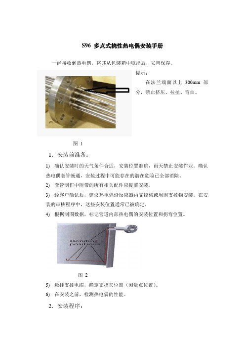
S96 多点式挠性热电偶安装手册一经接收到热电偶,将其从包装箱中取出后,妥善保存。
提示:在法兰端面以上300mm部分,禁止挤压、拉扯、弯曲。
图11.安装前准备:1)确认安装时的天气条件合适,安装位置准确,雨天禁止安装作业。
确认热电偶套管畅通,安装过程中可能存在的潜在危险已全部消除。
2)套管制作中附带的所有相关配件应提前安装。
3)经客户确认后,建议热电偶沿反应器内支撑梁或周围支撑物安装。
在安装的审核程序中,这些安装位置通常已被确定。
4)根据制图数据,标记管道内部热电偶的安装位置和拐弯位置。
图25)悬挂支撑电缆,确定支撑夹位置(测量点位置)。
6)在安装之前,检测热电偶的性能。
2.安装程序:1)在S96型热电偶安入反应器前,必须将其整顺。
2)在装入的热电偶上标记每一个拐点的位置。
3)标记完后,将多点式热电偶置于管嘴前。
图3:不要让四个支撑接触热电偶。
4)开始安装多点式热电偶。
将图2整个装置装入套管中,在装之前不要忘了提前将两个法兰之间的垫片装上。
5)法兰正确安装后紧固。
6)在反应器内部,热电偶的每一次弯曲标记都要很明显。
(热电偶的最小弯曲半径: 100 mm.)。
同上,将所有热电偶安到各自的位置。
7)将热电偶的顶部固定好后,其他的按照同样的过程安装(参照安装图及安装计划)。
8)一旦所有的热电偶全部装上后,应即可将它们通过支撑夹固定住(参照安装图)。
9)安装完毕后,再次检查热电偶的性能。
所有的脚手架,要求的设备及全体人员必须在安装之前到达安装指定位置,这样以来可减少不必要的等候和委托人的费用。
Yorkshire 加热系统 部件安装说明书
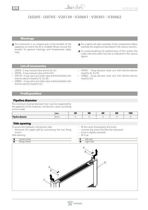
I 20205 - I20705 - V20139 - V20661 - V30361 - V30662W arningsT his instruction is an integral part of the booklet of theappliance on which the kit is installed. Please consult this booklet for general warnings and fundamental safety rules.For a rapid and right assembly of the components follow carefully the sequences described in the various sections.To avoid penalising the performance of the system the water inlet and outlet must be as indicated in the various figures.L ist of accessories• I20205 - 2-way manual valve unit for SL, SLI • I20705 - 2-way manual valve unit for SLS• V20139 - 2-way valve unit (inlet valve and lockshields) with thermo-electric head for SL, SLI, RS• V20661 - 2-way valve unit (inlet valve and lockshields) with thermo-electric head for SLS• V30361 - 3-way deviator valve unit with thermo-electric head for SL, SLI, RS• V30662 - 3-way deviator valve unit with thermo-electric head for SLSP redispositionP ipeline diameterThe minimum internal diameter that must be respected for the pipelines of the hydraulic connections varies accordingS ide openingTo access the hydraulic connections side:– dismount the upper grill by unscrewing the two fixing screws Side opening:– lift the cover that protects the screw– unscrew the screw that fixes the side panel – move it slightly outwards – lift it up2-way valve kit2-Way manual valve kit (I20205 - I20705)2-Way manual valve kit (I20205) is composed by:• 1 manual closing valve • 1 lockshield valve, fitted with micrometric adjustment, ca-pable of balancing the system load losses2-Way manual valve kit (I20705) is composed by:• 1 manual closing valve • 1 lockshield valve, fitted with micrometric adjustment, ca-pable of balancing the system load losses• 2 90° curved unionsAvailable on request: kit AI0204 of insulators to be mount-ed on the valve and on the lockshield in the case of a sys-tem supplied with cold water.2-Way valve unit kit with thermo-electric head (V20139 - V20661)2-Way valve unit kit with thermo-electric head (V20139) iscomposed by:• 1 automatic valve with thermo-electric head• 1 lockshield, fitted with micrometric adjustment, capable of balancing the system load losses The kit contains the insulation to be mounted on the valve and on the lockshield.2-Way valve unit kit with thermo-electric head (V20661) is composed by:• 1 automatic valve with thermo-electric head• 1 lockshield, fitted with micrometric adjustment, capable of balancing the system load losses• 2 90° curved unionsThe kit contains the insulation to be mounted on the valve and on the lockshield.D iagram of load lossesBelow is the diagram of load losses of 2-way valve in com-pletely open position, present in kit I20205, I20705, V20139, V20661.3-way valve kit3-Way deviator valve kit with thermo-electric head (V30361 - V30662)3-Way deviator valve kit with thermo-electric head (V30361) is composed by:• 1 automatic 3-way diverter valve with thermo-electric head• 1 lockshield valve, fitted with micrometric adjustment, ca-pable of balancing the system load losses The kit contains the insulation to be mounted on the valveand on the lockshield.3-Way deviator valve kit with thermo-electric head (V30662) is composed by:• 1 automatic 3-way diverter valve with thermo-electric head• 1 lockshield valve, fitted with micrometric adjustment, ca-pable of balancing the system load losses The kit contains the insulation to be mounted on the valve and on the lockshield.D iagram of load lossesBelow is the diagram of load losses of deviator valve in com-pletely open position, present in kit V30361, V30662.Below is the diagram of load losses of deviator valve in com-pletely closed position, present in kit V30361, V30662.C omponentsM ounting manual valveTo mount the manual valve:– turn the upper part of the handwheel, keeping the lower locknut blocked– bring it into a completely open position – screw the upper part of the handwheel until it is fixed on the valve bodyAt this point, the handwheel performs the adjustment.M ounting the thermostatic headTo mount the thermostatic head:– tighten the head to the valve bodyTo facilitate the system mounting, filling and venting opera-tions, even without electric power, the thermostatic head is supplied with a tool that keep it open.Remove the tool from the thermostatic head before start-ing the system.Now the pre-adjustment has been set and will not change if there are repeated openings or closings with the Allen key.D iagram of load lossesBelow is the diagram of load losses based on the adjustment of the lockshield valve present in all kits.C onnectionsThe choice and sizing of the hydraulic lines must be made by an expert who must operate according to the rules of good technique and the laws in force.To make the connections:– hydraulic lines positioning– use the "wrench against wrench" method– tighten the connections – check for leaks– coat the connections with insulating materialThe hydraulic lines and fittings must be thermally insulat-ed.Avoid partial insulation of the pipes.Avoid over-tightening the pipes to avoid damage to the insulation.Carefully check that the insulation is tight, in order to pre-vent the making and dripping of condensate.M ounting2-way valve (I20205) for SL and SLI versionsThe kit consist of:• 1 manual closing valve• 1 lockshield valve, fitted with micrometric adjustment, ca-pable of balancing the system load lossesAvailable on request: kit AI0204 of insulators to be mounted on the valve and on the lockshield in the case of a system supplied with cold water.Per montare il kit:– remove the side panel– access the hydraulic connection side – assemble the componentsF loor mounted version - with optional 3/4” EK stub pipe (code AI0501)W all mounted version - with optional 90° curved union (code AI0203)2-Way valve (I20705) for SLS versionThe kit consist of:• 1 manual closing valve• 1 lockshield valve, fitted with micrometric adjustment, ca-pable of balancing the system load losses• 2 90° curved unions Available on request: kit AI0204 of insulators to be mounted on the valve and on the lockshield in the case of a system supplied with cold water.Per montare il kit:– remove the side panel– access the hydraulic connection side– assemble the componentsF loor mounted versionW all mounted versionW all mounted version - with optional 90° curved union "L" (code AI0203)W all mounted versionW all mounted version - with optional 3/4" EK stub pipe (code AI0501)3-way deviator valve (V30662) for SLS versionW all mounted version。
热电偶说明书
热电偶安装使用说明书工业用热电偶是由一对或多对热电极构成的温度检出器,通常用来与显示仪表等配套,一直接测量各种生产过程中-200~1800℃范围内液体,蒸汽和气体介质的温度。
我公司生产的工业用热电偶有铂铑30-铂铑6,铂铑13-铂,铂铑10-铂,镍铬硅-镍硅,镍铬-镍硅,镍铬-康铜,铁-康铜和铜-康铜八大类。
各种热电偶适用的测量范围示如下注:本表所指测量范围仅指相当直径的热电极而言,不包括保护套管在内构造各种热电偶的外形,常是极不相同的,但是它们的基本结构却大致相同,通常由热电极、绝缘管、保护管和接线盒等主要部分构成。
1.热电极:热电偶热电极的测量端应牢固地焊接在一起,热电极之间套有耐温瓷管加以保护绝缘,所有的同类型热电偶热电极的分度特性都是相同且可互换的。
2.保护管:保护管的材料主要分金属和非金属两大类。
金属保护管采用碳钢,各种不同牌号的不锈钢和合金钢,以及黄铜等制成。
非金属保护管主要采用高铝管。
刚玉管或其他材料等制成。
为厂加强非金属保护管的机械性能,在其非工作部分均装有金属联接管。
在使用时非金属联接管不可测量液体的温度。
3.接线盒:热电偶接线盒系供连接热电偶参比端与显示仪表之用。
接线盒一般用铝合金制成并分防溅式,防水式及插接式等结构形式。
4.安装固定装置:热电偶的安装固定装置供用户安装固定之用。
它分无固定装置、固定螺纹活动法兰、固定法兰、卡套螺纹、卡套法兰等形式。
技术特性1.热电偶的允差如下表中所示:(参与端处于0℃)℃注:t为被测温度(℃),在同一栏给出的两种允差值中,取绝对值较大者。
在-40℃以上的温度范围符合Ⅰ、Ⅱ级允差的T、E、K、N型热电偶,又要求在-40℃以下符合Ⅲ级允差时,由供需双方商定。
2.热响应时间:在温度出现阶跃变化时热电偶的输出变化至相当于该阶跃变化的50%所需的时间。
通常以t0.50表示。
参比端温度补偿热电偶的热电动势与温度关系所制定的分度表,是在参比端为0℃时分度的。
TK 61 – TK 62 热电偶温度计 使用指南说明书
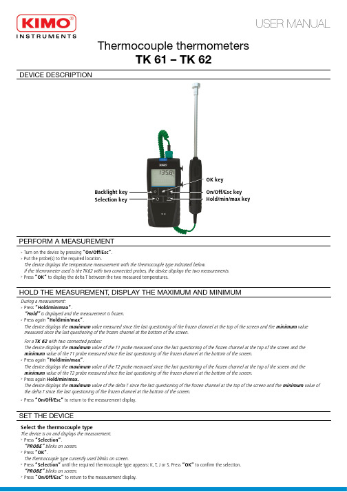
Thermocouple thermometersTK 61 – TK 62DEVICE DESCRIPTIONOK keyHold/min/max keySelection keyBacklight key On/Off/Esc key USER MANUAL➢Turn on the device by pressing “On/Off/Esc”.➢Put the probe(s) to the required location.The device displays the temperature measurement with the thermocouple type indicated below.If the thermometer used is the TK62 with two connected probes, the device displays the two measurements.➢Press “OK“ to display the delta T between the two measured temperatures.PERFORM A MEASUREMENTDuring a measurement:➢Press ”Hold/min/max”.“Hold” is displayed and the measurement is frozen.➢Press again “Hold/min/max”.The device displays the maximum value measured since the last questioning of the frozen channel at the top of the screen and the minimum value measured since the last questioning of the frozen channel at the bottom of the screen.For a TK 62 with two connected probes:The device displays the maximum value of the T1 probe measured since the last questioning of the frozen channel at the top of the screen and the minimum value of the T1 probe measured since the last questioning of the frozen channel at the bottom of the screen.➢Press again ”Hold/min/max”.The device displays the maximum value of the T2 probe measured since the last questioning of the frozen channel at the top of the screen and the minimum value of the T2 probe measured since the last questioning of the frozen channel at the bottom of the screen.➢Press again Hold/min/max.The device displays the maximum value of the delta T since the last questioning of the frozen channel at the top of the screen and the minimum value of the delta T since the last questioning of the frozen channel at the bottom of the screen.➢Press “On/Off/Esc” to return to the measurement display.HOLD THE MEASUREMENT, DISPLAY THE MAXIMUM AND MINIMUMSET THE DEVICESelect the thermocouple typeThe device is on and displays the measurement.➢Press ”Selection”.“PROBE” blinks on screen.➢Press “OK”.The thermocouple type currently used blinks on screen.➢Press “Selection” until the required thermocouple type appears: K, T, J or S. Press “OK” to confirm the selection.“PROBE” blinks on screen.➢Press ”On/Off/Esc” to return to the measurement display.N T a n g – T K 61-T K 62 – 01/06/17 – R C S (24) P ér i g u e u x 349 282 095 N o n -c o n t r a c t u a l d o c u m e n t – W e r e s e r v e t h e r i g h t t o m o d i f y t h e c h a r a c t e r i s t i c s o f o u r p r o d u c t s w i t h o u t p r i o r n o t i c e .The device is on.➢Press “Backlight” to activate the device backlight.➢Press again this key to deactivate the backlight.ACTIVATE THE BACKLIGHT➢Remove the front part at the back of the device.➢Change the old batteries by AAA LR03 1.5V batteries.➢Replace the frontREPLACE THE BATTERIESTo turn off the device:➢Carry out a long press on “On/Off/Esc”.TURN OFF THE DEVICESelect the temperature unitThe device is on and displays the measurement.➢Press “Selection” until “UNIT” blinks on screen. Press “OK”.The unit currently used blinks on screen.➢Press “Selection” until the required unit appears: °C or °F.➢Press “OK” to confirm the unit selection.“UNIT” blinks on screen.➢Press ”On/Off/Esc” to return to the measurement display.Activate or deactivate the keys beepThe device is on and displays the measurement.➢Press “Selection” until “BEEP” blinks on screen. Press “OK”.“OFF” or “ON” blinks on screen.➢Press “Selection” to activate the keys beep “ON” or deactivate it “OFF”.➢Press “OK” to confirm the selection.“BEEP” blinks on screen.➢Press ”On/Off/Esc” to return to the measurement display.Set the auto shut-offThe device is on and displays the measurement.➢Press “Selection” until “AUTO OFF” blinks on screen. Press “OK”.The time before the device auto shut-off blinks at the bottom of the screen.➢Press “Selection” until the required time before the device auto shut-off appears: 15, 30, 45, 60, 75, 90, 105, 120 minutes or OFF .➢Press “OK” to confirm the selection.“AUTO OFF” blinks on screen.➢Press ”On/Off/Esc” to return to the measurement display.Set the alarmThis function allows to activate a temperature alarm on channel 1 when the device reaches or exceeds a previously defined threshold. This threshold is between -200 and +1760°C according to the thermocouple type of the probe.The device is on and displays the measurement.➢Press “Selection” until “AL 1” blinks on screen.➢Press “OK”.The first digit blinks.➢Press “Selection” to select the value of the first digit according to the thermocouple type of the probe: -, 0, 1 or OFF .●If “Off” is selected, the alarm is deactivated. Press “OK” to confirm, “AL 1” blinks on screen.●If -, 0 or 1 is selected, press “OK”. The next digit blinks, press “Selection” to select its value then press “OK” to confirm. Perform the same procedure to select the value of the following digits (press “On/Off/Esc” to return to the previous digit). Press “OK” when the last digit is set, “AL 1” blinks on screen.➢Press ”On/Off/Esc” to return to the measurement display.Once returned to KIMO, required waste collection will be assured in the respect of the environment in accordance to 2002/96/CE guidelines relating to WEEESAFETY INSTRUCTIONSIn order to avoid any risk of a voltage on the surface of the element on which we want to perform a temperature measurement, the thermocouple(s) MUST NOT be under a voltage higher than 30 V alternating or 60 V direct voltage relating to earth.In order to avoid any damage on the device, the voltage between the two thermocouples MUST NOT be higher than 0.5 V.。
热电偶型温度计SS-CP-2280-US使用手册说明书

Specification Sheet SS-CP-2280-USFeaturesDesigned for people who perform tests and verifications of temperature sensing devices in the field. This instrument is ideal when time is a criti-cal factor and the highest accuracy is not a critical factor.Reduced size and weight are important considerations because the unit is able to fit into a tool box or instrument carrying case and can be used for sensors that are difficult to access.One-key-one-function user interface provides immediate access to set-ting the temperature and the auto-step timesaving function. There is no need for manipulation of sophisticated menus.The Stability indicator provides audible and visual prompts when the temperature is stable. This function also includes a 3 minute countdown before the stable condition.Stainless steel and rubber side panels make the instrument suitable for many years of faithful duty in an industrial environment.PRODUCT DESCRIPTIONHeats up by up to 100°C / 212°F per minute and completes a full dual-point test in less than 10 min-utes, including stability time; timesavings at your fingertips! The ETC- series is designed for field testing of temperature measure-ment devices.The small size and light weight make it a perfect instrument to verify sensors in difficult to reach places.All JOFRA ETC units have many of the same useful and timesaving features offered in the more advanced JOFRA dry-block series.Model ETC-seriesEasy Temperature CalibratorETC-400 R for infrared thermometersThe ETC-400 R is designed for optimum speed in connec-tion with calibration of infrared thermometers. The 36 mm target provides the optimum size for reliable calibrationof infrared thermometers in the process industry as it is designed for high accuracy and long-term stability while maintaining speed.With regard to the coating of the target it has been espe-cially designed for space technology applications, which secure long time performance under high temperature influence. In combination with the shape of the target it ensures the emissivity of 0.96.If higher accuracy is required, and for recalibration, a 3 mm external JOFRA STS reference probe can be placed under the surface of the target.Find ordering information for the STS-103 B reference sensor at page 7.Super fast heating - ETC-400 A dry-blockThe ETC-400 A is designed for optimum speed. The heat-ing block is built around a highly efficient heating element. The insertion holes for the temperature device undertest are located around this element. To reduce mass and increase effectiveness, there is no removable inser-tion tube; the holes are drilled directly into the block. The minimal mass offers an extremely fast heating and cooling time. The different layouts also make it possible to use an external JOFRA STS reference probe during the calibra-tion. Choose the combination of holes that best suits your needs from our various design combinations.If your application requires a dry-block that can handle large sensors or more than one sensor at a time, we offer several other JOFRA dry-block calibrators that can meet your needs.Cooling and heating - ETC-125 A dry-blockThe ETC-125 A is a simple yet effective tool for verify-ing temperature instruments that also require references below ambient temperatures: e.g. air-conditioning and cold counters. The predrilled holes allow the use of an insertion tube in the largest bore. This increases the flex-ibility to match many sensor-under-test sizes.Easy-to-use, intuitive operationAll instrument controls are accessed directly from the front panel. The main functions on the ETC series are designed with one-key-one-function logic. This means that there are no difficult multiple keystrokes to remember to access pri-mary functions. The easy-to-read, backlit display features dedicated icons, which help in identifying instrument con-ditions and operational steps.Set temperatureThe ’’Up’’ and ’’Down’’ arrow keys allow the user to set the exact temperature desired with a resolution of 0.1°C or °F.Instrument setupsThe ETC-series stores the complete instrument setup, including: engineering units, stability criteria, resolution, auto-step settings, and maximum temperature.Stability indicatorThe bold checkmark on the display indicates that the calibrator has reached the desired set temperature and is stable. The operator may change the stability criteria and establish a greater level of confidence in the calibration results as desired. A convenient countdown timer is acti-vated three minutes before the unit reaches stability. Thisprompts you to be prepared to record results.2 JOFRA IR-LAB software for the ETC-400 RAs an extra feature the ETC-400 R will be delivered with a small mathematical program, which will constitute a powerful tool together with the calibrator. The program enables you to calculate at which temperatures you need to calibrate, if your IR thermometer is either locked to a fixed emission factor or if you just want to calibrate your thermometer at a certain emission factor. The program fa-cilitates the whole issue of correcting settings of emission factors and temperatures.The calibration surface of the JOFRA ETC-400 R IR calibrator has an emission factor of 0,96. If your IR-ther-mometer is using a different emission factor than 0.96, the result will be a faulty temperature reading on your IR thermometer. However if your IR thermometer is using an emission factor of 0.95 or 0.98 – a helpfull diagram is part of the standard delivery.Example: Your thermometer is locked to an emission factor of 0,98 and you have set the JOFRA ETC-400 R to 300°C. The diagram indicates that 3,9°C must be subtracted from the calibrator temperature, to obtain the “true” IR thermometer reading (296,1°C).If you are working with IR thermometers where the emis-sion factor is different than 0.95, 0.96 or 0.98, or other parameters differ from “standard”, use the PC program JOFRA IR-Lab. The JOFRA IR-Lab program allows you to type in various emission factors, in order to get a “true” temperature readout on your thermometer or the other way around - what is the true surface temperature of the calibrator. But the IR-Lab will do more than that; it allows you to calculate “true” temperatures in simulated sur-roundings that approximate your actual test environments.Calibration of up to 24 sensors with JOFRA ASMUsing the JOFRA ETC series together with the ASMAdvanced Signal Multi-scanner offers a great time-saving automatic solution to calibrate multiple temperature sen-sors at the same time.The ASM series is an eight channel scanner controlled by JOFRACAL software on a PC. Up to 3 ASM units can be stacked to calibrate up to 24 sensors at the same time. It can handle signals from 2-, 3- and 4 wire RTD’s, TC’s, transmitters, thermisters, temperature switches and volt-age.Please also see more in specification sheet SS-CP-2360, which can be found at www.jofra.comAuto-steppingThis feature saves time. The operator may stay in the con-trol room, or another remote location, monitoring the out-put from the sensor-under-test while the ETC- series cali-brator is placed in the process and automatically changes the temperature using a programmed step value and rate. Up to 9 different temperature steps may be programmed, including the hold time for each step. This feature is also ideal for burning-in new sensors prior to installation; this minimizes initial drift and allows for initial testing. It is also useful for testing temperature data loggers.Maximum temperatureFrom the setup menu, you can select a lower maximum tem-perature limit for the calibrator. This function prevents damage to the sensor-under-test caused by the application of exces-sive temperatures.Re-calibration/adjustments made easyThe ETC- series has a very easy and straightforward pro-cedure for re-calibration/adjustment. There is no need for a screwdriver or PC software. The only thing you need is a reliable reference thermometer. Place the probe in thecalibrator and follow the instructions on the display.Use the ETC calibrator with JOFRACAL calibration software 3122832 Cleaning Brushes - 4 mm - Package of 3 pcs 60F174 Cleaning Brushes - 6 mm - Package of 3 pcs 122822 Cleaning Brushes - 8 mm - Package of 3 pcs 125002 Edgeport Converter with 4 pcs of RS232 ports 124094Carrying Case for ETC Series1) The ETC-400 R is delivered with a carrying case as standard because it is important to keep dust away from the surface of the target on the ETC-400 R. The reason being that a clean surface is important to keep the emissivity and thereby the accuracy. The car-rying case is optional for ETC-400 A and ETC-125 A.STANDARD DELIVERYJOFRA ETC dry-block calibratorTraceable calibration certificate - temperatureperformanceJOFRACAL calibration software User and reference manual Mains power cable Shoulder strap RS232 cable1 × predrilled insertion tube (ETC-125 A only)Tool for insertion tubes (ETC-125 A only)Carrying case (ETC-400 R only) 1)JOFRA IR-LAB calibration software (ETC-400 R only)Emissivity table (ETC-400 R only)••••••••••••ACCESSORIESCarrying case (Optional for ETC-125 / 400 A) - 124094The optional protective carrying case ensures safe trans-portation and storage of the instrument and all associated equipment.JOFRACAL CALIBRATION SOFTWAREJOFRACAL calibration software ensures easy calibration of RTD´s, thermocouples, transmitters, thermoswithes, pressure gauges and pressure switches. JOFRACAL can be used with JOFRA DPC-500, APC, CPC and IPI pres-sure calibrators, all JOFRA temperature calibrators, as well as JOFRA AMC900, ASC300 multi signal calibrator and ASM-800 signal multi scanner.JOFRACAL calibration software may also be used for manual calibrations, as it can be set up to accept manual entry of calibration data together with other liquid baths, ice points or dry-block heat sources.The calibration data collected may be stored on a PC for later recall or analysis. The calibrator stores the calibration procedure and may be taken out to the process site with-out using a personal computer.Once all calibrations are completed, the data may be uploaded to the JOFRACAL calibration software for post-processing and printing of certificates. The calibration data collected may be stored on the personal computer for later recall or analysis.The JOFRACAL temperature calibration software may bedonwloaded from our web-page .Please also see more about JOFRACAL calibration software in specification sheet SS-CP-2510, which can be found atJOFRACAL softwareMinimum hardware requirements for JOFRACAL calibra-tion software.INTEL TM 486 processor(PENTIUM TM 800 MHz recommended)32 MB RAM (64 MB recommended)80 MB free disk space on hard disk prior to installation Standard VGA (800 x 600, 16 colors) compatible screen (1024 x 786, 256 colors recommended)CD-ROM drive for installation of the program 1 free RS232 serial port••••••••4 *******************************°C/73°F ETC-125 A Maximum ........................................................125°C / 257°F *********************°C/32°F...........-18°C / -0°F **********************°C/73°F............-10°C/14°F **********************°C/104°F...........6°C / 43°F ETC-400 A ......................28 to 400°C / 82 to 752°F@ 23°C ETC-400 R ......................28 to 400°C / 82 to 752°F@ 23°C Resolution (user-selectable)Selectable .............................................................1º or 0.1ºHeating timeETC-125 A-10 to 23°C / 14 to 73°F .........................................3 minutes 23 to 100°C / 73 to 212°F ....................................11 minutes 100 to 125°C / 212 to 257°F ..................................7 minutes ETC-400 A / R28 to 200°C / 82 to 392°F .....................................2 minutes 200 to 400°C / 392 to 752°F .................................3 minutes Cooling timeETC-125 A125 to 100°C / 257 to 212°F .................................1 minute 100 to 0°C / 212 to 32°F ......................................17 minutes 0 to -10°C / 32 to 14°F .........................................14 minutes ETC-400 A400 to 200°C / 752 to 392°F .................................6 minutes 200 to 50°C / 392 to 122°F ..................................15 minutes ETC-400 R400 to 200°C / 752 to 392°F .................................9 minutes 200 to 50°C / 392 to 122°F ..................................24 minutes StabilityETC-125 A ..............................................±0.05°C / +0.09°F ETC-400 A .............................................±0.15°C / +0.27°F ETC-400 R ...............................................±0.3°C / ±0.54°FMeasured after the stability indicator has been on for 10 minutes. Measuring time is 30 minutes.Time to stability (approximate)All models .............................................................3 minutes AccuracyETC-125 A ...............................................+0.5°C / +0.9°F 1)ETC-400 A ..............................................+0.5°C / +0.9°F 1) ETC-400 R ..............................................±0.5°C / ±0.9°F 2) ETC-400 R incl. emissivity....................................±0.4% rdg ±1°C / ±0.4% rdg. ±1.8°F1) Specification when using the internal reference. (Load 4 mm OD reference probe in the center of the insert).2) Specification when using the internal reference. (Load 3 mmOD reference probe).FUNCTIONAL SPECIFICATIONSImmersion depthETC-125 A (insulation included) ................. 110 mm / 4.3 in ETC-400 A ...................................................105 mm / 4.1 in Mains specificationsVoltage ETC-125 A .........Multivoltage 115VAC and 230VAC ........................................115V(90-132) and 230V(180-264)Voltage ETC-400 A/R .......115V(90-127) or 230V(180-254)Frequency ETC-125 A ..........................................47 - 63 Hz Frequency ETC-400 A/R .....................................45 - 65 Hz Power consumption (max.) ETC-125 A .......................75 VA Power consumption (max.) ETC-400 A/R .................350 WKEY FEATURESAuto steppingProgrammable .................................................Up to 9 steps Dwell time on each step ...............................Programmable Multi-information displayStability indicator .......................................Clear checkmark Countdown timer before stable .............................3 minutes Temperature .......................SET and READ simultaneously Alphanumeric messages ................................................Yes Calibration status icons ..................................................Yes Training mode (heating/cooling block disabled)Simulation of all functions ..............................................Yes Simulating heating and cooling .....Approx. 100° per minute Service facilitiesAdjustment of the unit from the keypad .........................Yes Self explaining guide in display......................................... Y es Other information: ............................Display serial number, ..................software revision level, and last calibration date Setup facilitiesStability criteria: .........Extra time before ’’stable indication’’ ................................................................................is shown Display resolution ..............................................1° or 1°C/°F Temperature units ...................................................°C or °F Slope rate .................................................0.1 to 9.9°/minute Maximum temperature.....................Any value within range 5INSERTS FOR ETC SERIESMetric Multi-hole Type 21(ETC-400 A)Type 51 ETC-400 R36 mm (1.4 in) targetImperial Type 02 (ETC-125 A)Metric Type 01 (ETC-125 A)Imperial Multi-hole Type 12(ETC-400 A)Imperial Multi-hole Type 11(ETC-400 A)PHYSICAL SPECIFICATIONSInstrument dimensionsETC-125 A, ETC-400 A and ETC-400 RL × W × H: ................172 × 72 × 182 mm / 6.8 × 2.8 × 7.2 in Instrument weightETC-125 A .......................................................1.8 kg / 3.9 lb ETC-400 A ......................................................1.6 kg / 3.5 lb ETC-400 R ......................................................1.7 kg / 3.7 lb Shipping (including shipping cargo box)ETC-125 A: ......................................................3.0 kg / 6.6 lb ETC-400 A: ....................................................2.8 kg / 6.2 lb ETC-400 R ......................................................4.5 kg / 9.9 lb Size, L × W × H:ETC-125 A / 400 A: .............................................................. .............................345 × 235 × 135 mm / 13.6 × 9.3 × 5.3 in ETC-400 R .........425 x 320 x 165 mm / 16.7 x 12.5 x 6.5 in MiscellaneousSerial data interface .................................................RS232Operating temperature .....................0 to 40°C / 32 to 104°F Storage temperature ......................-20 to 50o C / -4 to 122o F Humidity ..........................................................0 to 90% RH Protection class ...........................................................IP-10DNV Marine Approval, Certificate no ......................A-103846 STS103B150AH Sample order numberReference Pt100 150 mm., cable length 0.5 m (1.6 ft.) with LEMO termination and accredited certificateIt is not easy to make a good quality reference probe. The main requirement of a reference probe is stability. This means minimal drift as a function of operating time at the actual temperature. The less the probe drifts, the lower the measurement uncertainty.Especially for the ETC-400 R calibrator JOFRA hasdesigned a special 3 mm STS reference sensor, the STS-103 B. The sensor can be used as a reference sensor when a higher accuracy is required or for recalibration of the ETC-400 R. Due to the small immersion depth require-ment of the sensor it can be placed under the surface of the target.Temperature rangeAll probes ..................................-50 to 400°C / -58 to 752°F AccuracyHysteresis 1) @0°C / 32°F ..............................0.01°C / 0.02°F Long term stability 2) @0°C / 32°F .....typ. 0.014°C / 0.025°F Repeatability 1) ........................................0.005°C / 0.009°FNote 1: When used in the range -45 to 400°C / -49 to 752°F. Note 2: When exposed to 400°C / 752°F for 100 h. Stability will depend on actual use of the sensor.Sensing elementType .............................................................................Pt100Nominal resistance@0°C / 32°F .................................100 ΩLength ............................................................6 mm / 0.2 in Temperature coefficient .........................α100=0.00385 1/°C Minimum immersion depthSTS-103 B (3 mm / 0.12 in): ..........................40 mm / 1.6 in Self-heating effect 0.06°C/mW / 0.108°F/mW Response timeτ0.5 (50%) ..............................................................5 seconds τ0.9 (90%) ............................................................15 secondsLiquid in motion v=0.4m/s.Electrical connectionsCable .............................................................4 wire + shield Connection ...............................................LEMO goldplated Insulation resistance@ 23°C / 73°F .....................................................100 Gohm @ 400°C / 752°F ...................................................70 Mohm Outer tube Inconel 600Operating conditions(Probe, connection, and cable) ..............Max. 70°C / 158°F Storage temperature ....................-20 to 70o C / -4 to 158o F Humidity ..........................................................0 to 90% RH Protection class (connectors) ...................DIN 40050 IP-50Shipping dimensions - including carrying case L x W x H ..............750 x 140 x 140 mm / 29.5 x 5.5 x 5.5 in Shipping weight including packingSTS-103 B ..........................................................2 kg / 4.4 lbSPECIFICATIONS STS-103 BJOFRA STS-103 B probeCable - according to order number Accredited certificate, points: -45, -20, 0, 50, 100, 200, 400°C Plastic carrying case with foam insert User manual•••••STANDARD DELIVERYDimensionsRef.mm inch A 150 5.91B30.12JOFRA STS-103 B 7Order no. DescriptionBase model numberETC125A ETC-125 A, -10 to 125°C / 14 to 257°F ETC400A ETC-400 A, 28 to 400°C / 82 to 752°F ETC400RETC-400 R, 28 to 400°C / 82 to 752°CPower supply115 ETC-400 A/R only: 115 VAC, 50/60 Hz 230 ETC-400 A/R only: 230 VAC, 50/60 HzMUL ETC-125 A only: Multi voltage 115 and 230 VAC Mains power cable type A European, 230 V, B USA/Canada, 115 V C UK, 240 VD South Africa, 220 VE Italy, 220 VF Australia, 240 VG Denmark, 230 VH Switzerland, 220 V IIsrael, 230 VHoles for sensor-under-test01 ETC125 A - Metric (12.5 mm, 6 mm, 4 mm, 8 mm) 02 ETC125 A - Imperial (1/2 in, 3/8 in, 1/4 in, 5/32 in) 11 ETC400 A - Imperial (1/16 in, 1/8 in, 5/32 in, 3/16 in, 1/4 in) 12 ETC400 A - Imperial (1/16, 1/8 in, 3/16 in, 1/4 in, 3/8 in) 21 ETC400 A - Metric (2 mm, 3 mm, 4 mm, 6 mm) 51 ETC400 RCalibration certificateE NPL and NIST traceable calibration certificate (standard delivery)H Accredited calibration certificate(on quotation basis)OptionsC Carrying case (standard for ETC-400 R)ETC400A230A21EC Sample order numberJOFRA ETC-400 A series dry-block, 230 VAC power, European power cord, metric drilled multihole block, standard NPL/NIST traceable certifi-cate and carrying case.ORDERING INFORMATIONPub code SS-CP-2280-US Issue 09018 Sales & Service Offices:AMETEK Mansfield & Green (North America)Tel:+18005279999•*******************AMETEK Singapore Pte. Ltd. (Singapore)Tel:+6564842388•***************.sg AMETEK Inc. Beijing Rep. Office (China)Tel:+861085262111•****************.cn AMETEK GmbH (Germany)Tel:+4921599136510•*********************AMETEK Calibration Instruments (UK)Tel:+44(0)1489486404•***************.ukHeadquarters:AMETEK Denmark A/SGydevang 32-34 • 3450 Allerød • Denmark Tel:+4548168000•****************Sales & Service:Europe, Asia, Africa, Middle East and South AmericaInformation in this document is subject to change without notice. ©2007, by AMETEK, Inc., . All rights reserved.AMETEK Calibration Instrumentsis one of the world’s leading manufacturers anddevelopers of calibration instruments for temperature, pressure and process signals as well as for temperature sensors both from a commercial and a technological point of view. JOFRA Temperature InstrumentsPortable precision thermometers. Dry-block and liquid bath calibrators: 4 series, with more than25 models and temperature ranges from-90° to 1205°C / -130° to 2200°F. All featuring speed,portability, accuracy and advanced documenting functions with JOFRACAL calibration software.JOFRA Pressure InstrumentsConvenient electronic systems ranging from-1 to 1000 bar (25 inHg to 14,500 psi) -multiple choices of pressure ranges, pumps andaccuracies, fully temperature-compensatedfor problem-free and accurate field use. JOFRA Signal InstrumentsProcess signal measurement and simulation for easy control loop calibration and measurementtasks - from handheld field instruments tolaboratory reference level bench top instruments.JOFRA / JF Marine InstrumentsA complete range of calibration equipmentfor temperature, pressure and signal,approved for marine use.FP Temperature SensorsA complete range of temperature sensorsfor industrial and marine use.M&G Pressure TestersPneumatic floating-ball or hydraulic piston dead weight testers with accuracies to 0.015% of reading.M&G PumpsPressure generators from small pneumatic “bicycle” style pumps to hydraulic pumps generating up to 1,000 bar (15,000 psi)....because calibration is a matter of confidence。
英文安装说明书[1]
![英文安装说明书[1]](https://img.taocdn.com/s3/m/cb8afdda240c844769eaeefc.png)
2.4The mutual inductor secondary lines draw out with the4m㎡polyvinyl-chloride baling wire ,Is convenient for the wiring, gets "S1" on the wiring ear, "S2", "S3" and so on the mark..
2.5The entire mutual inductor soaks the insulating paint after the seasoning, after but dries, by guards against is affected with damp.
3.Techical Date
2.3On the post mutual inductor has the data plate and the polar symbol sign,symbolized on the sign the sign has "on" the inscription."On" indicated primary current in the mutual inductor the direction,Namely the expression works as when primary current by "on" end inflow, the secondary current then flows out from the S1 end after exterior load return route flows in the S2 end (or S3, S4, S5 end) .
热电偶温度计 911B, 912B 操作手册 - 中文简体版说明书

热电偶温度计型号:911B, 912B 热电偶温度计操作手册rev B手册零件编号:911B-900, Rev. B2018 年 1 月出版,Geneva, OH注意事项版权声明© TEGAM, Inc., 2018依据美国和国际版权法规定,事先未取得TEGAM, Inc 的书面同意,禁止以任何形式或方式对本手册的内容进行复制(包括电子存储和检索或翻译为其他语言)。
本手册零件编号:911B-900修订版 B,2018 年 1 月取代:修订版 A,2017 年 11 月出版者:TEGAM, Inc.10 TEGAM WayGeneva, OH 44041免责说明和手册修订:本用户手册中包含的材料,以及与本手册相关的所有计算机软件或涉及的产品均以现况提供,如在以后的修订版中做出变更,恕不另行通知。
本用户手册在出版时为最新版本。
不过TEGAM 致力于持续不断地对产品做出改进,因此本手册中所涵盖的产品和所有相关的计算机软件都可能会定期在功能和设计上进行更新。
如需最新的产品文件,请访问 。
美国政府权利计算机软件和/或技术数据是自费开发的专有资料。
授予联邦政府的计算机软件和技术数据权利仅包括通常给予公众的权利,并遵循联邦政府FAR 12.211 (技术数据)和FAR 12.212(计算机软件)以及国防部的DFARS 252.227-7015 (技术数据-商业制品)和DFARS 227-7202-3 (商业计算机软件或计算机软件文档中的权利)。
除上述明确许可外,禁止复制计算机软件和技术数据中的信息或插图用于非政府性用途。
兼容性安全注意事项符号和术语安全注意事项代表着危险。
其表示如错误执行或遵守操作程序、说明或实践,可导致设备损坏、人员受伤或死亡。
在未充分理解和遵守所有条件和说明前,请勿超出安全注意事项的要求执行操作。
安全注意事项符号:警告警告代表迫近的危险,可能导致人员受伤或死亡。
小心注意代表可能导致装置或其他设备损坏的危险。
热电偶安装手册(中英文)

热电偶安装手册(中英文)WR系列热电偶WR Series ThermocoupleWZ系列热电阻WR Series Thermocouple使用安装手册Installation & Operation Manual安徽天康(集团)股份有限公司Anhui Tiankang (Group) Shares Co., Ltd目录Index1、概述General Description (1)2、工作原理Operation Theory (1)3、结构Configuration (2)4、主要技术参数Main Technical Parameters (3)5、安装及使用Installation & Operation (5)6、可能发生的故障及维修Possible Troubles & Maintenance (7)7、运输及储存Transportation & Storage (8)8、订货须知Notices in Ordering (8)9、型号命名Type Naming (9)1、概述General Description工业用热电偶作为温度测量和调节的传感器,通常与显示仪表等配套,以直接测量各种生产过程中-40~1600℃液体、蒸汽和气体介质以及固体表面温度;As sensor for temperature measuring and regulation, industrial-purpose thermocouple is usually connected with display meter and other meters to directly measure temperature of liquid, vapor, gas and solid surface ranging from -40℃to 1600℃.工业用热电阻作为温度测量和调节的传感器,通常与显示仪表等配套,以直接测量各种生产过程中-200~500℃液体、蒸汽和气体介质以及固体表面温度。
SMT中英文对照
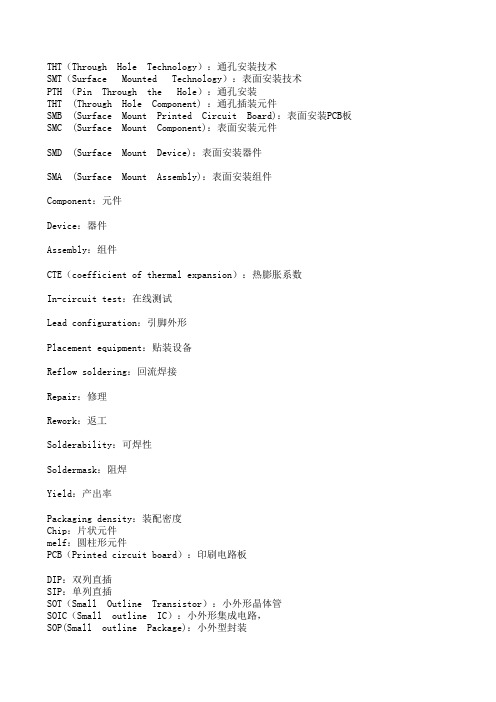
THT(Through Hole Technology):通孔安装技术SMT(Surface Mounted Technology):表面安装技术PTH (Pin Through the Hole):通孔安装THT (Through Hole Component) :通孔插装元件SMB (Surface Mount Printed Circuit Board):表面安装PCB板SMC (Surface Mount Component):表面安装元件SMD (Surface Mount Device):表面安装器件SMA (Surface Mount Assembly):表面安装组件Component:元件Device:器件Assembly:组件CTE(coefficient of thermal expansion):热膨胀系数In-circuit test:在线测试Lead configuration:引脚外形Placement equipment:贴装设备Reflow soldering:回流焊接Repair:修理Rework:返工Solderability:可焊性Soldermask:阻焊Yield:产出率Packaging density:装配密度Chip:片状元件melf:圆柱形元件PCB(Printed circuit board):印刷电路板DIP:双列直插SIP:单列直插SOT(Small Outline Transistor):小外形晶体管SOIC(Small outline IC):小外形集成电路,SOP(Small outline Package):小外型封装PLCC(Plastic Leaded Chip Carrier):塑型有引脚芯片载体LCCC(Leadless Ceramic Chip Carrier):无引脚陶瓷芯片载体QFP(Quad Flat Package):多引脚方形扁平封装BGA( Ball grid array)球栅列阵CSP(Chip Scale Package):芯片规模的封装Bare Chip:裸芯片Accuracy:精度ATE(Automated test equipment):自动测试设备AOI(Automatic optical inspection):自动光学检查Blind via:盲孔Buried via:埋孔through via:通孔Bridge:锡桥Circuit tester:电路测试机CTE(Coefficient of the thermal expansion):温度膨胀系数Cold solder joint:冷焊锡点Component density:元件密度Copper foil:铜箔Copper mirror test:铜镜测试Cure:烘焙固化Cycle rate:循环速率Defect:缺陷Desoldering:卸焊Downtime:停机时间FPT(Fine-pitch technology):密脚距技术Flip chip:倒装芯片FCT(Functional test):功能测试Golden boy:金样ICT(In-circuit test):在线测试JIT(Just-in-time):刚好准时Lead configuration:引脚外形Packaging density:装配密度Pick-and-place:拾取-贴装设备Placement equipment:贴装设备Reflow soldering:回流焊接Repair:修理Rework:返工Defect SoldeR少锡Schematic:原理图Solder bump:焊锡球Solderability:可焊性Soldermask:阻焊Tape-and-reel:带和盘Tombstoning:元件立起Ultra-fine-pitch:超密脚距Yield:产出率solder mask:阻焊漆silk screen:丝印面via:导孔Copper Clad Laminates:覆铜箔层压板past mask:焊膏膜(漏板)solder mask:焊接掩摸(阻焊膜)Solding Pasts:焊锡膏Stencils:模板、漏板、钢板Bridging:搭锡Cursting:发生皮层Excessive Paste:膏量太多Insufficient Paste:膏量不足Poor Tack Retention:粘着力不足Slumping:坍塌Smearing:模糊Dpm(defects per million):百万缺陷率Flexibility:柔性Modularity:模块化Component Pick-Up:元件拾取Component Check:元件检查Component Transport:元件传送Placement Procedure:元件放置Chamber System:炉膛系统Blowholes:吹孔Voids:空洞Movement:移位Misalignment:偏斜Dewetting:缩锡Dull Joint:焊点灰暗Non-Dewetting:不沾锡Accuracy:精度Additive Process:加成工艺Adhesion:附着力Aerosol:气溶剂Angle of attack:迎角Anisotropic adhesive:各异向性胶Annular ring:环状圈Application specific integrated circuit :ASIC特殊应用集成电路Array:列阵Artwork:布线图Automated test equipment:ATE自动测试设备Bond lift-off:焊接升离Bonding agent:粘合剂CAD/CAM system:计算机辅助设计与制造系统Capillary action:毛细管作用Chip on board :COB板面芯片Circuit tester:电路测试机Cladding:覆盖层Cold cleaning:冷清洗Cold solder joint:冷焊锡点Conductive epoxy:导电性环氧树脂Conductive ink:导电墨水Conformal coating:共形涂层Copper foil:铜箔Copper mirror test:铜镜测试Cure:烘焙固化nought materiel 无料Cycle rate:循环速率Data recorder:数据记录器Defect:缺陷Delamination:分层Desoldering:卸焊Dewetting:去湿DFM:为制造着想的设计Dispersant:分散剂Documentation:文件编制Downtime:停机时间Durometer:硬度计Environmental test:环境测试Eutectic solders:共晶焊锡Fiducial:基准点Fillet:焊角Fine-pitch technology :FPT密脚距技术Fixture:夹具Full liquidus temperature:完全液化温度Golden boy:金样Halides:卤化物Hard water:硬水Hardener:硬化剂Line certification:生产线确认Machine vision:机器视觉Mean time between failure :MTBF平均故障间隔时间Nonwetting:不熔湿的Organic activated :OA有机活性的Packaging density:装配密度Photoploter:相片绘图仪Placement equipment:贴装设备Repeatability:可重复性Rheology:流变学Schematic:原理图Semi-aqueous cleaning:不完全水清洗Shadowing:阴影Silver chromate test:铬酸银测试Slump:坍落Solder bump:焊锡球Solderability:可焊性Soldermask:阻焊Solids:固体Solidus:固相线Statistical process control :SPC统计过程控制Storage life:储存寿命Subtractive process:负过程Surfactant:表面活性剂Syringe:注射器Tape-and-reel:带和盘Thermocouple:热电偶Tombstoning:元件立起Vapor degreaser:汽相去油器paste working 1ife:焊膏工作寿命paste shelf life:焊膏贮存寿命slump:塌落no-clean solder paste:免清洗焊膏low temperature paste:低温焊膏screen printing:丝网印刷screen printing plate:网版squeegee:刮板screen printer:丝网印刷机stencil printing:漏版印刷metal stencil:金属漏版flexible stencil:柔性金属漏版feeders:供料器tape feeder:带式供料器stick feeder:杆式供料器tray feeder:盘式供料器bulk feeder:散装式供料器feeder holder:供料器架placement accuracy:贴装精度shifting deviation:平移偏差rotating deviation:旋转偏差resolution:分辨率repeatability:重复性placement speed:贴装速度low speed placement equipment:低速贴装机general placement equipment:中速贴装机high speed placement equipment:高速贴装机precise placement equipment:精密贴装机optic correction system :光学校准系统sequential placement:顺序贴装placement pressure:贴装压力placement direction:贴装方位flying:飞片flux bubbles:焊剂气泡dual wave soldering:双波峰焊self alignment:自定位skewing:偏移tomb stone effect:墓碑现象Manhattan effect:曼哈顿现象hot air reflow soldering:热风再流焊convection reflow soldering:热对流再流焊laser reflow soldering:激光再流焊vapor phase soldering(VPS): 气相再流焊located soldering:局部软钎焊cleaning after soldering:焊后清洗AI :Auto-Insertion 自動插件AQL :acceptable quality level 允收水準ATE :automatic test equipment 自動測試ATM :atmosphere 氣壓BGA :ball grid array 球形矩陣CCD :charge coupled device 監視連接元件(攝影機) CLCC :Ceramic leadless chip carrier 陶瓷引腳載具COB :chip-on-board 晶片直接貼附在電路板上cps :centipoises(黏度單位) 百分之一CSB :chip scale ball grid array 晶片尺寸BGACSP :chip scale package 晶片尺寸構裝CTE :coefficient of thermal expansion 熱膨脹系數DIP :dual in-line package 雙內線包裝(泛指手插元件)FPT :fine pitch technology 微間距技術FR-4 :flame-retardant substrate 玻璃纖維膠片(用來製作PCB材質)IC :integrate circuit 積體電路IR :infra-red 紅外線Kpa :kilopascals(壓力單位)LCC :leadless chip carrier 引腳式晶片承載器MCM :multi-chip module 多層晶片模組MELF :metal electrode face 二極體MQFP :metalized QFP 金屬四方扁平封裝NEPCON :National Electronic Package andProduction Conference 國際電子包裝及生產會議PBGA:plastic ball grid array 塑膠球形矩陣PCB:printed circuit board 印刷電路板PFC :polymer flip chipPLCC:plastic leadless chip carrier 塑膠式有引腳晶片承載器Polyurethane 聚亞胺酯(刮刀材質)ppm:parts per million 指每百萬PAD(點)有多少個不良PAD(點)psi :pounds/inch2 磅/英吋2PWB :printed wiring board 電路板QFP :quad flat package 四邊平坦封裝SIP :single in-line packageSIR :surface insulation resistance 絕緣阻抗SMC :Surface Mount Component 表面黏著元件SMD :Surface Mount Device 表面黏著元件SMEMA :Surface Mount EquipmentManufacturers Association 表面黏著設備製造協會SMT :surface mount technology 表面黏著技術SOIC :small outline integrated circuitSOJ :small out-line j-leaded packageSOP :small out-line package 小外型封裝SOT :small outline transistor 電晶體SPC :statistical process control 統計過程控制SSOP :shrink small outline package 收縮型小外形封裝TAB :tape automaticed bonding 帶狀自動結合TCE :thermal coefficient of expansion 膨脹(因熱)係數Tg :glass transition temperature 玻璃轉換溫度THD :Through hole device 須穿過洞之元件(貫穿孔)TQFP :tape quad flat package 帶狀四方平坦封裝UV :ultraviolet 紫外線uBGA :micro BGA 微小球型矩陣cBGA :ceramic BGA 陶瓷球型矩陣PTH :Plated Thru Hole 導通孔IA Information Appliance 資訊家電產品MESH 網目OXIDE 氧化物FLUX 助焊劑LGA (Land Grid Arry)封裝技術 LGA封裝不需植球,適合輕薄短小產品應用。
Eurofase 加热电气控制箱安装手册说明书

PLEASE SAVE THIS MANUAL FOR FUTURE REFERENCE.READ THIS MANUAL CAREFULLY .SEE INSIDE COVER FOR IMPORTANT INFORMATION ABOUT THIS MANUAL.KEEP INSTRUCTION WITH APPLIANCE FOR FUTURE REFERENCE.Version 20230719OUTDOOR RATEDPLEASE READ ALL INSTRUCTIONS PRIOR TO INSTALLING THE EUROFASE HEATING ELECTRICAL CONTROL BOX.This manual contains important information about the installation, and operation of the Eurofase Heating Electrical Control Box. Please pay close attention to the important safety information shown throughout this instruction manual.A LICENSED ELECTRICIAN IS REQUIRED TO INSTALL THIS PRODUCT.Note: Eurofase Heating reserves the right to make changes to specifications, parts, components and equipment without prior notification.This Installation, operation and service manual may not be reproduced in any form with prior written consent from Eurofase Heating.Head Office:33 West Beaver Creek Road, Richmond Hill, ON L4B 1L8 CanadaTel: Contents WARNINGS............................................................................................Page 2 & 4PRODUCT OVERVIEW............................................................................Page 5INSTALLATION / SAFETY INFORMATION..............................................Page 5WIRING DIAGRAMS...............................................................................Page 6-12PRODUCT: Eurofase Heating Electrical Control BoxThe Eurofase Heating Electrical Control Box makes managing your comfort zone easier. It helps control multiple heaters and furthermore, creates varied heat zones throughout your space. Optimizing the warmth based on your preference or your guests’ requirements becomes a tailor-made experience. For full coordination and a seamless application to your home or commercial space, the Eurofase Heating Electrical Control Box is compatible with any 0-10V , 120-277V lighting dimmer. This Eurofase Heating Electrical Control Box is a highly recommended addition for commercial spaces like restaurant patios where customers have individual heat preferences. Modify each area with precise temperature conditions that are easily accessible and achievable with this Eurofase Heating Electrical Control Box that is ETL listed and Made in Canada.PRODUCT FEATURES:• This Eurofase Heating Electrical Control Box is suitable for 0-10V Dimmer , where the grey wire is common (0V) and purple wire is positive (10 VDC).• One dimmer controls up to 12,000W at the applicable rated voltage.• Dimming capability: 0% to 100%• Eurofase Heating Electrical Control Box can control heaters with voltages ranging from 240V max or 480V max at the rated amperage.INSTALLATION:Study the Installation Instructions at the end of this document before starting installation.1. Open cover of box.2. Follow pages 6 to 9 to wire in power and heaters per the instruction manual drawings.3. Follow page 10 to 12 to wire in dimmers and timers as per the installation manual drawings.4. Refit cover to the box.OPERATION:Responsibility for determining suitability for use in any application / equipment lies solely on the purchaser.Suitability for use in your application is determined by applicable standards such as UL and cUL and the completed system involving this component should be tested to those standards. Please consult with local authorities and applicable wiring standards for your application.• Turn the power OFF at the circuit breaker before installation.• Connect the ground wire to the ground lug.( )Note: Drawing below is a four zone Eurofase Heating Electrical Control Box• Connect the 120V-277V control circuit to the distribution block, white to the neutral and black to line.• Connect the line wires from the power source for the heater to the zone 1 L1 and L2.• Connect zone1 Z1L1 load wire from the breakers inside the control box to heater line wire L1.• Connect zone1 Z1L2 load wire from the breakers inside the control box to heater line wire L2.Step 5A-1 Dimmer / Timer for 1 Zone:1. Connect dimmer/timer output load wire from the dimmer/timer switch to terminal screw of zone 1 switch on the Eurofase Heating Electrical Control Box.2. Connect purple Dimmer wire (10 VDC) from the dimmer switch to terminal screw of zone 1 switch on the Eurofase Heating Electrical Control Box.3. Connect grey Dimmer wire (0 V) from the dimmer switch to terminal screw of zone 1 switch on the Eurofase HeatingElectrical Control Box.For dimmer connections, please follow steps 2 and 3. For timer connections, follow step one only.Step 5B-1 Dimmer / Timer for up to 4 Zones:1. Connect dimmer/timer load wire from the dimmer/timer switchto terminal screw of zone 1 switch on the Eurofase HeatingElectrical Control Box.2. Connect purple dimmer wire (10 VDC) from the dimmer switchto terminal screw of zone 1 switch on the Eurofase Heating Electrical Control Box.3. Jump red load wire of zone 1 switch to zone 2 switch on terminal screw.4. Jump purple dimmer wire (10 VDC) of zone 1 switch to zone 2 switch on terminal screw.5. Repeat step 3 & 4 for zone 3 and 4.6. Connect grey wire (0 V) from the dimmer/timer switch to any terminal screw of zone grey wire on the Eurofase Heating Electrical Control Box.For timer connection only, please use steps 1, 3 and 5.Side 11. Connect dimmer 1/timer 1 load wire from the dimmer/timer switch to terminal screw of zone 1 switch on the Eurofase Heating Electrcial Control Box.2. Connect dimmer 1 purple wire (10 VDC) from the dimmer switch to terminal screw of zone 1 on the Eurofase Heating Electrical Control Box.3. Jump load red wire of zone 1 switch to zone 2 switch terminal screw.4. Jump purple wire (10 VDC) of zone 1 switch to zone 2 switch terminal screw.5. Connect dimmer 1 grey wire (0 V) from the wall to any terminal screw with grey wire.Side 21. Connect dimmer 2 / timer 2 load wire from the dimmer/timer switch to terminal screw of zone 3 switch on the Eurofase Heatingl Electrical Control Box.2. Connect dimmer 2 purple wire (10 VDC) from the dimmer switch to terminal screw of zone 3 switch on the Eurofase Heating Electrical Control Box.3. Jump load wire of zone 3 switch to zone 4 switch terminal screw.4. Jump purple dimmer wire (10 VDC) of zone 3 switch to zone 4 switch terminal screw.5. Connect Dimmer 2 grey wire (0 V) from the wall to any terminal screw with grey wire.Step 5C-2 Dimmers / Timers for 4 Zones:* For timer connection only, please use steps 1 and 3.* For timer connection only, please use steps 1 and 3.Final Step:Check all connections are correctly done per steps 1-5Check the heater connection per zone- Z1L1 connected to 2 black wires on the heater- Z1L2 connected to 2 red wires on the heater- Ground connection to the heater junction boxCheck the phase line voltage between two poles of each zone. Must be 240V.(line 1 and line 2)Check the connection of the dimming switch to the terminal block (purple,grey and black)Initial testing may be done after verifying all electrical connections, startingwith on/off through the switchOnce on/off is confirmed, check the dimming switch by moving the dial upand downNEED MORE INFORMATION?If you have further questions please contact us at:*************************- 1-800-660-5391Notes************************ 1-800-660-5391T. 905.695.2055 F. 905.695.205633 West Beaver Creek, Richmond Hill, ON L4B 1L8。
Cement-On热电偶ADS标准说明书

CO1、CO2、CO3“Cement-On”热电偶第 1 部分一般说明1-B 型“Cement-On”薄型传感器 (0.008") 嵌入在两个薄型高温聚合物层压板之间,层压板用于对箔片部分进行支撑和电气绝缘,并提供了平整的粘合表面。
聚合物层压板通常决定结构的最高工作温度,即连续 26 0°C (500°F) ,短时间高达370°C (698°F)。
所有 1 型装置均包含 1m (40") 长的玻璃纤维编织层绝缘 30 号热电偶线,热电偶线粘合在箔上,并由层压板释放应力。
每包 Cement-On 热电偶均附有一份应用说明书。
II 型“Cement-On”传感器由 0.0005" 的箔和 0.002" 的导线制成。
箔导线固定在聚酰亚胺薄膜框架上,这是一种坚硬、柔软、尺寸稳定的材料,额定连续工作温度为260°C (500°F)。
III 型“Cement-On”传感器由直径为 30 号 (0.010") 的热电偶线制成。
热电偶采用堆焊工艺,嵌在两层极薄的聚酰亚胺薄膜之间。
此薄膜的额定工作温度高达370°C (698°F)。
绝缘导线采用硅树脂浸渍的玻璃纤维编织层,具有与上述 I 型相同的质量。
下页的表格中列出了三种热电偶的最高工作温度。
第 2 部分安装2.1 使用粘合剂1. “Cement-OR”热电偶可使用 OB 环氧树脂粘合剂 100、101 和 200 粘合在大多数表面上。
每种环氧树脂粘合剂具有不同的额定温度、固化特性和导热系数。
2. 使用环氧树脂粘合剂时,确保要粘合的表面清洁。
使用合适的溶剂或清洁剂进行清洁。
3. 如果温度高于50O°F,请使用 Omega CC 高温胶水将 II 型“Cement-On”热电偶粘合到大多数金属和陶瓷上。
CC 胶水不建议用于 I 型和 III 型“Cement-OR”产品。
EXTECH 407123 英文说明书

User's GuideHot Wire Thermo-Anemometer Model 407123IntroductionCongratulations on your purchase of the Extech Hot Wire Anemometer. This instrument measures airflow and temperature by placing the sensor into an airway such as a duct or a vent. The sensor is situated at the end of the telescoping wand for convenience and has a protective sliding cover. Themeter includes an RS-232 PC Interface jack for use with the Model 407001 Data Acquisition softwareand interface cable kit. This meter is shipped fully tested and calibrated and, with proper use, will provide years of reliable service.SpecificationsGeneral SpecificationsCircuit configuration Custom one-chip LSI microprocessor circuitDisplay3-1/2 digit (2000 count) dual LCD displayMeasurements m/s (meters per second), km/h (kilometers per hour),ft/min(feet/per minute), knots (nautical miles per hour),MPH (miles perhour), Temperature: °C, °FData hold Freezes reading on displaySensor Structure Air velocity sensor: Glass bead thermistorTemperature sensor: Precision thermistorMin/Max Recording Record and Recall Maximum (MAX) and Minimum (MIN) readings PC Interface RS 232 PC serial interface jack for use with Model 407001software and interface cable kit32 to 122°F (0 to 50 °C)OperatingTemperatureOperating Humidity Max. 80% RHPower Supply Six (6) 1.5V ‘AAA’ batteriesPower Consumption Approx. 30 mADCWeight0.78 lb (355 g) including batteries & probeDimensions Main instrument: 7.1 x 2.8 x 1.3” (180 x 72 x 32 mm)Sensor: 0.5” (12mm) diameterTelescope: 7’ (2.1m) maximum length with cableRange SpecificationsUnits Range Resolution Accuracym/s0.2 to 20.0 m/s 0.1 m/s±(3.0%rdg+0.3m/s)*km/h0.7 to 72.0 km/h0.1 km/h±(3.0%rdg+1.1km/h)*ft/min40 to 3940 ft/min 1 ft/min±(3.0%rdg+59ft/min)*MPH 0.5 to 45.0 MPH 0.1 MPH ±(3.0%rdg+0.67MPH)*knots0.4 to 31.0 knots0.1 knots±(3.0%rdg+0.58knots)**or, ±(1.0%FS+3d) whichever is greater0.1 o F and o C 1.5 o F (0.8 o C)Temperature32 to 122 o F (0 to50o C)Note: m/s: meters per second; km/h: kilometers per hour; ft/min: feet per minute; Knots: nautical miles per hour; MPH: miles per hour407123 V6.2 3/082407123 V6.2 3/08 334Meter Description1. LCD display – Indicates air velocity andtemperature readings, units of measure,low battery icon, and other user alerts2. Push-buttons:• POWER: Turn meter ON and OFF• HOLD: Freezes the displayed reading• C/F: Select the temperature units• RECORD: Press to track the highest(MAX) and lowest (MIN) reading• RECALL: Displays MAX/MIN readings• UNIT: Air velocity units of measure• ZERO: Press to zero the display(sensor cover must be closed)3. Protective holster – Rubber jacket thatsurrounds the meter (must be removedto access battery compartment)4. Battery compartment - Located on thelower back of the meter5. PC Interface jack – Accepts a 3.5mmplug from a PC interface cable (cableand data acquisition software availableusing part number 407001)6. Sensor input jack – Insert the sensorplug7. Sensor opening – Air must flow through this opening for proper measurement8. Telescoping sensor handle – Extends to 39” (1m)9. Sensor protective cover – Slide DOWN to open when in use and slide UP to protectsensor when not in use (close the cover when zeroing the meter)Sensor Tip Description1. Air Direction indentation2. Air Velocity Sensor3. 4. Sensor cover in upper (zero) closed position5. Temperature sensor407123 V6.2 3/084 Initialization and Zero The meter should always be zeroed at temperature before use using the ZERO button. Do not rely on the initial zero display.Notes :The meter does not display negative numbers.Open antenna to desired length.1. Connect the sensor to the input jack on top of the meter and open antenna to desiredlength.2. Turn on the meter using the Power button. The meter will perform a self-test duringwhich the display will count down from 9 to 0.3. Select the desired temperature units using the C/F select button. The LCD will reflectthe selection.4. Select the desired air velocity units using the UNIT button. The LCD will reflect theselection.5. Place the sensor cover in the UP (ZERO) position.6. Place the sensor in the area to be measured and allow a short time for the sensor toreach the temperature of the air under test.7. Press the ZERO button to zero the meter.Taking Measurements1. Zero the meter as described above.2. Slide the air velocity sensor cover down.3. Place the sensor in the air current to be measured. Have the air flow meet the sensorhead in the direction of the indentation on the sensor head.4. View the air velocity and temperature readings on the LCD Display. The large mainLCD display indicates the Air Velocity reading. The lower LCD sub-display indicatesthe temperature reading.MIN and MAX Function1. To begin capturing the Minimum (MIN) and Maximum (MAX) readings, press theRECORD button. The ‘REC’ icon will appear on the LCD.2. Take readings as described previously.3. Press the RECALL button to view the Maximum reading encountered since theRECORD button was pressed. The ‘MAX’ display icon will appear along with the maximum reading.4. Press RECALL again to view the minimum reading (MIN).5. Press the RECORD button to exit this mode and return to normal operation.Data HoldTo freeze the LCD display, press the HOLD button. The 'DH' display icon will appear on the LCD. Press the HOLD button again to return to normal operation (the 'DH' hold icon will switch off).407123 V6.2 3/085Battery ReplacementWhen the low battery indicator (LBT) appears on the LCD or if the LCD does not switch on when the POWER button is pressed, replace the batteries.1. Remove the protective rubber holster that encapsulates the meter.2. Open the rear battery compartment by prying the compartment off with a flat-headscrewdriver or a coin.3. Replace the six ‘AAA’ 1.5V batteries observing polarity.4. Replace the battery compartment cover and the protective holster.PC InterfaceThe meter is equipped with an RS-232 PC Interface jack at the top of the meter (next to the sensor input jack). This port is for use with the Extech Part Number 407001 DataAcquisition software and interface cable kit. Directions for use are supplied with the407001 kit. The interface kit allows the user to take measurements and view/save the readings on a PC.407123 V6.2 3/086407123 V6.2 3/087 Useful Equations and ConversionsArea equationsThe volume of air flowing through a duct or vent can be determined by taking the area of the duct in square units (i.e. square feet) and multiplying this value by the measured linear velocity (i.e., feet per minute). This gives: ft/min x ft 2 = ft 3/min (CFM)Cubic equations CFM (ft 3/min) = Air Velocity (ft/min) x Area (ft 2)CMM (m 3/min) = Air Velocity (m/sec) x Area (m 2) x 60Units Conversion Table m/s ft/min knotskm/hr MPH 1 m/s1 196.87 1.944 3.6 2.24 1 ft/min0.00508 1 0.00987 0.01829 0.01138 1 knot0.5144 101.27 1 1.8519 1.1523 1 km/hr0.2778 54.69 0.54 1 0.6222 1 MPH0.4464 87.89 0.8679 1.6071 1407123 V6.2 3/08 8 Support line (781) 890-7440 Technicalsupport:Extension200;E-mail:******************Repair&Returns:Extension210;E-mail:*****************Product specifications subject to change without notice For the latest version of this User’s Guide, Software updates, and other up-to-the-minute product information, visit our website: Extech Instruments Corporation, 285 Bear Hill Rd., Waltham, MA 02451 WarrantyEXTECH INSTRUMENTS CORPORATION (A FLIR COMPANY) warrants this instrument to be free of defects in parts and workmanship for one year from date of shipment (a six month limited warranty applies to sensors and cables). If it should become necessary to return the instrument for service during or beyond the warranty period, contact the Customer Service Department at (781) 890-7440 ext. 210 for authorization or visit our website for contact information. A Return Authorization (RA) number must be issued before any product is returned to Extech. The sender is responsible for shipping charges, freight, insurance and proper packaging to prevent damage in transit. This warranty does not apply to defects resulting from action of the user such as misuse, improper wiring, operation outside of specification, improper maintenance or repair, or unauthorized modification. Extech specifically disclaims any implied warranties or merchantability or fitness for a specific purpose and will not be liable for any direct, indirect, incidental or consequential damages. Extech's total liability is limited to repair or replacement of the product. The warranty set forth above is inclusive and no other warranty, whether written or oral, is expressed or implied. Calibration and Repair ServicesExtech offers repair and calibration services for the products we sell. Extech also provides NIST certification for most products. Call the Customer Care Department for information on calibration services available for this product. Extech recommends that annual calibrations be performed to verify meter performance and accuracy.Copyright © 2008 Extech Instruments Corporation (a FLIR company) All rights reserved including the right of reproduction in whole or in part in any form.。
VS系列检漏仪的热电偶表和八线电缆更换说明书

vacuum technologiesThermocouple Gauge and Octal Cable Replacement for VS Series Leak DetectorsPart Number 699909999NOTICE: This document contains references to Varian. Please note that Varian, Inc. is now part of Agilent Technologies. For more information, go to /chem.Varian Field Instruction SheetChecked byDocument No. RevisionPage 1 of 8Thermocouple Gauge and Octal Cable Replacement for VS Series Leak DetectorsPrefaceDocumentation StandardsThis manual uses the following documentation standards:NOTENotes contain important information.CAUTIONCautions appear before instructions, which if not followed, could cause damage to the equipment or data loss.WARNINGWarnings appear for a particular procedure or practice which, if not followed correctly, could lead to serious injury or death.Hazard and Safety InformationThe common international symbols used in this manual and on the equipment are defined below.OFF Supply (Power)Earth (Ground) TerminalON Supply (Power)Caution, Hot SurfaceAC – Alternating CurrentCaution, Risk of ElectricalShockWarning, Risk of dangerProtective Conductor TerminalFrame or chassis Terminal°lThermocouple Gauge and Octal Cable Replacement for VS Series Leak Detectors699909999ADocument No.RevisionThermocouple Gauge and Octal Cable Replacement for VS Series Leak DetectorsPage 2 of 8Operators and service personnel must be aware of all hazards associated with this equipment. They must know how to recognize hazardous and potentially hazardous conditions, and know how to avoid them. The consequences ofunskilled, improper, or careless operation of the equipment can be serious. Every operator or service person must read and thoroughly understand operation/maintenance manuals and any additional information provided by Varian. All warning and cautions must be read carefully and strictly observed. Consult local, state, and national agenciesregarding specific requirements and regulations. Address any safety, operation, and/or maintenance questions to your nearest Varian office.Solvents WARNINGThe mechanical components of leak detectors may be cleaned with one of the recommended solvents. When heated, sprayed, or exposed to high-temperature equipment, these solvents become flammable and explosive, causing seriousinjury or death. Do not use these solvents near a high-temperature source. Ventilate the working area with a blower and work in a large, well-ventilated room.Solvents are irritants, narcotics, depressants and/or carcinogens. Their inhalation and/or ingestion may produce serious side effects. Prolonged or continued contact with the skin results in absorption through the skin and moderate toxicity. Always ensure that cleaning operations are carried out in large, well-ventilated rooms, and wear eye shields, gloves, and protective clothing.Due to the effective cleaning nature of VacuSolv solvent and its residue-free properties, Varian’ Component and Spectrometer Cleaning Kit (Part Number 670029096), used in accordance with the kit instructions, is recommended for cleaning spectrometer components. The kit can also be used for fine cleaning of other parts in the leak detector’s vacuum system such as valves and fittings. No rinsing steps or high-temperature drying is required following cleaning withVacuSolv. Although appropriate precautions are advised, VacuSolv is compatible with most materials and does not contain toxic chemicals or CFCs(chlorofluorocarbons). Other acceptable solvents are isopropyl alcohol (IPA) or Dow Corning ® OS-20.To clean the leak detector plastic enclosure, the LCD display and Front Panel buttons, use only a soft cloth slightly dampened with water or a mild soap.Do NOT use excess water or cleaning solvents of any kind.Avoid splashing any cleaning solvents into the unit through the ventilation openings or Front Panel buttons. Wipe the surface with a dry lint-free cloth.Vacuum Equipment and CleanlinessCleanliness is vital when servicing the leak detector or any vacuum equipment. There are some techniques that are more important in leak detector servicing than in general vacuum work:CAUTIONWear non-powdered, ESD-safe Nitride or equivalent gloves to prevent skin oils from getting on spectrometer internal components.Document No.RevisionThermocouple Gauge and Octal Cable Replacement for VS Series Leak DetectorsPage 3 of 8O-ring CareWhen removing, checking or replacing O-rings, keep in mind the following:NOTEVarian recommends replacing all O-rings during routine maintenance or during any maintenance procedure requiring that O-rings be removed.CAUTIONRemove O-rings carefully with your fingers. Do not use metal tools for this task; this prevents scratching of any sealing surfaces.•Wipe all O-rings clean with a lint-free cloth before installation to ensure that no foreign matter is present to impair the seal.•Do not use grease or any other substance on O-rings that will come in contact with the vacuum surfaces.•Do not use alcohol, methanol or other solvents on O-rings. Doing so causes deterioration and reduces their ability to hold a vacuum.•Varian does not recommend the use of vacuum grease. If applicable, apply a small amount of Apiezon ®L grease and wipe the O-rings shiny dry.Metal Seal Care CAUTIONMetal Seals must be replaced any time a spectrometer is opened. All fasteners must be installed and torqued per assembly procedure specifications. Remove Metal Seals carefully with your fingers or a soft tool. Metal tools scratch sealing surfaces.•Metal Seals are supplied in pre-cleaned condition. No cleaning is required. If necessary, Metal Seals can be cleaned using the recommended solvents. Wipe Metal Seals clean with a lint-free cloth before installation to ensure that no for-eign matter impairs the seal.•Do not use grease or any other substance on Metal Seals that will come in con-tact with the spectrometer.Spectrometer CAUTIONStore the Ion Source/Preamplifier sub-assembly in a cool, dry area in a tightly sealed, ESD protected container. Wear non-powdered, ESD-safe Nitride orequivalent gloves when handling the spectrometer. Wash hands thoroughly after handling the spectrometer filaments and especially before smoking or eating.The spectrometer and PCB’s are static sensitive devices. Wear a grounding strap when performing any maintenance on these units and especially when performing maintenance of static sensitive parts.CAUTIONThe spectrometer operates at a very high vacuum produced by the high vacuum turbomolecular pump. Service of the spectrometer requires that this vacuum be vented to the atmosphere.Equipment Required•Extended Length M5 Allen Wrench•Metric Allen Wrench SetInstallation ProcedureFor clarity, some items have been omitted from views.Figure 1: Rear and Front Cover ScrewsWARNING Disconnect power from the unit before performing any maintenance procedure that requires physically disconnecting any part of the system.1.Turn off the power switch located on the back of the unit and unplug.2.Wait 30 seconds for the high voltage to dissipate.ing an extended length M5 Allen wrench, remove the four screws holding the rear plastic cover (Figure 1: Rearand Front Cover Screws) and detach the rear plastic cover from the unit.4.Remove the four screws holding the front plastic cover and detach the cover from the unit. Two screws are situatedat the front of the unit (not shown) and two screws are positioned inside the unit (Figure 1: Rear and Front Cover Screws).Thermocouple Gauge and Octal Cable Replacement for VS Series Leak Detectors Page 4 of 8Document No.RevisionDocument No.RevisionThermocouple Gauge and Octal Cable Replacement for VS Series Leak DetectorsPage 5 of 8Figure 2: Fan and TC Gauge AssembliesNOTECables not shown for clarity.5.Disconnect the fan cable and remove the fan assembly by unfastening two wing nuts and one M4 socket head cap screw (Figure 2: Fan and TC Gauge Assemblies).Thermocouple Gauge ReplacementFigure 3: Thermocouple Gauge Orientation6.Replace the TC Gauge (VSFLDOG) by:a.Disconnecting the octal connector from the TC gauge (Figure 3: Thermocouple Gauge Oreintation).ing an M4 Allen wrench to remove the TC gauge from the valve block. Retain both screws and the two wash-ers, and discard the old TC Gauge and O-ring.c.Placing the new O-ring onto the replacement TC Gauge.d.Installing the replacement TC Gauge: orientate the TC vent towards the base of the valve block (6 o'clock posi-tion) and loosely install existing hardware (Figure 3: Thermocouple Gauge Oreintation).e.Installing the ground lug between the washer and the screw (Figure 5: Ground Lug Position) and secure the exist-ing hardware using an M4 Allen wrench.f.Reconnecting the octal connector to the TC Gauge (Figure 5: Ground Lug Position).g.If an Octal cable installation is required then proceed to step 7, otherwise proceed to step 8.Thermocouple Gauge and Octal Cable Replacement for VS Series Leak Detectors Page 6 of 8Document No.RevisionDocument No.RevisionThermocouple Gauge and Octal Cable Replacement for VS Series Leak DetectorsPage 7 of 8Octal Cable ReplacementFigure 4: Octal Cable7.Replace the octal cable (VSFLDOC) by:a.Disconnecting the octal connector from the TC gauge (Figure 4: Octal Cable).ing an M4 Allen wrench, loosen the lower TC gauge screw and remove the ground lug (Figure 4: Octal Cable).c.Detaching the cable plug from the mother board PCB and disconnecting the ground cable form the chassis (Fig-ure 2: Fan and TC Gauge Assemblies).d.Removing the octal cable from the cable ties and discard.e.Routing the replacement octal cable back through the assembly in the same position as the removed cable.f.Attaching the cable plug and the chassis ground to the location (Figure 2: Fan and TC Gauge Assemblies).g.Installing the ground lug between the washer and screw and securing it using an M4 Allen wrench.Figure 5: Ground Lug Position8.Attach the fan assembly (Figure 2: Fan and TC Gauge Assemblies) by fastening the two wing nuts and one M4 socket head cap screw. Then connect the fan cable to the unit.9.Attach the front cover and secure to the frame using existing hardware.10.Leak test the TC gauge to ensure a leak free joint.11.Attach the rear cover and secure to the frame using existing hardware.12.Connect the power cord and power up the unit.13.Watch the home screen to verify that the Spectrometer Pressure Wait message progresses to Stabilization Waitand System Ready within ten minutes.Refer to the operator's manual if the system fails to reach the System Ready mode.14.Refer to the TC gauge calibration section of the user's manual for the correct calibration procedure for the TCgauge.15.Varian recommends a full calibration of the unit prior to leak test operations.Thermocouple Gauge and Octal Cable Replacement for VS Series Leak Detectors Page 8 of 8Document No.RevisionSales and Service OfficesCanadaCentral coordination through: Varian, Inc.121 Hartwell AvenueLexington, MA 02421USATel:(781) 861 7200Fax:(781) 860 5437Toll Free: (800) 882 7426ChinaVarian T echnologies - Beijing Room 1201, Jinyu MansionNo. 129A, Xuanwumen Xidajie Xicheng DistrictBeijing 1000031P.R. ChinaTel:(86) 10 6608 1031Fax:(86) 10 6608 1541France and BeneluxVarian s.a.7 avenue des TropiquesZ.A. de Courtaboeuf – B.P. 12Les Ulis cedex (Orsay) 91941 FranceTel:(33) 1 69 86 38 13Fax:(33) 1 69 28 23 08 Germany and Austria Varian Deutschland GmbH Alsfelder Strasse 6Postfach 11 14 3564289 DarmstadtGermanyTel:(49) 6151 703 353Fax:(49) 6151 703 302IndiaVarian India PVT LTD101-108, 1st Floor1010 Competent House7, Nangal Raya Business Centre New Delhi 110 046IndiaTel:(91) 11 5548444Fax:(91) 11 5548445ItalyVarian, Inc.Via F.lli Varian, 5410040 Leini, (Torino)ItalyTel(39) 011 997 9 111Fax(39) 011 997 9 350JapanVarian, Inc.Sumitomo Shibaura Building, 8th Floor4-16-36 ShibauraMinato-ku, Tokyo 108JapanTel:(81) 3 5232 1253Fax:(81) 3 5232 1263KoreaVarian T echnologies Korea, Ltd.Shinsa 2nd Building 2F966-5 Daechi-dongKangnam-gu, SeoulKorea 135-280Tel:(82) 2 3452 2452Fax:(82) 2 3452 2451MexicoVarian S.A.Concepcion Beistegui No 109Col Del ValleC.P. 03100Mexico, D.F.Tel:(52) 5 523 9465Fax:(52) 5 523 9472RussiaCentral coordination through:Varian, Inc.via F.lli Varian 5410040 Leini, (Torino)ItalyTel: (39) 011 997 9 252Fax: (39) 011 997 9 316T aiwanVarian T echnologies Asia Ltd.18F-13 No.79, Hsin Tai Wu RoadSec. 1, Hsi Chih, Taipei HsienTaiwan, R.O.C.Tel:(886) 2 2698 9555Fax:(886) 2 2698 9678UK and IrelandVarian Ltd.28 Manor RoadWalton-On-ThamesSurrey KT 12 2QFEnglandTel:(44) 1932 89 8000Fax:(44) 1932 22 8769United StatesVarian, Inc.121 Hartwell AvenueLexington, MA 02421USATel:(781) 861 7200Fax:(781) 860 5437Other CountriesV arian, Inc.Via F.lli Varian 5410040 Leini, (Torino)ItalyTel:(39) 011 997 9 111Fax:(39) 011 997 9 350Customer Support and Service:North AmericaTel: 1 (800) 882-7426 (toll-free)***********************************EuropeTel: 00 (800) 234 234 00 (toll-free)***********************************JapanTel: (81) 3 5232 1253 (dedicated line)***********************************KoreaTel (82) 2 3452 2452 (dedicated line)***********************************T aiwanTel: 0 (800) 051 342 (toll-free)***********************************Worldwide Web Site,Catalog and On-line Orders:Representatives in most countries。
执行机构安装手册英文版

Erection Manual of ActuatorContent1. Basis of Preparation (2)2. Scope of Construction (2)3. Allocation of Construction Personnel and Qualification (2)4 Tools & Machines and Safety Protective Articles (3)5 Work Condition and Preparation before Construction (4)6 Work Procedure, Method and Requirement (4)7 Quality Control and Acceptance (7)8 Safety and Civilized Construction and Requirement and Measure of Environmental Management (8)1. Basis of Preparation1.1 Design drawings from Southwest Electric Power Design Institute1.2 Manufacture document1.3 Construction organization design outline of 2X300MW Chandrapur Power Project2. Scope of ConstructionThe scope of construction is electric-driven actuator within BTG package.3. Allocation of Construction Personnel and Qualification3.1 Qualification of construction personnel:3.1.1 Main construction personnel have primary or above skill level;3.1.2 Team leader: one person who is skilled and with actual construction experience; team member: two persons.3.1.3 All the workers should pass safety regulation examination and skill testing and in good physical and mental state during working.3.2 Requirement of construction personnel:3.2.1 Construction personnel should be familiar with thermal power system of entire plant.3.2.2 Construction personnel can understand construction drawing and know about basic principle of actuator.3.3 Duty, division and right of the work3.3.1 Engineer in charge is the first responsibility person of safety and quality.3.3.2 Monitor is in the charge of communication and coordination with other profession, arrangement of construction personnel and site safety and civilized construction.3.3.3 Technician is in the charge of checking drawing, technology telling, checking arrival of device and material, and filing as per original record supplied by team leader and quality control during construction process.3.3.4 Team leader take charge of specific job arrangement, make original record and submit it to the technician in time, and be responsible for safety and quality in construction.3.3.5 Welding should be performed by HP welders, who is responsible for welding quality.3.3.6 Construction personnel should study and master that device drawing and technical requirement, construction manual and related criterion and construction method and work technology requirement.3.3.7 Construction personnel must attend meeting of technology, safety and quality telling and sign before construction.4 Tools & Machines and Safety Protective ArticlesTools & machine table5 Work Condition and Preparation before Construction5.1 Construct after that construction of main equipment, pipes and platform is basically finished and before final finishing of ground.5.2 Construction that may damage actuator such as transporting large equipment near construction area is not under progress.5.3 All design drawing, manufacture document is checked and accord with actual condition.5.5 Every kind of material plan is submitted and all the material and non-standard element needed in preconstruction stage are ready in warehouse.5.6 Tools & machines are ready.5.7 Baffle valves body of mechanical part is installed.6 Work Procedure, Method and Requirement6.1 Work procedure flow sheet6.2.1.1 Actuator mechanism, where do not bring trouble for obstruct passing and maintenance of governing mechanism and is convenient for operation and maintenance.6.2.1.2 Link length of link of actuator and governing mechanism is generally not longer than 5m, otherwise, adopt related measure.6.2.1.3 Pivoted arm of actuator and governing mechanism act in the same plane and both pivoted arms should be vertical with link at jaw opening. And if they do not work in the same plane, install turnaround connector.6.2.1.4 Turn clockwise is to close and counter-wise is to open after installation of actuator, otherwise mark operation direction of hand wheel switch.6.2.1.5 during actuator erection, relative position of actuator and governing mechanism should keep the same when governing mechanism have heat displacement together with main body equipment, and the connection of link with pivoted arm can bear the transmission heat effluence.6.2.1.6 Cooperate with mechanical department to choose proper installation location for governing mechanism if necessary.6.2.2 Inspection of actuator6.2.2.1 Appearance of actuator should be complete and no damage. Mechanical mechanism acts freely without loosen and jam. Changeover switches act normally. 6.2.2.2 Check and confirm that model and specification of actuator accord with design requirement. And mark installation position.6.2.2.3 Check insulation value of electric part of actuator which should be bigger than 0.5MΩ (500V megger).6.2.3 Installation of actuator:6.2.3.1 Erect embedded steel on concrete platform as per actuator erection location. The hole should be preserved for the actuator link through platforms, and water proof plate 5cm higher than ground should be placed around the hole.6.2.3.2 Choose proper fixed mode according to installation location and mode of actuator.6.2.3.3 Height of actuator pedestal should be confirmed according to mode of actuator; pedestal form should be chosen and fabricated according to output moment of actuator.6.2.3.4 Welding of actuator pedestal should accord with welding criterion. Reduce welding deformation as much as possible.6.2.3.5 Welding should be adopted to fix actuator pedestal when it is installed on steel structure platform or concrete structure with embedded steel.6.2.3.6 Adopt wall-through bolts to fix when actuator is installed on concrete platform or floor without embedded steel.6.2.3.7 Fabricate a base plate, install several pieces of section steel about 700mm long and welded with base plate (or adopt expansion bolt to fix) for the actuator which moment is smaller, and actuator should be installed on reinforced concrete foundation which moment is bigger.6.2.3.8 Fixed bolt of actuator and pedestal must be complete and fastness.6.2.3.9 Proper lube oil should be chosen according to operation environment for gear box of motor operated actuator. Check whether fixed bolt of gear box of actuator loose and filling oil flow should be above center line of oil pointer hole.6.2.4 Fabrication and installation of link:6.2.4.1 Ball hinge connector should be used for link assembly which should be chosen according to output moment of actuator, aperture and thickness of pivoted arm.6.2.4.2 Calculate length of governing mechanism pivoted arm according to jaw opening of governing mechanism. Rectilinear path from full-close to full-open of pivoted arm of governing mechanism equals to that of pivoted arm of actuator turns 90 degree. Length of pivoted arm of governing mechanism can be gained by graphical or calculation method.6.2.4.3 Pinhole as joint of pivoted arm of governing mechanism should be fabricated by drill machine according to calculated location, and aperture & taper (as per requirement) should match with ball hinge connector.6.2.4.4 Connecting pipe diameter of link should be proper and length of connecting pipe should have enough adjusting redundancy and connecting fittings, which have positive thread and negative thread, and lock bolt should be installed on both sides. 6.2.4.5 Check that each connecting links have no loose space and cotter pins and binding nuts should be complete after installation of link assembly.6.2.5 Adjusting of actuator6.2.5.1 Make actuator on manual state, turn motor operated actuator 90 degree, adjust length of pivoted arm or link of governing mechanism to make it full-close or full-open, meanwhile angle of pivoted arm and link is 90 degree on center position6.2.5.2 Pivoted arm of motor operated actuator turns 90 degree when piston of pneumatic actuator from lowest position to highest position, adjust length of pivoted arm or link of governing mechanism to make it full-close or full-open , meanwhile angle of pivoted arm and link is 90 degree on center position.6.3 Special technology measurers6.3.1 Removable shaft sleeve can be adopted for air damper which output shaft is square shaft.6.3.2 Anti-rust, water-proof, anti-collision and damage prevention measure should be adopted after installation of actuator.6.3.3 Adopt protective measure and cover it with rain cloth when installation of actuators finished.6.3.4 Check whether oil level in oil tank of actuator accord with requirement before trial running, otherwise fills oil immediately.7 Quality Control and Acceptance7.1 Quality control standard7.1.1 Installation of actuator7.1.1.1 Check that appearance of actuator is undamaged and accessories are complete.7.1.1.2 Insulation resistance of motor operated actuator should not be less than 0.5 MΩ, terminal switches act reliably, and mechanical driven mechanism and piston act freely.7.1.1.3 Installation location of actuator should be fixed and convenient for operation and maintenance, and distance of center of hand wheel of actuator, which hand wheel is on the side, from ground should be about 900mm.7.1.1.4 Oil volume and oil quality of gear box should accord with manufacture requirement and gear box is sealed and no leakage. Protection device acts reliably. 7.1.1.5 Expansion displacement direction of actuator is the same with that of governingmechanism on thermal state.7.1.1.6 Outdoor protection device of actuator is complete, wiring is correct with good contact of terminal and marking on terminal is correct and clear.7.1.2 Fabrication of drawbar7.1.2.1 Length of tension rod is not bigger than 5m generally and driven section of tension rod should act freely and stably.7.1.2.2 Idle stroke of tension rod driven section is less than 1% on automatic control and that is less than1.5% on remote control.7.1.2.3 Connection of tension rod should be fixed and no loose. Adjusting thread of tension rod should be free and reliable.7.1.2.4 Fabrication of tension rod should make full stroke of actuator completely consistent with that of governing mechanism.7.2 Setting of intermediate control witness point7.2.1 First check whether corresponding proper governing mechanism damper act consistently when manual full-open or full-close before welding or mounting during actuator erection. , welding or mounting can be done only after they act consistently. 7.3 Work technology requirement and quality assurance measure7.3.1 Adopt mechanical method to machine a hole with same diameter with bolt hole of actuator as bolted connection hole of pedestal and actuator. It is forbidden to open hole using cutting torch.7.3.2 Shape and height of actuator pedestal should be consistent with actuator and corner angle is level and smooth.7.3.3 Pivoted arm of air valve should be good on configuration and fabricated by mechanical method.8 Safety and Civilized Construction and Requirement and Measure of Environmental Management8.1 Site road is free from block.8.2 Scaffolds or platform handrails are complete.8.3 Ventilation at site is in good condition.8.4 Attention should be paid to heat shock when environment temperature is higher than 35℃.8.5 Contact with poison material or harmful gas should be avoided and necessary protection measure should be adopted if available..。
电热器安装说明书

482 01 2226 05 April 2011Specifications are subject to change without noticeElectric Heat AccessoryInstallation InstructionsEHK05AKN/B, EHK07AKN/B, EHK10AKN/B, EHK15AKF/B, EHK20AKF/B,EHK15AHN, EHK18AHN, EHK09AKCN, EHK25AHCF, EHK30AHCFINSTALL ELECTRIC HEATER ASSEMBLYNOTE: Ensure heater coils are not deformed or damaged during heater installation.1.Make sure power to unit is off.2.Remove blower access panel of fan coil unit.3.Disconnect 2 power wires (black and yellow pigtail leads)from fan control board or wire harness (if applicable) and discard. Wires may be part of a plug assembly or attached to terminals L1 and L2. Remove cooling control plate from fan coil (if equipped). For 18kW, 24kW, and 30kW heat-ers, remove adapter plate. (See Figure 1)4.Insert heater assembly into front of fan coil so that ele-ment rods engage holes in rear heat shield.5.Attach heater control plate to fan coil using 2 screws pro-vided. For 18kW, 24kW, and 30kW heater models, attach front of heater to fan deck using third screw. (See Figure 1)Installation of 18kW, 24kW, and 30kW Model HeatersTable 1 − Accessory Heater UsagePart Number Description Use with Model Sizes EHK05AKN 5 kW, single phase, no internal circuit protection ALLEHK05AKB 5 kW, single phase, with circuit breakers ALLEHK07AKN8 kW, single phase, no internal circuit protection ALLEHK07AKB8 kW, single phase, with circuit breakers ALLEHK09AKCN 9 kW, supplied as single phase, field convertible to3-phase, no internal circuit protection3600, 4800, 6000EHK10AKN10 kW, single phase, no internal circuit protection ALL EHK10AKB10 kW, single phase, with circuit breakers ALL EHK15AKF15 kW, single phase, with fuses ALL EHK15AKB*15 kW, single phase, with circuit breakers ALL†EHK15AHN15 kW, 3-phase, no internal circuit protection ALL†EHK18AHN18 kW, 3-phase, no internal circuit protection4800, 6000 EHK20AKF20 kW, single phase, with fuses ALL†EHK20AKB*20 kW, single phase, with circuit breakers ALL†EHK25AHCF 24 kW, supplied as 3-phase, field convertible tosingle phase, with fuses4800, 6000EHK30AHCF 30 kW, supplied as 3-phase, field convertible tosingle phase, with fuses4800, 6000* EHK15AKB & EHK20AKB are not approved for use in Canada (must use fused heaters and certified single point wiring kit). † 15kW & 20kW are not recommended for specific heat pump applications, see AIRFLOW DELIVERY (CFM)EBP, EBX, EBXX, EBW FEM, FSM, FSUModel SizeHeater kW5891015182024301800525*525*−600K−−−−−2400700‡700‡−700‡775‡−−−−3000875875−875875−1060*−−3500 & 36001050970970970920−1040−−4200−122512251225122512251225−−4800−140014001400140014001400140014006000−17501750175017501750175017501750K Indicates High speed (Black wire) for 2−speed motor.*Indicates Medium speed (Blue wire) for 3−speed motor or High speed (Black wire) for 2−speed motor‡Indicates Medium speed (Blue wire) for 3−speed motor or Low speed (Red wire) for 2−speed motorSTATIC PRESSURE CORRECTION FOR ELECTRIC HEATERS (EBP, EBW, EBX, EBXX, EBV, FEM, FSM, FSU, FVM) Due to higher static pressure drop with additional electric heater elements in some application, an adjustment table to the static pressure is provided in the Installation and Operations Manual or the Product Specifications.482 01 2226 052Specifications are subject to change without notice482 01 2226 053Specifications are subject to change without noticeEBV/FVM Model SizeOutdoor Unit Capacity (BTUH)Electric Heater kW Range0 − 50 − 100 − 150 − 20LO NOMHILONOMHILONOMHI LO NOMHI 240018625625625675675675******24650725835*725835875875875***308159051040*9051040900900104011001100110036980108512509801085125098010851250110011001250360024675725835875875*******3081590510408759051040110011001100***369801085125098010851250110011001250122512251250421140127014601140127014601140127014601225127014600 − 100 − 150 − 200 − 304800309759751040110011001100******3698010851250110011001250125012501250***42114012701460114012701460125012701460***48130514501665130514501665130514501665150015001665600036110011001250135013501350******42114012701460135013501460152515251525***4813051450166513501450166515251525166517501750175060163018102085163018102085163018102085175018102085* Airflow not recommended for heater/system sizeNOTE: LO, NOM, and HI refer to AC/HP CFM ADJUST selection on the control board. EBV/FVM Model Size Outdoor Unit SizeHeater Size kW58, 9, 101518, 2024, 30240018625625−−−−−−24650725875−−−−308008758751040−−369709709701040−−360024675875−−−−−−3080087511001150−−3697597511001225−−421125112511251225−−4800308008758751150−−3697597511001225−−421125112511251225−−48130513051305130514006000361100110013501350−−421125112513501350−−48130013001350146517506016251625162517501750FVM Model SizeHeater Size kW58, 9, 101518, 2024, 302400Heater Only 625625725875−−36006757008501050−−480067570085010501400600010501050105010501750NOTES:1. Heater Only −Air conditioner with electric heater application.2. These airflows are minimum acceptable airflows as UL listed. Actual airflow delivered will be per airflow delivery chart for Electric Heating Modes.482 01 2226 054Specifications are subject to change without noticeATTACH FUSE BOX OR CIRCUIT BREAKER BOX1.For 15kW and 20kW fused models:After installing heater assembly, attach fuse assembly to side of fan coil unit by inserting fuse box tab between in-sulation and to left side of unit and fan deck. Mount front of assembly to side flange with two (2) screws provided.On fan coil units size 4200 and larger, remove wire tie that shortens wire length between heater and fuses. Fuse cover is closed by engaging dimples in fuse box. (See Figure 2)2.For 24kW and 30kW fused models:Fuse assembly is mounted on heater. Be sure fuse cover is closed by engaging clip latch on unit top panel. (See Figure 1)3.For 5kW through 20kW circuit breaker models:After installing heater assembly, attach circuit breaker as-sembly to unit with screws provided. (See Figure. 3) On fan coil units size 4200 and larger, remove wire tie that shortens wire length between heater and circuit breaker assembly to allow mounting of circuit breaker assembly.(See Figure 3)4.Circuit breaker models require installing a bezel in unit door to provide safe access to circuit breakers. Bezel mounts on inside of blower door. (See Figure 4)a.Cut insulation away from access hole in blower access panel. Slide bezel flanges under insulation. Lip on bezel must protrude inward toward unit.b.Secure bezel to panel with two (2) No. 6 hex head screws.Insert screws through original cover plate holes on ac-cess panel and drive into engagement holes on bezel flanges.ELECTRICAL CONNECTIONSRefer to unit instructions for recommended wiring proce-dures. Install wiring in accordance with all applicable local and national codes.Connect heater wiring harness plug to receptacle on fan control board or wire harness. A positive connection must be made between plug and receptacle. Plug will interlock with receptacle when properly seated. Harness contains both 24V control and high −voltage wiring. Blower power is pro-vided through heater harness.NOTE: Units with or without electric heaters require a mini-mum CFM. Refer to unit wiring label to ensure the fan speed selected with electric heaters is equal to or greater than theminimum fan speed indicated. The minimum CFM for coolingis determined by the outdoor unit requirements. Use the high-er of the two for year −round operation.A. Wire 24V Control Systems 1.Connections to unitUse No. 18 AWG color −coded, insulated (35 Deg. C mini-mum) wire to make low −voltage connections between thermostat, fan coil unit, and outdoor unit. If thermostat is located more than 100 ft. from unit (as measured along the low −voltage wire), use No. 16 AWG color −coded, in-sulated (35 Deg. C minimum) wire. All wiring must be sep-arated from line voltage power leads. Refer to outdoor unit wiring instructions for additional wiring procedure rec-ommendations.2.TransformerTransformer is factory wired for 230V operation. For 208V applications, disconnect black wire on transformer 230V terminal and reconnect it to 208V terminal. (See Figure 5)The secondary circuit of transformer is protected by a 5−amp fuse mounted on fan control board.3.Heater stagingThe units are shipped circuited for single stage operation.The heat can be staged either through an indoor thermo-stat or by using an outdoor thermostat.When two stages are desired, cut W3 at the W2 wire nut, strip and recon-nect per wiring staging layout in Installation Instructions for fan coils.a.The 5kW, 8kW, and 10kW heaters are single stage only.b. The 9kW and 15kW heaters are adaptable for twostage operation.c. The 18kW, 20kW, 24kW, and 30kW heaters are adapt-able for three stage operation.4.Rectifier and Time Delay BoardsEach heater element is controlled by a relay mounted on the heater panel. The relay has a 24V DC coil. Each relay has a small rectifier board attached directly to relay coil terminals. The rectifier board converts incoming 24V AC control signal to DC. Some heaters may have up to three relays. The second and/or third relay rectifier board also has a time delay feature and a small jumper wire built into it. With the jumper uncut, the time delay allows the second stage heat to be energized approximately five (5) sec-onds after the first stage. On 18kW, 24kW, and 30kW heaters, the third stage relay board jumper is cut at facto-ry. This provides an eight (8) second delay after first stage relay closes.B. Power ConnectionsNOTE: Heater supply circuit wire size and overcurrent protection must comply with National Electrical Code (NEC) and UL branch circuit requirements. (See T able 3) Wires and overcurrent protection, integral to the heater, are not required to meet branch circuit requirements. Internal circuit protec-tion of 60 amps (maximum) is acceptable.1.Unprotected heaters: (See Figures 6, 10, and 11)a.The 5kW through 10kW single phase and 15kW and 18kW three phase heaters can be wired for single supply circuit only. Supply circuit connects to heater pigtail leads (terminal block on 18kW heaters).b.The 5kW through 10kW single phase heaters can use aseparate field−installed, factory−authorized disconnect kit which installs in fan coil.NOTE: Refer to wiring label for component locations.c.The 9kW heater is factory wired for single supply circuit,single phase. To convert heater to single supply circuit, three phase:(1.) Disconnect blue wire from limit switch (LS3). Cut,strip, and connect to field wire L3.(2.) Disconnect yellow wire from LS1 and connect to LS3.(3.) Disconnect blue wire from relay 2, terminal 2 and con-nect to LS1.2. Circuit breaker heaters: (See Figures 7 and 9)a.The 5kW through 10kW heaters can be wired for single−supply circuit only.b. The 15kW and 20kW heaters can be wired for dual−supply circuits only.3.Fused heaters: (See Figures 8, 12, 13, and 14)a.The 15kW and 20kW heaters can be wired for single ordual supply circuits. Single supply circuit wiring requiresa factory authorized, single−point adapter kit.b. The 24kW and 30kW heaters can be wired for single ormultiple supply circuits. Heaters are factory wired for single circuit three phase. T o convert heaters to single cir-cuit single phase, disconnect yellow lead from L3 and connect to L1. Disconnect black lead from L3 and connect to L2. To convert heaters to multiple supply circuit single phase, remove and discard leads between single circuit terminal block and fuse block. Remove and discard single circuit terminal block. Attach L1 through L6 power leads as indicated on label next to fuse block.C. Ground ConnectionsNOTE: Use UL−listed conduit and conduit connector for con-necting supply wire(s) to unit to obtain proper grounding. If conduit connection uses reducing washers, a separate ground wire must be used. Grounding may also be accom-plished by using grounding lugs provided in control box. 1. For unprotected or single circuit heaters, 1 equipment ground connection is provided on fan coil unit. (See Figure1 or 2)2. For 15kW and 20kW circuit breaker heaters, an addition-al ground lug is provided on circuit breaker mounting brack-et for dual circuit grounding. (See Figure 3)3. For 15kW and 20kW fused heaters, an additional ground lug is provided on fuse mounting bracket for dual circuit grounding. (See Figure 2)4. For 24kW and 30kW fused heaters, two (2) additional ground lugs are provided for single phase, multi circuit wir-ing. (See Figure 1)482 01 2226 055Specifications are subject to change without noticeD. FAN SPEED SELECTIONFSM, FSU, EBP, EBX, EBXX & EBW Motor Speed Selection1. Speed tap selection is done at fan relay. T o change motor speeds, disconnect fan lead on relay and replace with mo-tor speed tap desired. Save insulating cap and place on motor lead that was removed from relay. (See Figure 15) Refer to table below for further clarification of speed tap selections.Motor Speed Tap Wire ColorCommon YellowHigh BlackMedium Blue (Factory Selected)Low Red(Blue on 2 speed models)IMPORTANT!For FEM Motor Speed Selection, refer toinstallation instructions of the FEM fan coil.For FVM, Variable Motor Speed Selection, referto installation instructions of the FVM fan coil.For EBV Motor Speed Selection, refer toinstallation instructions of the EBV fan coil. CONVERSION OF CIRCUIT BREAKER FOR DOWNFLOW APPLICATIONS1. T ag and disconnect factory wiring from terminals on circuit breaker(s).2. Pull white plastic release tab on the bottom of circuit break-er straight out to release circuit breaker from bracket. (See Figure 16)3. Remove quick connect adapters from factory side of breaker(s). Reinstall adapters on other end of breakers(s). Be sure adapter is located between lug screw and plate. Torque lug screw to 30−in−.lb.4. Rotate breaker 180 degrees from its original position and reinstall in bracket. Slide breaker slot into sheet metal tab and snap breaker into place. Make sure both tabs engage break-er. Reconnect wiring on opposite end. Make sure wires are positioned as before.5. Remount circuit breaker bracket into unit so that the switch will be in UP position when ON.ATTACH WIRING DIAGRAM AND RATING LABEL Attach heater rating label included with kit over existing elec-trical information label located on front access panel of fan coil. (See Figure 17) If kit contains multiple rating labels, en-sure correct label is applied (check phase and supply cir-cuits).VERIFY INSTALLATIONAfter completion of heater installation, check wiring to ensure tightness and that proper connections and routings have been made. Ensure all electrical covers are in place and proper labels have been applied. Reinstall blower access panel before turning unit power on.ADJUSTING THERMOSTAT ANTICIPATORSet the heat anticipator of the thermostat to the proper value. Each stage of heat is approximately 0.08 amps per relay. See instructions provided with the thermostat before making this adjustment.Heater Model (kW)Anticipator Setting(Approximate Amps) 5, 8, 10 (Single Stage).089, 15 (Two Stage).1618, 20, 24, 30 (Three Stage).24482 01 2226 056Specifications are subject to change without notice482 01 2226 057Specifications are subject to change without noticeFigure 815 and 20 kW Fused Heaters Figure 915 and 20 kW Circuit BreakersFigure 1224 and 30 kW Heaters482 01 2226 058Specifications are subject to change without noticeFigure 15Motor Speed Tap and Fan RelayFigure 17Heater Rating Label LocationWIRING DIAGRAM FOR HEAT ACCESSORIES482 01 2226 0510Specifications are subject to change without noticeEHK05AKN/B, EHK07AKN/B, EHK10AKN/B N = NON −FUSED, B = CIRCUIT BREAKEREHK15AKF/BF = FUSED, B = CIRCUIT BREAKER482 01 2226 0511Specifications are subject to change without noticeEHK20AKF/BF = FUSED, B = CIRCUIT BREAKEREHK15AHNTHREE PHASE, N = NON −FUSED482 01 2226 0512Specifications are subject to change without noticeEHK18AHNTHREE PHASE, N = NON −FUSEDEHK09AKCN (Field Convertible to three phase.)N = NON −FUSEDEHK25AHCF, EHK30AHCF (Shipped three phase, see below.)EHK25AHCF, EHK30AHCF (Field Converted to single phase, see below.)International Comfort Products, LLCLewisburg, Tennessee 37091 USA482 01 2226 0513Specifications are subject to change without notice。
热电偶英语说明书

ThermocoupleEnglish Instruction ManualIntroductionThe thermocouple is a device used to measure temperature by converting thermal energy into electrical energy. It operates based on the thermoelectric effect, where a voltage is generated when two different metals are joined and heated.Operating PrinciplesThe thermocouple works on the principle of the Seebeck effect. When two dissimilar metals are joined and heated, a voltage is produced at the junction due to the difference in the electrons' ability to move through the metals. This voltage can be measured and used to determine temperature.ComponentsA thermocouple typically consists of two wires made of different metals, joined together at one end. The other ends of the wires are connected to a measuring instrument, such as a voltmeter or temperature indicator.Types of ThermocouplesThere are several types of thermocouples, classified based on the materials used for the wires. Common types include Type J, Type K, Type T, and Type E. Each type has its own temperature range and accuracy.Installation and UsageSelect the appropriate type of thermocouple based on the temperature range and accuracy requirements.Ensure that the thermocouple is properly inserted into the measurement point, ensuring good thermal contact.Connect the free ends of the thermocouple wires to the measuring instrument.Power on the measuring instrument and follow its instructions to read the temperature.Maintenance and TroubleshootingRegularly inspect the thermocouple for damage or corrosion.Ensure that the thermocouple is properly inserted and secured in the measurement point.If the measured temperature is inconsistent or unstable, check for any loose connections or damaged wires.Safety PrecautionsHandle the thermocouple with care to avoid bending or breaking the wires.Do not expose the thermocouple to temperatures exceeding its rated range.Disconnect the thermocouple from the measuring instrument before performing any maintenance or repairs.DisposalDispose of the thermocouple in accordance with local regulations and guidelines for the disposal of electronic waste.WarrantyThis thermocouple is warranted to be free from defects in materials and workmanship for a period of one year from the date of purchase. If any defect is found, please contact our customer service for assistance.介绍热电偶是一种通过将热能转换为电能来测量温度的装置。
Pyromation 金属合金保护管护芯热电偶说明书

lengthTI(TUL)Ef:or bushing supplied loose on tube.
OptionaClAUTAnLioOnG aPnAdGE IND-8, FIGURE
DDAEECCIIMMAALL
DIM DIM
.XX .XXX
= =
NiSpIZpEl:e Head CoDWnGn.eNcOt.io&nSHEET NO:
ANGRUEVL.AR DIM
=
A STEEL 316 SS
6PU(ED)R[1A] WN8PBUY:(E)[1]
B241601 BL 4/28/2017
Union-nippleBsYuppliedDaAsTmEaterial TshpiescdifoiecduPmyernotmisatPioRnO, IPnRcI.ETARY to
Industrial
Configuration Code ID05 Thermocouples with Metal-Alloy Protection Tubes
The straight base metal thermocouple assemblies illustrated on this page are those most commonly used in industrial process
Duplex 8, 11, and 14 ga. assemblies require a minimum 1/2" NPT protection tube size (size codes 50 and larger).
8 gauge duplex thermocouple elements supplied in 1/2" NPT protection tubes will be supplied with round insulators.
- 1、下载文档前请自行甄别文档内容的完整性,平台不提供额外的编辑、内容补充、找答案等附加服务。
- 2、"仅部分预览"的文档,不可在线预览部分如存在完整性等问题,可反馈申请退款(可完整预览的文档不适用该条件!)。
- 3、如文档侵犯您的权益,请联系客服反馈,我们会尽快为您处理(人工客服工作时间:9:00-18:30)。
.WR系列热电偶Series Thermocouple WR WZ系列热电阻WR Series Thermocouple册手安用装使Installation & Operation Manual安徽天康(集团)股份有限公司Anhui Tiankang (Group)Shares Co., Ltd.'.目录Index1、概述 General Description (1)2、工作原理OperationTheory1......................................................3、结构Configuration (2)4、主要技术参数Main Technical Parameters (3)5、安装及使用Installation & Operation (5)6、可能发生的故障及维修Possible Troubles & Maintenance (7)7、运输及储存Transportation &Storage (8)8、订货须知Notices in Ordering (8)9、型号命名Type Naming (9).'.1、概述General Description工业用热电偶作为温度测量和调节的传感器,通常与显示仪表等配套,以直接测量各种生产过程中-40~1600℃液体、蒸汽和气体介质以及固体表面温度;As sensor for temperature measuring and regulation, industrial-purpose thermocouple is usually connected with display meter and other meters to directly measuretemperature of liquid, vapor, gas and solid surface ranging from -40℃to 1600℃.工业用热电阻作为温度测量和调节的传感器,通常与显示仪表等配套,以直接测量各种生产过程中-200~500℃液体、蒸汽和气体介质以及固体表面温度。
As sensor for temperature measuring and regulation, industrial-purpose thermal resistance is usually connected with display meter and other meters to directly measuretemperature of liquid, vapor, gas and solid surface ranging from -200℃to 500℃.2、工作原理Operation Theory12.1热电偶工作原理Operation Theory of Thermocouple热电偶工作原理是基于两种不同成分的导体两端连接成回路,如两连接端温度不同,则在回路内产生热电流的物理现象。
热电偶由两根不同导线(热电极)A和B组成,它们的一端T1是互相焊接的,形成热电偶的测量端T1(也称工作端)。
将它插入待测温度的介质中;而热电偶的另一端T0(参比端或自由端)则与显示仪表相连,如果热电偶的测量端与参比端存在温度差,则显示仪表将指出热电偶产生的热电动势。
热电偶的热电动势随着测量端温度的升高而增大,它的大小只与热电偶的材料和热电偶两端的温度有关,而与热电级的长度、直径无关。
Thermocouple is based on physical phenomenon that two conductor of different materials is connected to form return circuit, when temperature on both contact is different,it results in thermoelectric potential in return circuit.2.2热电阻工作原理Operation Theory of Thermal Resistance热电阻是利用金属导体或半导体有温度变化时本身电阻也随着发生变化的特性来测量温度的,热电阻的受热部分(感温元件)是用细金属丝均匀地绕在绝缘材料作成的骨架上,当被测介质有温度梯度时,则所测得的温度是感温元件所在范围内介质层的平均温度。
制造热电阻的材料应具有以下特点:大的温度系数,大的电阻率,稳定的化学物理性能和良好的复现性等。
在现有的各种纯金属中,铂、铜和镍是制造热电阻的最合适的材料。
其中铂因具有易于提纯,在氧化性介质中具有高的稳定性以及良好的复现性等显著的优点,而成为制造热电阻的理想材料。
It is based on that temperature change of material results in change of its resistance. Whenresistance value changes, the working instrument will display relevant temperature.3、结构Configuration3.1感温元件直径及材料Diameter & Material of Thermal Elements3.1.1 热电偶Thermocouple.'.Tube Material热电阻3.1.2 Thermal ResistanceTube Material套管材质套管直径偶丝形式Tube DiameterFormFilament Pt100单支式 3Φ4 Φ5 ΦSimplex6 Φ 1Cr18Ni9TI 8Φ双支式4Φ 5 ΦDuplex6Φ8ΦJunction Box接线盒3.2;3.2.1接线盒供连接热电偶、热电阻参比端和显示仪表之用display thermocouple connection between reference end of and box Junction is forinstrument.Protection Class of Junction Box: IP65 IP65; 3.2.2 接线盒防护等级StructuralFigure of Junction Box 防水接线盒结构图3.2.3安装固定装置3.3 Installation & Fixing Devices.'.3.3.1 卡套螺纹接头Threaded Head with Fastener卡套固定卡套S扳手套动卡可卡套Fastener 扳手Spanner 固定卡套Fixed Fastener 可动卡套Movable FastenerOuter Diameter of Armored Thermocouple代号和尺寸铠装偶外径dCode & Size2 Φ3 ΦΦ6 Φ5 Φ4 Φ8M12×1.5 M M16×1.519 S 223.3.2 固定螺纹式Threaded Connector3.3.3 活动法兰式Movable Flange4、主要技术参数Main Technical Parameters4.1 产品执行标准Executive Standard IEC1515IEC751GB/T16839-1997JB/T8622-19974.2 测温范围及允差Measuring Range & Tolerance.'.为实际温度,允许可用温度度数表示,也可用实际温度的百分数表示,取其大者。
注:t of percentage temperature centigrade or It may be indicated with actual Notes: t is the temperature. centigrade, the bigger one is preferred.热电阻4.2.2Thermal Resistance测温范围允许偏差精度等级分度号Measuring Accuracy Class ToleranceGraduation Range(0.15+0.002)ltl ±A级Pt100+500-200~(0.30+0.005)ltlB级±Protection Class: IP654.3 防护等级:IP65常温绝缘电阻Insulation Resistance under Normal Temperature4.4热电偶Thermocouple4.4.1(直±50V,试验电压为500热电偶在环境温度为20±15℃,相对湿度不大于80% 。
Ω流)电极与外套管之间的绝缘电阻≥100M.m m Ω·less than 100Melectrode and outer tube is no Insulation resistance between, relative humidity is no more than ℃±15under condition that ambient temperatureis 2050V (D.C.).80%, and test voltage is 500±的1mMΩ表示,即为常温绝缘与热电偶长度的乘积,对于长度小于绝缘电阻用 1m计算。
热电偶按or product of insulation resistance and thermocouple length. m,The unit is MΩ·Thermocouple with length less than 1m is considered as 1m. in calculation.热电阻Thermal Resistance4.4.2(直100V,试验电压为10~15热电阻在环境温度为~35℃,相对湿度不大80% Ω流)电极与外套管之间的绝缘电阻≥100Munder Ωthan no less 100Mtube between Insulation resistance electrode and outer is, relative humidity is no more than 80%, and ℃condition that ambient temperature is 15~35test voltage is 10~100V (D.C.).热响应时间Thermal Response Time4.5所仪表的电流输出信号变化至相当于该阶跃变化的当温度出现阶跃变化时,50% 0.5需的时间,通常以τ表示.'.When step change of temperature happens, τ0.5 is used to indicate the time for current output signal of instrument changes into 50% of the step change value.4.6 公称压力Nominal Pressure一般是指室温下保护管所能承受的静态外压力而不破裂,试验压力取公称压力的1.5倍。