微电机壳说明书
爱克斯版 微电机检测仪说明书(二合一定制型)
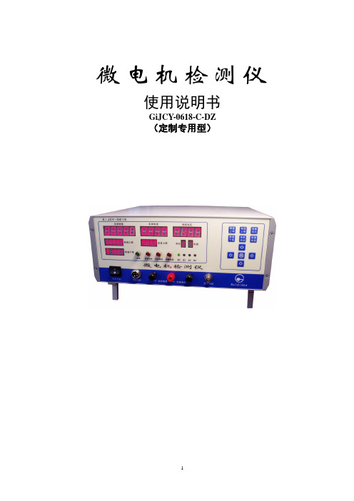
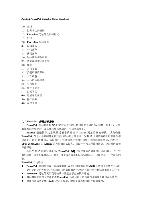
微电机检测仪使用说明书GiJCY-0618-C-DZ(定制专用型)GiJCY-0618-C-DZ 操作简介:1、设电机电压:按键,按选择位,按增减值。
按电机电压键,电机电压数码管00.01位闪动,按上、下箭头键,每4次增减0.01V左右;或按左箭头键,00.10位闪动,再按上、下箭头键,每次增减0.1V左右;或再按左箭头键,01.00位闪动,再按上、下箭头键,每次增减1V左右;依此操作,设定为所要求的电机电压值。
2、设转速上限:按键,按选择位,按增减值。
按转速上限键,转速上限数码管个位闪动,按上、下箭头键,每次增减1转;或按左箭头键,十位闪动,再按上、下箭头键,每次增减10转;或再按左箭头键,百位闪动,再按上、下箭头键,每次增减100转;依此操作,设定为所要求的转速上限值。
3、设转速上限:按键,按选择位,按增减值。
按转速下限键,转速下限数码管个位闪动,类似设置转速上限操作,设定为所要求的转速下限值。
4、设电流上限和电流下限:按键,再按一次键,看“实测电流”窗小数点亮或灭;灭表示“电流上限”,亮表示“电流下限”。
小数点灭时设置“电流上限”:按选择位,按增减值。
小数点亮时设置“电流下限”:按选择位,按增减值。
按电流上限键,电流上限0.001位闪动,按上、下箭头键,每次增减0.001A;或按左箭头键,0.010位闪动,再按上、下箭头键,每次增减0.01A;或再按左箭头键,0.100位闪动,再按上、下箭头键,每次增减0.1A;依此操作,设定为所要求的电机电流上限值。
5、设绝缘电压:按键,按增减值。
按功能1键,再按上箭头键,功能1数码管显示:0、1、2,三个数循环;0表示输出绝缘电压为100V,绝缘电阻小于5 MΩ报警;1表示输出绝缘电压为200V,绝缘电阻小于10MΩ报警;2表示输出绝缘电压为300V,绝缘电阻小于15MΩ报警;6、选工作模式M0/M2:按键。
M0标准模式:电机通电即启动检测,无控制脉冲输出。
深圳市维科特机电有限公司AM22070H说明书

深圳市维科特机电有限公司AM22070H产品说明书在86及110、130混合式步进电机的应用中(主要需求点为900RPM以内,高转矩、高响应、高性价比的定位控制,或者变频调速控制),三相混合式步进电机应用最为广泛。
但在某些国家(例如印度、土耳其、阿根廷等国),以及某些行业中(例如大中型木工雕机、单头绣花机、花样机等),由于使用习惯及发展历史等原因,依然采用两相步进电机及高压型两相步进电机驱动器。
传统模拟式两相步进电机驱动器由于控制算法、发热等方面的原因普遍使用交流110V供电,交流220V供电会导致电机发热非常厉害而无法使用;新型数字式两相步进电机驱动器在算法方面做了较大提升,即使工作在交流220V时,依然能够在发热、平稳性、稳定性等方面做到较好的平衡。
该驱动器使用最为典型的行业为单头绣花机、大幅面花样机、定长送料机、中大型木工雕刻机等。
AM22070以各行业客户对高压型2相步进电机驱动器的需求为目标,以行业应用经验为基础,以为客户提供高性价比、高稳定性的产品为宗旨。
整套控制方案在充分吸收和掌握国外先进技术的基础上进行深入优化和提炼而成。
硬件设计上充分考虑强弱电隔离、输入信号兼容、关键物料选用国际知名厂家经典、成熟的元器件;软件上采用自创的两相步进电机驱动器矢量控制技术及其快速算法,并具备自测试运行、单双脉冲模式设置、多重保护等功能。
特点单电源输入,电压范围:交流AC110-240V,相比传统110V供电的驱动器,可以省掉一个变压器,相同转速下输出力矩更大;驱动电流从有效值1.2A/相到7A/相分16档可调;16档细分配置,最高分辨率40000步/转;细分配置小于等于2000步/转时采用微细分控制方式;最高响应频率可达200KHz;相位记忆功能:断电时能自动记忆电机转子位置;保护功能:过热保护/过流保护、相间短路保护、断线保护、过压保护;自动半流:输入脉冲脉冲停止超过100ms时,电流自动减半,减少电机发热;全隔离:信号输入输出隔离;强弱电隔离(pwm控制信号及电流采样均隔离);5V/24V信号输入兼容设计;控制模式可选:脉冲/方向模式;或者双脉冲输入模式;自测试功能:无需外界脉冲信号即可驱动电机以30转/分钟的速度转动;体积为83x202x147(mm^3),推荐安装空间至少为100x230x200(mm^3);净重:1.5kg(加包装箱1.7kg);颜色:白色;采用工业级芯片设计,运行环境温度:-25゜~+60゜(0゜以下不结冰);采用矢量控制及微细分控制技术,在运行平稳性、噪音、震动、发热等方面较传统驱动器均有较大的提升;应用领域灌胶机木雕机激光切割机数控机床包装设备单头绣花机花样机缝纫机钻孔机电流设定驱动器工作电流IM(以下简称IM)由D1-D4拨码开关设定(注:工作电流为正常运行时的电流有效值给定,抱轴时的电流则为对应工作电流的50%,简称自动半流。
OKW电子外壳和调节旋钮说明书

ENCLOSURES AND OPERATING ELEMENTS FOR MEASUREMENTTECHNOLOGY32OKW electronic enclosures and tuning knobs meet the exacting standards requiredfor precision measurement, automation and control.Smart, ergonomic enclosures with application-specific accessories offer usersf atigue-free viewing and operation. Robust construction protectsyour electronics – even in harsh environments.Benefits for users include enhanced product quality, greater productivity,energy savings, and seamless monitoring and documentation.MEASURING TECHNOLOGYDEPENDS ON PRECISIONCONTROL-KNOBSAward-winning CONTROL-KNOBS for rotaryp otentiometers or encoders with round shaft ends (DIN 41591). Suitable for rotary/click functions in menu-driven interfaces. Proven collet fixture system.Optional multi-colour illumination with energy-saving SMD LED technology.APPLICATIONSOKW solutions are ideal for a wide rangeof manual and automated measuring applications:▪ m easuring physical, electromagnetic, electrical and other variables▪ d ata loggers and tracking systems ▪ t est equipment and detectors▪ m onitoring and control, alarm and emergency systems ▪ w earables▪ s mart devices for IoT, IIoT and IoMT ▪ c alibration devices and systems.CARRYTECCARRYTEC (IP 54 optional) is a large portable enclosure witha robust integrated handle that is comfortable to hold. The operating area can accommodate user interfaces from 8.4“ (21 cm) to 13.4“ (34 cm). At the rear there are mounting points for a tripod or suspension arm. Accessories include side-mounted cases for probes, sensors and other equipment.SOLID-BOXRobust IP 66/IP 67 enclosures with IK 08 impact protection,a V-0 flammability rating, and a large user interface.Deep recesses protect connectors, enabling your electronics to deliverp recise data accurately and reliably – even in challenging environments.5Award-winning wearable enclosuresin a huge range of shapes, sizes and colours. Easy to wear/attach.INTELLIGENT ENCLOSURES FOR enclosures for modern control units. Comfortable to hold. Easy-clean glossy surface. Moulded from UV-stable ASA or infrared-permeable PMMA. IP 65 protection optional.EASYTECFlanged enclosures for rapidmounting on walls and tubes/round profiles. Ideal for modern sensor applications.MINI-DATA-BOXSmart sensor enclosures with/ without flanges for fast mounting on walls, ceilings, rails and tubes.CONNECTIdeal for wired applications as well as mobile devices with battery operation, e.g. for measuringi nstruments, test systems etc.SOFT-CASEWide-format contoured enclosures for handheld, tabletop or wall-mounted UNITECDual-face enclosures with sloping dialo-gue areas (72° and 18°) for face-to-face together perfectly, enabling complex workflows to be controlled and implemented Our customisation services include assembly of cable glands and grommets – so your enclosures arrive ready for the installation of your electronics.SMART-CONTROLWedge-shaped enclosures for easy installation in corners. They can also BODY-CASEComfortable enclosures for personal electronics worn on or close to the body.9Industrial electronic enclosures with high impact resistance (IK 08) and ingress protection (IP 66, SECURE AND RELIABLE FOR CONTROL-KNOBSNew ergonomic CONTROL-KNOBS have a soft-touch surface which is easy to grip and feels comfortable in operation. The high- quality appearance – illuminated if required –d istinguishes this advanced range of tuning knobs PROTECSquare control centre enclosures for desk and wall electronics. Ideal for touchscreens. Choose from three versions.DATEC-COMPACTHandheld enclosures with a high protection class and robust design. Ideal for mobile measuring applications either indoors or outdoors.Handheld enclosures with a largehead section for bigger display modules. Narrow holding area for greater user comfort.High ingress protection up to IP 65 (XS, S), IP 54 (M, L)MINI-DATA-BOXTough industrial plastic enclosures up to IP65 with flanges for fast mounting to walls, ceilings, rails, tubes or masts.IN-BOXImpact-resistant ABS (OK 07) or PC (IK 08) enclosures for industrial electronics. Rated IP 66, IP 67. Also available with transparent lid.EVOTECWide range of robust enclosures (IP 65 optional) for contemporary tabletop/desktop electronics. Available with/without sloping top.SMART-TERMINALRobust and elegant extrudedaluminium/plastic enclosures for large assemblies.Custom lengths are available.1011IN-BOX POTTING BOXES TOP-KNOBS RAILTEC B/C SMART-CONTROL HAND-TERMINAL SENSO-CASE CARRYTEC DATEC-CONTROL BODY-CASE INTERFACE-TERMINAL EVOTEC MINITEC SNAPTEC SHELL-TYPE CASES STYLE-CASE NET-BOX PROTEC SMART-CASE DIATEC SMART-TERMINAL ROBUST-BOX TUNING KNOBS ‘CLASSIC’STANDARD PRODUCT RANGETOPTEC SLIM-CASE CONNECT ERGO-CASE DATEC-POCKET-BOX DATEC-MOBIL-BOX DATEC-COMPACTSOFT-CASE COMTEC SOLID-BOX DATEC-TERMINAL FLAT-PACK CASE COM-KNOBS DESK CASES UNITECART-CASECOMBINATION KNOBS EASYTEC SYNERGY STAR-KNOBS CONTROL-KNOBSSMART-BOXSMART-PANELMINI-DATA-BOX MEDITEC 1213>>>FROM STANDARD View our comprehensive standard range and select the enclosure or tuning knob that best matches your ideas, your components and the needs of your customers. Next simply tell us what you need for your product.Together we will discuss the modifications needed, your quality requirements, the price and delivery time.MACHININGEMC SHIELDINGMATERIALSLACQUERINGPRINTINGDECOR FOILSLASER MARKINGINSTALLATION/ASSEMBLYTOI N D I V I DUA LI T Y1415“INDIVIDUAL COLOURS”On request we can also produce many of our enclosures and tuning knobs in special colours. To match the colour you require, we can have the natural plastic material coloured and extruded toa high standard. Individual colour adjustments are possiblea ccording to a sample, RAL or Pantone shades.“V-0”Manufacturing of enclosuresin flame-retardant (V-0) plastic on request.SPECIAL MATERIALProtect your electronics from external interference, as well as from increased internal emission noise. We coat the inside of the enclosure with a luminium to shield plastic parts (which offer no natural p rotectionagainst electromagnetic radiation).EMC SHIELDINGLaser marking is ideal for individual labelling,i dentifying or marking – especially for very smallm achine-readable markings such as QR codes,b arcodes and DataMatrix codes. Consecutiven umbering of parts and the addition of individual texts/logos is quick and easy.LASER MARKINGSpecify printing to give your products a personal touch, and to indicate function and usage. With precision craftsmanship, we can carry out the required printing to your satisfaction. Depending on the printing format and type of enclosure, we can offer youscreen printing, tampo printing as well as digital printing.PRINTINGWe can lacquer the enclosures and tuning knobs in any colour you wish to suit your application orc ompany branding. OKW offers a wide choice of lacquers. They include soft-touch, metallic effects and ESD conductive lacquer to prevent electrostatic discharges.LACQUERINGWe can perform individual machining processes for you, quickly and reliably, for sample or series productionq uantities. You will receive your enclosures ready for the installation of your electronics. Milling, tapping, engraving, drilling, countersinking and stamping – there is practically no limit to the variety of shapes and designs.MACHININGFor lettering and colour design, we can digitally print product labels quickly and easily for small batches s tarting with one unit. Digital printing enables co nsecutive numbering, codes and technicals pecifications. Colour graduations are also possible.DECOR FOILSWe assemble your enclosure accessories including cable glands, belt/pocket clips, tilt foot bars, wall-mount kits, hinges, carry handles, keyboard foils, product labels, type plates, display windows, mounting pillars, seals and fibre-optics. The service also includes packaging to your specifications.ASSEMBLY OF ACCESSORIESCUSTOMISINGOdenwälder Kunststoffwerke Gehäusesysteme GmbH Friedrich-List-Str. 374722 Buchen/Germany Tel. +49 (0) 62 81 | 404-00*****************Web Turtle © by OKW Gehäusesysteme,Buchen, Germany.Subject to technical modificationwithout notice.DPMES23e | September 2023YOUR PARTNER:ASK FOR A SAMPLE!It‘s quick and easy online - just go to the OKW website, add the required enclosure/tuning knob version by clicking “Add to my basket … and tick “Sample …. Then add your contact details and send off the form. You will receive a confirmation of your request by email, and your sample will be on its way.。
微电机壳课设说明书.

机械制造工艺学课程设计说明书设计题目:方案11“微电机壳”零件的机械加工工艺规程设计及铣床专用夹具钻模的设计(成批生产)设计者:马赛班级: 0507103学号:*********学院:机电学院指导教师:钱晓明2010年6月25日目录一.课程设计的目的--------------------第2页二.课程设计的内容与要求-----------------第3^4页三.课程设计的步骤-----------------------第4~12页四.设计收获与感想---------------------------第12^14页五参考书目-----------------------—------------第14^15页一课程设计的目的机械制造工艺学课程设计是在学完了《机械制造工艺学》课程,进行生产实习之后的一个重要教学实践环节。
他要求学生综合应用本课程及有关先修课程(工程材料与热处理、机械设计、互换性与测量技术、金属切削机床、金属切削原理与刀具等)的理论以及在生产实习中学到的实践知识进行工艺规程设计,是毕业设计前的一次综合训练。
通过本次机械制造工艺学课程设计,应达到以下目的:1.学生能熟练运用“机械制造工艺学”课程中的基本理论以及生产实践中学到的实践知识,正确制定一个中等复杂零件的工艺规程。
2.学生能根据被加工零件的工艺规程,运用夹具设计的基本原理和方法,设计一套专用夹具。
3.培养学生熟悉并快速高效运用有关手册、标准、图表等技术资料的能力。
4.进一步培养了学生识图、制图、运算和编写技术文件的基本技能。
二.课程设计的内容与要求1. 根据给定的零件绘制零件图:“微电机壳”零件图(CAD绘制) 1张2. 绘制给定的零件机械加工工艺规程:“微电机壳”机械加工工艺规程(word绘制) 1套3. 设计零件某一道工序所需的机床夹具装配图:“微电机壳”铣底座底面的专用夹具的装配图(CAD绘制) 1套4. 设计夹具中主要零件图(非标准件)V型块(CAD绘制) 1张5.编写课程设计说明书“微电机壳”零件工艺规程设计及机床专用夹具的设计 1份三.课程设计的步骤1.零件“微电机壳”的工艺分析,画零件图①零件在产品中的地位和作用:给定零件是微电机壳,它的作用是作为微电机工作中的支架,在微电机的工作中起支承固定作用。
马达使用手册
Anadrill PowerPak Steerable Motor Handbook1.0 介绍1.1 钻井马达的发展1.2 PowerPak马达的设计和测试1.3 应用2.0 PowerPak马达描述2.1 顶部接头2.2 动力部分2.3 传动部分2.4 轴承部分和驱动轴2.5 弯壳部分和连接扣型3.0 作业3.1 常用参数3.2 狗腿严重度限制3.3 工作准备3.4 马达的现场操作3.5 空气钻井3.6 短半径钻井3.7 打捞马达4.0 地质导向系统5.0 操作参数6.0 司钻手册1。
2 PowerPak 的设计和测试PowerPak马达是根据DD的要求而设计的,特别需要强调的是,粗糙,朴素,已证明的技术已经转变为了在工作现场占优势的,可信赖的作业。
Anadrill 遵循使井底系统接近最小的噪音对MWD测量数据的干扰,以及确保PowerPak马达不会限制排量和其它的钻井作业的原则。
为期18个月的系统分析和部件测试计划开始于1990年。
这项综合计划包括全尺寸的的功率计和钻机操作测试,利用位于Texas Sugar Land 的Anadrill的先进的测试设备。
已设计一项工程维修计划,包括时间表和部件跟踪。
从早在1992年的采用开始,PowerPak马达已经连续地达到或接近设计目标,为了它的可靠性,操作和维修成本,而且,对于改进效率和降低钻井成本,已经建立了一个新的标准。
PowerPak马达特性●PowerPak导向马达设计有标准组件,以使它们能够在对MWD干扰最小的情况下适应更广泛的定向井作业。
可以通过马达部件的选择,优化其在任何一种钻井条件下的作业。
●PowerPak马达的泥浆润滑轴承特性适合恶劣的钻井环境。
●多种多样的定转子形状允许PowerPak马达可用于低速高扭和高速低扭这两种情况。
●地面可调节弯壳体(SAB)改进了效率,增加了在现场的钻井控制能力。
●锻钢驱动轴提高了马达的强度。
●密封的传动组合阻止泥浆污染,从而提高了马达寿命。
《微电机壳说明书》word版

机械制造工艺学课程设计说明书学校:武汉职业技术学院专业:机械制造与自动化班级:机制09304设计人员:黄翔指导教师:完成日期:2012-1-10设计题目“微电机壳”设计计算说明书(生产纲领40000件)设计内容:(1)产品零件图(2)产品毛坯图 1张;(3)机械加工工艺过程卡片 1套;(4)机械加工工序卡片 1套;(5)课程设计说明书 1份;目录序言 (4)一、零件的分析 (5)(一)零件的作用 (5)(二)计算生产纲领,确定生产类型 (7)(三)零件的工艺分析 (7)二、工艺规程设计 (8)(一)确定毛坯的制造形式 (8)(二)基面的选择 (8)(三)制定工艺路线 (9)(四)机械加工余量、工序尺寸及毛坯尺寸的确定 (17)(五)确定切削用量及基本工时 (12)三、夹具设计 (17)(一)制定相应的方案 (17)(二)工件加工精度分析 (17)四、课程设计心得体会 (20)五、参考文献 (21)附图1:零件二维图样 (5)序言机械制造工艺学课程设计是在学完了机械制造工艺学课程后,综合运用以前所学有关机械专业知识,进行零件加工工艺过程设计。
其目的在于巩固、加深扩展机械制造技术及其他有关先修课程的理论知识,把理论知识和生产实践相结合,能够独立分析问题、解决问题,以及初步具备中等复杂程度零件工艺规程的能力。
本设计包括两个部分内容:第一部分为生产纲领、生产类型、工艺性分析和零件图的审查。
第二部分为毛坯的选择,根据图纸具体地阐明了毛坯选择类型以及尺寸。
零件加工工艺规程设计是设计的核心部分,具体地列出了设计思路以及整个零件加工工艺过程。
它包括定位基准的选择、确定表面的加工方法、确定机械加工余量、工序尺寸及公差、机床设备及工艺设备的选择、确定切削用量与基本工时。
就我个人而言,我希望能通过这次课程设计对自己未来将从事的工作进行一次适应性训练,从中锻炼自己分析问题、解决问题的能力,为今后参加社会工作打下一个良好的基础。
微电机壳说明书(附带镗夹具设计及其CAD装配图)(精)
课程设计心得体会在老师的指导下顺利地完成了“微电机壳”的机械加工工艺编程的设计,并且认真地、有计划地按时完成设计任务。
此次设计,以机械加工工艺路线为主线,通过对零件图纸分析,初步拟订加工表面方法,进一步拟订加工方法并选择机械加工装备。
确定加工路线后,熟悉并运用相关手册查工艺参数,计算切削用量和加工工时。
将计算的数据以及加工方法、刀具、机床设备,填入工艺文件。
课程设计是我们专业课程知识综合应用的实践训练,这是我们迈向社会,从事职业工作前一个比不可少也是提升个人能力的过程。
通过这一周的课程设计,我更加深深的体会了解了“千里之行始于足下”这一佳话。
首先,万事开头难,但是我们必须脚踏实地的开始,了解设计整个过程的理念,以及设计零件的思想和计划方案,这样我们才能为明天稳健地在社会建设大潮中找到立足之地,为在大潮中奔跑打下坚实的基础。
通过课程设计,本组成员深深体会到干任何事都必须有耐心、细心。
课程设计过程中,有许多是要通过查阅手册获取数据和比较繁琐的计算,这些有时难免让人有些心烦意乱,但是千里之堤,溃于蚁穴,以及现实社会中的一些事实提醒自己,做事情要秉着负责任的态度,我从中得到了在工作作风上的一次难得磨练。
综合应用所学专业知识的能力还存在很多不足,正是有了这样的醒悟,我从中也是有了不少的收获,积累了一定的经验,为我在以后的学习和工作中给予很大的帮助。
第 26 页共 28 页参考文献[1]刘守勇.主编.机械制造工艺与机床夹具(第二版) . 机械工业出版社 . 刘守勇 .2009 [2]吴拓郧建国主编.机械制造工程(第二版) . 北京 .机械工业出版社 .2009 [3]孙本绪主编.机械加工余量手册. 北京 .国防工业出版社 .1999 [4]陈家芳主编.实用金属切削加工工艺手册(第二版) . 上海科学技术出版社.2005 [5]李必文主编.机械精度设计与检测.长沙.中南大学出版社.2011 [6]杨昂岳.机械制造工程学.长沙.国防科技大徐出版社.2004 [7]傅水根.机械制造工艺基础.北京.精华大学出版社.2010 [ 8 ] Grote, K -H 、 Feldhusen, J 、 Grote, Karl-Heinrich 、 Feldhusen.Dubbel: Taschenbuch Fur Den Maschinbenau . Jorg Springer-Verlag Berlin and Heidelberg GmbH & Co. K . 2004 [9] Die Technologie Des Eisens: Handbuch Fur Den Praktischen Maschinenbau Und Die Stahlwaren- Und Kleineisendustrie. Anonymous. Nabu Press.2010 第 27 页共 28 页机械 09 本(2班机械加工工艺过程卡材料牌 HT200 毛坯种类号工工序名称工序内容序号 10 20 30 40 50 60 70 80 铸造毛坯热处理划线铣底面 A 铣底面台阶面钻扩底面孔车端面粗镗肋板内表面半精镗肋板内表面铸件产品型号产品名称毛坯外形尺寸车工间段铸钳机机机车机零件图号零件名称每毛坯件数设备工艺装备 KSCJ-02 微电机壳 1 每台件数共1页 1 备注第1页年产 10 万工时准单终件外协时效处理对要加工的 6 个底面孔及 2 个螺纹孔进行划线 0.1 铣底面 C 至尺寸 65 0.4 mm A6132 A6132 Z535 立式钻床 CA6140 T618 铣底面台阶面保证尺寸 24mm 钻底面孔Φ8mm;锪沉头孔Φ12mm 车零件1220 - 0.63 mm 两端面圆粗镗φ102f9 的内圆表面至0.20 mm;101.50 专用夹具、硬质合金端面铣刀、游标卡尺专用夹具、硬质合金端面铣刀、游标卡尺专用夹具、麻花钻、扩孔钻、锪孔刀、内径千分尺专用夹具、硬质合金车刀、游标卡尺专用夹具、车刀、内径千分尺 90 半精镗φ102f9 的内圆表面至0.087 mm 102. 0 机T618 专用夹具、车刀、内径千分尺 100 110 120 130 140 钻螺纹孔钻 M4-7H 中底孔和Φ10mm 的通孔攻螺纹攻螺纹冲箭头检验入库 2 次攻 M4-7H 的螺纹通孔机机 6 次攻两端面Φ111mm 上的 M5-7H 的螺机纹孔,深度为 12mm Z535 立钻Z535 立钻 Z535 立钻专用夹具、麻花钻、扩孔钻、内径千分尺专用夹具、攻丝刀、内径千分尺专用夹具、攻丝刀、内径千分尺设计 (日期标记处数更改文件号签字日期标记处数更改文件号签字日期校对 (日期审核 (日期标准化(日期)会签 (日期第 28 页共 28 页。
扁平振动马达 VC0720B001F 规格书说明书
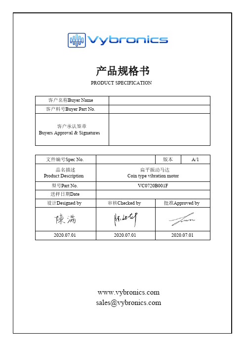
产品规格书PRODUCT SPECIFICATION 客户名称Buyer Name1.重要提示/Importance Notes2.更改记录/Revised Record3.试用范围/Application4.试用条件/Operation condition1.重要提示 Importance Notes:1)如对电机的性能和If there is any argument on motor performance and/or life, judgment is to be made base on this specification only.2)客户方有责任确认该电机能满足您的使用要求。
Customer has the responsibility to ensure that the motor can satisfy the requirement of your application.3.试用范围/Application本说明书适用于扁平式永磁直流电机This specification applies to coin type permanent-magnetic motors DC model 4.试用条件/Operating Condition项目/Item6.电子特性/Electrical Characteristics项目/Item6-1额定转速/Rated speed6-2额定电流/Rated current6-3启动电/Starting voltage8.可靠性试验 /Reliability TestNO. Item8-1寿命/Life time10.注意事项/Cautions10-1 必须按照规格书标准使用围。
Unless it is usedconsiderably reduced. Due attention should be paid to voltage and range for use. 10-2 建议马达在六个月内使用1.高温和高湿的场所;2.腐蚀性气体,如:11.包装/Packing Require12.外形图/Motor Outline Drawing。
Eaton NGC208032E电子纤维壳电路保护器说明说明书
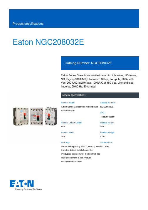
Eaton NGC208032EEaton Series G electronic molded case circuit breaker, NG-frame, NG, Digitrip 310 RMS, Electronic LSI trip, Two-pole, 800A, 480 Vac, 200 kAIC at 240 Vac, 100 kAIC at 480 Vac, Line and load, Imperial, 50/60 Hz, 80% ratedGeneral specificationsEaton Series G electronic molded case circuit breakerNGC208032E 7866856095606 in9 in9 in 47 lb Eaton Selling Policy 25-000, one (1) year from the date of installation of the Product or eighteen (18) months from the date of shipment of the Product, whichever occurs first.UL Listed Product NameCatalog NumberUPCProduct Length/Depth Product Height Product Width Product Weight WarrantyCertificationsSeries G100 kAIC at 480 Vac 200 kAIC at 240 VacNGNG80% ratedComplete breakerLine and load480 Vac800 AElectronic LSITwo-pole Application of Multi-Wire Terminals for Molded Case Circuit Breakers Application of Tap Rules to Molded Case Breaker TerminalsHigh performance operating handles for Series G circuit breakers product aidSeries G MCCB quick selectorMulti-wire lugs product aidCircuit breaker motor operators product aidPower metering and monitoring with Modbus RTU product aidCurrent limiting molded case circuit breaker module product aid Current limiting molded case circuit breaker module for series G, JG and CLMotor protection circuit breakers product aidPlug-in adapters for molded case circuit breakers product aidMolded case circuit breakers providing higher levels of selective coordination product aidStrandAble terminals product aidComprehensive circuit protection for control panel applicationsJ-Frame 310+ and L-Frame 310+ Molded-case circuit breakers Breaker service centersMolded case circuit breakers catalogEaton's Volume 4—Circuit ProtectionInstruction Leaflet for Drawout Cassette for NG Frame Circuit BreakersNG and ND-Frame molded case circuit breakersEaton Specification Sheet - NGC208032EMOEM MCCB product selection guideSeriesInterrupt ratingFrameCircuit breaker type RatingCircuit breaker frame type TerminalsVoltage rating Amperage RatingTrip TypeNumber of poles Application notesBrochuresCatalogsInstallation instructions Specifications and datasheetsEaton Corporation plc Eaton House30 Pembroke Road Dublin 4, Ireland © 2023 Eaton. All Rights Reserved. Eaton is a registered trademark.All other trademarks areproperty of their respectiveowners./socialmedia。
连接座夹具课程设计说明书

③.磨具的选用:磨具通常又称为砂轮。是磨削加工所使用的“刀具”。磨具的性能主要取决于磨具的磨料、结合剂、粒度、硬度、组织以及砂轮的形状和尺寸。参考《简明机械加工工艺手册》(主编 徐圣群) 表12-47,选择双斜边二号砂轮。
表3-2 成批和大量生产铸件的尺寸公差等级
铸造方法
公差等级CT
灰铸铁
砂型手工造型
11~13
砂型机器造型及壳型
8~10
金属型
7~9
低压铸造
7~9
熔模铸造
5~7
根据上表选择金属型公差等级为7级。
3-3 铸件尺寸公差数值
铸件基本尺寸
公差等级CT
大于
至
8
63
100
160
100
160
250
1.6
1.8
2.0
根据上表查得铸件基本尺寸大于100 至160 ,公差等级为8级的公差数值为1.8 。
上述两个方案的特点在于:方案一的定位和装夹等都比较方便,但是要更换多台设备,加工过程比较繁琐,而且在加工过程中位置精度不易保证。方案二减少了装夹次数,但是要及时更换刀具,因为有些工序在车床上也可以加工,镗、钻孔等等,需要换上相应的刀具。而且在磨削过程有一定难度,要设计专用夹具。因此综合两个工艺方案,取优弃劣,具体工艺过程如下:
就我个人而言,我希望能通过这次毕业设计对自己未来将从事的工作进行一次适应性的训练,希望在设计过程中能锻炼自己分析问题、解决问题的能力,为自己今后参加祖国的“四化”建设打下一个良好的基础。
由于能力有限,设计尚有许多不足之处,希望各位老师给予指教。
微电机壳课程设计书

机械制造工艺学课程设计说明书课题:班级:姓名:指导老师:完成日期:《机械制造工艺与机床夹具》课程设计任务书设计题目:自选零件(可以参考所用的教材中的零件)机械加工工艺规程的编制及工装设计生产纲领:年产量为大批量10000件课程设计内容:1、按相应的比例绘制零件图1 张2、按相应的比例绘制零件毛坯图1张(可放在说明书中)。
3、编制机械加工工艺过程卡片1份。
按指导书规定格式填写。
4、机械加工工序卡设计。
按给定的规定格式填写。
5、夹具设计,绘制装配图1张(1号或0号)。
6、课程设计说明书1份(A4页面,右侧留出5cm的空格)课程设计说明书结构要求:1、封面2、摘要3、目录4、正文5、结论说明:1. 说明书的结构顺序,要包含以上五个方面;2. 说明书除封面外,其余每页均需有页码;3.正文部分的每部分标题按要求书写:一级标题:1二级标题:1.1三级标题:1.1.1班级:08机械1、2、3班指导教师:张明秋教研室:机械教研室2010年11月30日摘要1.1 零件的分析 (1)1.1.1 零件的作用 (1)1.1.2 零件的工艺分析 (1)1.2 工艺规程的设计 (2)1.2.1 确定毛坯的制造形式 (2)1.2.2 基面的选择 (2)1.2.3 制造工艺路线 (3)1.2.4 机械加工余量、工序尺寸及毛坯的确定 (3)1.2.5 切削用量确定及基本工时 (3)1.3 夹具的设计 (4)1.3.1 制定设计方案 (4)1.3.2 确定定位方法、选定位元件 (4)1.3.3 确定夹紧方案、设计夹紧结构 (5)1.3.4 定位误差分析 (5)1.4 结论 (6)1.5 参考文献 (7)机械加工工艺学科是进行生产实习的一个重要教学环节。
对课程的设计至关重要。
微电机壳是设计的薄壁件,其构造为底座四个通孔、内表面六个凸台和断面上六个螺纹孔,便于零件上的安装。
其作用是为转子和定子起保护作用,用途广泛。
就个人而言,在对微电机壳的设计过程中,有定位基准的选择确定加工各表面所需工时,每到工序所选机床的切削速度、进给量以及刀具的选则都是事关重要的,尤其夹具的定位夹紧在每到工序上都有不同的要求。
微电机壳工艺规程设计说明书

微电机壳工艺规程设计说明书微电机壳工艺规程设计说明书一、设计背景微电机是一种小型电机,广泛应用于电子产品、机械设备等领域。
工艺规程是指在产品生产过程中,为保证产品质量和生产效率,制定的一系列操作规范和工艺流程。
二、设计目标本设计旨在制定一份完善的微电机壳工艺规程,以确保微电机壳的加工质量和生产效率达到预期的要求。
三、设计内容1. 工艺流程的确定:确定微电机壳的加工工艺流程,包括钣金加工、打孔、折弯、冲压等环节,并明确每个环节的先后顺序。
2. 工艺参数的设定:根据产品设计要求,确定各个加工环节的具体参数,包括钣金板材的厚度、打孔尺寸、折弯角度、冲压力度等。
3. 设备和工装的选择:根据工艺流程和要求,选择适合的加工设备和工装,确保能够满足加工质量和生产效率的要求。
4. 操作规范的制定:制定每个加工环节的操作规范,包括操作步骤、注意事项、安全规范等,以便操作人员能够正确、安全地进行加工。
5. 质量控制措施的确定:确定质量控制措施,包括对材料的检验、工艺过程的控制和成品的检验等,以确保加工出来的微电机壳符合产品设计要求。
6. 设备维护要求的明确:明确每台设备的维护要求,包括定期保养、故障排除等,以确保设备能够保持良好的工作状态。
四、设计步骤1. 分析微电机壳的产品设计要求和生产需求,确定加工工艺流程。
2. 根据产品设计要求和工艺流程,设定各个加工环节的工艺参数。
3. 根据工艺参数和要求,选择适合的加工设备和工装。
4. 制定每个加工环节的操作规范,包括操作步骤、注意事项、安全规范等。
5. 确定质量控制措施,包括对材料的检验、工艺过程的控制和成品的检验等。
6. 明确每台设备的维护要求,包括定期保养、故障排除等。
五、设计要点1. 工艺流程的设计要合理,避免加工过程中出现漏工、重工等问题。
2. 工艺参数的设定要准确,确保加工出来的微电机壳符合产品设计要求。
3. 操作规范的制定要详细,包括操作步骤、注意事项、安全规范等。
超微电脑SC846空气壳用户指南说明书
SC846 Air ShroudUser’s GuideRevison 1.0SC846 Air Shroud User’s Guide The information in this User’s Guide has been carefully reviewed and is believed to be accurate. The vendor assumes no responsibility for any inaccuracies that may be contained in this document, makes no commitment to update or to keep current the information in this manual, or to notify any person ororganization of the updates. Please Note: For the most up-to-date version of this manual, please see our web site at .Super Micro Computer, Inc. (“Supermicro”) reserves the right to make changes to the product described in this manual at any time and without notice. This product, including software, if any, and documentation may not, in whole or in part, be copied, photocopied, reproduced, translated or reduced to any medium or machine without prior written consent.IN NO EVENT WILL SUPERMICRO BE LIABLE FOR DIRECT, INDIRECT, SPECIAL, INCIDENTAL, SPECULATIVE OR CONSEQUENTIAL DAMAGES ARISING FROM THE USE OR INABILITY TO USE THIS PRODUCT OR DOCUMENTATION, EVEN IF ADVISED OF THE POSSIBILITY OF SUCHDAMAGES. IN PARTICULAR, SUPERMICRO SHALL NOT HAVE LIABILITY FOR ANY HARDWARE, SOFTWARE, OR DATA STORED OR USED WITH THE PRODUCT, INCLUDING THE COSTS OF REPAIRING, REPLACING, INTEGRATING, INSTALLING OR RECOVERING SUCH HARDWARE, SOFTWARE, OR DATA.Any disputes arising between manufacturer and customer shall be governed by the laws of Santa Clara County in the State of California, USA. The State of California, County of Santa Clara shall be theexclusive venue for the resolution of any such disputes. Super Micro's total liability for all claims will not exceed the price paid for the hardware product.FCC Statement: This equipment has been tested and found to comply with the limits for a Class A digital device pursuant to Part 15 of the FCC Rules. These limits are designed to provide reasonable protection against harmful interference when the equipment is operated in a commercial environment. This equipment generates, uses, and can radiate radio frequency energy and, if not installed and used in accordance with the manufacturer’s instruction manual, may cause harmful interference with radiocommunications. Operation of this equipment in a residential area is likely to cause harmful interference, in which case you will be required to correct the interference at your own expense.California Best Management Practices Regulations for Perchlorate Materials: This Perchlorate warning applies only to products containing CR (Manganese Dioxide) Lithium coin cells. PerchlorateMaterial-special handling may apply. See /hazardouswaste/perchlorate for further details.Manual Revison 1.0Release Date: April 21, 2009Unless you request and receive written permission from Super Micro Computer, Inc., you may not copy any part of this document.Information in this document is subject to change without notice. Other products and companies referred to herein are trademarks or registered trademarks of their respective companies or mark holders.Copyright © 2009 by Super Micro Computer, Inc.All rights reserved.Printed in the United States of America WARNING: HANDLING OF LEAD SOLDER MATERIALS USED IN THISPRODUCT MAY EXPOSE YOU TO LEAD, A CHEMICAL KNOWN TO THESTATE OF CALIFORNIA TO CAUSE BIRTH DEFECTS AND OTHERREPRODUCTIVE HARM.PrefaceAbout this ManualThis manual is written for professional system integrators, Information Technology professionals, service personnel and technicians. It provides information for the installation and use of Supermicro's SC846 air shroud. Installation and maintenance should be performed by experienced professionals only.Manual OrganizationChapter 1: IntroductionThe first chapter provides a checklist of the main components included with the SC846 air shroud and describes its main features.Chapter 2: System SafetyYou should familiarize yourself with this chapter for a general overview of safety precautions that should be followed when installing and servicing the SC846 air shroud. Chapter 3: Configuration and InstallationRefer here for details on installing the SC846 air shroud on a computer system mainboard.SC846 Air Shroud User’s GuideNotes:Table of ContentsChapter 1 Introduction.......................................................................1-1 1-1 Overview.............................................................................................1-1 1-2 Product Checklist of Typical Components.....................................1-1 1-3 Features..............................................................................................1-2 1-4 Returning Merchandise for Service................................................1-2 1-5 Contacting Supermicro.....................................................................1-3 Chapter 2 System Safety..................................................................2-1 2-1 Electrical Safety Precautions...........................................................2-1 2-2 General Safety Precautions.............................................................2-2 2-3 Electrostatic Discharge Precautions..............................................2-2 2-4 Operating Precautions......................................................................2-2 Chapter 3 Configuration and Installation...............................3-1 3-1 Overview.............................................................................................3-1 3-2 SC846 Air Shroud Components.....................................................3-1 Component Part B..................................................................................3-2 Component Part C..................................................................................3-3 3-3 Removing Breakable Sections for Cabling...................................3-5 3-4 Configuring the SC846 Air Shroud.................................................3-6 Configuring for Configuration-1...............................................................3-7 Configuring for Configuration-2...............................................................3-8 Configuring for Configuration-3...............................................................3-9 3-5 Installing the SC846 Air Shroud....................................................3-10SC846 Air Shroud User’s GuideNotesChapter 1Introduction1-1OverviewThe SC846 air shroud is a configurable air shroud for system mainboards to enable maximum efficient air flow through the system. It can be configured to fit different sized Intel® Xeon™ DP 5500/5400/5100/5000 series system mainboards of the same general shape and size. The SC846 air shroud is optimized for use with Supermicro SC846 series chassis designs and for Supermicro X8Dxx/X7Dxx series mainboards. SeeChapter 3 for configuration details.1-2Product Checklist of Typical Components The SC846 air shroud comes packaged with components and parts as shown inTable 1-1:Table1-1. SC846 Air Shroud Parts and ComponentsPart Number Description Quantity MCP-310-48003-0N SC846 Intel DP plastic air shroud, supports up to 18 memory DIMM slotsMCP-310-48004-1N SC846 X8 air shroud component part A 1MCP-310-48005-1N SC846 X8 air shroud component part B1MCP-310-28005-1N X8 air shroud universal component part C1MCP-310-28006-1N X8 air shroud universal component part D, tear-drop Mylarmodule, 2.2” (55mm) wide1NOTE: The default configuration is for parts A, B, C and D connected.NOTE: Each individual part for the SC846 air shroud is labeled with its component part letter for easy identification.SC846 Air Shroud User’s Guide1-3FeaturesThe SC846 air shroud includes the following features:•Main air shroud component•Three detachable components for creating multiple configurations•Breakable section for power cable management•Clear plastic material construction for ease of viewing1-4Returning Merchandise for ServiceA receipt or copy of your invoice marked with the date of purchase is required beforeany warranty service will be rendered. You can obtain service by calling your vendor fora Returned Merchandise Authorization (RMA) number. When returning to themanufacturer, the RMA number should be prominently displayed on the outside of the shipping carton, and mailed prepaid or hand-carried. Shipping and handling charges will be applied for all orders that must be mailed when service is complete.For faster service, RMA authorizations may be requested online at:http://www. /support/rma/Whenever possible, repack the chassis in the original Supermicro carton, using the original packaging material. If these are no longer available, be sure to pack the chassis securely, using packaging material to surround the chassis so that it does not shift within the carton and become damaged during shipping.This warranty only covers normal consumer use and does not cover damages incurred in shipping or from failure due to the alteration, misuse, abuse or improper maintenance of products.During the warranty period, contact your distributor first for any product problems.Chapter 1: Introduction 1-5Contacting SupermicroHeadquartersAddress:Super Micro Computer, Inc.980 Rock Ave.San Jose, CA 95131 U.S.A.Tel:+1 (408) 503-8000Fax:+1 (408) 503-8008Email:************************(GeneralInformation) **********************(TechnicalSupport)Web Site:EuropeAddress:Super Micro Computer B.V.Het Sterrenbeeld 28, 5215 ML‘s-Hertogenbosch, The Netherlands Tel:+31 (0) 73-6400390Fax:+31 (0) 73-6416525Email:*******************(GeneralInformation) *********************(TechnicalSupport) *****************(CustomerSupport)Asia-PacificAddress:Super Micro Computer, Inc.4F, No. 232-1, Liancheng Rd.Chung-Ho 235, Taipei CountyTaiwan, R.O.C.Tel:+886-(2) 8226-3990Fax:+886-(2) 8226-3991Web Site: Technical Support:Email:**********************.tw Tel:+886-2-8228-1366, ext. 132 or 139SC846 Air Shroud User’s GuideNotesChapter 2System SafetyPlease read and follow all safety precautions below before using your Supermicro product.2-1Electrical Safety PrecautionsBasic electrical safety precautions should be followed to protect yourself from harm and the server from damage:•Be aware of how to power on/off the enclosure power supplies and the individual blades as well as the room's emergency power-off switch, disconnection switch or electrical outlet. If an electrical accident occurs, you can then quickly remove power from the system.•Do not work alone when working with high voltage components.•Power should always be disconnected from the blade module when removing or installing such system components as the mainboard, memory modules and processors.•When working around exposed electrical circuits, another person who is familiar with the power-off controls should be nearby to switch off the power if necessary.•Use only one hand when working with powered-on electrical equipment. This is to avoid making a complete circuit, which will cause electrical shock. Use extreme caution when using metal tools, which can easily damage any electrical components or circuit boards they come into contact with.•Do not use mats designed to decrease electrostatic discharge as protection from electrical shock. Instead, use rubber mats that have been specifically designed as electrical insulators.•The power supply power cords must include a grounding plug and must be plugged into grounded electrical outlets. Power input requires 110-240 VAC, depending upon your power supply module.•Mainboard Battery: This battery must be replaced only with the same or an equivalent type recommended by the manufacturer (CR2032 Lithium 3V battery). Dispose of used batteries according to the manufacturer's instructions. •Mainboard replaceable soldered-in fuses: Self-resetting PTC (Positive Temperature Coefficient) fuses on the mainboard must be replaced by trained service technicians only. The new fuse must be the same or equivalent as the one replaced. Contact technical support for details and support. WARNING: There is a danger of explosion if the onboard battery is installed upside down, which will reverse its polarities.SC846 Air Shroud User’s Guide2-2General Safety PrecautionsFollow these rules to ensure general safety:•Keep the area around the server clean and free of clutter.•Place the blade module cover and any system components that have been removed away from the system or on a table so that they won't accidentally be stepped on.•While working on the system, do not wear loose clothing such as neckties and unbuttoned shirt sleeves, which can come into contact with electrical circuits or bepulled into a cooling fan.•Remove any jewelry or metal objects from your body, which are excellent metal conductors that can create short circuits and harm you if they come into contact with printed circuit boards or areas where power is present.•After accessing the inside of the system, replace the blade module's cover before installing it back into the blade enclosure.2-3Electrostatic Discharge PrecautionsElectrostatic discharge (ESD) is generated by two objects with different electricalcharges coming into contact with each other. An electrical discharge is created toneutralize this difference, which can damage electronic components and printed circuit boards.The following measures are generally sufficient to neutralize this difference beforecontact is made to protect your equipment from ESD:•Use a grounded wrist strap designed to prevent static discharge.•Keep all components and printed circuit boards (PCBs) in their antistatic bags until ready for use.•Touch a grounded metal object before removing the board from the antistatic bag.•Do not let components or PCBs come into contact with your clothing, which may retain a charge even if you are wearing a wrist strap.•Handle a board by its edges only; do not touch its components, peripheral chips, memory modules or contacts.•When handling chips or modules, avoid touching their pins.•Put the mainboard and peripherals back into their antistatic bags when not in use.•For grounding purposes, make sure the blade enclosure provides excellent conductivity between the power supplies, the blade modules and the mainboard.2-4Operating PrecautionsCare must be taken to assure that the cover of the blade unit is in place when the blade is operating to assure proper cooling. Out of warranty damage to the blade can occur if this practice is not strictly followed.Any drive carrier without a hard drive installed must remain fully installed in the drive bay when the blade module is operating to ensure proper airflow.Chapter 3Configuration and Installation3-1OverviewThis chapter covers the configuration and installation of the SC846 air shroud into a server or into a chassis. The main section (component part A) can be connected to other sections (component parts B, C, and D) to make up to three configurations(Configuration-1 through Configuration-3).3-2SC846 Air Shroud ComponentsFigure 3-1. SC846 Air Shroud ComponentsSC846 Air Shroud User’s GuideTable3-1. SC846 Air Shroud ComponentsItem DescriptionA SC846 X8 air shroud component part AB SC846 X8 air shroud component part BC X8 air shroud universal component part CD X8 air shroud universal component part D, tear-drop Mylar module 2.2” (55mm) wideThe SC846 air shroud comes with three detachable components (Figure3-1 andTable 3-1). See below for details on these various components.These components can be used to create three configurations for use in Intel Xeon DP 5500/5400/5100/5000 series systems. The SC846 air shroud is optimized for use with Supermicro X8Dxx and X7Dxx series mainboards. See Section3-4 for further details on configurations.Component Part BFigure 3-2. Moving Component Part BThe SC846 air shroud’s component part B can be moved in and out to resize the air shroud’s size to fit the mainboard (Figure3-2).Chapter 3: Configuration and InstallationComponent Part CThe SC846 air shroud’s component part C (Figure 3-3) can be mounted on the inside of component part A. It is attached and secured by placing locking tabs on its top into alignment slots provided on component part A, as shown in the figure.Figure 3-3. Component Part CNOTE: The view in Figure 3-3 has been modified in order to show thealignment slots more clearly.SC846 Air Shroud User’s GuideComponent Part DFigure 3-4. Component Part DThe SC846 air shroud’s component part D (2.2” (55mm) wide tear-drop Mylar module), (Figure3-4) can be mounted on the underside of component part A by inserting its locking tabs into the component part A alignment slots provided.Chapter 3: Configuration and Installation 3-3Removing Breakable Sections for CablingFigure 3-5. Removing the Breakable TabsComponent part A for the SC846 air shroud has breakable tabs that can be permanently removed to allow cabling access if required for your system. Also component parts B and C have breakable tabs that perform the same function. See Figure3-5 for details.To remove, simply cut or break the tabs or section off from its attachments with a pair of scissors and discard them.SC846 Air Shroud User’s Guide 3-4Configuring the SC846 Air ShroudThe SC846 air shroud is customizable into three configurations for 4U Supermicro SC846 series chassis systems (see Table 3-2).See the sections below for instruction on configuring the SC846 air shroud to these various configurations.Table 3-2. SC846 Air Shroud ConfigurationsConfigurationDescription Configuration-1Component parts A, B, C and for Intel Xeon DP 5500/5400/5100/5000 series systems with 12” x 13” form factor mainboards, 6 PCI slots and up to 12 memoryDIMM slots (optimized for use with Supermicro X8Dxx/X7Dxx seriesmainboards).Configuration-2Component parts A, B, C and for Intel Xeon DP 5500/5400/5100/5000 seriessystems with 12” x 13” form factor mainboards, 7 PCI slots and up to 12 memoryDIMM slots (optimized for use with Supermicro X8Dxx/X7Dxx seriesmainboards).Configuration-3Components parts A, B, D and E (x1) for Intel Xeon DP 5500/5400/5100/5000series systems with 13.68” x 13” form factor mainboards, up to 18 memory DIMMslots (optimized for use with Supermicro X8Dxx+/X7Dxx+ series mainboards).NOTE: The default configuration is Configuration-1 with parts A, B, C and Dalready connected.For purposes of this section’s instructions assume that all parts areunconnected and assembly to one of the air shroud’s configurations is required for use.Chapter 3: Configuration and Installation Configuring for Configuration-1Figure 3-6. Configuration-1 (Default)To configure the SC846 air shroud for an Intel Xeon DP 5500/5400/5100/5000 series systems with 6 PCI add-on card slots, 12/8/4 memory DIMM slots and a 12” x 13” form factor, use Configuration-1. This configuration attaches component part B flush with the edge of component part A, and mounts component parts C and D to the underside of component part A (see Figure3-6).This configuration is optimized for use with Supermicro X8Dxx/X7Dxx series mainboards.SC846 Air Shroud User’s GuideConfiguring for Configuration-2Figure 3-7. Configuration-2To configure the SC846 air shroud for an Intel Xeon DP 5500/5400/5100/5000 series systems with 7 PCI add-on card slots, 12/8/4 memory DIMM slots and a 12” x 13” form factor, use Configuration-2. This configuration attaches component part B one slotdeeper than the edge of component part A, and mounts component parts C and D to the underside of component part A (see Figure3-7).This configuration is optimized for use with Supermicro X8Dxx/X7Dxx seriesmainboards.Chapter 3: Configuration and InstallationConfiguring for Configuration-3To configure the SC846 air shroud for an Intel Xeon DP 5500/5400/5100/5000 series systems with a 13.68”x 13”, 18 or 16 memory DIMM slots form factor, useConfiguration-3. This configuration attaches component part B one slot deeper than the edge of component part A, and mounts component parts D to the underside of component part A (see Figure 3-8).This configuration is optimized for use with Supermicro X8Dxx+/X7Dxx+ series mainboards.Figure 3-8. Configuration-3NOTE: Component part C is detached from this configuration.SC846 Air Shroud User’s Guide3-5Installing the SC846 Air ShroudTo install the SC846 air shroud follow the procedure below. This procedure is the same for all configurations of the SC846 air shroud in 4U systems.Installing the SC846 Air Shroud in SC846 Chassis Systems1.Configure the air shroud to fit in your system. See Section3-4 for details onconfiguring the air shroud.2.Secure the forward edge of the SC846 to the forward part of the chassis interior sothat the SC846 mounting tabs are locked in with the mounting slots of the chassis(see Figure3-9).Figure 3-9. Inserting Air Shroud onto a System MainboardChapter 3: Configuration and Installation3.Make sure the SC846 air shroud is mounted directly on the mainboard of its systemso that the air shroud covers the system mainboard over the CPU’s and memory slots (see Figure 3-10).4.Secure the top cover back on your system.Figure 3-10. Air Shroud Mounted in SystemNOTE: The air shroud should be mounted flush with the power supply housing if installing properly and that some cable is supposed to go under the airshroud.Power Supplyto ChassisSC846 Air Shroud User’s GuideNotesDisclaimerThe products sold by Supermicro are not intended for and will not be used in life support systems, medical equipment, nuclear facilities or systems, aircraft, aircraft devices, aircraft/emergency communication devices or other critical systems whose failure to perform be reasonably expected to result in significant injury or loss of life or catastrophic property damage. Accordingly, Supermicro disclaims any and all liability, and should buyer use or sell such products for use in such ultra-hazardous applications, it does so entirely at its own risk. Furthermore, buyer agrees to fully indemnify, defend and hold Supermicro harmless for and against any and all claims, demands, actions, litigation, and proceedings of any kind arising out of or related to such ultra-hazardous use or sale.SC846 Air Shroud User’s GuideNotes。
伊顿338 2C 2C EFD手动电机起动开关和外壳说明书
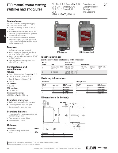
US: 1-866-764-5454 CAN: 1-800-265-0502 Copyright 2022 Eaton3382C2EFD manual motor starting switches and enclosuresCl. I, Div. 1 & 2, Groups B A , C, D Cl. II, Div. 1, Groups E, F, G Cl. II, Div. 2, Groups F, G Cl. IIINEMA 3, 7B A CD, 9EFG, 12Explosionproof Dust-ignitionproof RaintightWet LocationsEFD dead endEFDC through feedApplications:EFD manual motor starting and stopping switch enclosures are used:• For manual starting of small AC or DC motors• In locations made hazardous due to the presence of flammable vapors, gases or highly combustible dusts• For installation at petroleum refineries, chemical and petrochemical plants and in other process industry facilities where similar hazards existFeatures:• Enclosure is small and compact• Accurately ground flange on both body and cover for flametight joint• Switch can be padlocked in either START or STOP positions• Dead end (EFD) or through feed (EFDC) hubs in 3/4” to 1” sizeCertifications and compliances:NEC/CEC:• Class I, Division 1 & 2, Groups B A , C, D • Class II, Division 1, Groups E, F, G • Class II, Division 2, Groups F, G • Class III UL standard:• UL1203CSA standard:• C22.2 No. 30Environmental ratings:• NEMA 3, 7B A CD, 9EFG, 12Standard materials:• Bodies and covers – Feraloy iron alloy • Operating handle – type 6/6 nylon • Operating shaft – stainless steelStandard finishes:• Feraloy iron alloy – electrogalvanized and aluminum acrylic paint• Type 6/6 nylon – natural (black)• Stainless steel – naturalDimensions B(in inches):Electrical ratings:(Without overload protection; with switches)Ordering information:A Add GB suffix. Seals must be installed within 1/” of each conduit opening for Group B usage.B Dimensions are approximate, not for construction purposes.Options:Description Suffix • For use in Group B hazardousareas ..................................................GBANo. of polesTypeSwitch rating amperageHorsepower2Square D Class 251030A, 250 VAC;115 VAC, 230 VAC, 460-575 VAC, Dead end No. of polesHub sizeCat. # With switch 3/"EFD218 T8Through feed No. of polesHub sizeCat. # With switch 3/"EFDC218 T8Hub size h a3/"7/13/。
牙科微电机手柄使用说明书
1.5 Campo de aplicación Este producto debe operar con una unidad de micro motor (Favor igualar con una correcta pieza de mano o contra ángulo cuando use el modelo HS‐3), este es un equipo pulidor y amolador usado en, laboratorios dentales para amolar y pulir dentaduras, metales, base de prótesis, materiales inorgánicos, etc.
Figura 5
3.3.5 Después funcione la pieza de mano bajo no estado de carga sobre 20,000RPM por 30 minutos, entonces úselo.
3.3.6 El ciclo de remplazo del carbón debe ser de un año, pero puede depender de las horas de trabajo diarias y de la condición de carga.
MANUAL DE USUARIO DE MICRO MOTOR PIEZA DE MANO
1. Instrucciones
1.1 Introducción: Guilin Woodpecker Medical Instrument Co., Ltd. es una empresa de alta tecnología en investigación, desarrollo y producción de equipos dentales y tiene un perfecto sistema de aseguramiento de calidad, sus principales productos incluyen Ultrasonic scalers, curing light, micro motor, apex locator, ultrasurgery, etc. Este producto debe operar con el control de un micro motor, es un equipo de pulir o amolar para un laboratorio dental.
- 1、下载文档前请自行甄别文档内容的完整性,平台不提供额外的编辑、内容补充、找答案等附加服务。
- 2、"仅部分预览"的文档,不可在线预览部分如存在完整性等问题,可反馈申请退款(可完整预览的文档不适用该条件!)。
- 3、如文档侵犯您的权益,请联系客服反馈,我们会尽快为您处理(人工客服工作时间:9:00-18:30)。
序言亠、零件的分析(一)........................................ 零件的作用3(二)生产类型 (5)(三).................................... 零件的工艺分析5二、工艺规程设计 (5)(一)................................ 确定毛坯的制造形式5(二)........................................ 基面的选择6(三)...................................... 制定工艺路线7(四).......................... 定位元件与夹紧元件的选择8(五)机械加工余量、工序尺寸的确定 (10)(六)铳下底面总装配图 (12)三、课程设计心得体会 (13)四、参考文献14序言机械制造技术基础课程设计是在学完了机械制造技术基础课程后,综合运用以前所学有关机械专业知识,进行零件加工工艺过程设计。
其目的在于巩固、加深扩展机械制造技术及其他有关先修课程的理论知识,把理论知识和生产实践相结合,能够独立分析问题、解决问题,以及初步具备中等复杂程度零件工艺规程的能力。
一、零件的分析(一)零件的作用题目给定的零件是微电机壳,是圆环形厚度为4mm其作用,一是支撑和固定电机,二是固定电机转子,使转子能够平稳转动。
零件的两端各有均布3xM—7H螺纹孔,用以安装和固定端盖。
距离圆心往下65-0.1/-0.4mm有支撑厚度为8mm长度为100mm从零件端面各缩进5mm 的底座,有四个?8鍯孔?12m均布用以固定电机。
零件?114mn内圆有6块宽为12mm高为6mn的^肋板均布。
(二)生产类型大批量生产(三)零件的工艺分析微电机壳共有3组加工表面,它们有一定的位置要求。
现分述如下:1、以厚度为8mm勺底座底面和上表面这一组加工表面包括:两个底面尺寸为30沢100mm粗糙度为3.2,平行度为0.05,还有以底面为基准在平面上的4个?8mm忽孑L ?12mm其中孔中心与零件中心线尺寸为50 _ 0.085mm孔L的中心度为?0.6mm最大要求。
还有底座与零件连接的倒圆角为5mm2、?114mn孔为中心的加工两端表面这一组加工表面包括:两端3x:M5-7H螺纹孔深度为12mm并与肋板界线圆中心度为?0.4,分别以端面和肋板面为基准。
端面的粗糙度为12.5。
3、在?1 02 0.036肋板界线圆中的各个肋板表面-0.051这一组加工表面包括:圆心与底座底面的平行度为0.1 ,肋板表面的粗糙度为3.2,内圆与肋板的倒圆为2mm其中,主要加工12mm6mni的均布肋板。
还要加工尺寸为9mm 11mm 47mn中2^ M4- —7H和?10mm勺通孔。
?10mm孔的粗糙度为12.5。
二、工艺规程设计(一)确定毛坯的制造形式零件材料为HT2O0考虑到电机在运行中是高速运行的,产生热量,零件在工作过程中经常承受高温及交变载荷,因此应该选用铸造,以使材料不易变形,保证零件工作的可靠性。
由于零件产量为大批量生产,而且零件的轮廓尺寸不大,故可采用砂型铸造。
这对于提高生产率,保证价格质量也是有利的。
(二)基面的选择基面的选择是工艺规程设计中的重要工作之一。
基面选择得正确、合理,可以保证加工质量,提高生产效率。
否则,就会使加工工艺过程问题百出,严重的还会造成零件大批报废,使生产无法进行。
1、粗基准的选择3、对于一般的腔类零件而言,以外圆作为粗基准是完全合理的。
按照有关粗基准的选择原则(即当零件有不加工表面时,应以这些不加工表面做粗基准;若零件有若干个不加工表面时,则应以与加工表面要求相对位置精度较高的不加工表面作为粗基准),现选取外圆?122 的不加工外轮廓表面为粗基准,利用一组短V形块支承这个外轮廓作为主要定位面,以消除x, y中四个自由度,再利用专用的夹具夹持外圆用以消除z轴中的两个自由度,达到完全定位。
进而加工122端面与内圆柱面。
2、精基准的选择精基准的选择主要应该考虑基准重合的问题。
当设计基准与工序基准不重合时,应该进行尺寸换算。
现加工工件下底面,选取端面与内圆柱面作为精基准,用芯轴、挡板和挡销定位。
(三)制定工艺路线制定工艺路线的出发点,应当是使零件的几何形状、尺寸精度及位置精度等技术要求能得到合理的保证。
在生产纲领已确定为大批量生产的条件下,可以采用XA6132卧式铣床配以专用夹具,并尽量使工序集中来提高生产率。
除此以外,还应考虑经济效果,以便降低生产成本。
1、工艺路线方案一:工序1:铣零件底座底面尺寸为30mmX 100mm并铣两个底面内侧6x2mn t勺阶梯面。
工序2:铣零件?1220-0.63 mm两端面工序3:铣零件内圆中的6个肋板表面工序4: 4次钻底座上的孔?8mm鍯沉头孔?12mm工序5: 2次钻M4-7H的螺纹通孔,钻?10mrri的通孔工序6: 6次攻两端面?111上的M5---7H的螺纹孔,深度为12mm工序7:终检2、工艺路线方案二:工序1:铣零件?122 °-0.63两端面圆工序2: 6次攻两端面?111上的M5---7H的螺纹孔,深度为12mm工序3:铣零件内圆中的6个肋板表面工序4:铣零件底座底面尺寸为30mmX00mm并铣两个底面内侧6x100mm厚度为2mn t勺阶梯面。
工序5: 4次钻底座上的孔?8mm鍯沉头孔?12mm工序6: 2次钻M4-7H的螺纹通孔,钻?10mni的通孔工序7:终检4、工艺方案的比较和分析上述两个工艺方案的特点在与:方案一是先加工底座的底面,然后以此为基面加工零件的两个端面;而方案二则与其相反,先加工零件?1220-0.63两端面圆,然后再以此端面为基准加工底座的底面。
经比较可见,先加工底座底面再加工两个端面和钻表面上的通孔,这时的位置较易保证,并且定位及装夹都比较方便。
但方案二的装夹次数比较少。
(四)定位元件与夹紧元件的选择1、定位元件的选择由芯轴限制了y, z的移动和转动,但x方向的移动和转动均未限制,而平面定位限制了y, z的移动和转动,并限制了x方向的移动,由于铣端面时,x 方向的转动必须限制,否则底面的平面度无法保证,因此采用挡销来限制z 轴的转动自由度。
挡销2、夹紧元件的选择由于芯轴的存在,可以采用螺母夹紧。
由孔尺寸1Q2 0.036确定精度为H9,芯轴与孔的配合是间隙配合,因此Q.Q51配合公差为H9/f5,孔的尺寸为1020。
设计基准与定位基准重合, Q.Q15 , 1 1、 、、 ^^以△匕=°,而 A .=—(也D+也d)= — (0.087 + 0.015 ) = 0.051 ° 由上,疋位^误 j b jw 2 2差、d =A Jb .=0 +0.051 =0.051,符合要求。
dwjb jw (五) 机械加工余量、工序尺寸的确定“微电机壳”零件材料为 HT20Q 硬度为170-241HBS 生产类型 为大批量生产,可采用砂型铸造。
根据上述原始资料及加工工艺,分别确定各加工表面的机械加工余量、工序尺寸及毛坯尺寸:1、底座底面(30mmX 100m)m2、 定位误差的计算jw 夹紧元件考虑其厚度为8mm与其连接外圆?122,。
3口币勺连接处为倒圆5mm 为了简化加工余量,现直接铸造两侧底座的尺寸为32X102mm厚度为10mm底面30X100和其中尺寸为6X100mm高为2mr的阶梯面为自由尺寸公差,表面粗糙度值要求为3.2,只要求粗加工,此时尺寸加工余量2Z=2mn E能满足加工要求。
2、4个孔?8mm鍯?12mm(底座)毛坯为实心,不冲孔。
4个孔精度要求介于IT10~~IT11之间,以零件的轴线来定位。
参考相关书籍和手册可以确定工序尺寸及余量为:钻孔:?7.8mm钻孔:?8 mm2Z=0.2mm镗鍯孔:?11mm2Z=3mm扩鍯孔:?12 mm2Z=1mm3、两个端面圆(114;.22mm----?122 -0.63 mm)要求表面粗糙度为12.5 ,外壳长度为114:22 mm则可以采用粗加工。
参照相关手册确定?122口崗.63外壳毛坯长度为119mm以及加工余量分配:粗铣两个端面:115mm 2Z=4mm半精铣端面:114 ;.22mm4、内圆中6个肋板表面(?102mrj n要求内圆心轴线与底面的平行度为0.1,肋板表面粗糙度为3.2 , 肋板表面界线圆尺寸为?102mm肋板与内圆连接的倒圆为2mm参照相关的工艺手册确定肋板的毛坯尺寸为宽14mm长114mm厚度为8mn和加工余量分配:铣肋板了两个侧面和倒圆:12mm 2Z=2mm粗铣肋板表面: 6.4mm 2Z=1.6mm半精铣肋板表面:6mm 2Z=0.4mm5、螺纹孔(65 盜;mm 9mm 47mm -------- 2*M4 —7H)攻螺纹孔:?3.9mm 通孔攻螺纹孔:?4mm 2Z=0.1mm 通孔通孔(65f.14mm 9mm 11mm ——?10mr h钻孔:?9.8mm 通孔钻孔:?10mm 2Z=0.2mm 通孔由于毛坯以及各道工序(或工步)的加工都有加工工差,因此所规定的加工余量其实只是名义上的加工余量。
实际上,加工余量有最大及最小之分。
由于本设计规定的零件为大批量生产,应该采用调整法加工,因此在计算最大、最小加工余量时,应按调整法加工方式予以确定。
(六)铳下底面总装配图三、课程设计心得体会在老师的指导下顺利地完成了“微电机壳”的机械加工工艺编程的设计,并且认真地、有计划地按时完成设计任务。
尽管整个设计在技术上不够先进,但是在经济上合理、在生产上可行。
此次设计,以机械加工工艺路线为主线,通过对零件图纸分析,初步拟订加工表面方法,进一步拟订加工方法并选择机械加工装备。
确定加工路线后,熟悉并运用相关手册查工艺参数,计算切削用量和加工工时。
将计算的数据以及加工方法、刀具、机床设备,填入工艺文件。
课程设计是我们专业课程知识综合应用的实践训练,这是我们迈向社会,从事职业工作前一个比不可少也是提升个人能力的过程。
通过这两周的课程设计,我更加深深的体会了解了“千里之行始于足下” 这一佳话。
首先,万事开头难,但是我们必须脚踏实地的开始,了解设计整个过程的理念,以及设计零件的思想和计划方案,这样我们才能为明天稳健地在社会建设大潮中找到立足之地,为在大潮中奔跑打下坚实的基础。
通过课程设计,我深深体会到干任何事都必须有耐心、细心。
课程设计过程中,有许多是要通过查阅手册获取数据和比较繁琐的计算,这些有时难免让人有些心烦意乱,但是千里之堤,溃于蚁穴,以及现实社会中的一些事实提醒自己,做事情要秉着负责任的态度,我从中得到了在工作作风上的一次难得磨练。