verilog实验3
Verilog实验报告(电子)参考模板
西安邮电大学Verilog HDL大作业报告书学院名称:电子工程学院学生姓名:专业名称:电子信息工程班级:实验一异或门设计一、实验目的(1)熟悉Modelsim 软件(2)掌握Modelsim 软件的编译、仿真方法(3)熟练运用Modelsim 软件进行HDL 程序设计开发二、实验内容my_or,my_and和my_not门构造一个双输入端的xor门,其功能是计算z=x’y+xy’,其中x和y为输入,z为输出;编写激励模块对x和y的四种输入组合进行测试仿真1、实验要求用Verilog HDL 程序实现一个异或门,Modelism仿真,观察效果。
2、步骤1、建立工程2、添加文件到工程3、编译文件4、查看编译后的设计单元5、将信号加入波形窗口6、运行仿真实验描述如下:module my_and(a_out,a1,a2);output a_out;input a1,a2;wire s1;nand(s1,a1,a2);nand(a_out,s1,1'b1);endmodulemodule my_not(n_out,b);output n_out;input b;nand(n_out,b,1'b1); endmodulemodule my_or(o_out,c1,c2);output o_out;input c1,c2;wire s1,s2;nand(s1,c1,1'b1);nand(s2,c2,1'b1);nand(o_out,s1,s2); endmodulemodule MY_XOR(z,x,y);output z;input x,y;wire a1,a2,n1,n2;my_not STEP01(n1,x);my_not STEP02(n2,y);my_and STEP03(a1,n1,y);my_and STEP04(a2,n2,x);my_or STEP05(z,a1,a2); Endmodulemodule stimulus;reg X,Y;wire OUTPUT;MY_XOR xor01(OUTPUT,X,Y);initialbegin$monitor($time,"X=%b,Y=%b --- OUTPUT=%b\n",X,Y,OUTPUT);endinitialbeginX = 1'b0; Y = 1'b0;#5 X = 1'b1; Y = 1'b0;#5 X = 1'b1; Y = 1'b1;#5 X = 1'b0; Y = 1'b1;endendmodule二、实验结果波形图:三、分析和心得通过这次的实验,我基本熟悉Modelsim 软件,掌握了Modelsim 软件的编译、仿真方法。
实验三2的指导书 1.doc

实验三、3-8译码器的设计一、实验目的1、学会用Verilog语言的描述方式来设计电路;2、掌握3-8译码器的设计方法;3、掌握迁else语句和case语句的使用方法。
二、实验原理1.设计电路的接口描述输入变量为三个A,B,C,输出变量有8个,即Y0~Y7。
G1,G2A,G2B为选通输入,仅当Gl=l, G2A=0, G2B=0时,译码器能够正确输出,否则,译码器输出无效,Y0~Y7均为高电平“ 11111111"。
2.电路设计基本方法译码器输出连接8个二极管,低电平显示输出端有效。
三、实验内容1、用Verilog语言设计3-8译码器(Verilog程序代码和仿真的波形图附在实验报告后面)。
2、下载并验证结果。
四、实验结果1、详细的描述你的设计思路。
根据38译码器工作原理,我设计了四个输入,即三个译码输入以及使能端,八个输出,对照38译码器真值表实现功能能即可;在此处实验,我设计了 if-else嵌套,case有限状态机,以及带算法实现三种方法。
接下来我就逐一比较分析。
方案一:module trans(input wire [2:0] data in, //三线输入,高电平有效input en, //使能端,低电平有效output reg [7:0] data_out〃8 线输出,低电平有效);always©(data_in or en) beginif (!en)if(data_in==3, bOOO)data_out=8, blllllllO;else if(data_in==3, bOOl)data_out=8, bllllllOl;else if (data_in=3‘bOlO)data_out=8, blllllOll;else if(data_in==3, bOll)data_out=8, bllllOlll;else if (data_in=3‘blOO)data_out=8, blllOllll;else if(data_in==3, blOl)data_out=8, bllOlllll;else if (data_in=3‘bllO)data_out=8, blOllllll;else if(data_in==3, bill)data_out=8, bOlllllll;elsedata_out=8, hff;endendmodule此方法可以实现38译码,缺点是多个if-else嵌套,逻辑较为复杂,程序可读性不高,并且在想扩展至更多功能,比如4-16, 5-32, 6-64甚至更多译码时,难以实现,工作量大。
实验三 4位十进制频率计设计
实验三4位十进制频率计设计一、实验目的1.掌握数字频率计的Verilog描述方法;2.学习设计仿真工具的使用方法3.学习层次化设计方法;二、实验原理根据频率的定义和频率测量的基本原理,测定信号的频率必须有一个脉宽位1秒的输入信号脉冲计数允许信号;1秒计数结束后,计数值锁入锁存器的锁存信号和为下一次测频计数周期做准备的计数器清零信号。
这3个信号由测频控制信号发生器产生,它的设计要求是,测频控制信号发生器的计数使能信号输出CNT_EN 能产生一个1秒脉宽的周期信号,并对频率计的每一计数器CNT10的ENA使能端进行同步控制。
当CNT_EN 高电平时,允许计数;当CNT_EN低电平时停止计数,并保持所计的脉冲数。
在停止计数期间,首先需要一个锁存信号LOAD的上跳沿将计数器在前1秒钟的计数值锁存进各个锁存器REG4B中,并由外部的七段译码器译出,显示计数值。
设置锁存器的好处是,显示数据稳定,不会由于周期性的清零信号而不断闪烁。
信号锁存之后,还必须用清零信号RST_CNT对计数器进行清零,为下1秒钟的计数操作做准备。
三、实验内容1、用4位十进制计数器对用户输入时钟进行计数,计数间隔为1秒,计数满1秒后将计数值(即频率值)锁存到4位寄存器中显示,并将计数器清0,再进行下一次计数。
2、为上述设计建立元件符号3、设计仿真文件,进行验证。
4、编程下载并在实验箱上进行验证四、实验步骤程序源代码module FREG (clk1HZ,uclk,led0,led1,led2,led3,rst,en,load);input clk1HZ, uclk;output [3:0]led0,led1,led2,led3;output load,rst,en;wire in_load,in_rst,in_en,c0,c1,c2;wire [3:0]dout0,dout1,dout2,dout3;assign load=in_load;assign rst=in_rst;assign en=in_en;CNTL u1(.CLK(clk1HZ),.CNL_EN(in_en),.RST_CNL(in_rst),.LOAD(in_load));CNT10 u2 (.CLK(uclk),.EN(in_en),.RST(in_rst),.COUT(c0),.DOUT(dout0));CNT10 u3 (.CLK(c0),.EN(in_en),.RST(in_rst),.COUT(c1),.DOUT(dout1));CNT10 u4 (.CLK(c1),.EN(in_en),.RST(in_rst),.COUT(c2),.DOUT(dout2));CNT10 u5 (.CLK(c2),.EN(in_en),.RST(in_rst),.DOUT(dout3));RGB4 u6 (.DIN(dout0),.LOAD(in_load),.DOUT(led0));RGB4 u7 (.DIN(dout1),.LOAD(in_load),.DOUT(led1));RGB4 u8 (.DIN(dout2),.LOAD(in_load),.DOUT(led2));RGB4 u9 (.DIN(dout3),.LOAD(in_load),.DOUT(led3));endmodulemodule CNT10(CLK,RST,EN,COUT,DOUT); //4位计数器input CLK,RST,EN;output COUT;output[3:0] DOUT;reg[3:0] Q; reg COUT;always @ (posedge CLK or posedge RST)beginif(RST) Q=0;else if(EN) beginif(Q<9) Q=Q+1;else Q=0;endendalways @ (Q)if(Q==4'b1001) COUT=1;else COUT=0;assign DOUT=Q;endmodulemodule RGB4(DIN,LOAD,DOUT); //数据缓存器input LOAD;input[3:0] DIN;output[3:0] DOUT;reg[3:0] DOUT;always @ (posedge LOAD)DOUT=DIN;endmodulemodule CNTL(CLK,CNL_EN,RST_CNL,LOAD);//控制部分input CLK;output CNL_EN,RST_CNL,LOAD;reg CLKDIV,CNL_EN,LOAD,RST_CNL;always @ (posedge CLK)CLKDIV=~CLKDIV;always @ (posedge CLK) beginCNL_EN=CLKDIV;LOAD=~CLKDIV;endalways @ (CLK) beginif(CLK==1'b0&&CNL_EN==1'b0)RST_CNL=1;elseRST_CNL=0; endendmoduleRTL视图仿真结果功能分析:在波形中,CLK1HZ的频率为1HZ,以CLK1HZ为输入,产生en,rst,load的输出波形。
实验三_用状态机实现序列检测器的设计Verilog

实验三用状态机实现序列检测器的设计一、实验目的:用状态机实现序列检测器的设计,并对其进行仿真和硬件测试。
二、原理说明:序列检测器可用于检测一组或多组由二进制码组成的脉冲序列信号,当序列检测器连续收到一组串行二进制码后,如果这组码与检测器中预先设置的码相同,则输出a,否则输出b。
由于这种检测的关键在于正确码的收到必须是连续的,这就要求检测器必须记住前一次的正确码及正确序列,直到在连续的检测中所收到的每一位码都与预置数的对应码相同。
在检测过程中,任何一位不相等都将回到初始状态重新开始检测。
例3-1描述的电路完成对序列数"11100101"的。
当这一串序列数高位在前(左移)串行进入检测器后,若此数与预置的密码数相同,则输出“a”,否则仍然输出“b”。
【例3-1】//顶层文件:module XULIEQI(clk,reset,din18,LED7S);input clk;input reset;input [17:0] din18;output [6:0] LED7S;wire [3:0] AB;wire [17:0] din18;xulie u1 (clk, din18, reset, din);schk u2 (din,clk,reset,AB);decl7s u3 (AB,LED7S);endmodule//串行检测:module schk(DIN,CLK,CLR,AB);input DIN,CLK,CLR;output[3:0] AB;reg [3:0] AB;reg [7:0] Q;parameteridle = 8'b00000000,a = 8'b00000001,b = 8'b00000010,c = 8'b00000100,d = 8'b00001000,e = 8'b00010000,f = 8'b00100000,g = 8'b01000000,h = 8'b10000000;parameter data=8'b11100101;always @(posedge CLK or negedge CLR) if(!CLR)beginQ <= idle;endelsebegincase(Q)idle:beginif(DIN==data[7]) Q<=a;else Q<=idle;enda:beginif(DIN== data[6]) Q<=b;else Q<=idle;endb:beginif(DIN== data[5]) Q<=c;else Q<=idle;endc:beginif(DIN== data[4]) Q<=d;else Q<=c;endd:beginif(DIN== data[3]) Q<=e;else Q<=a;ende:beginif(DIN== data[2]) Q<=f;else Q<=idle;endf:beginif(DIN== data[1]) Q<=g;else Q<=b;endg:beginif(DIN== data[0]) Q<=h;else Q<=idle;endh:beginif(DIN== data[7]) Q<=a;else Q<=idle;enddefault :Q<=idle;endcaseendalways @(Q)beginif(Q==h) AB <= 4'b1010 ;else AB <= 4'b1011 ;endendmodule//前端预置8位数据输入:module xulie(clk, din18, reset, din);input clk;input[17:0] din18;input reset;output din;reg din;parameters0 = 5'b00000,s1 = 5'b00001,s2 = 5'b00010,s3 = 5'b00011,s4 = 5'b00100,s5 = 5'b00101,s6 = 5'b00110,s7 = 5'b00111,s8 = 5'b01000,s9 = 5'b01001,s10 = 5'b01010,s11 = 5'b01011,s12 = 5'b01100,s13 = 5'b01101,s14 = 5'b01110,s15 = 5'b01111,s16 = 5'b10000,s17 = 5'b10001;reg[4:0] cur_state,next_state;always @ (posedge clk or negedge reset) if(!reset)cur_state <= s17;elsecur_state <= next_state;always @ (cur_state or din18 or din ) begincase (cur_state)s17 : begindin <= din18[17];next_state <= s16;ends16 : begindin <= din18[16];next_state <= s15;ends15 : begindin <= din18[15];next_state <= s14;s14 : begindin <= din18[14];next_state <= s13;ends13 : begindin <= din18[13];next_state <= s12;ends12 : begindin <= din18[12];next_state <= s11;ends11 : begindin <= din18[11];next_state <= s10;ends10 : begindin <= din18[10];next_state <= s9;ends9 : begindin <= din18[9];next_state <= s8;ends8 : begindin <= din18[8];next_state <= s7;ends7 : begindin <= din18[7];next_state <= s6;ends6 : begindin <= din18[6];next_state <= s5;ends5 : begindin <= din18[5];next_state <= s4;ends4 : begindin <= din18[4];next_state <= s3;s3 : begindin <= din18[3];next_state <= s2;ends2 : begindin <= din18[2];next_state <= s1;ends1 : begindin <= din18[1];next_state <= s0;ends0: begindin <= din18[0];next_state <= s17;enddefault : begindin <= 1'b0;next_state <= s0;endendcaseendendmodule提示:1.若对于D <= "11100101 ",电路需记忆:初始状态、1、11、111 、1110 、11100、111001、1110010、11100101 共9种状态。
Verilog HDL 实验报告

Verilog实验报告班级:学号:姓名:实验1 :用 Verilog HDL 程序实现直通线1 实验要求:(1) 编写一位直通线的 Veirlog HDL 程序.(2) 编写配套的测试基准.(3) 通过 QuartusII 编译下载到目标 FPGA器件中进行验证.(4) 建议用模式 52 试验程序:module wl(in,out);input in;output out;wire out;assign out=in;endmodule3 测试基准:`include “wl.v”module wl_tb;reg in_tb;wire out_tb;initialbeginin_tb =0;#100 in_tb =1;#130 in_tb =0;endendmodule4 仿真图形:实验2 :用 Verilog HDL 程序实现一位四选一多路选择器1实验要求:(1) 编写一位四选一多路选择器的 Veirlog HDL 程序.(2) 编写配套的测试基准.(3) 通过 QuartusII 编译下载到目标 FPGA器件中进行验证.(4)建议用模式 52 试验程序:module mux4_to_1 (out,i0,i1,i2,i3,s1,s0);output out;input i0,i1,i2,i3;input s1, s0;reg out;always @ (s1 or s0 or i0 or i1 or i2 or i3)begincase ({s1, s0})2'b00: out=i0;2'b01: out=i1;2'b10: out=i2;2'b11: out=i3;default: out=1'bx;endcaseendendmodule3 测试基准:`include "mux4_to_1.v"module mux4_to_1_tb1;reg ain,bin,cin,din;reg[1:0] select;reg clock;wire outw;initialbeginain=0;bin=0;cin=0;din=0;select=2'b00;clock=0;endalways #50 clock=~clock;always @(posedge clock)begin#1 ain={$random} %2;#3 bin={$random} %2;#5 cin={$random} %2;#7 din={$random} %2;endalways #1000 select[0]=!select[0];always #2000 select[1]=!select[1];mux4_to_1 m(.out(outw),.i0(ain),.i1(bin),.i2(cin),.i3(din),.s1(select[1]),.s0(select[0])); endmodule4 仿真图形:实验3:用 Verilog HDL 程序实现十进制计数器1实验要求:(1) 编写十进制计数器的 Veirlog HDL 程序. 有清零端与进位端, 进位端出在输出为 9 时为高电平.(2) 编写配套的测试基准.(3) 通过 QuartusII 编译下载到目标 FPGA器件中进行验证.(4) 自行选择合适的模式2 实验程序:module counter_10c (Q, clock, clear, ov);output [3:0] Q;output ov;input clock, clear;reg [3:0] Q;reg ov;initial Q=4'b0000;always @ (posedge clear or negedge clock)beginif (clear)Q<=4'b0;else if (Q==8)beginQ<=Q+1;ov<=1'b1;endelse if (Q==9)beginQ<=4'b0000;ov<=1'b0;endelsebeginQ<=Q+1;ov<=1'b0;endendendmodule3 测试基准:`include"./counter_10c.v"module counter_10c_tb;wire[3:0] D_out;reg clk,clr;wire c_out;reg[3:0] temp;initialbeginclk=0;clr=0;#100 clr=1;#20 clr=0;endalways #20 clk=~clk;counter_10c m_1(.Q(D_out),.clear(clr),.clock(clk),.ov(c_out)); endmodule4 仿真波形:实验4 :用 Verilog HDL 程序实现序列检测器1 实验要求:、(1) 编写序列检测器的 Veirlog HDL 程序. 检测串行输入的数据序列中是否有目标序列5'b10010, 检测到指定序列后, 用一个端口输出高电平表示.(2) 编写配套的测试基准.(3) 通过 QuartusII 编译下载到目标 FPGA器件中进行验证.(4) 自行选择合适的模式2试验程序:module e15d1_seqdet( x, z, clk, rst);input x,clk, rst;output z;reg [2:0] state;wire z;parameter IDLE = 3 'd0,A = 3'd1,B = 3'd2,C = 3'd3,D = 3'd4,E = 3'd5,F = 3'd6,G = 3'd7;assign z =(state==D && x==0)?1:0;always @(posedge clk or negedge rst)if(!rst)beginstate<=IDLE;endelsecasex(state)IDLE: if(x==1)state<=A;else state<=IDLE;A: if (x==0)state<=B;else state<=A;B: if (x==0)state<=C;else state<=F;C: if(x==1)state<=D;else state<=G;D: if(x==0)state<=E;else state<=A;E: if(x==0)state<=C;else state<=A;F: if(x==1)state<=A;else state<=B;G: if(x==1)state<=F;else state <=G;default: state<=IDLE;endcaseendmodule3测试基准:`include"e15d1_seqdet.v"`timescale 1ns/1ns`define halfperiod 20module e15d1_seqdet_tb;reg clk, rst;reg [23:0] data;wire z;reg x;initialbeginclk =0;rst =1;#2 rst =0;#30 rst =1;data= 20 'b1100_1001_0000_1001_0100;#(`halfperiod*1000) $stop;endalways #(`halfperiod) clk=~clk;always @ (posedge clk)begin#2 data={data[22:0],data[23]};x=data[23];ende15d1_seqdet m(.x(x),.z(z),.clk(clk),.rst(rst)); endmodule4仿真波形:。
verilog实验报告
verilog实验报告Verilog实验报告引言:Verilog是一种硬件描述语言(HDL),用于设计和模拟数字电路。
它是一种高级语言,能够描述电路的行为和结构,方便工程师进行数字电路设计和验证。
本实验报告将介绍我在学习Verilog过程中进行的实验内容和所获得的结果。
实验一:基本门电路设计在这个实验中,我使用Verilog设计了基本的逻辑门电路,包括与门、或门和非门。
通过使用Verilog的模块化设计,我能够轻松地创建和组合这些门电路,以实现更复杂的功能。
我首先创建了一个与门电路的模块,定义了输入和输出端口,并使用逻辑运算符和条件语句实现了与门的功能。
然后,我创建了一个测试模块,用于验证与门的正确性。
通过输入不同的组合,我能够验证与门的输出是否符合预期。
接下来,我按照同样的方法设计了或门和非门电路,并进行了相应的测试。
通过这个实验,我不仅学会了使用Verilog进行基本门电路的设计,还加深了对逻辑电路的理解。
实验二:时序电路设计在这个实验中,我学习了如何使用Verilog设计时序电路,例如寄存器和计数器。
时序电路是一种具有状态和时钟输入的电路,能够根据时钟信号的变化来改变其输出。
我首先设计了一个简单的寄存器模块,使用触发器和组合逻辑电路实现了数据的存储和传输功能。
然后,我创建了一个测试模块,用于验证寄存器的正确性。
通过输入不同的数据和时钟信号,我能够观察到寄存器的输出是否正确。
接下来,我设计了一个计数器模块,使用寄存器和加法电路实现了计数功能。
我还添加了一个复位输入,用于将计数器的值重置为初始状态。
通过测试模块,我能够验证计数器在不同的时钟周期内是否正确地进行计数。
通过这个实验,我不仅学会了使用Verilog设计时序电路,还加深了对触发器、寄存器和计数器的理解。
实验三:组合电路设计在这个实验中,我学习了如何使用Verilog设计组合电路,例如多路选择器和加法器。
组合电路是一种没有状态和时钟输入的电路,其输出只取决于当前的输入。
Verilog实验报告
Verilog实验报告实验一简单组合逻辑电路的设计一实验要求1.用verilog HDL语言描写出简单的一位数据比较器及其测试程序;2.用测试程序对比较器进行波形仿真测试;画出仿真波形;3.总结实验步骤和实验结果。
二实验原理与内容4.这是一个可综合的数据比较器,很容易看出它的功能是比较数据a与数据b,如果两个数据相同,则给出结果1,否则给出结果0。
在Verilog HDL中,描述组合逻辑时常使用assign结构。
注意equal=(a==b)?1:0,这是一种在组合逻辑实现分支判断时常使用的格式。
5.模块源代码测试模块:6.波形图:四结实验步骤和实验结果由图可看出,每当输入的电位值不同时输出为0,这与实验要求一致,相同时输出为1,故此程序是可行的。
实验三在verilog HDL中使用函数一实验要求1.掌握函数在模块中的使用2.用测试程序进行波形仿真测试;画出仿真波形3.总结实验步骤和实验结果二实验原理与内容与一般的程序设计语言一样;verilog HDL也可以使用函数已是应对不同变量采取同一运算的操作。
verilog HDL函数在综合时被理解成具有独立运算功能的电路,每调用一次函数相当于改变这部分电路的输入以得到相应的计算结果。
模块源代码:module ex3(clk,n,result,reset);output[31:0] result;input[3:0] n;input reset,clk;reg[31:0] result;always @(posedge clk)beginif(!reset)result <= 0;elsebeginresult <= n*factorial(n)/((n*2)+1);endendfunction[31:0] factorial;input[3:0] operand;reg[3:0] index;beginfactorial = operand ? 1:0;for(index = 2;index <= operand;index = index+1) factorial = index*factorial;endendfunctionendmodule`timescale 1ns/100ps`define clk_cycle 50module ex3_t();reg[3:0] n,i;reg reset,clk;wire[31:0] result;initialbeginn=0;reset=1;clk=0;#100 reset=0;#100 reset = 1;for(i=0;i <= 15;i=i+1)begin#200 n=i;end#100 $stop;endalways #`clk_cycle clk =~ clk;ex3 ex30(.clk(clk),.n(n),.result(result),.reset(reset)); always @(negedge clk)$display("at n=%d,result=%d",n,result);endmodule波形图:实验四在verilog HDL中使用任务一实验要求1.掌握任务在结构化verilog HDL设计中的应用2.用测试程序进行波形仿真测试;画出仿真波形3.总结实验步骤和实验结果二实验原理与内容仅有函数并不能满足verilog HDL中的运算需求。
verilog hdl实验报告
verilog hdl实验报告《Verilog HDL实验报告》Verilog HDL(硬件描述语言)是一种用于描述电子系统的硬件的语言,它被广泛应用于数字电路设计和硬件描述。
本实验报告将介绍Verilog HDL的基本概念和使用方法,并通过实验展示其在数字电路设计中的应用。
实验目的:1. 了解Verilog HDL的基本语法和结构2. 掌握Verilog HDL的模块化设计方法3. 熟悉Verilog HDL的仿真和综合工具的使用实验内容:1. Verilog HDL的基本语法和结构Verilog HDL是一种硬件描述语言,其语法和结构类似于C语言。
它包括模块定义、端口声明、信号赋值等基本元素。
在本实验中,我们将学习如何定义Verilog模块,并使用端口声明和信号赋值描述数字电路的行为。
2. Verilog HDL的模块化设计方法Verilog HDL支持模块化设计,可以将复杂的电路分解为多个模块,每个模块描述一个子电路的行为。
在本实验中,我们将学习如何设计和实现Verilog模块,并将多个模块组合成一个完整的数字电路。
3. Verilog HDL的仿真和综合工具的使用Verilog HDL可以通过仿真工具进行功能验证,也可以通过综合工具生成实际的硬件电路。
在本实验中,我们将使用Verilog仿真工具对设计的数字电路进行功能验证,并使用综合工具生成对应的硬件电路。
实验步骤:1. 学习Verilog HDL的基本语法和结构2. 设计一个简单的数字电路,并实现Verilog模块描述其行为3. 使用仿真工具对设计的数字电路进行功能验证4. 使用综合工具生成对应的硬件电路实验结果:通过本实验,我们学习了Verilog HDL的基本概念和使用方法,并成功设计和实现了一个简单的数字电路。
我们使用仿真工具对设计的数字电路进行了功能验证,并使用综合工具生成了对应的硬件电路。
实验结果表明,Verilog HDL在数字电路设计中具有重要的应用价值。
Verilog 实验报告
Verilog 实验报告一、实验目的本次 Verilog 实验的主要目的是通过实际编写代码和进行仿真,深入理解 Verilog 语言的基本语法、逻辑结构和时序特性,掌握数字电路的设计方法和实现过程,并能够运用Verilog 实现简单的数字逻辑功能。
二、实验环境本次实验使用的软件工具是 Xilinx Vivado 20192,硬件平台是Xilinx Artix-7 开发板。
三、实验内容(一)基本逻辑门的实现1、与门(AND Gate)使用 Verilog 语言实现一个两输入的与门。
代码如下:```verilogmodule and_gate(input a, input b, output out);assign out = a & b;endmodule```通过编写测试激励文件对该模块进行仿真,验证其逻辑功能的正确性。
2、或门(OR Gate)同样实现一个两输入的或门,代码如下:```verilogmodule or_gate(input a, input b, output out);assign out = a | b;endmodule```3、非门(NOT Gate)实现一个单输入的非门:```verilogmodule not_gate(input a, output out);assign out =~a;endmodule```(二)组合逻辑电路的实现1、加法器(Adder)设计一个 4 位的加法器,代码如下:```verilogmodule adder_4bit(input 3:0 a, input 3:0 b, output 4:0 sum);assign sum = a + b;endmodule```2、减法器(Subtractor)实现一个 4 位的减法器:```verilogmodule subtractor_4bit(input 3:0 a, input 3:0 b, output 4:0 diff);assign diff = a b;endmodule```(三)时序逻辑电路的实现1、计数器(Counter)设计一个 4 位的计数器,能够在时钟上升沿进行计数,代码如下:```verilogmodule counter_4bit(input clk, output 3:0 count);reg 3:0 count_reg;always @(posedge clk) begincount_reg <= count_reg + 1;endassign count = count_reg;endmodule```2、移位寄存器(Shift Register)实现一个 4 位的移位寄存器,能够在时钟上升沿进行左移操作:```verilogmodule shift_register_4bit(input clk, input rst, output 3:0 data_out);reg 3:0 data_reg;always @(posedge clk or posedge rst) beginif (rst)data_reg <= 4'b0000;elsedata_reg <={data_reg2:0, 1'b0};endassign data_out = data_reg;endmodule```四、实验结果与分析(一)基本逻辑门的结果通过仿真,与门、或门和非门的输出结果与预期的逻辑功能完全一致,验证了代码的正确性。
verilog有限状态机实验报告(附源代码)
有限状态机实验报告一、实验目的●进一步学习时序逻辑电路●了解有限状态机的工作原理●学会使用“三段式”有限状态机设计电路●掌握按键去抖动、信号取边沿等处理技巧二、实验内容用三段式有限状态机实现序列检测功能电路a)按从高位到低位逐位串行输入一个序列,输入用拨动开关实现。
b)每当检测到序列“1101”(不重叠)时,LED指示灯亮,否则灭,例如i.输入:1 1 0 1 1 0 1 1 0 1ii.输出:0 0 0 1 0 0 0 0 0 1c)用八段数码管显示最后输入的四个数,每输入一个数,数码管变化一次d)按键按下的瞬间将拨动开关状态锁存i.注意防抖动(按键按下瞬间可能会有多次的电平跳变)三、实验结果1.Rst_n为0时数码管显示0000,led灯不亮,rst_n拨为1,可以开始输入,将输入的开关拨到1,按下按钮,数码管示数变为0001,之后一次类推分别输入1,0,1,按下按钮后,数码管为1101,LED灯亮,再输入1,LED灯灭,之后再输入0,1(即共输入1101101使1101重叠,第二次LED灯不亮),之后单独输入1101,LED灯亮2.仿真图像刚启动时使用rst_n一段时间后其中Y代表输出,即控制led灯的信号,sel表示数码管的选择信号,seg表示数码管信号四、实验分析1、实验基本结构其中状态机部分使用三段式结构:2、整体结构为:建立一下模块:Anti_dither.v输入按键信号和时钟信号,输出去除抖动的按键信号生成的脉冲信号op这一模块实现思路是利用按钮按下时会持续10ms以上而上下抖动时接触时间不超过10ms来给向下接触的时间计时,达到上限时间才产生输出。
Num.v输入op和序列输入信号A,时钟信号clk和复位信号,复位信号将num置零,否则若收到脉冲信号则将num左移一位并将输入存进最后一位。
输出的num即为即将在数码管上显示的值Scan.v输入时钟信号,对其降频以产生1ms一次的扫描信号。
lab3_Verilog

Laboratory Exercise 3Latches, Flip-flops, and RegistersThe purpose of this exercise is to investigate latches, flip-flops, and registers.Part IAltera FPGAs include flip-flops that are available for implementing a user’s circuit. We will show how to make use of these flip-flops in Part IV of this exercise. But first we will show how storage elements can be created in a FPGA without using its dedicated flip-flops.Figure 1 depicts a gated RS latch circuit. Two styles of Verilog code that can be used to describe this circuit are given in Figure 2. Part a of the figure specifies the latch by instantiating logic gates, and part b uses logic expressions to create the same circuit. If this latch is implemented in an FPGA that has 4-input lookup tables (LUTs), then only one lookup table is needed, as shown in Figure 3a.Figure 1.A gated RS latch circuit.1Figure 2a.Instantiating logic gates for the RS latch.Figure 2b.Specifying the RS latch by using logic expressions.Although the latch can be correctly realized in one 4-input LUT, this implementation does not allow its internal signals, such as R_g and S_g, to be observed, because they are not provided as outputs from the LUT. To preserve these internal signals in the implemented circuit, it is necessary to include a compiler directive in the code. In Figure 2 the directive /* synthesis keep */ is included to instruct the Quartus II compiler to use separate logic elements for each of the signals R_g, S_g, Qa, and Qb. Compiling the code produces the circuit with four 4-LUTs depicted in Figure 3b.2(a) Using one 4-input lookup table for the RS latch.(b) Using four 4-input lookup tables for the RS latch.Figure 3.Implementation of the RS latch from Figure 1.Create a Quartus II project for the RS latch circuit as follows:1. Create a new project for the RS latch. Select as the target chip the Cyclone IVEP4CE115F29C8, which is the FPGA chip on the Altera DE2-115 board.2. Generate a Verilog file with the code in either part a or b of Figure 2 (both versions ofthe code should produce the same circuit) and include it in the project.3. Compile the code. Use the Quartus II RTL Viewer tool to examine the gate-level circuitproduced from the code, and use the Technology Viewer tool to verify that the latch is implemented as shown in Figure 3b.Part IIFigure 4 shows the circuit for a gated D latch.Figure 4.Circuit for a gated D latch.3Perform the following steps:1. Create a new Quartus II project. Generate a Verilog file using the style of code inFigure 2b for the gated D latch. Use the /* synthesis keep */ directive to ensure that separate logic elements are used to implement the signals R, S _g, R_g, Qa, and Qb.2. Select as the target chip the Cyclone IV EP4CE115F29C8 and compile the code. Usethe Technology Viewer tool to examine the implemented circuit.3. Verify that the latch works properly for all input conditions by using functionalsimulation. Examine the timing characteristics of the circuit by using timing simulation.4. Create a new Quartus II project which will be used for implementation of the gated Dlatch on the DE2-115 board. This project should consist of a top-level module that contains the appropriate input and output ports (pins) for the DE2-115 board.Instantiate your latch in this top-level module. Use switch SW 0 to drive the D input of the latch, and use SW 1 as the Clk input. Connect the Q output to LEDR0.5. Recompile your project and download the compiled circuit onto the DE2-115 board.6. Test the functionality of your circuit by toggling the D and Clk switches and observingthe Q output.Part IIIFigure 5 shows the circuit for a master-slave D flip-flop.Figure 5.Circuit for a master-slave D flip-flop.Perform the following:1. Create a new Quartus II project. Generate a Verilog file that instantiates two copies of yourgated D latch module from Part II to implement the master-slave flip-flop.2. Include in your project the appropriate input and output ports for the Altera DE2-115 board.Use switch SW 0 to drive the D input of the flip-flop, and use SW 1 as the Clock input.Connect the Q output to LEDR0.3. Compile your project.4. Use the Technology Viewer to examine the D flip-flop circuit, and use simulation to verify5. its correct operation.6. Download the circuit onto the DE2 board and test its functionality by toggling the D andClock switches and observing the Q output.4Part IVFigure 6 shows a circuit with three different storage elements: a gated D latch, a positive-edge triggered D flip-flop, and a negative-edge triggered D flip-flop.(a) Circuit(b) Timing diagramFigure 6.Circuit and waveforms for Part IV.5Implement and simulate this circuit using Quartus II software as follows:1. Create a new Quartus II project.2. Write a Verilog file that instantiates the three storage elements. For this part youshould no longer use the /* synthesis keep */ directive from Parts I to III. Figure 7 gives a behavioral style of Verilog code that specifies the gated D latch in Figure 4.This latch can be implemented in one 4-input lookup table. Use a similar style of code to specify the flip-flops in Figure 6.3. Compile your code and use the Technology Viewer to examine the implementedcircuit. Verify that the latch uses one lookup table and that the flip-flops are implemented using the flip-flops provided in the target FPGA.Part VFigure 7.A behavioral style of Verilog code that specifies a gated D latch.We wish to display the hexadecimal value of a 16-bit number A on the four 7-segment displays, HEX7−4. We also wish to display the hex value of a 16-bit number B on the four 7-segment displays, HEX3−0. The values of A and B are inputs to the circuit which are provided by means of switches SW15−0. This is to be done by first setting the switches to the value of A and then setting the switches to the value of B; therefore, the value of A must be stored in the circuit.1. Create a new Quartus II project which will be used to implement the desired circuit on theAltera DE2-115 board.2. Write a Verilog file that provides the necessary functionality. Use KEY 0 as an active-lowasynchronous reset, and use KEY1 as a clock input.3. Include the Verilog file in your project and compile the circuit.4. Assign the pins on the FPGA to connect to the switches and 7-segment displays, asindicated in the User Manual for the DE2-115 board.5. Recompile the circuit and download it into the FPGA chip.6. Test the functionality of your design by toggling the switches and observing the outputdisplays.Copyright ○c2010 Altera Corporation.6。
Verilog 实验报告

练习三利用条件语句实现计数分频时序电路实验目的:1.掌握条件语句在简单时序模块设计中的使用;2.学习在Verilog模块中应用计数器;3.学习测试模块的编写、综合和不同层次的仿真。
实验理论:实验用到Verilog HDL提供的条件语句供分支判断,以描述较复杂的时序关系。
在可综合风格的Verilog HDL模型中,常用的条件语句有if-else和case-endcase两种结构。
两者相比,if-else 用于不是很复杂的分支关系,实际编写可综合风格的模块,特别是用状态机构成的模块时,更常用的是case-endcase风格的代码。
在多重if 嵌套语句中,else 与前面最近的if 相对应(即与前面最近的if 组成一对if-else 语句。
为确保程序的可读性和语句的对应性,请使用begin…end 块语句。
下面给出的范例也是一个可综合风格的分频器,可将10MB的时钟分频为500KB的时钟。
基本原理与1/2分频器是一样的,但是需要定义一个计数器,对于实现占空比为1:1分频,首先进行上升沿触发进行模J计数,计数从零开始,到19进行输出时钟翻转,然后经过19再次进行翻转得到一个占空比非1:1分频时钟。
再者同时进行下降沿触发的模19计数,到和上升沿过19时,输出时钟再次翻转生成占空比非1:1分频时钟。
两个占空比非1:1分频时钟相或运算,得到占空比为1:1分频时钟。
以准确获得1/20分频。
Verilog模块结构完全嵌在module和endmodule声明语句之间;每个Verilog程序包括四个主要部分:端口定义、I/O说明、内部信号声明、功能定义。
模块源代码://------------------ fdivision.v-------------------//module fdivision(RESET,F10MB,F500KB);input F10MB,RESET; output F500KB; //输出为500KB的输出端reg F500KB; //定义一位寄存器reg [7:0]j; //定义数据宽为8的计数寄存器jalways @(posedge F10MB)if(! RESET) //当RESET无效时,对输出端和计数器初始化beginF500KB<=0;j<=0;endelsebeginif(j==19) //当j=19时,将时钟翻转,并将计数器清零beginj<=0;F500KB=~F500KB;endelsej<=j+1; //当j不等于19时使j加1endendmodule测试模块常见的形式:module t;reg …; //被测模块输入/输出变量类型定义wire…; //被测模块输入/输出变量类型定义initial begin …; …; …; end … …//产生测试信号always #delay begin …; end … …//产生测试信号Testedmd m(.in1(ina), .in2(inb), .out1(outa), .out2(outb) );//被测模块的实例引用initial begin ….; ….; …. end //记录输出和响应endmodule测试模块源代码:`timescale 1ns/100ps`define clk_cycle 50module division_Top;reg F10MB,RESET;wire F500KB_clk;always #`clk_cycle F10MB=~F10MB;initialbeginRESET=1;F10MB=0;#100 RESET=0;#100 RESET=1;#10000 $stop;endfdivision fdivision (.RESET(RESET),.F10MB(F10MB),.F500KB(F500_clk));endmodule仿真结果:练习:利用10MB的时钟,设计一个单周期形状的周期波形。
verilog课程设计实验报告

verilog课程设计实验报告一、教学目标本课程旨在通过Verilog硬件描述语言的学习,让学生掌握数字电路设计的自动化工具,理解并实践硬件描述语言在数字系统设计中的应用。
通过本课程的学习,学生应达到以下目标:1.知识目标:–理解Verilog的基本语法和结构。
–掌握Verilog中的模块化设计方法。
–学习常用的Verilog描述技巧,包括逻辑门级建模、行为级建模和结构级建模。
2.技能目标:–能够运用Verilog语言进行简单的数字电路设计。
–学会使用至少一种Verilog仿真工具进行电路功能验证。
–能够阅读和理解Verilog代码,进行简单的代码优化。
3.情感态度价值观目标:–培养学生的团队合作意识,在实验报告中能够体现分工合作的精神。
–培养学生的问题解决能力,鼓励学生在遇到问题时积极寻找解决方案。
–培养学生对新技术的好奇心和学习兴趣,激发他们对电子工程领域的热爱。
二、教学内容依据教学目标,本课程的教学内容将围绕Verilog语言的基础知识、实践应用和项目设计展开。
教学大纲安排如下:1.第一部分:Verilog基础知识(2周)–介绍Verilog的背景和基本概念。
–详细讲解Verilog的数据类型、运算符和语句。
2.第二部分:模块化设计(2周)–讲解模块的定义和封装。
–实践模块的端口声明和模块实例化。
3.第三部分:数字电路的Verilog描述(2周)–通过实例教学,掌握逻辑门、触发器等基本组件的Verilog建模。
–学习组合逻辑和时序逻辑的设计方法。
4.第四部分:仿真与测试(1周)–学习使用仿真工具进行电路功能验证。
–理解并实践测试台(testbench)的编写。
5.第五部分:项目设计(3周)–小组合作完成一个较为复杂的数字系统设计项目。
–包括系统模块的划分、编码、仿真和测试。
三、教学方法为了提高学生的学习效果,将采用多种教学方法相结合的方式进行授课:1.讲授法:用于讲解Verilog的基本概念和语法。
verilog实验
实验二:组合逻辑电路设计一、实验目的:学习组合逻辑电路,学习译码器的功能与定义,学习Verilog语言。
二、实验内容:编写3-8译码器的Verilog 代码并仿真,编译下载验证。
三、实验环境PC 机(Pentium100 以上)、Altera Quartus II 6.0 CPLD/FPGA 集成开发环境、AR1000核心板、SOPC-MBoard板、ByteBlaster II 下载电缆。
四、实验原理译码是编码的逆过程,它的功能是将特定含义的二进制码进行辨别,并转换成控制信号,具有译码功能的逻辑电路成为译码器。
译码器可分为两种类型,一种是将一系列代码转换成与之一一对应得有效信号。
这种译码器可以称为唯一地址译码器,它常用于计算机中对存储器单元地址的译码,即将每一个地址代码换成一个有效信号,从而选中对应的单元。
另一种是将一种代码转换成另一种代码,所以也称为代码变换器。
五、实验过程1.代码2.编译成功3.波形simulation4.仿真波形图实验三:时序逻辑电路设计(一)一、实验目的:学习时序逻辑电路,学习计数器的原理,学习Verilog。
二、实验内容:编写一个带预置输入,清零输入,可加/可减计数器的Verilog 代码并仿真。
三、实验环境PC 机(Pentium100 以上)、Altera Quartus II 6.0 CPLD/FPGA 集成开发环境。
四、实验原理计数器是数字系统中用的较多的基本逻辑器件。
它不仅能记录输入时钟脉冲的个数,还可以实现分频、定时等功能。
计数器的种类很多。
按脉冲方式可以分为同步计数器和异步计数器;按进制可以分为二进制计数器和非二进制计数器;按计数过程数字的增减,可分为加计数器、减计数器和可逆计数器。
本实验就是设计一个4位二进制加减法计数器,该计数器可以通过一个控制信号决定计数器时加计数还是减计数,另外,该寄存器还有一个清零输入,低电平有效。
还有一个load装载数据的信号输入,用于预置数据;还有一个C的输出,用于计数器的级联。
北航verilog实验报告(全)

目录实验一 (2)实验二 (8)实验三 (14)实验四 (27)实验一实验目的:熟悉硬件开发流程,掌握Modelsim设计与仿真环境,学会简单组合逻辑电路、简单时序逻辑电路设计,不要求掌握综合和综合后仿真。
实验内容:必做实验:练习一、简单的组合逻辑设计练习二、简单分频时序逻辑电路的设计选做实验:选做一、练习一的练习题选做二、7段数码管译码电路练习一、简单的组合逻辑设计描述一个可综合的数据比较器,比较数据a 、b的大小,若相同,则给出结果1,否则给出结果0。
实验代码:模块源代码:module compare(equal,a,b);input a,b;output equal;assign equal=(a==b)?1:0;endmodule测试模块源代码:`timescale 1ns/1ns`include "./compare.v"module t;reg a,b;wire equal;initialbegina=0;b=0;#100 a=0;b=1;#100 a=1;b=1;#100 a=1;b=0;#100 a=0;b=0;#100 $stop;endcompare m(.equal(equal),.a(a),.b(b));endmodule实验波形练习二、简单分频时序逻辑电路的设计用always块和@(posedge clk)或@(negedge clk)的结构表述一个1/2分频器的可综合模型,观察时序仿真结果。
实验代码:模块源代码:module halfclk(reset,clkin,clkout);input clkin,reset;output clkout;reg clkout;always@(posedge clkin)beginif(!reset) clkout=0;else clkout=~clkout;endendmodule测试模块源代码:`timescale 1ns/100ps`define clkcycle 50module tt;reg clkin,reset;wire clkout;always#`clkcycle clkin=~clkin;initialbeginclkin=0;reset=1;#10 reset=0;#110 reset=1;#100000 $stop;endhalfclk m0(.reset(reset),.clkin(clkin),.clkout(clkout));endmodule练习题1:设计一个字节(8位)的比较器。
Verilog实验报告实验报告格式要求
实验报告格式要求一、实验报告内容包括:(1)实验名称。
(2)实验目的。
(3)实验仪器及编号。
写明仪器名称、型号、编号。
(4)实验原理。
简单表达有关实验原理(包括电路图或光路图或实验装置示用意)及测量中依据的的公式,式中各量的物理含义及单位,公式成立所应知足的实验条件等。
(5)实验内容及步骤。
依如实验内容及实际的实验进程写明关键步骤和平安注意要点。
(6)实验观测记录。
记录原始测量数据、图形等有关原始量,形式上要求整齐标准。
(7)数据处置结果。
依如实验要求,采纳适合的方式进行数据处置,误差分析,最后写出实际结果。
(8)小结或讨论。
内容不限。
能够是实验中的现象分析,对实验关键问题的体会,实验的收成和建议,也可解答试探题。
二、书写顺序(1)到(5)是进行实验预习时就应该完成的。
(6)在实验中完成。
做完实验后再在预习报告基础上完成(7)(8)两项。
完成一个实验,确实是一次最大体的科研训练,从预习到写出一个实验报告,每一步都有极为丰硕的学习内容,要踊跃试探,认真对待。
实验(一)简单的组合逻辑设计实验日期 2021-10-31 同组者姓名一、实验目的[1] 把握大体组合逻辑电路的实现方式[2] 初步了解两种大体组合逻辑电路的生成方式[3] 学习测试模块的编写[4] 通过综合和布局布线了解不同层次仿真的物理意义二、实验仪器运算机、FPGA开发板三、实验内容[1] 在ISE软件环境中进行一次完整的设计流程,并在FPGA开发板上实现与门的功能。
[2] 完成一个可综合的数据比较器的程序。
[3] 完成数据比较器的测试模块。
[4] 发挥部份:设计一个多位(2位)的数据比较器并在FPGA开发板上实现该比较器。
四、实验步骤、分析及结果(在下面写出你的代码)代码:module compare(input a,input b,output c);assign c=a&b;endmodule结果如下图:拓展代码如下:module compare( Y ,A ,B ); input [1:0] A ;input [1:0] B ;output reg [1:0] Y ;always @ (A or B )beginif ( A > B )Y <= 3'b01; else if ( A == B) Y <= 3'b10; elseY <= 3'b11; endendmodule结果如下:指导师(签名)时刻实验(二)简单分频时许逻辑电路的设计实验日期 2021-11-7 同组者姓名一、实验目的[1] 把握最大体时序电路的实现方式。
verlog实验报告

Verilog实验报告1. 引言本实验旨在通过使用Verilog硬件描述语言来实现一个简单的电路设计。
Verilog是一种用于描述电路行为和结构的编程语言,可以用于设计和仿真数字电路。
本实验将通过逐步的思考过程,详细说明实验的设计和实现。
2. 设计思路首先,我们需要确定电路的功能和需要实现的功能。
在这个例子中,我们将设计一个简单的4位加法器电路。
接下来,我们需要创建一个顶层模块,该模块将包含所需的输入和输出端口,并将其他模块连接在一起。
我们可以使用以下代码创建一个顶层模块:module top_module(input [3:0] a, input [3:0] b, output [3:0] sum);// 端口声明// 内部逻辑实现endmodule然后,我们可以创建一个子模块,该模块将执行实际的加法操作。
我们可以使用以下代码创建一个加法器模块:module adder(input [3:0] a, input [3:0] b, output [3:0] sum);// 加法操作实现endmodule在加法器模块中,我们可以使用位级操作符+来执行实际的加法运算。
我们可以使用以下代码实现加法操作:assign sum = a + b;最后,我们将在顶层模块中实例化加法器模块,并将输入和输出端口连接在一起。
我们可以使用以下代码实现实例化和连接:adder adder_instance(.a(a), .b(b), .sum(sum));3. 实验结果在完成上述步骤后,我们可以编译和仿真我们的Verilog代码。
可以使用常见的Verilog仿真器(如ModelSim)来进行仿真。
在仿真期间,我们可以为输入端口输入不同的二进制数,并观察输出端口是否正确计算了输入数的和。
通过逐步调试和测试,我们可以确保电路的正确性。
4. 总结通过本实验,我们学习了使用Verilog硬件描述语言设计和实现数字电路。
我们了解了Verilog的基本语法和结构,并通过实例演示了设计一个简单的4位加法器电路的过程。
VerilogHDL基础实验可编程实验报告
可编程逻辑器件设计实验报告实验名称:第二部分:VerilogHDL基础实验实验目的:掌握Quartus II 软件的基本使用方法,完成基本时序电路设计实验时间: 2014 年 06 月 19 日地点: 803实验室学生姓名:学号:实验名称:简单D触发器实验一简单D触发器1、实验步骤(1)创建工程启动New Project Wizard,创建一个工程。
(2)创建文件选择菜单File—>New—>Verilog HDL File,创建一个Verilog HDL文件,在Verilog HDL文件中编写能够完成实验功能的Verilog HDL代码。
(3)编译工程选择菜单Processing —>Start Compilation,或者单击按钮。
(4)观察RTL视图选择菜单Tools—>Netlist Viewers—>RTL Viewer即可生成RTL视图。
(5)仿真1).创建VWF文件选择菜单File—>New—>Vector Waveform File2). 设定“End Time”选择菜单Edit File—> End Time,在弹出的对话框中将Time设置为20us。
3).在VWF文件中输入信号节点选择菜单View—>Utility Windows—>Node Finder,在出现的对话框中将Filter框中设置为Pins:all,再单击List按钮,从端口列表中选择需要观察的并拖到波形编辑窗口中。
4).编辑输入信号波形5).观察仿真结果选择菜单Processing—>Start Simulation,或者单击按钮,观察输出波形。
2. VerilogHDL代码module _DFF (clk,d,q);input clk,d;output q;reg q;always@ (posedge clk)beginq<=d;endendmodule3. RTL 视图4.仿真波形实验二同步置数的D触发器1.实验步骤(1)创建工程启动New Project Wizard,创建一个工程。
深圳大学Verilog实验三状态机实验报告
always@(posedgeclk)
data={data[22:0],data[23]};
initial begin
clk= 0;
rst= 1;
#2rst=0;
#30rst=1;
data='b0111_1111_1111_0011_0011;
#500 $stop;
regclk;
regrst;
wire x, z;
wire [3:0] count;
wire [2:0] state;
reg[23:0] data;
zuangtaijiuut(
.x(x),
.z(z),
.count(count),
.clk(clk),
.rst(rst),
.state(state)
);
assign x=data[23];
begin state<=BG;count<=0; end
else
case(state)
BG: if(x==1)
begin state<=A; count<=count+1; end
else
begin state<=BG; count<=0; end
A : if(x==1)
begin state<=B; count<=count+1; end
2、教师批改学生实验报告时间应在学生提交实验报告时间后10日内。
end
endmodule
—————————————————————————————————
4、保存代码,仿真,并查看仿真结果。
四、实验结果:
Verilog入门训练4—三人表决器
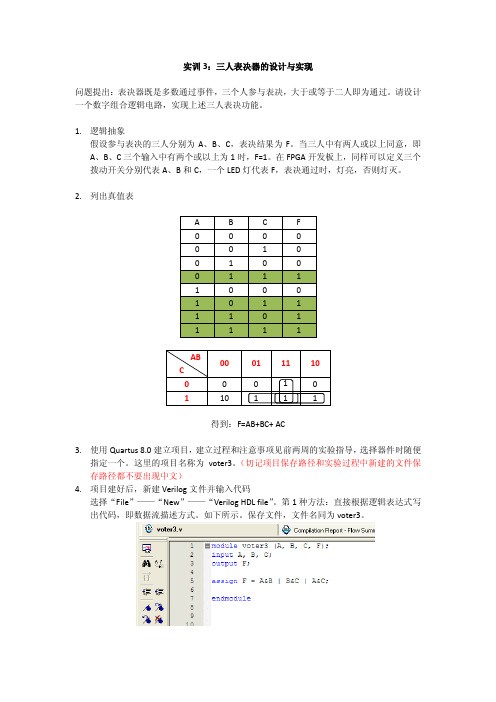
实训3:三人表决器的设计与实现问题提出:表决器既是多数通过事件,三个人参与表决,大于或等于二人即为通过。
请设计一个数字组合逻辑电路,实现上述三人表决功能。
1.逻辑抽象假设参与表决的三人分别为A、B、C,表决结果为F。
当三人中有两人或以上同意,即A、B、C三个输入中有两个或以上为1时,F=1。
在FPGA开发板上,同样可以定义三个拨动开关分别代表A、B和C,一个LED灯代表F,表决通过时,灯亮,否则灯灭。
2.列出真值表得到:F=AB+BC+ AC3.使用Quartus 8.0建立项目,建立过程和注意事项见前两周的实验指导,选择器件时随便指定一个。
这里的项目名称为voter3。
(切记项目保存路径和实验过程中新建的文件保存路径都不要出现中文)4.项目建好后,新建Verilog文件并输入代码选择“File”——“New”——“Verilog HDL file”。
第1种方法:直接根据逻辑表达式写出代码,即数据流描述方式。
如下所示。
保存文件,文件名同为voter3。
5.编译项目。
“Processing”——“Start Compilation”6.功能仿真编译通过后,新建波形仿真文件:“File”——“New”,选择“Vector Waveform File”,如下图所示:在出现的编辑界面左侧右键,选择如下:在“Insert Node or Bus”里选择“Node Finder…”在弹出来的“Node Finder”中,首先在“Filter”中选择“Pins:Unassigned”,然后点击“list”,在“Nodes Found”中会列出所有的引脚,第三步选择全部引脚(鼠标拉),点击“>>”,最后点击“OK”即可。
在回到的“Insert Node or Bus”界面点击“OK”。
这时候会看到所有的引脚会列出来,如下所示,三个输入默认为低电平,输出F状态未知。
由实验原理可知,为了得到A、B、C三个信号不同的组合,设置A为10ns周期信号,B为20ns周期信号,C为40ns周期信号。
- 1、下载文档前请自行甄别文档内容的完整性,平台不提供额外的编辑、内容补充、找答案等附加服务。
- 2、"仅部分预览"的文档,不可在线预览部分如存在完整性等问题,可反馈申请退款(可完整预览的文档不适用该条件!)。
- 3、如文档侵犯您的权益,请联系客服反馈,我们会尽快为您处理(人工客服工作时间:9:00-18:30)。
实验三
一、实验内容
用Verilog HDL语言编写二分频器电路模板,四分频器电路模块,八分频器电路模块,并编写测试模块仿真。
二、主要程序
1.电路模块:
moduletwo_div(clk1, clk2, clk4, clk8, rst);
output clk2, clk4, clk8;
reg clk2, clk4, clk8;
input clk1, rst;
always @(posedge clk1 or negedgerst)
begin
if(!rst)
begin
clk2 = 0; clk4 = 0; clk8 = 0;
end
else if(clk1)
begin
clk2 = ~clk2;
if(clk2)
begin
clk4 = ~clk4;
if(clk4)
clk8 = ~clk8;
end
end
end
endmodule
测试模块:
`timescale 1 ns/ 1 ns moduletwo_div_vlg_tst(); // constants
// general purpose registers regeachvec;
// test vector input registers reg clk1;
regrst;
wire clk2;
wire clk4;
wire clk8;
two_div i1 (
.clk1(clk1),
.clk2(clk2),
.clk4(clk4),
.clk8(clk8),
.rst(rst)
);
initial
begin
#1 rst = 1; clk1 = 0;
#1 rst = 0;
#1 rst = 1;
#500 $stop;
end
always
// optional sensitivity list
// @(event1 or event2 or .... eventn)
begin
// code executes for every event on sensitivity list
// insert code here --> begin
#10 clk1 = ~clk1;
// --> end
end
endmodule
三、仿真结果
四、实验小结
通过此次实验。
我在Modeisim软件平台上通过使用Verilog HDL语言编写信号的二分频、四分频、八分频电路。
通过编写二分频电路的基础。
把二分频电路再进行二分频。
使之得到八分频电路。
经过这次实验。
使我对Verilog有个更深刻的了解。
在编写程序的过程中。
Texebenech测试文件的编写十分重要。
因为软件并不能检测出测试文件的错误。
如果测试文件出错。
将无法得到仿真结果。
所以在编写测试文件时要小心谨慎。
