科技小制作说明书——《光影实验套件》
幼儿园优秀自制教具大赛制作使用说明:多功能光影剧场

自制玩教具说明文稿一、自制玩教具名称:多功能光影剧场二、自制玩教具图片三、活动目标1.预设认知目标幼儿通过欣赏及操作体验不同光影偶戏,感受光影游戏的有趣和奥秘,了解光源、戏偶、影幕三者之间的关系。
2. 预设能力目标幼儿自由地运用各种戏偶、材料和自己的肢体,与光影进行创意游戏,培养幼儿的艺术表现力、想象力和创造能力,以及幼儿的合作能力与审美能力。
3. 预设情感目标感受和体验传统偶戏与现代光影技术结合的魅力,热爱光影偶戏表演,传承和弘扬中国传统文化。
四、作品设计思路作品借助光沿直线传播及透光的科学原理。
当光线照射到物体时,就会被挡住,从而形成影子。
不同形状、不同颜色、不同材质物体的影子,形状和颜色也各不相同。
我们设计的这组作品正是利用这一原理来完成各种造型和场景的变化,幼儿通过对戏偶的简单操作,利用光源的投射,在影幕上呈现出变幻灵动的光影,从而达到形象生动,具有魔幻的表演。
五、制作材料和方法该作品基本结构由三部分组成:影幕、戏偶、光源。
1.影幕制作材料:白色影布、PVC管。
制作方法:先用PVC管制作出3块大小合适的影幕框架,再把白色影布缝制在PVC管上。
2.戏偶(1)杖头偶制作材料:泡沫球、木棍、丝袜、布、纸巾、橡皮筋及其它手工辅助材料。
制作方法:用一根木棍插入一个大泡沫球中心,再套上丝袜后在上面进行各种人物或动物造型,木棍上套上一块方形、大小合适的布或纸巾当身体,两侧再各用一根插好小泡沫球的木棍,分别用两边的布或纸巾包裹住泡沫球,再用橡皮筋扎紧当做戏偶的手,这样一个杖头偶就制作好了。
(2)纸偶制作材料:卡纸、小木棍。
制作方法:纸偶是用卡纸剪出或折出不同物体的造型,再把它们粘贴到木棍上进行操作。
(3)膜偶制作材料:各种材质和颜色的塑料膜、小木棍。
制作方法:膜偶是用塑料膜剪出不同物体的造型,可用彩色塑料膜直接剪出不同物体的造型,或者用透明膜剪出不同造型并加以装饰,再粘贴到木棍上进行操作。
3.光源:手电筒、充电移动投影仪。
小学科学教师自制教具

小学科学教师自制教具“太阳和一、教具名称:“太阳和影子” 三合一实验装置二、教材实验分析苏教版《科学》五年级(上册)第一单元“白天和黑夜”第一课“太阳和影子”一课,本课有三个活动,分别达到以下目的:1.认识一天中太阳在天空中的位置变化和高度变化;2.发现阳光下影子变化的规律,3.模拟太阳视运动过程中影子的变化,引导发现规律。
观察太阳在天空中高度时教材设计的是叠拳法,拳头数就是太阳的高度,叠拳法由于学生本身主观性和拳头大小的差异,实验结果不统一,误差比较大。
观察太阳的位置时原有教具是在底盘前端放一个指南针,指南针四周标明东、南、西、北方向,物体再放另一处,分隔开来,个人觉得不如把物体放在中心,四周注明东、南、西、北方向比较符合学生平常的认知经验,也比较形象直观,不管好生、差生一眼能看明白,真正面向全体学生。
观察阳光下物体影子的变化,实验目的是得出一天中,影子变化由长至短再至长,温度变化由低→高→低的的规律,教材设计2个活动,活动1.早晨,在校园里找一个物体,给它的影子做上记号。
下课的时候再去画一画。
由于场地不能专有,实验记录得不到保证,另外受到时间、课程设置的限制,实验并不顺利。
原有教具干脆没有活动1只测量影子的长度。
我认为活动1很重要,影子是随着时间变化的,每一节下课,把同一物体在阳光下的影子画下来,进行比较,更能直观的得出同一物体在阳光下的影子变化规律。
至于活动2.每到课间话画出白纸上铅笔影子,并在影子的顶端记下当时的温度和时间,完全可以在活动1的影子旁标上当时的温度和时间,合二为一!为了方便学生还可以集成电子表和温度计。
教材设计了模拟太阳运动过程中影子的变化实验,目的是得出太阳高度越高,影子越短;反之影子越长的规律,教材设计用手电筒代表太阳,竹篾代表太阳运动的轨迹,小标杆代表地球上能产生影子的物体。
实际是竹篾不容易找到,而且易变形,时间一长就发黄干枯,又不能重复使用。
所以我用四号钢筋弯成半圆状代替竹篾,不用铁丝是因为够粗才不易变形,可重复使用,手电筒也选择扁平的,尽量放大模拟的空间!为了方便教学,更简单易行的解决本课难点,结合生活实际,我把书上的三个活动整合成了“太阳和影子” 三合一实验装置。
小学科学实验装备 光影关系演示仪
光影关系演示仪
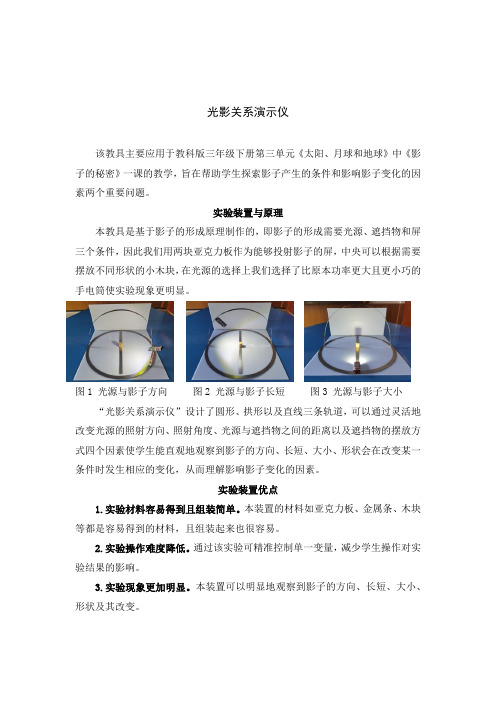
该教具主要应用于教科版三年级下册第三单元《太阳、月球和地球》中《影子的秘密》一课的教学,旨在帮助学生探索影子产生的条件和影响影子变化的因素两个重要问题。
实验装置与原理
本教具是基于影子的形成原理制作的,即影子的形成需要光源、遮挡物和屏三个条件,因此我们用两块亚克力板作为能够投射影子的屏,中央可以根据需要摆放不同形状的小木块,在光源的选择上我们选择了比原本功率更大且更小巧的手电筒使实验现象更明显。
图1 光源与影子方向图2 光源与影子长短图3 光源与影子大小“光影关系演示仪”设计了圆形、拱形以及直线三条轨道,可以通过灵活地改变光源的照射方向、照射角度、光源与遮挡物之间的距离以及遮挡物的摆放方式四个因素使学生能直观地观察到影子的方向、长短、大小、形状会在改变某一条件时发生相应的变化,从而理解影响影子变化的因素。
实验装置优点
1.实验材料容易得到且组装简单。
本装置的材料如亚克力板、金属条、木块等都是容易得到的材料,且组装起来也很容易。
2.实验操作难度降低。
通过该实验可精准控制单一变量,减少学生操作对实验结果的影响。
3.实验现象更加明显。
本装置可以明显地观察到影子的方向、长短、大小、形状及其改变。
用光影玩出不一样的花样——幼儿园大班科学活动教案

一、活动背景及目的在幼儿园日常活动中,科学活动是非常重要的一部分。
科学活动不仅可以提高幼儿在探究物理、化学、生物等方面的知识,更可以让幼儿锻炼观察能力、动手操作能力和逻辑思维能力。
本次活动的让幼儿通过利用光影的特性,亲手制作一些有趣的实验,旨在帮助幼儿更好地理解光的特性,并培养队合作和创新思维的能力。
二、活动过程1.实验一:画幅神秘的画材料:黑布、手电筒、不同颜色的丝带步骤:1)在黑布上贴上不同颜色的丝带,使其形成不同的图案;2)关闭教室门窗;3)利用手电筒照射丝带,形成不同的光影效果。
活动目的:通过实验一,让幼儿了解光的特性,知道黑色可以吸收光线而不反射,而丝带的颜色可以吸收或反射特定的光线颜色,在黑色布上产生不同颜色的光影效果。
同时,幼儿还能通过实验一锻炼动手能力和观察能力,创造出神秘有趣的画面。
2.实验二:形影相对材料:光源、不同物体、白色墙壁(或干净的白布悬挂在墙上)步骤:1)选择一个光源放在离物体3米左右的地方;2)把物品放在光源前方,与墙壁成50度角;3)把墙壁上的阴影轮廓画出来。
活动目的:通过实验二,幼儿可以了解到物体和光的关系,了解光线射向物体后,产生的影子是由物体挡住了光线而形成的。
同时,幼儿还能通过实验二锻炼观察力和动手能力。
3.实验三:做光束的屏障材料:手电筒、金属账夹步骤:1)打开手电筒,利用手电筒形成一个直的光束;2)拿起金属账夹,放在光束前方,并稍微倾斜账夹。
活动目的:通过实验三,让幼儿了解光的穿透性和反射性。
幼儿可以观察到光线因为金属账夹的阻挡而形成阴影,同时金属账夹也反射出光线。
同时,幼儿还能通过实验三锻炼动手能力和观察能力。
三、活动效果经过本次活动,幼儿们学习到了不同的光学概念,并亲身进行了一系列的实验。
他们通过观察到的神秘话影、形影相对以及光束屏障,锻炼了自己的观察能力、动手操作能力和创新思维能力。
通过团队合作和沟通,幼儿们不仅收获了知识,还培养了团队协作和合作精神。
葱花3D可控的实验小作品中的光说明书

Class 168/170/171Enhancement PackContentsHow to install (2)Liveries (3)Keyboard Controls (15)Features (16)Voith T211rzze Hydraulic Transmission (17)Adhesion (18)Cooling Fan Simulation (19)Automatic Unit Numbering (20)Dynamic Exhaust Effects (20)Player Changeable Destination Display (21)Bits and Bobs (24)Setting Up the Driver’s Cab (25)Scenarios (25)Credits (25)How to Install1)Locate where you have downloaded this pack and unzip it. Information onhow to do this can be found here.2)Go to the location where you have extracted the files from the .zip file.3)Now find the .exe file called ‘Class 168-170-171 Enhancement Pack’. Double-click this file.4)Follow the steps and by the end of the process, the main part of this pack willhave installed.5)If you intend to use any of the included scenarios, make sure you have thefreely available extra stock pack and requirements installed, as listed on theproduct page.6)To ensure the cab environment sounds as intended in this pack, please makesure that ‘EFX’ is ticked within your in-game Audio settings.LiveriesClass 168Chiltern Railways - CR APChiltern Railways (Mainline) - CR (M) APClass 170Anglia Railways - AR APAnglia Railways (Revised) - AR Rev APONE - ONE APONE Dark - ONE Dark APEx-Anglia Railways (Revised) (NXEA/AGA/GA/GA2) -Ex-AR Rev (NXEA/AGA/GA/GA2) APEx-ONE (NXEA/AGA/GA/GA2) - Ex-ONE (NXEA/AGA/GA/GA2) APEx-ONE Dark (NXEA/AGA/GA) - Ex-ONE Dark (NXEA/AGA/GA) APGreater Anglia - GA APMidland Mainline - MML APEx-Midland Mainline (Central Trains/CrossCountry) - Ex-MML (CT/XC) APCentral Trains - CT APCrossCountry - XC APLondon Midland - LM APSouth West Trains - SWT APHull Trains - HT APFirst Transpennine Express - FTPE APScotRail - SR APFirst ScotRail - FSR APSPT Rail - SPT Rail APScotRail Saltire - SR Salt APClass 171Southern - SN APKeyboard ControlsNon-standard keyboard controls are listed below:L - Cab light ON/OFFE - Deadman’s pedal (DVD reset)F7 - Destination blind UPF8 - Destination blind DOWNY - Driver reminder appliance (DRA) ON/OFFC - Driver to guard buzzerCtrl+D - Driver vigilance device (DVD) ON/OFFZ - Engine start buttonCtrl+Z - Engine stop button+ - Hill start buttonShift+W - Master key IN/OUTK - Tail lights switch ON/OFFV - Wiper switch CLOCKWISEShift+V - Wiper switch ANTI-CLOCKWISEFeatures•23 liveries•Higher resolution cab visuals•Detailed internal & external audio•Accurate acceleration & braking physics •Voith T211rzze hydraulic transmission•Adhesion•Cooling fan simulation•Automatic unit numbering•Dynamic exhaust effects•Player changeable destination display•Driver vigilance device (DVD)•Bits and BobsVoith T211rzze Hydraulic TransmissionGreat care has been taken in recreating the characteristics of the 2-stage hydraulic transmission used in this unit.1st Stage - Torque ConverterWhen accelerating from a standing start, oil fills the torque converter and the engine revs up, which allows acceleration to take place. Unlike the Class 15x family of units, the engine does not rev up until the oil has filled the converter, hence the lack of an initial surge of rpm before settling and a smooth increase in rpm instead. As a result, there is a 3 second delay between applying power and the engine responding. During this 1st stage, engine rpm is directly controlled via the notch selected on the power handle.2nd Stage - Fluid CouplingAt 70mph, the oil transfers from the torque converter to the fluid coupling which results in a reduction of engine rpm. During this stage, engine rpm is directly proportional to the speed of the train which means rpm will be the same regardless of which notch is selected on the power handle. All that varies is the load being placed on the engine. As speed increases then, you will gradually hear engine rpm rise in sync.The unit will stay in this second stage until speed drops below 66mph. At this point, the transmission reverts to the first stage.AdhesionAdhesion between a train’s wheels and the rails plays a big part in allowing a train to accelerate or brake. Too little of it and the train will slip or slide. There are a myriad of factors that control the level of adhesion and we have attempted to simulate the most important of these to give a varied and realistic driving experience: SeasonAdhesion is generally good in dry conditions during summer and spring. Slightly decreased adhesion during winter to take account of the increased amount of moisture and possible ice on the rails due to cooler temperatures. Much decreased adhesion during autumn due to leaf mulch.WeatherAdhesion decreases in wet weather, especially so when rain first starts falling before it has had a chance to clean the railhead. If rain is light, it will take longer for the railhead to be cleaned whereas heavy rain will clean it quicker, resulting in adhesion recovering sooner.When using the drizzle weather pattern in our Sky & Weather Enhancement Pack, adhesion is particularly poor as the rain hasn’t enough force to clean the railhead but still makes it sufficiently wet to worsen adhesion.Time of DayAdhesion will decrease somewhat after dusk as the air cools and dew is more likely to form on the railhead. This persists throughout the night until around an hour after sunrise when higher temperatures or the sun dry it out. In our simulation, this factor is reduced during summer to account for warmer temperatures, which on average result in less dew.TunnelsWhen adhesion is poor due to external factors such as weather or season, adhesion will generally improve upon entering a tunnel, which is not as susceptible to these factors. When adhesion is good during dry weather and outside of autumn, adhesion may decrease a little upon entering a tunnel due to their damp nature.WheelslipWheelslip protection aids the driver when powering or braking during times of poor adhesion.When wheelslip is encountered during acceleration, a two stage process takes place:1)Power is automatically reduced and the ‘WSP Activity’ light flashes in the cab.2)Once wheelslip stops, power is reapplied to the notch selected on thecombined power handle and the ‘WSP Activity’ light extinguishes. If wheelslip reoccurs, the process starts again.As a driver, you must assess which power notch is most suitable for the conditions and balance the occurrence of wheelslip with the maximum possible rate of acceleration.WheelslideWhen wheelslide is encountered during braking, a two stage process takes place:1)Brake pressure is automatically reduced and the ‘WSP Activity’ light flashes inthe cab.2)Once the wheelslide stops, brake pressure is returned to the notch selected onthe combined power handle and the ‘WSP Activity’ light extinguishes. Ifwheelslide reoccurs, the process starts again.As a driver, you must resist the temptation to reduce the brake yourself as the wheelslip protection will offer the best braking performance.Cooling Fan SimulationThe distinctive cooling fan on these units has been simulated and is audible on the outside on the train. How quickly the engine’s temperature rises and how efficient the fan is at cooling it, primarily depends on the season but also on how hard the engine is being driven. For example, in the summer and with a lot of high speed running, you can expect it to be active a lot of the time. In contrast, during cooler months and with low speed running, it won’t be active as much, especially in winter. On top of this, to reflect the variable nature of each engine and its efficiency at cooling, each engine is given a random efficiency rating at the start of a scenario, just to provide even more variation.Automatic Unit NumberingWhen placing a unit in the scenario editor or using one in Quick Drive, all vehicles will automatically be given correct unit and coach numbers instead of you having to select each vehicle and changing their number manually so they match. The unit number is usually controlled via the DMSL coach (this can vary depending on the particular formation of your chosen livery) if you wish to change it. Please note that the destination display on both driving coaches is also controlled via this coach. Dynamic Exhaust EffectsDynamic exhaust effects mean that the exhaust reacts to what the engine is doing. For example, when in notch 7, the engine will produce more exhaust than it would when idling. Also, when revving up, exhaust thickens before thinning out when rpm settles. Equally, when revving down, exhaust thins. On top of that, when starting up, exhaust rises in sync with the sound of the engine revving up. Finally, in reality, the smokiness of each vehicle varies depending on how well maintained it is, so to represent this in the simulator, a random ‘clag’ factor is allocated to each vehicle which ranges from 1 to 10; 1 being the cleanest and 10 being the dirtiest.Player Changeable Destination DisplayThe destination display can be changed during a scenario by pressing either the F7 or F8 keys. For each livery, a set of relevant destinations are provided. Please see below for a list of the available destinations on each livery and their relevant code if you wish to use them v ia the unit’s number on an AI service:Anglia Railways / Anglia Railways (Revised) / ONE / ONE Dark /Bits and BobsThis section is dedicated to aspects of this pack that don’t warrant a dedicated section but are still of note:•The reverser must be placed in ‘Neutral’ to start the engine.•If the emergency brake applies, power can only be regained if the power handle is returned to ‘Off’.• 1 second delay between train passing over AWS magnet and AWS warning sound occurring. The F3/F4 HUD will show the warning immediately so you must wait 1 second before trying to cancel it.•The headlights only provide illumination before sunrise and after sunset. This is to avoid the unrealistic appearance of projected light in broad daylight.•If speed rises above 103mph, power will be cut until speed falls below 97mph and the combined power handle is placed in the ‘Off/Release’ position.•When the doors are open, full brake pressure is applied and the ‘Door Interlock Lost’ indicator light illuminates.•Notched combined power handle; 7 power notches & 4 brake notches. •Intermittent, slow and fast setting added to windscreen wiper.•Separate engine start & stop buttons now operational. Engine stop button illuminates when engine is stopped.•Master key & 4-step reverser (Off/Reverse/Neutral/Forward).•Cab light.•‘Hill start’ button which applies step 1 brake pressure below 3mph.•Functioning ‘Train Fault’ & ‘No Train Fault’ indicator lights when changing reverser position.•‘Door power’ indicator light which illuminates when speed falls below 3mph and extinguishes when speed rises above 10mph.•Digital clock below speedometer.•Individually controlled headlights & tail lights with proving lights in the cab. •Detailed headlight, marker light & tail light textures for both new and old styles. •Improved appearance of Driver Reminder Appliance (DRA).•Cab camera angle amended so more of the desk is visible.•‘Max Speed 100mph’ label added to driver’s side of cab.Setting Up the D river’s CabPlease follow these steps to set up the cab so you are ready to move:1)Turn the master key in by pressing Shift+W.2)Move the reverser to the ‘neutral’ position by pressing S.3)Cancel the AWS self-test alarm by pressing Q.4)Turn off the tail lights by pressing K.5)Turn the headlights on by pressing H.6)Turn the Driver Reminder Appliance (DRA) off by pressing Y. ScenariosAPC170EP: 06:45 Lowestoft - London Liverpool StreetRoute = GEML London - IpswichTrack covered = Ipswich - London Liverpool StreetTraction = ONE 170205 & 170207Year = 2005Duration = 1 hour 15 minutesAPC170EP: 08:26 Basingstoke - ColchesterRoute = GEML London - IpswichTrack covered = Stratford - ColchesterTraction = Anglia Railways 170206Year = 2000Duration = 55 minutesAPC170EP: Felixstowe ShuttleRoute = GEML London - IpswichTrack covered = Ipswich - Felixstowe - IpswichTraction = Greater Anglia 170270Year = 2017Duration = 55 minutesCreditsNicolas Schichan - Advanced scriptingDuncan Sealey & London Midland - Assistance in recording sounds Matt Valentine - Assistance in providing photos of the cab。
光影魔术秀

光影魔术秀作者:陈航来源:《课堂内外(小学版)》2018年第07期夏天,阳光灿烂得让人睁不开眼。
今天小雨突然看到阳台上有一些漂亮的彩色光,时不时闪现。
难道是有外星人?爸爸让他仔细看,其实是因为阳台上有一个小小的水晶摆件,彩色光是通过水晶反射形成的。
听起来好像很有趣,爸爸带小雨做了一个简单的小实验,立刻重现了美丽的彩色光。
水三棱镜准备材料一碗水和一个镜子这个小实验相信大家都很熟悉,非常简单,只要把镜子斜着插入装水的碗中,让镜子对着太阳直射的方向就可以了。
调节角度,很快你就会在周围的墙上看到一条彩色的光带啦。
为什么会这样三棱镜是色散棱镜的一种,能将太阳光分解成各种颜色的光。
当阳光透过水射到镜子上,被镜子反射时,光线就会通过镜子与水面形成的三棱水柱。
这个三棱水柱能起到三棱镜的作用,将阳光分解成多种颜色’所以我们就看到了漂亮的彩色光带。
星空手电筒准备材料手电筒、铝箔纸、缝衣针、剪刀、笔和纸白天可以玩阳光,晚上玩什么呢?小雨听爸爸妈妈说,他们小时候的夏夜,一家人经常到户外去乘凉,看满天的星星。
爸爸说,他用一把手电筒就能让小雨看到星星。
不信,试试看……1.拧开手电筒的前盖,取出镜片,在铝箔纸上剪出镜片轮廓。
2.在铝箔纸下面垫纸以免弄伤桌面,用针扎几个小孔。
3.将扎了孔的铝箔纸圆片夹在前盖与镜片之间,将前盖装回手电简,并拧紧。
这样就完成了。
4.在一个黑暗的房间,打开手电筒的开关,光线会从一个个小孔中射出。
这些光线投射到墙上就变成了一颗颗“星星”。
为什么会这样铝箔纸在这里的作用很简单,就是让手电筒的光线只通过我们戳了小孔的地方出来,变成星星点点的感觉,模拟星光。
妈妈有时候会用铝箔纸把食物包裹起来,放进烤箱。
铝箔纸似乎有神奇的功能,会让普通的食物变得很美味。
这是因为铝箔纸能够保护食物的水分不会流失太快,还可以帮助热力均匀分散,让食物不会因为热力太集中而煳掉。
所以,用铝箔纸包裹做出来的食物会特别好吃。
鞋盒投影仪爸爸妈妈说,他们小时候的夏天,除了有满天星星,还常常能看到露天电影。
3B科学激光光学实验试验套件说明书

Instruction sheet3B SCIENTIFIC ® PHYSICSLaser Optics Demonstration Set 1003049 Laser Optics Supplement Set 1003050®06/18 ALFTable of contentsSet To UseNo. of Exp.ExperimentPage Introduction1Tables of the settlements21003049/50Reflection on planar mirror E131003050Reflection on two planar mirrors E231003049Reflection of light rays on concave mirror – rays are parallel to optical axis E3a 3Reflection of light rays on concave mirror – rays are non-parallelE3b 41003049to optical axis1003049Reflection of light rays on convex mirror – rays are parallel to optical axis E4a 4Reflection of light rays on convex mirror – rays are non-parallelE4b 41003049to optical axis1003049Refraction of light passing air-glass boundary E5a 51003050Apparent depth of objects E5b 51003049Refraction of light passing glass-air boundary E6a 51003049/50Refraction on glass prism edge E6b 61003049Critical angle, total reflection E6c 61003049Total reflection – propagating of light in optical fibres E6d 61003049/50Light ray shift by glass planparallel plate E771003050Light ray shift by air planparallel plate E871003049/50Glass prism deviation of light ray E9a 71003049/50Glass prism minimal deviation E9b 81003050Air prism deviation of light E10a 81003050Air prism minimal deviation E10b 81003050Reflection of light on one edge of glass prism E11a 91003050Reflection of light on two edges of glass prism E11b 91003050Reflection of light on two glass prisms E11c 91003050Reflection of light on two glass prisms E11d 101003050Reflection of light on two glass prisms E11e 101003050Reflection of light on air prisms E12101003050Light ray passing a convex air-glass boundary E13a 111003050Light beam passing through convex air-glass boundary E13b 111003050Light ray passing through concave air-glass boundary E14a 111003050Light beam passing through concave air-glass boundary E14b 121003050Light ray passing through convex glass-air boundary E15a 121003050Light beam passing through the glass-air boundary E15b 121003050Light ray tracing passing concave glass-air boundary E16a 131003050Light beam passing through concave glass-air boundary E16b 13Light beam passing through glass convex lens - beam is parallelE17a 131003049/50to the optical axisLight beam passing through glass convex lens – the rays are non-parallelE17b 141003049/50to the optical axis1003050Light beam passing through thick glass convex lens E17c 14Light beam passing through glass concave lens – the rays are parallelE18a 141003049/50to the optical axisLight beam passing through glass concave lens – the rays are non-parallel E18b151003049/50 to the optical axisLight beam passing through air convex lens – the rays are parallelE19a151003050 to the optical axisLight beam passing through air convex lens – the rays are non-parallelE19b151003050 to the optical axisLight beam passing through air concave lens – the rays are parallelE20a161003050 to the optical axisLight beam passing through air concave lens – the rays are non-parallel E20b161003050 to the optical axis1003049/50 Parameters of thick lenses – determination of radius of curvatureE21a161003049/50 Parameters of thick lenses – focal lengthE21b171003049 Model of a normal eyeE22a171003049 Model of short-sighted eyeE22b171003049 Model of long-sighted eyeE22c181003049/50 Correction of spherical aberration by reducing the beam diameterE23a181003049 Correction of spherical aberration by combination of lensesE23b181003049 Keplerian telescopeE24a191003049 Galileian telescopeE24b191003049 CameraE25191003049Laser Optics Demonstration Set1003050Laser Optics Supplement SetThe column "SET TO USE" informs you which set is appropriate for which experiment (either 1003049, or 1003050 or both).IntroductionThe demonstration set 1003049 was designed for easy and clear demonstration of basic optical effects and devices. Using diode laser as a light source for experi ments enables both teacher and student to understand the principle of simple and more complicated optical systems. In this guide book you can find many basic experiments and demonstrations using 1003049 and 1003050 which is an additional set of optical elements containing air lenses, air prisms etc. Every experiment in this book has three parts:1. A simple description of the experiment2. A geometric diagram of the experiment3. A diagram showing what the experimentlooks like when it is set up.Shown in brackets under the title of the experiment is whether it can be demonstrated with the 1003049 or 1003050 set, or both. The same note can be find also in the table of contents in the last row. It is clear now, that some experiments cannot be done with 1003049 and some of them with 1003050.A very important constituent of the experiments is the LASER RAY BOX which consists of five laser diodes. Be careful to avoid direct eye contact with the laser beam! If you have basic set 1003049 and you are interested in realizing experiments for additional set 1003050, please,contact your distributor of didactic aids.Table of set elementsLaser Optics Demonstration Set 10030491Biconcave lensBiconvex lens2Biconvex lens3Biconvex lens4Biconvex lens5Small planeconcave lens6Large planeconvex lens7Small planeconvex lens89Concave mirror10Convex mirror11Planar mirror12Planparallel plate13Prism14Optical fibreWorking sheetsA Human Eye ModelB CameraGalileian TelescopeCKeplerian TelescopeDCorrection of Spherical AberrationEHartle's circleFSupplement Set 100305021Biconcave air lens22Biconcave glass lens23Biconvex air lens24Biconvex glass lens25Optical air prism26Equilateral optical glass prism27Rectangular optical glass prism (2 pc)28Square glass planparallel plate29Rectangular glass planparallel plate (2 pc) 11Planar mirror (2 pc)E1Reflraction on planar mirror(1003049/50)The law of reflection is demonstrated. When a light ray impinges a plane mirror under an angle α it is re-flected under the same angle ßα = ßBoth angles are measured from the perpendicular lineto the mirror plane.E2Reflection on two planar mirrors(1003050)An interesting relation can be shown:δ= 2γwhere δis the angle between the incident and the reflected ray and γis the angle between the mirrors'planes.E3a Reflection of light rays on concave mirror –rays are parallel to optical axis (1003049)The focal length f of the concave mirror is determined by the length of the line VF. The curvature radius can be obtained using the known formula:f r =2The distance of the centre of curvature S is twice aslong as the distance of the focus F.E3b Reflection of light rays on concave mirror –rays are non-parallel to optical axis (1003049)The axis ϕwhich is perpendicular to the optical axis and passes through the focus is referred as the focal plane of the concave mirror. If the parallel rays im-pinge the mirror, they meet at one point of the axis ϕafter the reflection. In the case of the rays parallel to the optical axis, the point belongs to the axis and iscalled the focus (F).E4a Reflection of light rays on convex mirror –rays are parallel to optical axis (1003049)The reflected rays, parallel to the optical axis, appear to start from one point on the right side behind the mirror. This point is referred to as the figure focus. The length of line VF determines the focal length f of the mirror. The radius of curvature can be obtained from the next formula.f r =2The distance of the centre of curvature S is two timeslonger than the distance of the focus F.E4b Reflection of light rays on convex mirror –rays are non-parallel to optical axis (1003049)The axis ϕwhich is perpendicular to the optical axis and passes through the focus is referred to as the focal plane of the convex mirror. If parallel rays impinge the mirror, they are scattered in such a way that they appear to start from one point of the plane ϕ. In the case of incidence rays parallel to the optical axis thispoint belongs to the axis.E5a Refraction of light passing air-glass boundary(1003049,transparency F)If light passes through one optical medium character-ized by refraction index n 1into the other with refrac-tion index n 2its direction is changed by Snell’s law:n sin α=n sin ß12where αis an incidence angle in the medium n 1and ß is an angle of refraction in the medium n 2. The anglesare measured from the normal to the planar boundary.E5b Apparent depth of objects(1003050)You can build up the model of observing the depth ofobjects in water or glass from air.Air AcrylicPencilAcrylicAirE6a Refraction of light passing glass-air boundary(1003049,transparency F)The ray is refracted with the refraction angle ß, which is larger than α. The ray is bent away from the normal.E6b Refraction on glass prism edge(1003049/50)When light passes through glass to air, Snell’s law can be written in the next form:n sin α= sin ß1Refractive index of air n = 1.2E6c Critical angle, total reflection(1003049, transparency F)The larger the incidence angle the larger the refrac-tion angle. If n 1<n 2a critical angle αexists. In other words, the refracted ray lies on the border of two me-diums. When the incidence angle is larger than the critical angle, there is no more refracted light and alllight energy is reflected, this is called total reflection.E6d Total reflection – propagating of light inoptical fibres (1003049)If light enters the optical fibre under some angles it propagates in it using the total reflection on the bor-ders of the fibre. An important parameter determines what angle should not be overcome. This parameter is called the numerical aperture. It is SIN of the maxi-mum entrance angle of the light. Also the minimal radius of the fibre bent is set by this parameter. Itcannot be smaller, when the fibre is installed.E7Light ray shift by glass planparallel plate(1003049/50)If a light ray passes through a planparallel plate its direction is not changed. The outgoing ray is shifted in accordance with the incoming one. The shift d can be estimated with respect to the thickness h of the plate using the formula:d h=−)(sin cos αββAcrylic AcrylicAirAcrylic AcrylicAirE8Light ray shift by air planparallel plate(1003050)In this case, a shift between the incoming and the out-going ray can be observed. This shift has an oppositedirection than in the case of the glass plate.E9a Glass prism deviation of light ray(1003049/50)If the prism is glass, after the light impinges the point A, it is bent toward the normal and refracts to point B.At this point it is bent into the air away from the nor-mal. The sum of all refraction angles is the deviationangle δ. It is the angle between the incidence and theoutgoing ray.E9b Glass prism minimal deviation(1003049/50)It can be seen that in the case of minimal deviation δmin the incidence angle αis equal to the angle of the outgoing ray ß. The direction of the refraction of light in the prism is parallel to the edge the ray does not pass through. The refractive index of the prism obeys the formula:Air AcrylicAcrylic AcrylicAirAcrylicAcrylicAirAirn =+sin sin 2min ϕδϕ2E10a Air prism deviation of light(1003050)Light passes through the glass-air border at point A.Then it is directed away from the normal axis and af-ter light passes through point B, it is then directed to-ward the normal. The sum of the refraction angles is referred as the deviation angle δ. It is the angle be-tween the incidence and the outgoing ray.E10b Air prism minimal deviation(1003050)In the case of minimal deviation δthe incidence min,angle αis equal to the angle of the outgoing ray ß. The direction of the refracted light in the prism is parallel to the edge the ray does not pass through. The refrac-tive index of the prism obey formula (see E9b). The deviation has an opposite direction as in the case of aglass prism.E11a Reflection of light on one edge of glass prism(1003050)When the rays impinge the edge, they are totally re-flected. If the prism is slightly adjusted reflection andrefraction can be observed.E11b Reflection of light on two edges of glassprism (1003050)The conditions for total reflections are fulfilled on both edges of the prism. If the top ray of the incidence light is eliminated, the bottom ray of the outgoing lightdisappears. The picture is 180° rotated.AcrylicAirAirAirAirAcrylicAcrylic AcrylicE11c Reflection of light on two glass prisms(1003050)Conditions for total reflection are fulfilled on everyedge. E11d Reflection of light on two glass prisms(1003050)Conditions necessary for total reflection are fulfilledon every edge.E11e Reflection of light on two glass prisms(1003050)Conditions necessary for total reflection are fulfilledon every edge.E12Reflection of light on air prism(1003050)If the incidence angle of light to the edge of the prism (25) is smaller than critical angle (42°), the rays are reflected into the glass. If the angle is greater, a part ofthe light passes through the air prism.AirAirAcrylicAcrylic(1003050)When a ray impinges the air-glass boundary at point A, it is directed toward the normal. The normal is de-fined as the line from point A to the centre of bound-ary curvature S.E13b Light beam passing through convex air-glassboundary (1003050)Using a boundary of convenient curvature radius and an auxiliary glass element, where the rays are refracted,one can observe that the rays are met at the point F' inthe optical axis – figure focus.boundary (1003050)When a ray impinges the boundary at point A, refrac-tion towards the normal is observed. The normal is defined as the line from point A to the centre of bound-ary curvature S.E14b Light beam passing through concave air-glassboundary (1003050)The beam after passing the boundary is divergent.Elongating the refracted light to the other side one can find a point on the optical axis where the line meets. Itis figure focus F'.Acrylic AirAirAcrylicAcrylicAcrylicboundary (1003050)When a ray impinges the boundary at point A, refrac-tion away from the normal is observed. The normal can be defined as the line from point A to the centre ofboundary curvature S.E15b Light beam passing through convex glass-airboundary (1003050)The beam after passing the boundary is divergent. Elon-gating the refracted light to the other side one can find a point on the optical axis where the line meets. It isfigure focus F'.boundary (1003050)When a ray impinges the boundary at point A, refrac-tion away from the normal is observed. The normal is defined as the line from point A to the centre of bound-ary curvature S.E16b Light beam passing through concave glass-airboundary (1003050)The beam is convergent after passing the boundary.Parallel rays meet in one point of the optical axis –figure focus F'.AirAirAcrylicAcrylicAcrylicAcrylicE17a Light beam passing through glass convex lens– beam is parallel to the optical axis (1003049/50)A convex glass lens behaves as a convergent optical system and the rays meet at figure focus F' after pass-ing through the lens.E17b Light beam passing through glass convex lens– the rays are non-parallel to the optical axis (1003049/50)The plane ϕ' which is perpendicular to the optical axis,combined with the figure focus F' is called a figure fo-cus plane. If a beam of perpendicular rays impinges the convex glass lens, the rays cross the plane ϕ' atone point.E17c Light beam passing through thick glassconvex lens (1003050)By inserting planparallel plates into the space between two elements (23), a model of a thick lens can be con-structed. The thickness d of the lens can be changed.If the thickness increases the focal length of the lens decreases. For a critical thickness the lens changes fromconvergent to divergent.E18a Light beam passing through glass concavelens – the rays are parallel to the optical axis (1003049/50)The rays are divergent after passing a concave glass lens, they do not create a real figure. By elongating the rays it is seen that the lines have a common intersec-tion – figure focus F'.AirAcrylicAcrylicAcrylicAcrylicE18b Light beam passing through glass concavelens – the rays are non-parallel to the optical axis(1003049/50)The plane ϕ' which is perpendicular to the optical axis,combined with the figure focus F' is called a figure focus plane. If a beam of perpendicular rays impinges the concave glass lens, the elongated lines of the rays cross the plane ϕ' at one point.E19a Light beam passing through air convex lens –the rays are parallel to the optical axis (1003050)The rays are divergent after passing a convex air lens,they do not create a real figure. By elongating the rays one can see the lines has a common intersection –figure focus F'.E19b Light beam passing through air convex lens –the rays are non-parallel to the optical axis (1003050)The plane ϕ' which is perpendicular to the optical axis,combined with the figure focus F' is called a figure focus plane. If a beam of perpendicular rays impinges the convex air lens, the elongated lines of the rays cross the plane ϕ' at one point.E20a Light beam passing through air concave lens– the rays are parallel to the optical axis (1003050)A concave air lens behaves as a convergent optical sys-tem and the rays meet at figure focus F' after passingthrough the lens.AirAirAirAirAirAcrylicAcrylicAcrylicAcrylicE20b Light beam passing through air concave lens– the rays are non-parallel to the optical axis (1003050)The plane ϕ' which is perpendicular to the optical axis,combined with figure focus F' is called a figure focus plane. If a beam of perpendicular rays impinges the concave air lens, the rays cross the plane ϕ' at one point.E21a Parameters of thick lenses – determinationof radius of curvature (1003049/50)The lenses in the set have cylindrical refraction sur-faces with circular bottoms with equal radia of curva-ture. You can measure these radii by using a milimetregrid.E21b Parameters of thick lenses – focal length(1003049/50)In the case of a thick lens (a lens with not negligible thickness) the definition of the focal length as a dis-tance of the focus from the main planes (points – Hand H'), must be taken into account.E22a Model of a normal eye(1003049, transparency A)Display rays parallel to the optical axis intersect after passing through uncorrected eye lens at one point of the retina.Place the eye lens (1) directly behind the line O 2.AcrylicAcrylicRetinaEye lensAirAirE22b Model of short-sighted eye(1003049, transparency A)Display rays parallel to the optical axis intersect after passing through uncorrected eye lens at one point of the optical axis before the retina.Place the eye lens (2) directly behind the line O 2and the correction lens (5) between the lines O 1and O 2.E22c Model of long-sighted eye(1003049, transparency A)Display rays parallel to the optical axis intersect after passing through uncorrected eye lens at one point of the optical axis after the retina. A correction lens must be convergent. The focal length f ' of the system of eye lens and the correction lens is:f f f f f ’’’’’=+2121where f 1' is the focal length of the eye lens and f 2' isthe focal length of the correction lens.E23a Correction of spherical aberration byreducing the beam diameter (1003049/50)Spherical aberration of a lens can be reduced by re-ducing the diameter of the beam which impinges the lens. The rays which are far away from the optical axismust be obscured.E23b Correction of spherical aberration bycombination of lenses (1003049, transparency E)The spherical aberrations of divergent and convergent lenses have an inverse effect. By a convenient combination of these two types of lenses the aberra-tion can be corrected. The aberration ∆f =f 1–f 2is defined as the difference between the focal length f 1of marginal beam rays and the focal length f 2of paraxial rays. In the case of a convergent lens the aberration is of a plus sign and for a divergent lens it is a minus sign.RetinaEye lensEye lensRetinaCorrection lens (5)Correction lens (4),(between O 1 and O 2)E24a Keplerian telescope(1003049, transparency D)The figure from Kepler's telescope is reversed. This can be verified by obscuring a marginal ray. One can see that if the top ray is obscured, in the output ray the bottom ray disappears. The figure is unreal andmagnified.E24b Galileian telescope(1003049, transparency C)In this experiment the incident angle can be changed.The larger change of the output angle is observed (the viewing angle is magnified – the figure is magnified).The figure is created by parallel rays, so it is unreal and magnified. If the top ray of the incident beam isobscured, the top ray of the output beam disappears.E25Camera(1003049, transparency B)The lens of the camera is a convergent optical system.The figure which appears on the rear part of the cam-era is real and reversed. It is directed onto the opticalmaterial.ObjectiveOcularObjectiveOcular。
自制光影小实验教程作文

自制光影小实验教程作文
哎,伙计们,今儿个给大伙儿介绍个好玩嘅玩意儿——自制光影小实验。
咱们用嘅都是家里头常见嘅物件儿,简单易行,还特别有趣儿。
首先,咱们得准备点啥呢?嗬,不复杂,就这几样儿:
1. 一个鞋盒或者差不多大小嘅纸盒子。
2. 一块白布或者白纸,能铺满盒子嘅底部。
3. 一个小手电筒或者手机嘅闪光灯。
4. 一些剪纸,可以是星星、月亮、心形,啥形状都行。
5. 胶带或者订书机。
接下来,咱们就开始动手吧:
1. 先把白布或者白纸铺在盒子嘅底部,这样儿投影嘅时候能更亮堂。
2. 用胶带或者订书机把盒子嘅顶部或者侧面开一个小窗口,大小能把手电筒或者手机嘅闪光灯伸进去就行。
3. 然后,把剪纸贴在盒子嘅另一侧,记得要贴嘅密实点,这样投影嘅效果才会更好。
4. 一切准备就绪,就可以把灯关了,把手电筒或者手机嘅闪光灯
伸进之前开嘅小窗口里头,对着盒子嘅内侧。
5. 最后,慢慢转动手电筒或者手机,调整角度,就能看到盒子里
头嘅白布上出现各种各样嘅光影图案啦!
这玩意儿不光能自个儿玩,还能叫上小伙伴儿一起,或者给家里
嘅小孩子们展示,他们肯定喜欢。
光影嘅变化能激发孩子们嘅想象力,还能让他们对科学产生兴趣。
行啦,今儿个就说到这儿,赶紧动手试试吧,保证你玩得不亦乐乎!。
制作光的实验器材科学活动《光》教案

制作光的实验器材科学活动《光》教案教案光是我们日常生活中必不可少的元素,我们可以在太阳照耀下享受温暖的阳光,我们可以在黑暗中使用灯光照亮房间,我们可以看到各种颜色的物体。
然而,你知道光是如何产生的吗?你知道光是如何传播的吗?在本次实验中,我们将探究光是如何产生的,并制作简单的实验器材,帮助我们更好地理解光,这就是科学活动《光》教案。
实验1:用塑料球制作简单的实验器材材料:透明的塑料球、小灯泡、电线、电池、剪刀。
步骤:1.在塑料球上面用剪刀剪出一个小孔2.将小灯泡与电线连接,然后接上电池。
3.将灯泡和电线放入小孔中,并将其固定。
结果:当电流通过灯泡时,灯泡会亮起来,从而发出光线。
透过塑料球可以看到灯泡发出的光线沿着球体散开。
实验2:用简单的物品制作放大镜材料:塑料球、胶带、剪刀、水。
步骤:1.将塑料球切成两半。
2.在其中一个半身上涂上水。
3.然后将两个半球对接固定,使涂有水的一面朝向内部。
结果:由于水具有放大的作用,将水填充在塑料球中,然后将光线通过放大镜,可以发现物体的图像被放大了。
实验3:利用半反射镜制作实验器材材料:镜子、透明的塑料球、胶带、剪刀。
步骤:1.将表面透明的塑料球切成两半。
2.在一个半球面上粘上一个小半球的镜子。
3.将两个半球对接粘合起来。
结果:当将光线从半透明的面射向半反射镜时,光线将分成两部分,一部分被反射回来,另一部分穿透玻璃。
这意味着可以将光通过这样的实验器材分离成两个方向,并将光拆分成不同的波长。
实验4:制作简单的光谱仪材料:黑纸、白卡纸、剪刀、定位用的针。
步骤:1.将黑纸剪成一个长条形状。
2.在白卡纸上画一条直线,并将其固定在黑纸的边缘上。
3.使用针在白卡纸上固定出一些小孔。
结果:当将光线从光源射在白卡纸上,光穿过小孔并经过黑纸的时候,光就会被分成不同的波长,形成光谱。
可以看到由红到紫的所有颜色。
结论:通过上述实验,我们可以更深入地了解光线的行为和特性,并制作出简单的实验器材。
光影科学实验报告

一、实验背景光影现象是自然界中普遍存在的现象,它是光在传播过程中遇到物体阻挡而产生的。
为了探究光影现象,我们进行了以下实验。
二、实验目的1. 观察光影现象,了解光在传播过程中的特性。
2. 探究光在直线传播过程中遇到不同物体时的变化。
3. 通过实验,培养学生的观察能力和动手操作能力。
三、实验器材1. 透明塑料板2. 白纸3. 激光笔4. 小木棒5. 量角器6. 记录本四、实验步骤1. 将透明塑料板平铺在桌面上,用激光笔照射塑料板,观察光在塑料板上的传播情况。
2. 将小木棒放在塑料板上,用激光笔照射木棒,观察光在木棒上的传播情况。
3. 将白纸放在塑料板上,用激光笔照射白纸,观察光在白纸上的传播情况。
4. 改变激光笔照射角度,观察光在不同角度下的传播情况。
5. 使用量角器测量激光笔照射角度,记录实验数据。
6. 分析实验数据,总结光影现象的规律。
五、实验现象1. 光在透明塑料板上传播时,会形成一条直线。
2. 光在木棒上传播时,会形成一条直线,但木棒会遮挡光线,形成影子。
3. 光在白纸上传播时,会形成一条直线,但白纸会反射光线,形成反射现象。
4. 改变激光笔照射角度,光在不同角度下的传播情况也会发生变化。
六、实验结论1. 光在传播过程中是直线传播的。
2. 光遇到物体时,会形成影子。
3. 光遇到反射面时,会发生反射现象。
4. 光的传播情况受到照射角度的影响。
七、实验总结通过本次实验,我们了解了光影现象的规律,掌握了光的传播特性。
在实验过程中,我们培养了观察能力和动手操作能力,提高了科学素养。
同时,我们认识到科学实验的重要性,激发了我们对科学的兴趣。
八、实验反思1. 实验过程中,我们要注意安全,避免激光笔对眼睛造成伤害。
2. 实验数据要准确记录,以便后续分析。
3. 在实验过程中,我们要保持细心,观察实验现象,发现问题,解决问题。
4. 实验结束后,我们要对实验过程进行总结,总结实验经验,提高实验能力。
大班科学光影实验

大班科学光影实验户外做操时,我忽然发现站在第二排的成成小朋友一会儿蹲下,一会儿站起来,双手在胸前来回摆动,根本就不是在做操。
我刚要提醒他,只见他又停了下来,一会儿看看地面,一会儿看看小手,原来他在玩影子。
我没有制止他,他一直专注地玩到做操结束。
做完操,我把原来制定的十米往返跑,改为踩影子游戏。
孩子们发现了许多有关影子的秘密,由此我们进行了一系列有关影子的主题活动。
让孩子们在玩中知道了光和影的形成条件,在探索中了解了物体、光源和反射面之间的关系。
【活动目标】1、进一步感知人与太阳位置的变化,与所产生影子大小之间的关系。
2、能准确地记录人、太阳、影子之问的关系。
【活动准备】1、物质准备:阳光充足的日子、户外场地、记录纸、自制的日晷、时(每隔一小时记录一次)。
2、经验准备:知道太阳光下能反射出人的影子;了解了影子是在物体、光源、反射面三个条件下形成的;通过钟表与日晷对照,初步了解了日晷是利用太阳投影指示时问的工具等。
【重点难点】重点:感知人与太阳位置的变化与所产生影子大小、位置之间的关系。
难点:引导幼儿对影子的变化进行猜想与验证。
【活动过程】1、激发幼儿探究的欲望。
活动前,教师在户外选定地点,放置一个大钟表和调置好的日晷。
请幼儿猜测:假如上午9点,一个人面向太阳站立,他的影子会出现在哪儿?不同时问,太阳的位置会怎样变化?影子会有什么变化?2、验证9点影子的位置。
参加活动的幼儿每人负责画一个时问段的影子,并在影子上记录时间和自己的名字。
上午9点开始,请一幼儿选定面向太阳的方向站立,便于观察太阳位置的变化,再请一名幼儿把他的影子画下来。
引导幼儿观察人、太阳、影子的位置,特别是人与影子的连接点。
3、根据9点的影子,再次猜测。
“10点影子会出现在哪儿,影子会有什么变化?”(影子逐渐变大)引起幼儿对问题的思考,然后进行验证。
4、11点影子在哪儿。
同样方法猜测、验证。
然后通过三次影子的记录,引导幼儿观察,太阳升得越来越高,影子越小,反之,与之相反。
光影魔法:幼儿园大班光学实验活动

光影魔法:幼儿园大班光学实验活动教案设计一、活动目标1.让幼儿通过实验了解光和影子的基本特征。
2.培养幼儿的观察力、动手能力和创造力。
3.激发幼儿对光学现象的好奇心和探究欲望。
二、活动准备1.物品准备:手电筒、透明塑料片、白纸、各种形状的物体(如玩具、树叶等)、水彩笔、剪刀、胶水等。
2.环境准备:将教室布置成暗室,确保实验过程中光线充足。
三、活动过程1.引入活动(1)教师向幼儿介绍光影魔法,引发幼儿兴趣。
(2)教师展示手电筒和影子,让幼儿观察并提问:你们看到了什么?影子是怎么产生的?2.光影实验(1)教师将手电筒放在幼儿面前,让幼儿观察手电筒发出的光线。
(2)教师将透明塑料片放在手电筒和幼儿之间,让幼儿观察光线通过透明塑料片后的变化。
(3)教师将各种形状的物体放在手电筒和幼儿之间,让幼儿观察物体产生的影子。
3.光影创作(1)教师发放白纸、水彩笔、剪刀、胶水等材料,让幼儿在白纸上创作自己的光影作品。
(2)教师指导幼儿用剪刀剪出各种形状,用水彩笔装饰,然后用胶水粘贴在白纸上。
(3)教师鼓励幼儿发挥想象力,创作出独特的光影作品。
4.光影表演(1)教师邀请幼儿上台表演,利用手电筒和影子展示自己的作品。
(2)教师和幼儿一起讨论影子的特点,如大小、形状等。
(3)教师鼓励幼儿发挥创意,用影子表演各种故事。
(2)教师鼓励幼儿在日常生活中多观察光和影子的现象,激发探究欲望。
四、活动延伸1.家庭作业:让幼儿回家后与家长一起探索光和影子的秘密,记录下来并与同学分享。
2.课堂延伸:在的课程中,教师可以安排更多关于光和影子的活动,如制作影子戏、光影游戏等。
3.环境创设:在教室中设置光影展示区,展示幼儿的光影作品,让幼儿在环境中感受到光和影子的魅力。
五、活动反思1.活动设计要贴近幼儿生活,激发幼儿兴趣。
2.实验材料要丰富多样,让幼儿有更多的操作机会。
3.教师在活动中要善于引导幼儿观察和思考,培养幼儿的探究能力。
4.活动延伸要注重家园合作,让幼儿在家庭环境中继续探索光和影子的秘密。
用钢珠打造“光影世界”
用钢珠打造“光影世界”
作者:暂无
来源:《发明与创新·中学生》 2018年第7期
光影效果其实就是光源和纹理效果。
生活中,用两颗小钢珠就能打造魔幻般的光影世界。
一、实验步骤
1.将一块玻璃板放在桌面中央,将两个小钢珠用万能胶水粘连在一起置于玻璃板上。
2.让粘连在一起的小钢珠旋转起来,将一束光打在旋转的小钢珠上,即可产生光影效果。
二、实验原理
因为钢珠为球体,当光打在钢珠表面时,在其表面上可形成一个反光点,而另一个钢珠在这束光的照射下也形成一个反光点。
转动时,两个反光点即可形成光的轨迹,借助人眼的暂留现象便可形成一个类圆的光圈。
钢珠下方的玻璃板不仅增强了光影效果,还减小了摩擦,使实验现象更明显。
(指导老师:任俊华)。
光影盒子教案设计说明模板

一、教学目标1. 知识与技能目标:- 学生能够了解光影的基本原理,认识光与影的关系。
- 学生能够运用所学知识,通过制作光影盒子,体验光影变化的美感。
2. 过程与方法目标:- 通过观察、实验、讨论等方法,培养学生的观察能力、动手能力和创新能力。
- 在制作过程中,培养学生的团队合作精神,提高学生的沟通能力。
3. 情感态度与价值观目标:- 激发学生对科学探索的兴趣,培养学生对美的追求和审美能力。
- 培养学生尊重自然、热爱生活的情感。
二、教学重难点1. 教学重点:- 光影盒子的制作方法。
- 光与影的关系及其变化。
2. 教学难点:- 光影效果的呈现与调整。
- 学生在制作过程中遇到问题的解决能力。
三、教学过程1. 导入新课- 通过展示光影盒子的图片或视频,激发学生的学习兴趣。
- 引导学生思考:光与影是如何产生的?它们之间有什么关系?2. 讲解与示范- 讲解光影盒子的制作原理和步骤。
- 示范制作过程,包括选材、切割、组装等。
3. 实践操作- 学生分组进行光影盒子的制作,教师巡回指导。
- 学生在制作过程中,尝试调整光影效果,观察光与影的变化。
4. 交流与展示- 学生展示自己的作品,分享制作心得。
- 教师对学生的作品进行点评,鼓励创新。
5. 总结与反思- 教师总结本节课的学习内容,强调光与影的关系。
- 学生反思自己在制作过程中的收获与不足。
四、教学评价1. 过程性评价:- 观察学生在制作过程中的参与程度、动手能力和创新能力。
- 评价学生的团队合作精神、沟通能力和解决问题的能力。
2. 结果性评价:- 评价学生完成的光影盒子的质量,包括光影效果、外观设计等。
- 评价学生在交流与展示环节的表现,包括表达清晰度、自信度等。
五、教学资源1. 教学设备:剪刀、胶水、彩纸、透明塑料板、灯光等。
2. 教学材料:光影盒子图片、视频、实验指导书等。
3. 教学环境:明亮、宽敞的教室,便于学生操作和展示。
六、教学反思本教案设计旨在通过制作光影盒子,让学生了解光与影的关系,培养学生的动手能力和创新精神。
幼儿园光影投射科学小实验分析

幼儿园光影投射科学小实验分析
手电筒发出的光亮从杯口射出,这样在墙上就会看到一个圆形的光影。
如果在杯口的保鲜膜上画图案,图案就会随着光影一起出现,于是就会在墙上看到影像!
用纸杯自制投影仪,手电的亮光可以把画在保鲜膜上的动物映射在墙上。
小朋友可以把自己喜欢的大象、长颈鹿和熊猫等等动物画在保鲜膜上,组成一个动物园。
怎么自制纸杯投影仪
材料:1个纸杯、保鲜膜、橡皮筋1条、手电筒、剪刀、油性笔自制纸杯投影仪步骤
1、在纸杯的底部中心打一个小洞。
剪刀穿过小孔,把纸杯底部剪成8等份。
2、把保鲜膜盖在杯口上,并用橡皮筋套住保鲜膜将其固定在纸杯上。
3、用油性笔在保鲜膜上画图案,示范中画一个熊猫头部,你可以画自己喜欢的任何图形。
提示:将保鲜膜铺在平坦的表面上再画图案会更容易,因此可以先在保鲜膜上画好图案后再将它盖在杯口上。
4、把手电筒从纸杯底部插入。
自制投影仪就完成了。
如果没有手电筒,可以用手机的手电筒功能代替。
5、现在,让房间暗下来,然后打开手电筒,把纸杯开口朝向平整的墙面,就可以在墙上看到动物的投影。
提示:如果你调整手电筒和纸杯口的距离,则墙上的影子大小会跟着变化。
也可以把影像投到
地面或天花板,看看投影效果有什么不同。
6、用同样的方法,制作几个动画角色、绘本角色和场景的投影仪,再设计角色对话,就可以开始演电影了。
光影魔术盒教案设计图

光影魔术盒教案设计图教案标题:光影魔术盒教案设计图教学目标:1. 了解光线传播的基本原理以及光的反射、折射和干涉现象。
2. 掌握使用光影魔术盒进行基本光影实验的方法和技巧。
3. 培养学生的观察力、实验设计和团队合作能力。
教学内容:1. 光线传播的基本原理- 光的直线传播- 光的反射和折射- 光的干涉现象2. 光影魔术盒的使用方法- 魔术盒的构造和原理- 魔术盒的基本操作技巧- 制作简单光影实验装置教学步骤:引入活动:1. 向学生展示光线传播的基本原理,并引发学生对光的兴趣。
知识讲解:2. 介绍光的直线传播、反射和折射的概念,并通过示意图和实例进行说明。
实验演示:3. 展示光的干涉现象,例如双缝干涉实验,并解释干涉现象的原理。
实践操作:4. 学生分组,每组配备一套光影魔术盒。
5. 指导学生使用魔术盒进行基本光影实验,例如光的反射、折射和干涉实验。
6. 鼓励学生自主设计和改进实验装置,提高实验的可观察性和准确性。
实验总结:7. 学生汇报实验结果,并进行讨论和总结。
8. 引导学生思考实验中遇到的问题和现象,并解释其原因。
拓展应用:9. 提供更多光影实验的拓展应用,例如光的色散、光的偏振等。
10. 鼓励学生进行创新实验设计,并展示他们的成果。
评估与反馈:11. 设计小组活动,要求学生合作完成一个更复杂的光影实验,并进行评估。
12. 提供反馈和指导,帮助学生改进实验设计和结果分析的能力。
教学资源:- 光影魔术盒- 示意图、实例和实验演示材料- 实验器材和材料- 小组活动评估表教学方式:- 教师讲解- 实验演示- 小组合作实践- 学生报告和讨论教学时长:根据教学计划和学生实际情况,可安排为2-3个课时。
教学建议:1. 在引入活动中,使用生动有趣的例子和实验演示,激发学生的学习兴趣。
2. 在实践操作中,鼓励学生主动探索和改进实验装置,培养创新和解决问题的能力。
3. 在评估与反馈环节中,注重学生的实验设计和结果分析能力的培养,提供具体的反馈和指导。
- 1、下载文档前请自行甄别文档内容的完整性,平台不提供额外的编辑、内容补充、找答案等附加服务。
- 2、"仅部分预览"的文档,不可在线预览部分如存在完整性等问题,可反馈申请退款(可完整预览的文档不适用该条件!)。
- 3、如文档侵犯您的权益,请联系客服反馈,我们会尽快为您处理(人工客服工作时间:9:00-18:30)。
科技小制作说明书——《光影实验套件》
教科版小学科学五年级上册《光》单元教学中,其中有《光和影》《阳光下的影子》《光的反射》教学。
在相关探究活动中,学生手拿电筒、物体,借用影屏进行探究时,存在手动操作不稳定,移动距离不精确,影子大小凭感觉等问题,影响了实验的有效性和高效性。
为此研发以下适用全部光影教学,附带光反射角度测量的简约化、标准化科学教学具。
一、必备工具:
电钻、抛光机、螺丝刀、卡夫特AB胶、玻璃胶。
二、制作方法:
操作面板制作:
1、将40cm×20cm彩瓦铁片(钣金店加工)用玻璃胶整齐粘贴在一块厚1.5cm 木板40cm×20cm上,再粘贴一块40cm×20cm的厚0.3cm三夹板。
2、在粘贴有彩瓦铁片的木板长边一侧中央两侧,用两块长4.5cm合页与内、外环直径各22cm、26cm厚0.4cm有机玻璃半圆环活动连接(合页三夹板底板固定处用抛光机进行切割留空,确保半圆环能贴住底板面),有机玻璃半圆环合页固定处外侧下端用抛光机切除部分有机玻璃,使半圆环基部留取高2cm下小上大倾角。
半圆环中央底板面用玻璃胶粘贴直径21.9cm厚0.4cm有机玻璃半圆。
3、用3片长5cm合页左中右固定两块组合底板长边处,确保两块组合板实现180度翻转。
在有机玻璃半圆环基部翻过去的另一块组合板结合处,用抛光机进行切割,留出有机玻璃半圆环160度左右的翻转空间。
4、翻开两块组合木板,开口右侧宽边中央处钻取两个直径0.3cm小孔,用AB胶将两颗直径0.3cm螺丝杆插入小孔固定好。
厚0.4cm有机玻璃2cm×14cm 适当位置用电钻钻取直径1cm小孔,将直径1cm强磁粘贴其中。
再在两端合适位置钻去两个直径0.3cm小孔,确保小孔套入直径0.3cm螺丝杆时,两块组合木板保持直角状态。
5、将两张绘有量角器、网格子和圆环图示的40cm×20cm大小的不干胶粘贴在底面板内侧两面(有机玻璃半圆环不粘贴入内)。
电筒架制作:
1、小电筒固定夹子制作:将长4.5cm卡通乒乓夹两侧用抛光机抛除,中间留取2.5cm左右。
在乒乓夹一面两侧分别粘贴两块厚0.4cm有机玻璃2cm×
5.5cm,配以小有机玻璃固定片,确保长9.5cm小电筒刚好能够固定其中。
再在这乒乓架面前端下面粘贴一块2.3cm×2.8cm厚0.4cm有机玻璃(前端横向粘贴2.8cm×0.5cm厚0.4cm有机玻璃),确保电筒夹子能够夹住内、外环直径各22cm、26cm厚0.4cm有机玻璃半圆环并自由转动角度。
2、激光小电筒架制作:将6.5cm×2.5cm厚0.4cm有机玻璃(四角做抛圆处理)宽边两侧分别钻去1个、2个直径1cm小孔,并将3块直径1cm厚0.2cm强磁粘贴入内。
将两块1cm×3.5cm厚0.4cm有机玻璃长边分别粘贴到6.5cm×
2.5cm厚0.4cm有机玻璃长边两侧,确保刚好能够固定小激光小电筒。
三、使用方法:
1、照射角度和影子、阳光下的影子(模拟)
(1)平放操作面板,将小电筒固定在夹子中,夹住有机玻璃半圆环。
(2)在操作面板交接处中央放置自定物体。
(3)将有机玻璃半圆环0-160度之间前后任意设定,然后0-180度左右移动小电筒角度,照射物体就可以看到不同角度下物体的不同影子效果。
2、照射面与影子
(1)直角固定操作面板。
(2)选择物体的侧面,放置在平放板指定位置。
(3)用电筒照射就可以看到不同侧面下物体的不同影子了。
3、物体远近与影子
(1)直角固定操作面板。
(2)将电筒放置在指定位置,物体在平放板中线前后移动,观察影子的变化。
4、光源远近与影子
(1)直角固定操作面板。
(2)将物体放置在指定位置,在平放板中线前后移动电筒,观察影子的变化。
5、光的反射角度测量
(1)直角固定操作面板。
(2)将激光小电筒固定在电筒架子里,并吸合在站立面板上。
(3)将小镜片平放在底面板内侧中央。
(4)在量角器图示周围选择角度照射位置,开启调整激光小电筒,调整镜面反射点在底面板内侧中央位置(量角器图示中央)。
(5)开启激光小电筒,观察入射点和反射点的角度,测量各自大小。
四、优点简析:
将光影实验进行有机整合,具有功能全面,结构简单,操作便捷,实验标准等优点。