ABAQUS时程分析法计算地震反应的简单实例
ABAQUS时程分析法计算地震反应的简单实例
ABAQUS时程分析法计算地震反应的简单实例地震反应分析是工程结构设计中非常重要的一项内容,ABAQUS是一款常用的有限元分析软件,可以用于进行地震反应分析。
下面将通过一个简单的实例来介绍ABAQUS中的时程分析法计算地震反应的方法。
假设我们要计算一个两层楼的简化结构在地震作用下的反应。
该结构由两根弹性细杆组成,分别代表两层楼板的水平支撑,两层楼板分别由质点模拟。
结构的初始状态为静力平衡,无任何位移和速度,没有外力作用。
我们将利用ABAQUS中的时程分析法来计算结构在地震作用下的运动。
1.组建模型首先,我们需要在ABAQUS中组建结构的有限元模型。
在ABAQUS中,我们可以使用CONNECTION命令来定义模型的节点和单元。
在本例中,我们定义了两个节点表示两层楼板的连接处,再使用ELEMENT命令定义两根弹性细杆,将两个节点连接起来。
这样就创建了一个简化的两层楼模型。
2.定义材料和截面属性在ABAQUS中,我们还需要定义模型的材料和截面属性。
在本例中,楼板部分可以使用线性弹性材料进行模拟,我们可以使用ELASTIC命令定义材料的弹性模量和泊松比。
而弹性细杆可以使用线性弹性的截面,我们可以使用SECTION命令定义截面的几何特性和材料特性。
3.定义边界条件为了模拟地震作用下的结构反应,我们需要定义结构的边界条件。
在本例中,我们希望模型底部节点固定,即节点的位移和旋转均为零。
我们可以使用BOUNDARY命令来定义节点的边界条件。
4.定义地震荷载在ABAQUS中,我们可以使用ACCELERATION命令来定义地震的加速度时程。
地震时程是描述地震波动过程的函数,通常由科学家通过实测数据进行获取。
在本例中,假设我们已经获取到地震波动的加速度时程,并将其转换为ABAQUS可用的格式。
5.设置时程分析参数在进行时程分析之前,我们还需要设置模型的时程分析参数。
在ABAQUS中,我们可以使用STEP命令设置分析的步数、步长和加载参数。
ABAQUS钢框架结构抗震仿真分析【范本模板】

一、引言时程分析法是对结构动力方程直接进行逐步积分求解的一种动力分析方法。
时程分析法将地震波按时段进行数值化后,输入结构体系的振动微分方程,采用直接积分法计算出结构在整个强震时域中的振动状态全过程,给出各个时刻各个杆件的内力和变形。
现已成为多数国家抗震设计规范或规程的分析方法之一。
二、有限元软件ABAQUS简介ABAQUS是美国ABAQUS公司(原名HKS公司.即Hibbitt,Karlsson&Sorensen,INC.2005年被法国达索公司收购,2007年公司更名为SIMULIA)。
ABAQUS已成为国际上最先进的大型通用有限元力学分析软件之一。
ABAQUS是一套功能强大的进行工程模拟的有限元软件。
其解决问题的范围从相对简单的线性分析到许多复杂的非线性问题.ABAQUS拥有CAE工业领域最为广泛的材料模型,它可以模拟绝大部分工程材料的线形和非线形行为,可以进行结构的静态和动态分析,如应力、变形、振动、热传导以及对流等.也可以模拟广泛的材料性能,如金属、橡胶、塑料、弹性泡沫等,而且任何一种材料都可以和任何一种单元或复合材料的层一起用于任何合适的分析类型.三、模型建立与求解1、PartCreate Part:Name:Ban,3D,Deformable, Shell ,Planar,输入坐标创建一个18X9m的壳部件,作为混凝土楼板部件;Create Part:Name:Zhu,3D,Deformable, Wire ,Planar,输入坐标创建一个长3m线部件,作为柱部件;Create Part:Name:Liang,3D,Deformable, Wire ,Planar,输入坐标创建一个长6X3m,宽4.5X2m的线网部件,作为梁网部件;2、 SectionCreate Material:Name:steel,General,Density 7800;Mechanical,Elasticity,Young’s Modulus 2.1e11,Poisson’ Ratio 0。
ABAQUS时程分析实例
ABAQUS时程分析实例ABAQUS是一款由达索系统公司(Dassault Systemes)开发的有限元分析软件,广泛应用于工程领域,可以进行静力学、动力学、热力学等各种类型的分析。
其中的时程分析是ABAQUS的一项重要功能,用于研究结构在时间上的响应和行为变化。
一个常见的时程分析实例是地震响应分析。
地震是自然灾害中最具破坏性的之一,对于建筑结构的安全性和可靠性来说非常重要。
通过进行地震时程分析,可以模拟结构在地震荷载下的受力情况,评估结构的抗震性能。
下面以一座建筑物的地震响应分析为例,介绍ABAQUS的时程分析步骤和相关参数设置。
首先,需要准备建筑物的有限元模型。
这一步通常包括进行几何建模、网格划分和材料特性设置等。
建筑物可以简化为一个二维平面模型,包括梁柱和板壳等。
根据实际情况,可以选择合适的元素类型和网格划分密度。
接下来,需要定义地震荷载。
地震荷载通常由地震波动力时程来表示,可以从相关地震研究机构获取或根据实际地震条件进行制定。
ABAQUS可以通过导入地震波时程文件的方式定义地震荷载。
然后,需要设置材料特性和边界条件。
材料特性包括弹性模量、泊松比、密度等,根据实际材料性质进行设置。
边界条件包括固定支撑、加载方式等,保证模型在分析过程中的力学平衡和合理约束。
接下来,设置分析步。
时程分析通常包括两个分析步:静载分析和响应谱分析。
静载分析用于确定结构在地震荷载之前的初始受力状态,响应谱分析用于模拟地震荷载作用下结构的动态响应。
在静载分析中,可以使用预加载的方法初始化结构;在响应谱分析中,需要定义谱函数和动力增益系数等参数。
最后,进行求解和后处理。
求解时程分析问题时,ABAQUS将根据定义的荷载和边界条件,对结构进行时间步积分,求解各个时间步的平衡方程。
求解完成后,可以通过ABAQUS提供的后处理功能,进行结果的可视化和分析,如位移云图、应力云图等。
总之,ABAQUS的时程分析功能可以用于研究结构在时间上的响应和行为变化。
ABAQUS地震反应谱分析
ABAQUS反应谱法计算地震反应的简单实例Fan.hj2010年4月4日清明小长假,琢磨了下ABAQUS如何进行地震反应谱计算。
现通过一小算例说明。
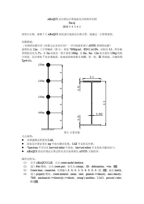
问题描述:(本例的问题引用《有限元法及其应用》一书中陆新征博士ANSYS算例的问题)悬臂柱高12m,工字型截面(图1),密度7800kg/m3,EX=2.1e11Pa,泊松比0.3,所有振型的阻尼比为2%,在3m高处有一集中质量160kg,在6m、9m、12m处分别有120kg的集中质量。
反应谱按7度多遇地震,取地震影响系数为0.08,第一组,III类场地,卓越周期Tg=0.45s。
图1 计算对象几点说明:●本例建模过程使用CAE;●添加反应谱必须在inp中加关键词实现,CAE不支持反应谱;●*Spectrum不可以在keyword editor中添加,keyword editor不支持此关键词读入;●ABAQUS的反应谱法计算过程以及后处理要比ANSYS方便的多。
操作过程为:(1)打开ABAQUS/CAE,点击create model database。
(2)进入Part模块,点击create part,命名为column,3D、deformation、wire。
OK (3)Create lines:connected,分别输入0,0;0,3;0,6;0,9;0,12。
OK。
退出sketch。
(4)进入property模块,create material,name:steel,general-->>density,mass density:7800,mechanical-->>elasticity-->>elastic,young‘s modulus:2.1e11,poisson’s ratio:0.3.OK(5)Create section,name:I,category:beam,type:beam, Continue, create profile, name:I, shape:I, 按图1尺寸输入界面尺寸,ok。
ABAQUS时程分析法计算地震反应的简单实例
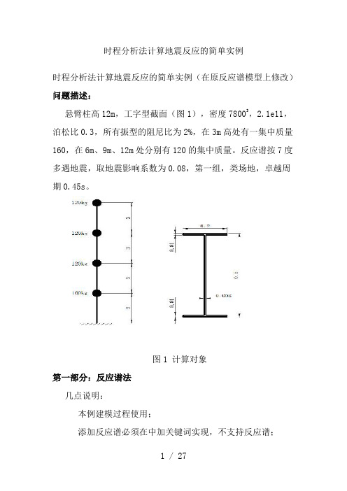
时程分析法计算地震反应的简单实例时程分析法计算地震反应的简单实例(在原反应谱模型上修改)问题描述:悬臂柱高12m,工字型截面(图1),密度78003,2.1e11,泊松比0.3,所有振型的阻尼比为2%,在3m高处有一集中质量160,在6m、9m、12m处分别有120的集中质量。
反应谱按7度多遇地震,取地震影响系数为0.08,第一组,类场地,卓越周期0.45s。
图1 计算对象第一部分:反应谱法几点说明:本例建模过程使用;添加反应谱必须在中加关键词实现,不支持反应谱;*不可以在中添加,不支持此关键词读入。
的反应谱法计算过程以及后处理要比方便的多。
操作过程为:(1)打开,点击。
(2)进入模块,点击,命名为,3D、、。
(3),在分别输入0,0回车;0,3回车;0,6回车;0,9回车;0,12回车。
(4)进入模块,,:,>>,:7800>>>>,‘s :2.1e11,’s :0.3.(5),:1,:,:,, : 1, ,按图1尺寸输入界面尺寸,。
在选择I,选择。
(6),选择全部,,弹出的对话框选择:1,。
(7),选择全部,默认值确定。
(8) >> ,在弹出的对话框里勾选,,以可视化梁截面形状。
(9)添加集中质量,>>>>,:1,:,,选择(0,3)位置点,:160,。
,:2,:,,选择0,6;0,9;0,12位置点(按多选),,:120,,。
(10) >> ,选(),。
(11) >> ,:1,选,在选项卡中,选择频率提取方法,本例选用法,,选,输入10。
再,,:2,选,在选项卡中,选择单向,选择()法,:(反应谱的,后面再中添加),方向余弦(0,0,1),:1.进入选项卡,阻尼使用直接模态(),勾选,:1,:8,:0.02。
(12)进入模块,>> ,:,选择,选择,选择,选择0,0点,,勾选u13所有6个自由度。
如何理解ABAQUS地震时程分析计算结果

手算 ABAQUS
1
2
3
4
5
时间/s
图 3 顶部加速度反应对比
用 ABAQUS 进行地震反应时程分析,结构反应(位移、速
度、加速度)结果应扣除基础(施加加速度处)的反应结果!
m
2000
工程频率计算: f = ω = 6.44(Hz) 2π
(2)ABAQUS 计算
工程频率计算: f = 6.44(Hz)
可见手算和 ABAQUS 计算结果一致。 4.时程计算
假设地面运动加速度时程 u&&(t)=sin(t),这与实际是不符的,这样假设是为
了求解微分方程方便! (1)手算
运动方程为: &y&(t) + ω2 y(t) = −u&&(t) 。
(3)计算结果对比
0.0008
0.0006
0.0004
0.0002
位移/m
Байду номын сангаас
0.0000
-0.0002
-0.0004
-0.0006
-0.0008 0
手算 ABAQUS
1
2
3
4
5
时间/s
图 3 顶部位移反应对比
0.03
0.02
0.01
加速度/m/s2
0.00
-0.01
-0.02
5.结论
-0.03
-0.04 0
大头模型的地震运动图示如下:
u(t)+y (t) y (t)
u (t )
图 2 运动图示
3.动力特性计算
(1)手算
体系的刚度系数计算: k
= 3EI
3× 2.1×109 × 0.5 × 0.53
ABAQUS软件在基于性能的地震时程分析上的应用
ABAQUS软件在基于性能的地震时程分析上的应用一、本文概述随着科技的发展和工程需求的提升,基于性能的地震时程分析(Performance-Based Earthquake Engineering, PBEE)已成为结构工程领域的研究热点。
在这种分析方法中,结构的抗震性能不再仅通过传统的承载能力来评估,而是更多地关注结构在地震作用下的实际表现,如变形、耗能等。
这为结构设计和抗震评估提供了新的视角和更高的要求。
ABAQUS软件作为一款功能强大的有限元分析软件,能够模拟结构在各种复杂工况下的力学行为,因此在基于性能的地震时程分析中得到了广泛应用。
本文旨在探讨ABAQUS软件在PBEE中的应用,介绍其基本原理、分析流程、关键技术及实际案例。
通过对ABAQUS软件在地震时程分析中的具体实践进行详细阐述,期望能为工程师和研究人员提供有益的参考和启示,推动基于性能的地震工程研究的深入发展。
二、ABAQUS软件简介ABAQUS是一款功能强大的工程模拟软件,广泛应用于各种工程领域的复杂问题求解,包括结构力学、流体动力学、热力学、电磁学等。
其强大的分析能力主要源于其丰富的材料模型库、精确的求解器以及灵活的用户界面。
ABAQUS以其高度的精确性和可靠性,在科研和工程实践中得到了广泛应用。
在结构工程领域,ABAQUS提供了丰富的单元类型和材料模型,可以满足从简单线性问题到复杂非线性问题的模拟需求。
其中,ABAQUS/Standard模块用于处理一般的线性和非线性问题,而ABAQUS/Explicit模块则特别适用于处理涉及冲击、爆炸等高度非线性动力学问题。
ABAQUS还提供了丰富的接触和连接类型,可以模拟各种复杂的结构连接形式。
在地震工程领域,ABAQUS的动力学分析能力尤为突出。
它不仅可以进行模态分析、反应谱分析等线性动力学分析,还可以进行直接积分法等非线性动力学分析。
这使得ABAQUS能够准确模拟地震波在结构中的传播过程,以及结构在地震作用下的动力响应。
abaqus帮助文档之地震相应计算分析
2.1.15Seismic analysis of a concrete gravity damProducts:Abaqus/Standard Abaqus/ExplicitIn this example we consider an analysis of the Koyna dam, which was subjected to an earthquake of magnitude 6.5 on the Richter scale on December 11, 1967. The example illustrates a typical application of the concrete damaged plasticity material model for the assessment of the structural stability and damage of concrete structures subjected to arbitrary loading. This problem is chosen because it has been extensively analyzed by a number of investigators, including Chopra and Chakrabarti(1973), Bhattacharjee andLéger(1993), Ghrib and Tinawi(1995), Cervera et al.(1996), and Lee and Fenves(1998). Problem descriptionThe geometry of a typical non-overflow monolith of the Koyna dam is illustrated in Figure 2.1.15–1. The monolith is 103m high and 71m wide at its base. The upstream wall of the monolith is assumed to be straight and vertical, which is slightly different from the real configuration. The depth of the reservoir at the time of the earthquake is= 91.75m. Following the work of other investigators, we consider a two-dimensional analysis of the non-overflow monolith assuming plane stress conditions. The finite element mesh used for the analysis is shown in Figure 2.1.15–2. It consists of 760 first-order, reduced-integration, plane stress elements (CPS4R). Nodal definitions are referred to a global rectangular coordinate system centered at the lower left corner of the dam, with the vertical y-axis pointing in the upward direction and the horizontal x-axis pointing in the downstream direction. The transverse and vertical components of the ground accelerations recorded during the Koyna earthquake are shown in Figure 2.1.15–3(units of g= 9.81m sec–2). Prior to the earthquake excitation, the dam is subjected to gravity loading due to its self-weight and to the hydrostatic pressure of the reservoir on the upstream wall. For the purpose of this example we neglect the dam–foundation interactions by assuming that the foundation is rigid. The dam–reservoir dynamic interactions resulting from the transverse component of ground motion can be modeled in a simple form using the Westergaard added mass technique. According to Westergaard (1933), the hydrodynamic pressures that the water exerts on the dam during an earthquake are the same as if a certain body of water moves back and forth with the dam while the remainder of the reservoir is left inactive. The added mass per unit area of theupstream wall is given in approximate form by the expression, with, where= 1000 kg/m3is the density of water. In the Abaqus/Standard analysis the added mass approach is implemented using a simple 2-node user element that has been coded in user subroutine UEL. In the Abaqus/Explicit analysis the dynamic interactions between the dam and the reservoir are ignored.The hydrodynamic pressures resulting from the vertical component of ground motion are assumed to be small and are neglected in all the simulations.Material propertiesThe mechanical behavior of the concrete material is modeled using the concrete damaged plasticity constitutive model described in“Concrete damaged plasticity,”Section 23.6.3 of the Abaqus Analysis User's Manual, and“Damaged plasticity model for concrete and other quasi-brittle materials,”Section 4.5.2 of the Abaqus Theory Manual. The material properties used for the simulations are given in Table 2.1.15–1and Figure 2.1.15–4. These properties are assumed to be representative of the concrete material in the Koyna dam and are based on the properties used by previous investigators. In obtaining some of these material properties, a number of assumptions are made. Of particular interest is the calibration of the concrete tensile behavior. The tensile strength is estimated to be 10% of the ultimate compressive strength (= 24.1MPa), multiplied by a dynamic amplification factor of 1.2 to account for rate effects; thus,= 2.9MPa. To avoid unreasonable mesh-sensitive results due to the lack of reinforcement in the structure, the tensile postfailure behavior is given in terms of a fracture energy cracking criterion by specifying a stress/displacement curve instead of a stress-strain curve, as shown in Figure 2.1.15–4(a). This is accomplished with the postcracking stress/displacement curve. Similarly, tensile damage,, is specified in tabular form as a function of cracking displacement by using the postcracking damage displacement curve. This curve is shown in Figure 2.1.15–4(b). The stiffness degradation damage caused by compressive failure (crushing) of the concrete,, is assumed to be zero.DampingIt is generally accepted that dams have damping ratios of about 2–5%. In this example we tune the material damping properties to provide approximately 3% fraction of critical damping for the first mode of vibration of the dam. Assuming Rayleigh stiffness proportional damping, the factor required to provide a fraction of critical damping for the first mode is givenas. From a natural frequency extraction analysis of the dam the first eigenfrequency is found to be= 18.61 rad sec–1(see Table 2.1.15–2). Based on this,is chosen to be 3.23 × 10⁻³sec.Loading and solution controlLoading conditions and solution controls are discussed for each analysis.Abaqus/Standard analysisPrior to the dynamic simulation of the earthquake, the dam is subjected to gravity loading and hydrostatic pressure. In the Abaqus/Standard analysis these loads are specified in two consecutive static steps, using a distributed load with the load type labels GRA V(for the gravity load) in the first step and HP(for the hydrostatic pressure) in the second step. For the dynamic analysis in the third step the transverse and vertical components of the ground accelerations shown in Figure 2.1.15–3are applied to all nodes at the base of the dam.Since considerable nonlinearity is expected in the response, including the possibility of unstable regimes as the concrete cracks, the overall convergence of the solution in the Abaqus/Standard analysis is expected to be non-monotonic. In such cases automatically setting the time incrementation parameters is generally recommended to prevent premature termination of the equilibrium iteration process because the solution may appear to be diverging. The unsymmetric matrix storage and solution scheme is activated by specifying an unsymmetric equation solver for the step. This is essential for obtaining an acceptable rate of convergence with the concrete damaged plasticity model since plastic flow is nonassociated. Automatic time incrementation isused for the dynamic analysis of the earthquake, with the half-increment residual tolerance set to 107and a maximum time increment of 0.02 sec.Abaqus/Explicit analysisWhile it is possible to perform the analysis of the pre-seismic state in Abaqus/Explicit, Abaqus/Standard is much more efficient at solving quasi-static analyses. Therefore, we apply the gravity and hydrostatic loads in an Abaqus/Standard analysis. These results are then imported into Abaqus/Explicit to continue with the seismic analysis of the dam subjected to the earthquake accelerogram. We still need to continue to apply the gravity and hydrostatic pressure loads during the explicit dynamic step. In Abaqus/Explicit gravity loading is specified in exactly the same way as in Abaqus/Standard. The specification of the hydrostatic pressure, however, requires some extra consideration because this load type is not currently supported by Abaqus/Explicit. Here we apply the hydrostatic pressure using user subroutine VDLOAD.The Abaqus/Explicit simulation requires a very large number of increments since the stable time increment (6 × 10⁻⁶sec) is much smaller than the total duration of the earthquake (10 sec). The analysis is run in double precision to prevent the accumulation of round-off errors. The stability limit could be increased by using mass scaling; however, this may affect the dynamic response of the structure.For this particular problem Abaqus/Standard is computationally more effective than Abaqus/Explicit because the earthquake is a relatively long event that requires a very large number of increments in Abaqus/Explicit. In addition, the size of the finite element model is small, and the cost of each solution of the global equilibrium equations in Abaqus/Standard is quite inexpensive.Results and discussionThe results for each analysis are discussed in the following sections.Abaqus/Standard resultsThe results from a frequency extraction analysis of the dam without the reservoir are summarized in Table 2.1.15–2. The first four natural frequencies of the finite element model are in good agreement with the values reported by Chopra and Chakrabarti(1973). As discussed above, the frequency extraction analysis is useful for the calibration of the material damping to be used during the dynamic simulation of the earthquake.Figure 2.1.15–5shows the horizontal displacement at the left corner of the crest of the dam relative to the ground motion. In this figure positive values represent displacement in the downstream direction. The crest displacement remains less than 30mm during the first 4 seconds of the earthquake. After 4seconds, the amplitude of the oscillations of the crest increases substantially. As discussed below, severe damage to the structure develops during these oscillations.The concrete material remains elastic with no damage at the end of the second step, after the dam has been subjected to the gravity and hydrostatic pressure loads. Damage to the dam initiates during the seismic analysis in the third step. The evolution of damage in the concrete dam at six different times during the earthquake is illustrated in Figure 2.1.15–6,Figure 2.1.15–7, and Figure 2.1.15–8. Times= 3.96sec,= 4.315sec, and= 4.687sec correspond to the first three large excursions of the crest in the upstream direction, as shown in Figure 2.1.15–5. Times= 4.163sec and= 4.526sec correspond to the first two large excursions of the crest in the downstream direction. Time= 10 sec corresponds to the end of the earthquake. The figuresshow the contour plots of the tensile damage variable,DAMAGET(or), on the left, and the stiffness degradation variable,SDEG(or d), on the right. The tensile damage variable is a nondecreasing quantity associated with tensile failure of the material. On the other hand, the stiffness degradation variable can increase or decrease, reflecting the stiffness recovery effects associated with the opening/closing of cracks. Thus, assuming that there is no compressive damage (), the combination and at a given material point represents an open crack, whereas and represents a closed crack.At time, damage has initiated at two locations: at the base of the dam on the upstream face and in the region near the stress concentration where the slope on the downstream face changes. When the dam displaces toward the downstream direction at time, the damage at the base leads to the formation of a localized crack-like band of damaged elements. This crack propagates into the dam along the dam–foundation boundary. The nucleation of this crack is induced by the stress concentration in this area due to the infinitely rigid foundation. At this time, some partial tensile damage is also observed on several elements along the upstream face.During the next large excursion in the upstream direction, at time, a localized band of damaged elements forms near the downstream change of slope. As this downstream crack propagates toward the upstream direction, it curves down due to the rocking motion of the top block of the dam. The crack at the base of the dam is closed at time by the compressive stresses in this region. This is easily verified by looking at the contour plot of SDEG at time, which clearly shows that the stiffness is recovered on this region, indicating that the crack is closed.When the load is reversed, corresponding to the next excursion in the downstream direction at time, the downstream crack closes and the stiffness is recovered on that region. At this time tensile damage localizes on several elements along the upstream face, leading to the formation of a horizontal crack that propagates toward the downstream crack.As the upper block of the dam oscillates back and forth during the remainder of the earthquake, the upstream and downstream cracks close and open in an alternate fashion. The dam retains its overall structural stability since both cracks are never under tensile stress during the earthquake. The distribution of tensile damage at the end of the earthquake is shown in Figure 2.1.15–8, at time. The contour plot of the stiffness degradation variable indicates that, except at the vicinity of the crack tips, all cracks are closed under compressive stresses and most of the stiffness is recovered. No compressive failure is observed during the simulation. The damage patterns predicted by Abaqus are consistent with those reported by other investigators.Abaqus/Explicit resultsFigure 2.1.15–9shows the distribution of tensile damage at the end of the Abaqus/Explicit simulation. Two major cracks develop during the earthquake, one at the base of the dam and the other at the downstream change of slope. If we compare these results with those from the analysis in Abaqus/Standard (see Figure 2.1.15–8at time), we find that Abaqus/Standard predicted additional damage localization zones on the upstream face of the dam. The differences between the results are due to the effect of the dam–reservoir hydrodynamic interactions, which are included in the Abaqus/Standard simulation via an added-mass user element and are ignored in Abaqus/Explicit. This is easily verified by running an Abaqus/Standard analysis without the added-mass user element. The results from this analysis, shown in Figure 2.1.15–10, are consistent with the Abaqus/Explicit results in Figure 2.1.15–9and confirm that additional damage to the upstream wall occurs when the hydrodynamic interactions are taken into account.Input filesAbaqus/Standard input files1、Frequency analysis of the Koyna dam.*HEADINGKOYNA DAM: NA TURAL FREQUENCY EXTRACTION Units - n, m, sec*PREPRINT, MODEL=YES*NODE1 , 0.00, 0.0021, 70.00, 0.002401, 0.00, 66.502421, 19.25, 66.503601, 0.00, 91.753621, 16.17, 91.753801, 0.00, 103.003821, 14.80, 103.00*NGEN, NSET=NBASE1, 21*NGEN, NSET=NMID2401, 2421*NGEN, NSET=NWL3601, 3621*NGEN, NSET=NTOP3801, 3821*NFILL, BIAS=1.05NBASE, NMID, 24, 100*NFILL, BIAS=0.92NMID, NWL, 12, 100*NFILLNWL, NTOP, 2, 100*ELEMENT, TYPE=CPS4R1, 1, 2, 102, 101*ELGEN, ELSET=DAM1, 20, 1, 1, 38, 100, 100*ELSET, ELSET=WDAM, GENERATE1, 3501, 100*SOLID SECTION, ELSET=DAM, MA TERIAL=CONCRETE 1.0,*MATERIAL, NAME=CONCRETE*ELASTIC3.1027E+10, 0.2*DENSITY2643.0*CONCRETE DAMAGED PLASTICITY36.31*CONCRETE COMPRESSION HARDENING13.0E+6, 0.024.1E+6, 0.001*CONCRETE TENSION STIFFENING, TYPE=DISPLACEMENT2.9E+6 ,01.94393E+6 ,0.0000661851.30305E+6 ,0.000122860.873463E+6 ,0.0001734270.5855E+6 ,0.000220190.392472E+6 ,0.0002647180.263082E+6 ,0.0003080880.176349E+6 ,0.000351050.11821E+6 ,0.0003941380.0792388E+6 ,0.0004377440.0531154E+6 ,0.000482165*CONCRETE TENSION DAMAGE, TYPE=DISPLACEMENT0 ,00.381217 ,0.0000661850.617107 ,0.000122860.763072 ,0.0001734270.853393 ,0.000220190.909282 ,0.0002647180.943865 ,0.0003080880.965265 ,0.000351050.978506 ,0.0003941380.9867 ,0.0004377440.99177 ,0.000482165*BOUNDARYNBASE, 1,2*STEP, NLGEOMSTEP 1 - GRA VITY LOAD*STATIC1.0E-10, 1.0E-10*DLOADDAM, GRA V, 9.81, 0, -1*END STEP*STEPSTEP 2 - FREQUENCY EXTRACTION*FREQUENCY4,*END STEP2、Seismic analysis of the Koyna dam, including hydrodynamic interactions. *HEADINGKOYNA DAM: SEISMIC ANAL YSISUnits - n, m, sec********************************************* ** Step 1: Gravity load** Step 2: Hydrostatic pressure load** Step 3: Earthquake including hydrodynamic**interactions**** Requires FORTRAN subroutine addedmass_uel,** and amplitude curves koyna_haccel.inp and** koyna_vaccel.inp**** Execution command:** abaqus job=koyna_std user=addedmass_uel********************************************* *PREPRINT, MODEL=YES*NODE1 , 0.00, 0.0021, 70.00, 0.002401, 0.00, 66.502421, 19.25, 66.503601, 0.00, 91.753621, 16.17, 91.753801, 0.00, 103.003821, 14.80, 103.00*NGEN, NSET=NBASE1, 21*NGEN, NSET=NMID2401, 2421*NGEN, NSET=NWL3601, 3621*NGEN, NSET=NTOP3801, 3821*NFILL, BIAS=1.05NBASE, NMID, 24, 100*NFILL, BIAS=0.92NMID, NWL, 12, 100*NFILLNWL, NTOP, 2, 100*NSET, NSET=NOUT1, 3801*ELSET, ELSET=EOUT2320, 2420*ELEMENT, TYPE=CPS4R1, 1, 2, 102, 101*ELGEN, ELSET=DAM1, 20, 1, 1, 38, 100, 100*ELSET, ELSET=WDAM, GENERATE1, 3501, 100*USER ELEMENT, NODES=2, TYPE=U1, PROP=3, COORD=2 1, 2*ELEMENT, TYPE=U110001, 1, 101*ELGEN, ELSET=ADDED_MASS10001, 36, 100, 1*UEL PROPERTY, ELSET=ADDED_MASS91.75, 91.75, 1000.0*SOLID SECTION, ELSET=DAM, MA TERIAL=CONCRETE 1.0,*MATERIAL, NAME=CONCRETE*ELASTIC3.1027E+10, 0.2*DENSITY2643.0*DAMPING, BETA=0.00323*CONCRETE DAMAGED PLASTICITY36.31*CONCRETE COMPRESSION HARDENING13.0E+6, 0.024.1E+6, 0.001*CONCRETE TENSION STIFFENING, TYPE=DISPLACEMENT 2.9E+6 ,01.94393E+6 ,0.0000661851.30305E+6 ,0.000122860.873463E+6 ,0.0001734270.5855E+6 ,0.000220190.392472E+6 ,0.0002647180.263082E+6 ,0.0003080880.176349E+6 ,0.000351050.11821E+6 ,0.0003941380.0792388E+6 ,0.0004377440.0531154E+6 ,0.000482165*CONCRETE TENSION DAMAGE, TYPE=DISPLACEMENT0 ,00.381217 ,0.0000661850.617107 ,0.000122860.763072 ,0.0001734270.853393 ,0.000220190.909282 ,0.0002647180.943865 ,0.0003080880.965265 ,0.000351050.978506 ,0.0003941380.9867 ,0.0004377440.99177 ,0.000482165*BOUNDARYNBASE, 1,2*AMPLITUDE, NAME=HAMP, INPUT=koyna_haccel.inp*AMPLITUDE, NAME=V AMP, INPUT=koyna_vaccel.inp***STEP, NLGEOM, UNSYMM=YESSTEP 1 - GRA VITY LOAD*STATIC1.0E-10, 1.0E-10*DLOADDAM, GRA V, 9.81, 0, -1*OUTPUT, FIELD, V ARIABLE=PRESELECT, FREQ=10*ELEMENT OUTPUTS,PE,LE,PEEQ,PEEQT,DAMAGEC,DAMAGET,SDEG*OUTPUT, HISTORY, V ARIABLE=PRESELECT, FREQ=1*ELEMENT OUTPUT, ELSET=EOUTSP1*NODE OUTPUT, NSET=NOUTU*END STEP***STEP, NLGEOM, UNSYMM=YESSTEP 2 - HYDROSTA TIC LOAD*STATIC1.0E-10, 1.0E-10*DLOADWDAM, HP4, 900067.6, 91.75, 0*END STEP***STEP, INC=2000, NLGEOM, UNSYMM=YESSTEP 3 - EARTHQUAKE*DYNAMIC, HAFTOL=1.0E70.02, 10.0, 1E-15,0.02*CONTROLS,PARAMETERS=FIELD1.E-5*BOUNDARY,TYPE=ACCELERATION,AMPLITUDE=HAMP NBASE,1,1,9.81*BOUNDARY,TYPE=ACCELERATION,AMPLITUDE=V AMPNBASE,2,2,9.81***CONTROLS, ANAL YSIS=DISCONTINUOUS*END STEP3、Seismic analysis of the Koyna dam, not including hydrodynamic interactions. *HEADINGKOYNA DAM: SEISMIC ANAL YSIS(without hydrodynamic interactions)Units - n, m, sec*************************************************** Step 1: Gravity load** Step 2: Hydrostatic pressure load** Step 3: Earthquake** (without hydrodynamic interactions)**** Requires amplitude curves koyna_haccel.inp** and koyna_vaccel.inp**************************************************PREPRINT, MODEL=YES*NODE1 , 0.00, 0.0021, 70.00, 0.002401, 0.00, 66.502421, 19.25, 66.503601, 0.00, 91.753621, 16.17, 91.753801, 0.00, 103.003821, 14.80, 103.00*NGEN, NSET=NBASE1, 21*NGEN, NSET=NMID2401, 2421*NGEN, NSET=NWL3601, 3621*NGEN, NSET=NTOP3801, 3821*NFILL, BIAS=1.05NBASE, NMID, 24, 100*NFILL, BIAS=0.92NMID, NWL, 12, 100*NFILLNWL, NTOP, 2, 100*NSET, NSET=NOUT1, 3801*ELSET, ELSET=EOUT2320, 2420*ELEMENT, TYPE=CPS4R1, 1, 2, 102, 101*ELGEN, ELSET=DAM1, 20, 1, 1, 38, 100, 100*ELSET, ELSET=WDAM, GENERATE1, 3501, 100*SOLID SECTION, ELSET=DAM, MA TERIAL=CONCRETE 1.0,*MATERIAL, NAME=CONCRETE*ELASTIC3.1027E+10, 0.2*DENSITY2643.0*DAMPING, BETA=0.00323*CONCRETE DAMAGED PLASTICITY36.31*CONCRETE COMPRESSION HARDENING13.0E+6, 0.024.1E+6, 0.001*CONCRETE TENSION STIFFENING, TYPE=DISPLACEMENT 2.9E+6 ,01.94393E+6 ,0.0000661851.30305E+6 ,0.000122860.873463E+6 ,0.0001734270.5855E+6 ,0.000220190.392472E+6 ,0.0002647180.263082E+6 ,0.0003080880.176349E+6 ,0.000351050.11821E+6 ,0.0003941380.0792388E+6 ,0.0004377440.0531154E+6 ,0.000482165*CONCRETE TENSION DAMAGE, TYPE=DISPLACEMENT0 ,00.381217 ,0.0000661850.617107 ,0.000122860.763072 ,0.0001734270.853393 ,0.000220190.909282 ,0.0002647180.943865 ,0.0003080880.965265 ,0.000351050.978506 ,0.0003941380.9867 ,0.0004377440.99177 ,0.000482165*BOUNDARYNBASE, 1,2*AMPLITUDE, NAME=HAMP, INPUT=koyna_haccel.inp*AMPLITUDE, NAME=V AMP, INPUT=koyna_vaccel.inp***STEP, NLGEOM, UNSYMM=YESSTEP 1 - GRA VITY LOAD*STATIC1.0E-10, 1.0E-10*DLOADDAM, GRA V, 9.81, 0, -1*OUTPUT, FIELD, V ARIABLE=PRESELECT, FREQ=10*ELEMENT OUTPUTS,PE,LE,PEEQ,PEEQT,DAMAGEC,DAMAGET,SDEG*OUTPUT, HISTORY, V ARIABLE=PRESELECT, FREQ=1*ELEMENT OUTPUT, ELSET=EOUTSP1*NODE OUTPUT, NSET=NOUTU*END STEP***STEP, NLGEOM, UNSYMM=YESSTEP 2 - HYDROSTA TIC LOAD*STATIC1.0E-10, 1.0E-10*DLOADWDAM, HP4, 900067.6, 91.75, 0*END STEP***STEP, INC=2000, NLGEOM, UNSYMM=YESSTEP 3 - EARTHQUAKE*DYNAMIC, HAFTOL=1.0E70.02, 10.0, 1E-15,0.02*CONTROLS,PARAMETERS=FIELD1.E-5*BOUNDARY,TYPE=ACCELERATION,AMPLITUDE=HAMP NBASE,1,1,9.81*BOUNDARY,TYPE=ACCELERATION,AMPLITUDE=V AMP NBASE,2,2,9.81***CONTROLS, ANAL YSIS=DISCONTINUOUS*END STEP4、Transverse ground acceleration record.** Horizontal accelerogram of Koyna earthquake0.00000E+00, 0.00000E+00, 0.10000E-01, 0.12650E-01, 0.20000E-01, 0.11990E-01, 0.30000E-01, 0.11330E-01, 0.40000E-01, 0.10670E-01, 0.50000E-01, 0.98100E-02, 0.60000E-01, 0.23900E-02, 0.70000E-01,-0.50200E-02, 0.80000E-01,-0.12430E-01, 0.90000E-01,-0.18890E-01, 0.10000E+00,-0.10440E-01, 0.11000E+00,-0.19800E-02, 0.12000E+00, 0.64700E-02, 0.13000E+00, 0.88000E-03, 0.14000E+00,-0.14880E-01, 0.15000E+00,-0.28860E-01, 0.16000E+00,-0.24910E-01, 0.17000E+00,-0.20970E-01, 0.18000E+00,-0.17020E-01, 0.19000E+00,-0.13070E-01, 0.20000E+00,-0.91200E-02, 0.21000E+00,-0.51700E-02, 0.22000E+00,-0.12200E-02, 0.23000E+00,-0.17500E-02, 0.24000E+00,-0.47800E-02, 0.25000E+00,-0.78200E-02, 0.26000E+00,-0.10860E-01, 0.27000E+00,-0.13900E-01, 0.28000E+00,-0.16940E-01, 0.29000E+00,-0.17770E-01, 0.30000E+00,-0.85700E-02, 0.31000E+00, 0.64000E-03, 0.32000E+00, 0.98500E-02, 0.33000E+00, 0.19060E-01, 0.34000E+00, 0.24360E-01, 0.35000E+00, 0.14960E-01, 0.36000E+00, 0.55600E-02, 0.37000E+00,-0.38300E-02, 0.38000E+00,-0.12000E-02, 0.39000E+00, 0.58800E-02, 0.40000E+00, 0.12970E-01, 0.41000E+00, 0.55300E-02, 0.42000E+00,-0.16410E-01, 0.43000E+00,-0.38360E-01, 0.44000E+00,-0.37050E-01, 0.45000E+00,-0.14260E-01, 0.46000E+00, 0.85300E-02, 0.47000E+00, 0.31320E-01, 0.48000E+00, 0.31950E-01, 0.49000E+00, 0.26700E-01, 0.50000E+00, 0.25790E-01, 0.51000E+00, 0.35010E-01, 0.52000E+00, 0.44240E-01, 0.53000E+00, 0.34400E-01, 0.54000E+00, 0.20370E-01, 0.55000E+00, 0.63400E-02, 0.56000E+00,-0.60100E-02, 0.57000E+00,-0.13100E-02, 0.58000E+00, 0.33800E-02, 0.59000E+00, 0.80800E-02, 0.60000E+00, 0.64700E-02, 0.61000E+00, 0.82000E-03, 0.62000E+00, 0.11550E-01, 0.63000E+00, 0.24730E-01, 0.64000E+00, 0.37900E-01, 0.65000E+00, 0.51080E-01, 0.66000E+00, 0.50240E-01, 0.67000E+00, 0.47850E-01, 0.68000E+00, 0.39170E-01, 0.69000E+00,-0.25300E-02, 0.70000E+00,-0.44230E-01, 0.71000E+00,-0.75110E-01, 0.72000E+00,-0.56710E-01, 0.73000E+00,-0.38300E-01, 0.74000E+00,-0.19900E-01, 0.75000E+00,-0.10370E-01, 0.76000E+00,-0.11690E-01, 0.77000E+00,-0.13010E-01, 0.78000E+00, 0.94780E-01, 0.79000E+00, 0.71310E-01, 0.80000E+00, 0.43670E-01, 0.81000E+00, 0.16030E-01, 0.82000E+00,-0.11600E-01, 0.83000E+00,-0.39240E-01, 0.84000E+00,-0.18150E-01, 0.85000E+00, 0.29400E-02, 0.86000E+00, 0.24030E-01, 0.87000E+00, 0.31490E-01, 0.88000E+00, 0.39100E-02, 0.89000E+00,-0.23670E-01, 0.90000E+00,-0.20300E-02, 0.91000E+00, 0.32700E-01, 0.92000E+00, 0.63640E-01, 0.93000E+00, 0.35200E-01, 0.94000E+00, 0.67600E-02, 0.95000E+00,-0.19350E-01, 0.96000E+00,-0.14620E-01, 0.97000E+00,-0.98900E-02, 0.98000E+00,-0.51500E-02, 0.99000E+00,-0.42000E-03, 0.10000E+01, 0.43100E-02, 0.10100E+01, 0.90400E-02, 0.10200E+01, 0.34000E-02, 0.10300E+01,-0.39400E-02, 0.10400E+01, 0.10820E-01, 0.10500E+01, 0.38540E-01, 0.10600E+01, 0.43160E-01, 0.10700E+01, 0.11640E-01, 0.10800E+01,-0.19880E-01, 0.10900E+01,-0.40000E-03, 0.11000E+01, 0.24740E-01, 0.11100E+01, 0.42490E-01, 0.11200E+01, 0.24100E-01, 0.11300E+01, 0.57100E-02, 0.11400E+01, 0.16100E-02, 0.11500E+01, 0.42400E-02, 0.11600E+01, 0.37100E-02, 0.11700E+01,-0.94600E-02, 0.11800E+01,-0.22640E-01, 0.11900E+01,-0.26450E-01, 0.12000E+01, 0.29000E-02, 0.12100E+01, 0.32250E-01, 0.12200E+01, 0.61600E-01, 0.12300E+01, 0.48040E-01, 0.12400E+01, 0.34050E-01, 0.12500E+01, 0.20060E-01, 0.12600E+01, 0.60700E-02, 0.12700E+01,-0.79200E-02, 0.12800E+01,-0.21910E-01, 0.12900E+01,-0.16220E-01, 0.13000E+01,-0.46500E-02, 0.13100E+01, 0.69300E-02, 0.13200E+01, 0.18500E-01, 0.13300E+01, 0.30070E-01, 0.13400E+01, 0.30620E-01, 0.13500E+01, 0.29910E-01, 0.13600E+01, 0.32540E-01, 0.13700E+01, 0.35170E-01, 0.13800E+01, 0.20130E-01, 0.13900E+01, 0.14700E-02, 0.14000E+01,-0.17190E-01, 0.14100E+01,-0.68100E-02, 0.14200E+01, 0.86900E-02, 0.14300E+01, 0.21460E-01, 0.14400E+01, 0.12060E-01, 0.14500E+01, 0.10380E-01, 0.14600E+01, 0.21880E-01, 0.14700E+01, 0.27750E-01, 0.14800E+01, 0.24450E-01, 0.14900E+01, 0.21150E-01, 0.15000E+01, 0.26130E-01, 0.15100E+01, 0.43530E-01, 0.15200E+01, 0.60940E-01, 0.15300E+01, 0.72470E-01, 0.15400E+01, 0.55300E-01, 0.15500E+01, 0.38140E-01, 0.15600E+01, 0.20980E-01, 0.15700E+01, 0.38200E-02, 0.15800E+01,-0.13340E-01, 0.15900E+01,-0.30510E-01, 0.16000E+01,-0.30440E-01, 0.16100E+01,-0.10160E-01, 0.16200E+01, 0.10130E-01, 0.16300E+01, 0.30420E-01, 0.16400E+01, 0.28080E-01, 0.16500E+01, 0.25280E-01, 0.16600E+01, 0.22480E-01, 0.16700E+01, 0.19680E-01, 0.16800E+01, 0.81130E-01, 0.16900E+01, 0.16287E+00, 0.17000E+01, 0.15773E+00, 0.17100E+01, 0.72390E-01, 0.17200E+01,-0.12940E-01, 0.17300E+01,-0.98280E-01, 0.17400E+01,-0.18361E+00, 0.17500E+01,-0.26895E+00,0.17600E+01,-0.18618E+00, 0.17700E+01,-0.63990E-01, 0.17800E+01, 0.58200E-01, 0.17900E+01, 0.16639E+00, 0.18000E+01, 0.11351E+00, 0.18100E+01, 0.60620E-01, 0.18200E+01, 0.77400E-02, 0.18300E+01,-0.45150E-01, 0.18400E+01,-0.34850E-01, 0.18500E+01,-0.13400E-01, 0.18600E+01, 0.80600E-02, 0.18700E+01,-0.26710E-01, 0.18800E+01,-0.95930E-01, 0.18900E+01,-0.11861E+00, 0.19000E+01,-0.68500E-01, 0.19100E+01,-0.18390E-01, 0.19200E+01,-0.37100E-02, 0.19300E+01,-0.26700E-02, 0.19400E+01, 0.26890E-01, 0.19500E+01, 0.49190E-01, 0.19600E+01, 0.36010E-01, 0.19700E+01, 0.30160E-01, 0.19800E+01, 0.27750E-01, 0.19900E+01, 0.25350E-01, 0.20000E+01,-0.46900E-01, 0.20100E+01,-0.12281E+00, 0.20200E+01,-0.98920E-01, 0.20300E+01,-0.34250E-01, 0.20400E+01, 0.30420E-01, 0.20500E+01, 0.95080E-01, 0.20600E+01, 0.15975E+00, 0.20700E+01, 0.18416E+00, 0.20800E+01, 0.87810E-01, 0.20900E+01,-0.85500E-02, 0.21000E+01,-0.10490E+00, 0.21100E+01,-0.20126E+00, 0.21200E+01,-0.17064E+00, 0.21300E+01,-0.10209E+00, 0.21400E+01,-0.66120E-01, 0.21500E+01,-0.10992E+00, 0.21600E+01,-0.14704E+00, 0.21700E+01,-0.57080E-01, 0.21800E+01,-0.39630E-01, 0.21900E+01,-0.79160E-01, 0.22000E+01,-0.11869E+00, 0.22100E+01,-0.15822E+00, 0.22200E+01,-0.83860E-01, 0.22300E+01, 0.21156E+00, 0.22400E+01, 0.35435E+00, 0.22500E+01, 0.21368E+00, 0.22600E+01, 0.73000E-01, 0.22700E+01,-0.67670E-01, 0.22800E+01,-0.20835E+00, 0.22900E+01,-0.24427E+00, 0.23000E+01,-0.10928E+00, 0.23100E+01, 0.25710E-01, 0.23200E+01, 0.16069E+00, 0.23300E+01, 0.16925E+00, 0.23400E+01, 0.10973E+00, 0.23500E+01, 0.50210E-01, 0.23600E+01,-0.93100E-02, 0.23700E+01,-0.68830E-01, 0.23800E+01,-0.71660E-01, 0.23900E+01, 0.68000E-03, 0.24000E+01, 0.73020E-01, 0.24100E+01, 0.14535E+00, 0.24200E+01, 0.11531E+00, 0.24300E+01, 0.79880E-01, 0.24400E+01, 0.44450E-01, 0.24500E+01, 0.90200E-02, 0.24600E+01, 0.20877E+00, 0.24700E+01, 0.20674E+00, 0.24800E+01, 0.12830E+00, 0.24900E+01, 0.49860E-01, 0.25000E+01,-0.28580E-01, 0.25100E+01,-0.10702E+00, 0.25200E+01,-0.11965E+00, 0.25300E+01,-0.69050E-01, 0.25400E+01,-0.18440E-01, 0.25500E+01, 0.13010E-01, 0.25600E+01,-0.47700E-02, 0.25700E+01,-0.22540E-01, 0.25800E+01,-0.40320E-01, 0.25900E+01,-0.58100E-01, 0.26000E+01,-0.14990E-01, 0.26100E+01, 0.16363E+00, 0.26200E+01, 0.15271E+00, 0.26300E+01, 0.10019E+00, 0.26400E+01, 0.47660E-01, 0.26500E+01,-0.48600E-02, 0.26600E+01,-0.57380E-01, 0.26700E+01,-0.10991E+00, 0.26800E+01,-0.16243E+00, 0.26900E+01,-0.21495E+00, 0.27000E+01,-0.26748E+00, 0.27100E+01,-0.27359E+00, 0.27200E+01,-0.12434E+00, 0.27300E+01, 0.24910E-01, 0.27400E+01, 0.13502E+00, 0.27500E+01, 0.23340E-01, 0.27600E+01,-0.88350E-01, 0.27700E+01,-0.20004E+00, 0.27800E+01,-0.31172E+00, 0.27900E+01,-0.25999E+00, 0.28000E+01,-0.12776E+00, 0.28100E+01, 0.44700E-02, 0.28200E+01, 0.13669E+00, 0.28300E+01, 0.26892E+00, 0.28400E+01, 0.25423E+00, 0.28500E+01, 0.17658E+00, 0.28600E+01, 0.98930E-01, 0.28700E+01, 0.21280E-01, 0.28800E+01,-0.56370E-01, 0.28900E+01,-0.53320E-01, 0.29000E+01,-0.20430E-01, 0.29100E+01, 0.12460E-01, 0.29200E+01, 0.45350E-01, 0.29300E+01, 0.78240E-01, 0.29400E+01, 0.11113E+00, 0.29500E+01, 0.14402E+00, 0.29600E+01, 0.17691E+00, 0.29700E+01, 0.20980E+00, 0.29800E+01, 0.19554E+00, 0.29900E+01, 0.65860E-01, 0.30000E+01,-0.63820E-01, 0.30100E+01,-0.19351E+00, 0.30200E+01,-0.13931E+00, 0.30300E+01,-0.41970E-01, 0.30400E+01, 0.55360E-01, 0.30500E+01, 0.15270E+00, 0.30600E+01, 0.25003E+00, 0.30700E+01, 0.32433E+00, 0.30800E+01, 0.19131E+00, 0.30900E+01, 0.58290E-01, 0.31000E+01,-0.74730E-01, 0.31100E+01,-0.20774E+00, 0.31200E+01,-0.34076E+00, 0.31300E+01,-0.47378E+00, 0.31400E+01,-0.30489E+00, 0.31500E+01,-0.94830E-01, 0.31600E+01, 0.11523E+00, 0.31700E+01, 0.27682E+00, 0.31800E+01, 0.18387E+00, 0.31900E+01, 0.90930E-01, 0.32000E+01,-0.20100E-02, 0.32100E+01,-0.94950E-01, 0.32200E+01,-0.18789E+00, 0.32300E+01,-0.28083E+00, 0.32400E+01,-0.37377E+00, 0.32500E+01,-0.19456E+00, 0.32600E+01, 0.10129E+00, 0.32700E+01, 0.25356E+00, 0.32800E+01,-0.10327E+00, 0.32900E+01,-0.75620E-01, 0.33000E+01,-0.36080E-01, 0.33100E+01,-0.35800E-01, 0.33200E+01,-0.76360E-01, 0.33300E+01,-0.11692E+00, 0.33400E+01,-0.15748E+00, 0.33500E+01,-0.19804E+00, 0.33600E+01,-0.23861E+00, 0.33700E+01,-0.24706E+00, 0.33800E+01,-0.17296E+00, 0.33900E+01,-0.98850E-01, 0.34000E+01,-0.24750E-01, 0.34100E+01, 0.49360E-01, 0.34200E+01, 0.12346E+00, 0.34300E+01, 0.19049E+00, 0.34400E+01, 0.14661E+00, 0.34500E+01, 0.10272E+00, 0.34600E+01, 0.58840E-01, 0.34700E+01, 0.14960E-01, 0.34800E+01,-0.28920E-01, 0.34900E+01,-0.72810E-01, 0.35000E+01,-0.11669E+00, 0.35100E+01,-0.16057E+00,。
Abaqus地震分析的总结
4、关于单元尺寸、最小增量步时间
4.1 单元尺寸 有限单元长度必须小于最大频率对应波长的 1/10-1/8,因此滤掉高频波后可以增大单元尺寸
详见 Parametric study on seismic ground response by finite element modeling 4.2 时步选择 常选择 0.005,但精确的选择如下:
Abaqus 地震分析的总结——时步、单元尺寸、滤波、等效非线性、无限元 笑看风云
1、自由场地震反应
经典的自由场地震反应用 shake91 或 proshake 等进行分析,在分析完可以导出各层土的等效线性参数,包 括阻尼(粘滞阻尼系数)和剪切模量,用剪切模量可以计算弹性模量,shake 中假定泊松比为常数,对地震 反应没影响。其实 FLAC 中有自带自由场边界,计算地震很方便。 如以下是 shake91 中自带的例子输出得到的参数 ITERATION NUMBER 8 VALUES IN TIME DOMAIN NO TYPE DEPTH UNIFRM. <---- DAMPING ----> <---- SHEAR MODULUS -----> G/Go (FT) STRAIN NEW USED ERROR NEW USED ERROR RATIO --- ---- ---- ------- ----- ------ ------------ ------- ------ ----1 2 2.5 .00077 .007 .007 .0 3851.5 3851.5 .0 .992 2 2 7.5 .00295 .014 .014 .0 3020.0 3020.0 .0 .960 3 2 15.0 .00634 .023 .023 .0 2803.8 2803.8 .0 .892 4 2 25.0 .00976 .028 .028 .0 2985.8 2985.8 .0 .852 5 1 35.0 .01099 .030 .030 .0 3621.7 3621.6 .0 .933 6 1 45.0 .01403 .035 .035 .0 3540.5 3540.4 .0 .912 7 1 55.0 .01362 .034 .034 .0 4296.0 4296.0 .0 .915 8 1 65.0 .01566 .037 .037 .0 4239.8 4239.8 .0 .903 9 2 75.0 .01356 .034 .034 .0 5402.7 5402.7 .0 .792 10 2 85.0 .01505 .037 .037 .0 5266.0 5266.0 .0 .772 11 2 95.0 .01336 .034 .034 .0 6288.2 6288.2 .0 .795 12 2 105.0 .01413 .035 .035 .0 6203.4 6203.4 .0 .784 13 2 115.0 .01233 .032 .032 .0 7357.2 7357.2 .0 .810 14 2 125.0 .01281 .033 .033 .0 7290.8 7290.8 .0 .803 15 2 135.0 .01115 .030 .030 .0 8570.4 8570.4 .0 .829 16 2 145.0 .00865 .026 .026 .0 11292.6 11292.6 .0 .863 Shake 中的 outcrop 指出露基岩,baserock 指土层底部的基岩,因此不考虑波的衰减的情况下,在 outcrop 处用加速度计测得的地震加速度幅值为 baserock 处的 2 倍。 如果在 abaqus 中的土层与基岩的交界面处输入 地震波,在跟 shake91 对比时,要是用 baserock 输入。在 abaqus 中建立的土层数要和 shake91 中的土层数 相等,使用同样的参数,注意是弹模,泊松比,密度和瑞利阻尼。注意 shake91 中必须是 8 列或 4 列数据, 如果使用两列数据,则无法读入加速度。Shake91 是频域有限元法,对于加速度幅值是先放大,再滤波。 自带的例子中滤掉大于 25Hz 的波。
[土木] 在ABAQUS中对框架结构施加地震波(对初学者普及,同时向大虾们求教)
![[土木] 在ABAQUS中对框架结构施加地震波(对初学者普及,同时向大虾们求教)](https://img.taocdn.com/s3/m/9f8fba7ff242336c1eb95eb1.png)
[土木]在ABAQUS中对框架结构施加地震波(对初学者普及,同时向大虾们求教)初学ABAQUS没多久,由于课程需要,想用实体单元建了一个五层的框架结构,要对其施加地震波。
但是我只学了石老师《实例》的前面部分,只知道些比较基本的操作之类的,于是上网求助于论坛。
在找完很多帖子后,建模并计算,基本算是成功的。
所以首先是要衷心感谢各位在论坛上指导了我的楼主及他们的帖子们。
不过感觉网上各位大侠可能都没体会到民间疾苦,只提了个大概,我们自己得总结半天。
所以在此详细点写下自己查到的方法,回报下论坛上的各位,给其他一些初学的人一些帮助,也达到交流学习的目的。
但同时还有许多自己不知其所以然的,想要请教各位大侠(红色字体是引用别人说的,蓝色字体是我的疑问,望大家讨论或帮忙解答)。
在网上查了些方法:module选load,在tools-----amplitude-----creat默认的continue在Edit Amplitude里面输入时间和加速度,点OK。
点creat boundary condition,出现对话框creat boundary condition,选择acceleration/angular acceleration,continue---选择要施加的边界---done----出现对话框edit bondary condition对话框,在amplitude里选择你所定义的时间和加速度。
点ok就完工了。
这是在CAE里输入地震波的方式,我用的方法是直接在inp文件里加地震波的。
首先在CAE里建好模型,定义两个分析步。
第一个分析步是加自重,采用线性加载的方式。
(a)加载方式:ABAQUS在施加Gravity时,默认为Instantaneous(瞬时加载),如果把结构自重以瞬间加载方式加到结构上,相当于对结构施加了一个脉冲荷载,会引起结构在竖向的振动,在不考虑结构阻尼的情况,这种振动会一直持续下去。
ABAQUS地震分析
ABAQUS地震分析简介ABAQUS是一种广泛使用的有限元分析软件,主要用于进行结构、流体和热分析。
地震分析是ABAQUS的一项重要应用,可以用于评估结构在地震作用下的安全性和可靠性。
本文将介绍如何使用ABAQUS进行地震分析,并提供一些实际案例进行说明。
地震分析的基本原理地震分析是通过模拟地震波向结构传播和作用的过程,来评估结构在地震中的响应和承载能力。
地震波可以通过地震记录或人工生成,并用于ABAQUS模拟地震作用。
ABAQUS的地震分析主要基于以下两个主要原理: 1. 结构响应的动力学方程:ABAQUS使用基于质量矩阵和刚度矩阵的动力学方程来求解结构在地震中的响应。
这些方程可以用于计算结构的加速度、速度和位移等重要响应。
2. 材料特性的描述:ABAQUS允许用户自定义材料模型,用于描述不同材料在地震中的行为。
这些材料模型可以包括弹性材料、塑性材料和粘弹性材料等。
ABAQUS地震分析的步骤ABAQUS地震分析通常包括以下几个步骤:1. 结构建模首先需要使用ABAQUS的建模工具创建结构的几何模型。
包括定义结构的节点、单元、边界条件等。
2. 材料定义根据结构中使用的材料类型,需要定义材料的物理特性,如弹性模量、泊松比、密度等。
3. 节点约束和载荷定义结构的固定边界条件和施加在结构上的载荷。
这些约束和载荷将用于分析结构在地震中的响应。
4. 地震波定义使用ABAQUS的地震波定义工具定义地震波的参数,如峰值加速度、频率和振型等。
5. 地震分析设置设置ABAQUS进行地震分析的参数,如求解器类型、时间步长等。
6. 地震分析求解运行ABAQUS进行地震分析,得到结构在地震中的响应结果。
7. 结果后处理使用ABAQUS的结果后处理工具,分析和可视化地震分析的结果,如位移、应力和变形等。
实例案例为了更好地理解ABAQUS地震分析的使用方法,下面将介绍一个实际案例。
地震分析案例:桥梁结构假设我们要分析一座桥梁结构在地震中的响应。
ABAQUS粘弹性边界及地震荷载施加的简单实现

ABAQUS粘弹性边界及地震荷载施加的简单实现(Matlab生成input文件)思路粘弹性边界因为能够考虑地基辐射阻尼而使得结构抗震的计算结果更趋于合理,所以在需要考虑结构地基相互作用的结构抗震计算时,是较为常用的地基边界处理和地震荷载施加方法。
而ABAQUS软件是经常用来进行结构响应分析的有限元软件。
下面介绍一种在ABAQUS中实现粘弹性边界及地震荷载施加的方法。
粘弹性边界是通过在有限元模型的地基边界节点上施加弹簧阻尼器实现的,在ABAQUS中的实现有以下几种方法:第一种,通过ABAQUS自有的弹簧单元spring单元和阻尼单元dashpot实现,具体的单元参数可以参考文献[1],这种较为精确;第二种是通过ABAQUS的UEL子程序实现,可以看下文献[2];还有一种是等效单元替代的方法,就是在地基周围加一层单元,然后设置近似的材料参数,参考文献[3],这一种精度较差,但实现起来较为简单。
我采用的是第一种方法,但操作起来较为繁琐,具体程序及过程后面介绍。
采用粘弹性边界,其配套的地震荷载输入方法就是在已知输入地震位移和速度的情况下,计算各个时刻地基边界各个结点上应当施加的集中力荷载,然后施加荷载,一步一步的进行计算。
地震荷载的施加在ABAQUS中也有两种不同的思路,文献[2]中的方法是通过ABAQUS的DLOAD和UTRACLOAD两个子程序实现。
DLOAD子程序用于施加边界面的法向荷载,UTRACLOAD用于施加边界面的切向荷载。
而文献[1]中则是将边界上每一个节点每个时刻的力都计算出来,然后导入到ABAQUS中作为幅值数据,对每个对应节点施加。
我最初的想法是两篇文章的思路各取一半,用文献[1]的方法实现粘弹性边界,用文献[2]的方法施加地震荷载。
然而尝试了很久,发现这样做的效果并不是太好,可能我编的程序哪儿还是有问题吧。
最后放弃了,统一采用文献[1]的方法实现,具体实现采用MATLAB语言生成ABAQUS的input文件,然后将生成的input文件在模型文件的指定位置插入,用ABAQUS运行即可。
103 天津某超高层项目ABAQUS软件大震弹塑性时程分析报告

[] = [] + []
α = 4ξπ/T
上式中,[]为结构阻尼矩阵,[]和[]分别为结构质量矩阵和刚度矩阵。实际工程计算时,
常忽略 β 阻尼,α 由阻尼比 ξ与周期 T 反算而得。
1.4.6
分析步骤
第一步:施工模拟加载。利用 ABAQUS 隐式计算模块 ABAQUS/STANDARD,通过单元的“生”
1.5.1
结构总体变形控制
(1)能够完成整个弹塑性时程分析过程而不发散;
(2)结构的最终状态仍然竖立不倒;
(3)结构主体的最大层间位移角小于规范限值,框架-核心筒结构为 1/100。
1.5.2
构件性能目标
《高层建筑混凝土结构技术规程》 (JCJ3-2010)第 3.11 节 结构抗震性能设计,将结
构的抗震性能分为 1~5 五个水准,对应的构件损坏程度则分为“无损坏、轻微损坏、轻度
损坏、中度损坏、比较严重损坏”五个级别。
《建筑抗震设计规范》
(GB5001-2010)附录 M
提供了实现构件性能水准评价的具体方法。
在 Abaqus 软件中构件的损坏主要以混凝土的受压损伤因子及钢材(钢筋)的塑性应变
程度作为评定标准,参照前述规范条文采用如下损伤程度与构件性能水准的对应关系:
1)钢材在屈服后其强度并不会下降,衡量其损坏程度的主要指标是塑性应变值。设钢
条相同。但对整个剪力墙构件而言,由于墙肢一般不满足平截面假定,在边缘混凝土单元出
现受压损伤后,构件承载力不会立即下降,其损坏判断标准应有所放宽。考虑到剪力墙的初
始轴压比通常为 0.5~0.6,当 50%的横截面受压损伤达到 0.5 时,构件整体抗压和抗剪承
载力剩余约 75%,仍可承担重力荷载,因此以剪力墙受压损伤横截面面积作为其严重损坏
基于全时程迭代的减震结构地震响应分析方法与ABAQUS二次开发
基于全时程迭代的减震结构地震响应分析方法与ABAQUS二次开发在科技的海洋中,我们如同勇敢的航海者,不断探索未知的领域。
而今天,我要带大家驶向一个充满挑战的岛屿——基于全时程迭代的减震结构地震响应分析方法与ABAQUS二次开发。
首先,让我们来想象一下,如果地震是一头狂暴的野兽,那么减震结构就是勇士手中的盾牌,保护着我们的家园免受伤害。
然而,这面盾牌并非坚不可摧,它也需要经过精心的设计和锻造。
这就是我们今天要探讨的主题——如何通过全时程迭代的方法,对减震结构进行地震响应分析,并利用ABAQUS软件进行二次开发,以提升其性能。
在这个问题上,我们不能忽视的是,传统的减震结构设计方法往往像是在黑暗中摸索,缺乏精确的数据支持。
而全时程迭代的方法,就像是点亮了一盏明灯,让我们能够清晰地看到每一步的结果,从而做出更为准确的判断。
这种方法不仅提高了设计的精度,也大大缩短了研发周期,就像是给航海者的船装上了强劲的引擎,使其能够更快地到达目的地。
然而,仅有先进的分析方法还不够,我们还需要一款强大的工具来实现这一目标。
这时,ABAQUS软件就像是一把锋利的剑,能够帮助我们切割问题的核心。
但是,即使是最锋利的剑,也需要经过磨砺才能发挥出最大的威力。
因此,我们对ABAQUS进行了二次开发,使其更加适应我们的分析需求,就像是为剑刃镀上了一层寒光,使其更加锐利。
在这个过程中,我们面临着无数的挑战和困难。
有时,数据的复杂性就像是一片浓雾,让我们难以看清前方的道路;有时,技术的局限性就像是一座高山,阻挡着我们前进的步伐。
但是,正是这些挑战激发了我们的创新精神,让我们不断地突破自我,最终达到了新的高度。
回顾整个研究过程,我深感责任重大。
因为我们知道,每一次技术的突破,都可能意味着在未来的地震中挽救无数的生命。
所以,我们不仅仅是在做研究,更是在守护着每一个生命的安全。
最后,我想说,科技的力量是无穷的,它像是一座灯塔,照亮了人类前进的道路。
Abaqus地震分析的总结
Abaqus 地震分析的总结——时步、单元尺寸、滤波、等效非线性、无限元笑看风云1、自由场地震反应经典的自由场地震反应用shake91或proshake 等进行分析,在分析完可以导出各层土的等效线性参数,包括阻尼(粘滞阻尼系数)和剪切模量,用剪切模量可以计算弹性模量,shake 中假定泊松比为常数,对地震反应没影响。
其实FLAC 中有自带自由场边界,计算地震很方便。
如以下是shake91中自带的例子输出得到的参数ITERATION NUMBER 8VALUES IN TIME DOMAINNO TYPE DEPTH UNIFRM. <---- DAMPING ----> <---- SHEAR MODULUS -----> G/Go(FT) STRAIN NEW USED ERROR NEW USED ERROR RATIO--- ---- ---- ------- ----- ------ ------ ------- ------- ------ -----1 2 2.5 .00077 .007 .007 .0 3851.5 3851.5 .0 .9922 2 7.5 .00295 .014 .014 .0 3020.0 3020.0 .0 .9603 2 15.0 .00634 .023 .023 .0 2803.8 2803.8 .0 .8924 2 25.0 .00976 .028 .028 .0 2985.8 2985.8 .0 .8525 1 35.0 .01099 .030 .030 .0 3621.7 3621.6 .0 .9336 1 45.0 .01403 .035 .035 .0 3540.5 3540.4 .0 .9127 1 55.0 .01362 .034 .034 .0 4296.0 4296.0 .0 .9158 1 65.0 .01566 .037 .037 .0 4239.8 4239.8 .0 .9039 2 75.0 .01356 .034 .034 .0 5402.7 5402.7 .0 .79210 2 85.0 .01505 .037 .037 .0 5266.0 5266.0 .0 .77211 2 95.0 .01336 .034 .034 .0 6288.2 6288.2 .0 .79512 2 105.0 .01413 .035 .035 .0 6203.4 6203.4 .0 .78413 2 115.0 .01233 .032 .032 .0 7357.2 7357.2 .0 .81014 2 125.0 .01281 .033 .033 .0 7290.8 7290.8 .0 .80315 2 135.0 .01115 .030 .030 .0 8570.4 8570.4 .0 .82916 2 145.0 .00865 .026 .026 .0 11292.6 11292.6 .0 .863Shake 中的outcrop 指出露基岩,baserock 指土层底部的基岩,因此不考虑波的衰减的情况下,在outcrop 处用加速度计测得的地震加速度幅值为baserock 处的2倍。
ABAQUS地震时程分析小算例

ABAQUS时程分析法计算地震反应的简单实例(在原反应谱模型上修改)Fan.hj2010年4月26日问题描述:(本例引用《有限元法及其应用》一书中陆新征博士使用ANSYS计算的算例)悬臂柱高12m,工字型截面(图1),密度7800kg/m3,EX=2.1e11Pa,泊松比0.3,所有振型的阻尼比为2%,在3m高处有一集中质量160kg,在6m、9m、12m处分别有120kg的集中质量。
反应谱按7度多遇地震,取地震影响系数为0.08,第一组,III类场地,卓越周期Tg=0.45s。
图1 计算对象第一部分:反应谱法几点说明:●本例建模过程使用CAE;●添加反应谱必须在inp中加关键词实现,CAE不支持反应谱;●*Spectrum不可以在keyword editor中添加,keyword editor不支持此关键词读入。
●ABAQUS的反应谱法计算过程以及后处理要比ANSYS方便的多。
操作过程为:(1)打开ABAQUS/CAE,点击create model database。
(2)进入Part模块,点击create part,命名为column,3D、deformation、wire。
Ok (3)Create lines:connected,分别输入0,0;0,3;0,6;0,9;0,12。
(4)进入property模块,create material,name:steel,general-->>density,mass density:7800,mechanical-->>elasticity-->>elastic,young‘s modulus:2.1e11,poisson’s ratio:0.3.(5)Create section,name:I,category:beam,type:beam, Continue, create profile, name:I, shape:I, 按图1尺寸输入界面尺寸,ok。
ABAQUS时程分析法计算地震反应的简单实例

ABAQUS时程分析法计算地震反应的简单实例ABAQUS时程分析法计算地震反应的简单实例(在原反应谱模型上修改)问题描述:悬臂柱高12m,工字型截面(图1),密度7800kg/m3,EX=2、1e11Pa,泊松比0、3,所有振型的阻尼比为2%,在3m高处有一集中质量160kg,在6m、9m、12m处分别有120kg的集中质量。
反应谱按7度多遇地震,取地震影响系数为0、08,第一组,III类场地,卓越周期Tg=0、45s。
图1 计算对象第一部分:反应谱法几点说明:λ本例建模过程使用CAE;λ添加反应谱必须在inp中加关键词实现,CAE不支持反应谱;λ *Spectrum不可以在keyword editor中添加,keyword editor不支持此关键词读入。
λ ABAQUS的反应谱法计算过程以及后处理要比ANSYS方便的多。
操作过程为:(1)打开ABAQUS/CAE,点击create model database。
(2)进入Part模块,点击create part,命名为column,3D、deformation、wire。
continue(3) Create lines,在分别输入0,0回车;0,3回车;0,6回车;0,9回车;0,12回车。
(4)进入property模块,create material,name:steel,general-->>density,mass density:7800mechanical-->>elasticity-->>elastic,young‘s modulus:2、1e11,poisson’s ratio:0、3、(5) Create section,name:Section-1,category:beam,type:beam,Continuecreate profile, name:Profile-1, shape:I,按图1尺寸输入界面尺寸,ok。
- 1、下载文档前请自行甄别文档内容的完整性,平台不提供额外的编辑、内容补充、找答案等附加服务。
- 2、"仅部分预览"的文档,不可在线预览部分如存在完整性等问题,可反馈申请退款(可完整预览的文档不适用该条件!)。
- 3、如文档侵犯您的权益,请联系客服反馈,我们会尽快为您处理(人工客服工作时间:9:00-18:30)。
ABAQUS时程分析法计算地震反应的简单实例ABAQUS时程分析法计算地震反应的简单实例(在原反应谱模型上修改)问题描述:悬臂柱高12m,工字型截面(图1),密度7800kg/m3,EX=2、1e11Pa,泊松比0、3,所有振型的阻尼比为2%,在3m高处有一集中质量160kg,在6m、9m、12m处分别有120kg的集中质量。
反应谱按7度多遇地震,取地震影响系数为0、08,第一组,III类场地,卓越周期Tg=0、45s。
图1 计算对象第一部分:反应谱法几点说明:λ本例建模过程使用CAE;λ添加反应谱必须在inp中加关键词实现,CAE不支持反应谱;λ *Spectrum不可以在keyword editor中添加,keyword editor不支持此关键词读入。
λ ABAQUS的反应谱法计算过程以及后处理要比ANSYS方便的多。
操作过程为:(1)打开ABAQUS/CAE,点击create model database。
(2)进入Part模块,点击create part,命名为column,3D、deformation、wire。
continue(3) Create lines,在分别输入0,0回车;0,3回车;0,6回车;0,9回车;0,12回车。
(4)进入property模块,create material,name:steel,general-->>density,mass density:7800mechanical-->>elasticity-->>elastic,young‘s modulus:2、1e11,poisson’s ratio:0、3、(5) Create section,name:Section-1,category:beam,type:beam,Continuecreate profile, name:Profile-1, shape:I,按图1尺寸输入界面尺寸,ok。
在profile name选择I,material name 选择steel。
Ok(6) Assign section,选择全部,done,弹出的对话框选择section:Section-1,ok。
(7) Assign beam orientation,选择全部,默认值确定。
(8) View-->>part display options,在弹出的对话框里勾选,render beam profiles,以可视化梁截面形状。
(9)添加集中质量,Special-->>inertia-->>create,name:mass1,type:pointmass/inertia,continue,选择(0,3)位置点done,mass:160,ok。
create,name:mass2,type:point mass/inertia,continue,选择0,6;0,9;0,12位置点(按shift 多选),done,mass:120,ok,dismiss。
(10) Assembly-->>instance part,instance type选dependent(mesh on part),ok。
(11) Step-->>create step,name:step-1,procedure type选freqency,continue在basic选项卡中,eigensolver选择频率提取方法,本例选用lanczos法,number of eigenvalues request,选value,输入10、ok。
再create step,create step,name:step-2,procedure type选response spectrum,continue在basic选项卡中,excitations选择单向single direction,sumations选择square root of the sum of squares(SRSS)法,use response spectrum:sp(反应谱的name,后面再inp中添加),方向余弦(0,0,1),scale factor:1、进入damping选项卡,阻尼使用直接模态(direct modal),勾选direct damping data,start mode:1,end mode:8,critical damping fraction:0、02、ok。
(12)进入load模块,Load-->>create boundary condition,name:fixed,step选择initial,category选择mechanical,types选择displacement/ rotation,continue选择0,0点,done,勾选u1~ur3所有6个自由度。
Ok。
(13)进入mesh模块,object选择part,点seed edge by number,选择所有杆,done,输入3,done点assign element type,选择全部杆,done,默认B31,ok。
点mesh part,yes。
(14)进入job模块,name:demo-spc,source:model,continue,默认,ok。
进入job manager,点击write input,在工作目录生成demo-spc、inp文件。
(15)进入ABAQUS工作目录,使用UltraEdit软件(或其她类似软件)打开demo-spc、inp,*Boundary关键词的后面加如下根据问题叙述确定的反应谱:*Spectrum,type=acceleration,name=sp0、1543,0、167,00、1915,0、25,00、2102,0、333,00、2241,0、444,00、25,0、5,00、3295,0、667,00、4843,1,00、5987,1、25,00、7868,1、667,01、0342,2、222,01、0342,10,00、3528,10000,0第一列为加速度,第二列为频率,第三列为阻尼比。
图2保存。
(16)进入job模块,create job,name:spc,source选择input file,input file select:工作目录下的demo-spc、inp,continue默认,ok,进入job manager,选择spc,submit,计算成功!Frequency must be increasing continuously in a spectrum definition(17)点击results进入后处理模块,可以瞧到最大位移为3、159cm,这与陆新征博士讲解的ansys结果3、1611cm基本一致。
可以查瞧工作目录下的spc、dat文件查瞧详细的频率与模态分析结果。
第二部分:时程分析(1)进入step模块,删除原step1、step2。
建立step1(static general),用于施加重力(2)将step1结果作为动态分析的初始状态,time period 设置为1e-10(很短时间)。
建立step2(dynamic implicit),进行动力时程分析time period 设置为20(施加的加速度记录共20s,间隔0、02s),type:automatic,最大增量数量设置为2000步,将初始时间增量设置为0、02,最小增量设置为1e-15,最大增量设置为0、02,half-step residual tolerance:100(控制automatic求解精度的值,在地震分析中应该设置多大为好?还没弄清楚!请大家赐教!)。
另外,将非线性开关打开:在Step Manager对话框中点击Nlgeom(3)将模型顶端节点设置为set-1:tools-->>set-->>create(在tools中设置,用于观察顶端节点的反应情况),同样的方法,底端节点设置为set-2在output中设置需要输出结果,在edit history output request 将domain改为set,选择set1,在displacement里面选择U。
output-->> history output request-->>manager-->>editCreat H-Output-2,选择set-2,同上(3)进入property模块,material editor-->>edit-->>mechanical-->>damping在材料中补充damping,使用瑞利阻尼,质量系数alpha为0、15,刚度系数beta为0、01。
(3)进入load模块,boundary condition manager,将fix在step2的propagated改为inactive(点击deactivate)create一个新的边界条件(在step2),取消z向位移约束(以在该方向施加加速度)再create一个边界条件(在step2),type为acceleration/ angular acceleration,continue选择基底节点,勾选A1,输入1(加速度记录单位m/s^2),在amplitude后点create,name:Amp-1,type:tabular,continuetime span:total time从excel文件ac5复制时间与加速度至date数据栏中(加速度时程按规范将最大值调整为0、35m/s^2)再amplitude下拉栏中选Amo-1,ok。
Dimiss(4)进入job模块, Create job,submit。
点击result(5) result->history output—>Special Displacement :U1 at Node 1 in NSET SET—2 与U1 at Node 5 in NSET SET—1(同时按住SHIFT键可同时选择)—>plot(6)点击左“XY Data”前的加号出现,对_temp_1,_temp_3分别单击右键,点击edit,可将时程数据导出到excel文件中,利用excel计算功能,算出相对位移(求差),再利用excel做出相对位移的时程曲线。
注:原例中时程曲线如下本算法得到的曲线如下图。
