产品套餐适配器客户端安装使用手册
校园网包月宽带套餐网络使用说明

校园网包月宽带套餐网络使用说明目录一、客户端说明 (3)二、客户端安装 (3)三、客户端使用 (3)1.认证前设置 (3)2.上线操作 (5)3.更多功能说明 (6)四、功能说明 (7)1.帐号设置 (7)1.1.操作描述 (7)2.查看帐号状态 (8)2.1.操作描述 (8)3.客户端设置 (10)4.历史消息 (10)5.自助服务 (12)6.搜索服务器 (12)7.搜索服务 (13)8.退出 (13)五、常见问题解决 (13)1.驱动修复 (13)1.1.常规修复 (13)1.2.使用修复程序 (13)2.上网过程中蓝屏 (16)3.可以认证通过,但不能上网 (18)4.客户端尚未安装或未能安装成功,请安装客户端! (18)5.当前安装的客户端驱动与客户端不匹配,请重新安装客户端 (19)6.端口初始化错误 (19)7.没有找到有效的物理网卡或您的网卡电缆没有插好! (19)8.您启用了多块物理网卡,被强制下线 (20)9.您的MAC地址被改变,被强制下线 (20)10.无法打开网卡 (21)11.网线长时间未插上,连接被断开 (21)12.保持连接失败,尝试外网重认证超时 (21)13.外网无法维持连接,内网唯一可用 (21)14.外网认证超时 (21)15.外网下线超时 (22)16.您被强制下线 (22)17.程序无法创建线程 (22)一、客户端说明免流量套餐用户需下载专门客户端,原校园网流量套餐客户端以及网页网关认证方式不适用于免流量套餐。
客户端目前仅支持XP以及更高版本的windows操作系统,其他操作系统暂不支持。
客户端仅支持一个终端登录,可以使用有线或无线方式上网。
客户端不支持多网卡的设备,如果您的设备安装了多个物理网卡或虚拟网卡,请先拔除或禁用这些网卡。
二、客户端安装客户端安装过程中会对系统驱动程序进行更新,请确保安装客户端前已经关闭您设备上的杀毒软件、第三方防火墙以及可能连接网络的应用(例如浏览器),以免出现异常。
电信RG201OCAEPON终端用户手册
电信RG201OCAEPON终端用户手册目录1 本卷须知 (2)2 简介 (4)2.1 特点 (4)2.2 产品规格 (5)2.3 系统要求 (5)3 面板及使用说明 (7)3.1 前面板图以及指示灯状态说明 (7)3.2 后面板图以及接口说明 (7)3.3 硬件连接 (8)4 用户配置使用说明 (10)4.1 安装光盘使用说明 (10)4.2 宽带上网使用步骤 (12)4.3 登陆前预备 (12)4.4 登陆 (14)4.5 状态 (14)4.5.1 设备差不多信息 (14)4.5.2 网络侧信息 (15)4.5.3 用户侧信息 (16)4.5.4 宽带语音信息 (17)4.6 网络 (17)4.6.1 OLT认证 (17)4.7 安全 (17)4.7.1 广域网访问设置 (18)4.7.2 防火墙 (18)4.7.3 MAC过滤 (19)4.8 治理 (19)4.8.1 用户治理 (19)4.8.2 设备治理 (20)4.9 关心 (20)5 常见问题解答 (22)6 附录:缩略语 (25)1 本卷须知在使用RG201O-CA设备前,请认真阅读下面的本卷须知:请使用说明书标注的电源类型。
请使用设备包装盒中的电源适配器。
注意电源输出的插座或延长线。
过重负载的电源输出或损坏的线和插座可能会造成电击或火灾事故。
请经常检查电源线。
假如您发觉电源线有任何损坏,请赶忙更换新的电源线。
要留出适当的空间供设备散热,幸免设备因过度发热而造成损害。
设备上的长条孔是为了使设备更好地散热而设计的。
请不要盖住这些散热孔。
不要把设备放置在靠近热源出口或高温的地点。
幸免设备受到阳光的直截了当照耀。
不要把设备放置在潮湿的地点。
不要让设备沾到各种液体。
没有我们的客户工程师或您的宽带提供者的指引,请不要将设备连接到任何个人的运算机或电子产品,因为任何错误的连接可能会导致电源损坏或火灾危险。
不要将设备放在不稳固的平面上。
2 简介RG201O-CA设备是针对宽带网络建设的特点推出的一款面向家庭、SOHO用户的EPON ONU、IAD、LAN Switch等多种功能合一的,具有路由功能的家庭网关设备。
移动宽带认证客户端用户指南

移动L2TP宽带认证-------客户端操作指南1、在网络信息中心主页下载L2TP宽带认证客户端压缩包,解压后文件夹内应包含以下三个文件:2、双击打开MobileDialer这个文件夹,找到这个应用程序双击运行即可:注:为了方便用户每次登录使用,可以将该应用程序在桌面创建一个快捷方式,具体操作:选中MobileDialer这个应用程序右击,选择发送到、再选择桌面快捷方式即可3、双击以上MobileDialer应用程序图标,打开软件界面。
点击菜单栏上的“网络配置”,选择“新建”。
4、选择“新建”选项后,出现“网络连接配置”对话框,在“配置名称”栏随意设置一个名称,如xm。
接入方式选择L2TP。
5、点击“设置”按钮后,出现“接入方式设置”对话框。
在“宽带帐号”和“宽带密码”栏填入在网络中心申请的移动宽带帐号和密码(如:帐号密码123123 )注意帐号和密码严格区分大小写,复制时注意不要把空格复制进去。
6、完成帐号密码输入后,点击“导入以下配置按钮”,打开“文件选择对话框”,选择下载本软件解压后的文件夹,选取“L2TP配置导入.txt”文件.7、完成配置导入后结果如下:点击确定。
8、在“网络连接—配置”对话框选择“校内认证”选项卡,在网卡栏选择本机网卡,其他栏无需选择。
然后点击“保存”。
9、完成以上配置,在“网络连接—配置”对话框点击“保存”10、点击保存后返回应用程序主界面,在“网络连接”栏选择第4步在配置名称栏设置的名称xm。
点击“连接”11、重启后双击MobileDialer应用程序图标,选择已经创建完成的xm ,点击连接即可,连接完成后,你将获得一个中国移动的公网IP地址。
你可以通过移动访问互联网。
12、嘉庚学院用户可通过以下方法,验证是否已经成功通过移动访问互联网。
选择“开始”——“运行”输入“cmd”,点击“确定”输入“tracert ,如图,这台电脑经过三跳路由就到达该地址,说明已成功通过移动连接互联网。
戴尔移动宽带卡安装指南说明书

Connect the appropriate antenna cables to the Mobile Broadband card you are installing. To do so, connect the white with gray striped cable to the connector on the card marked by a white triangle. Connect the black with gray striped cable to the connector on the card marked by a black triangle.
Follow the online activation instructions to complete service activation.
Enter Activation Code, Mobile Number (MDN), and MSID (MIN).
outwards on the two card
stabilizers.
0GP160A01
Mobile Broadband card slot locations vary by computer model. See your computer User's Guide for location and access instructions. After accessing the card slot, move the antenna cables out of the way and insert the Mobile Broadband card as shown.
digit CVV2 code) • E-mail address • Account password consisting of six characters or more,
超普瑞克 TCPA-10 安装和安装手册说明书
INSTALLATION AND MOUNTING MANUALHyperSpike® TCPA-10This manual contains information that is proprietary to Ultra Electronics – USSI. It is intended solely for the education and use of parties operating and maintaining the equipment described herein.ISSUE DATE: 10/16/2017ORIGINAL ISSUE DATE RELATED TO MOUNTING AND WIRING DIAGRAM ONLY.CHANGE TO ISSUE DATE WILL AFFECT RELATED LABELS.- - - - - - - - - - - - - - - - - - - - - - - - - - - - - - - - - - - - - - - - WARNING - - - - - - - - - - - - - - - - - - - - - - - - - - - - - - - - - - - - - - - - EXPORT, RE-EXPORT, AND TRANSFER OF THIS TECHNICAL DATA IS REGULATED BY US EXPORT ADMINISTRATION REGULATIONS AND MAY BE SUBJECT TO LICENSING REQUIREMENTS FROM THE BUREAU OF INDUSTRY AND SECURITY.- - - - - - - - - - - - - - - - - - - - - - - - - - - - - - - - - - - - - - - - - - - - - - - - - - - - - - - - - - - - - - - - - - - - - - - - - - - - - - - - - - - - - - - - -Page 11.0 INTRODUCTIONThe TCPA-10 family consists of the TCPA-10 4 Ohm, TCPA-10 8 Ohm, and the TCPA-10Distributed Audio. The TCPA-10 4 Ohm and TCPA-10 8 Ohm are Direct Drive systems, useful for public address applications. The TCPA-10 Distributed Audio system is meant for use with fire alarm systems.All TCPA-10 series speaker systems are designed for indoor or outdoor wet applications. TheTCPA-10 produces 90 degrees of acoustic energy and excels in high ambient noise environments. It has an operating temperature range of -40°C to 60°C.1.1. TCPA-10 Direct Drive SpeakerThe TCPA-10 can be configured as an 8 ohm or 4 ohm nominal speaker.Models: 90219A-800-00-LCertification:N/A – Uncertified versionsL – UL 1480 and Class I Division 2, Group A, B, C and D certifiedColor Code: 01 – Black 04 – Gray 05 – Red 06 – WhiteImpedance: 801 – 8 Ohm 802 – 4 OhmTCPA Direct Drive Specifications:* UL Standard SPL MeasurementFrequency Response: 400 Hz – 4000 Hz Directionality: See Figure 1 Weight: 9 lbDimensions: 10.1” H X 10.1” W X 11.3” LSuitable for Outdoor Use (Adapté à l'utilisation externe)Input VoltageImpedance dB SPL (Peak @ 1m)dB SPL (Max @ 1m)* dB SPL (Reverb @ 10ft)Usable Range (Feet @ 80dB)22 8 Ohm 139 134 112 1,640 224 Ohm1421371142,320Page 21.2. TCPA-10 Distributed Audio SpeakerThe TCPA-10 Distributed Audio speaker has five field-selectable power taps that run off of 25 V, 70 V, and 100 VRMS audio systems. The taps can easily be set by turning a slotted selector switch. The speaker has an integrated DC blocking capacitor that allows the fire alarm control panel to conduct circuit supervision. Models:90215A-801-00-LCertification:N/A – Uncertified versionsL – UL 1480 and Class I Division 2, Group A, B, C and D certifiedColor Code: 01 – Black 04 – Gray 05 – Red 06 – WhiteTCPA-10 Distributed Audio Specifications:* UL Standard SPL MeasurementFrequency Response: 400 Hz – 4000 Hz Directionality: See Figure 1Max Supervisory Voltage: 50 VDC Weight: 9 lbDimensions: 10.1” H X 10.1” W X 11.3” LSuitable for Outdoor Use (Adapté à l'utilisation externe)Input VoltageWatts dB SPL (Peak @ 1 m)dB SPL (Max @ 1 m)* dB SPL (Reverb @ 10 ft)Usable Range (Feet @ 80 dB)25 0.5 119 114 90 160 25 1 122 117 96 230 25 1.5 124 119 98 290 25 2 126 121 99 360 25 3 128 123 100 460 70 4 129 124 102 520 70/100 8 131 126 104 650 70 12 133 128 107 820 70/100 16 134 129 107 920 70/100 24 136 131 109 1,160 100 32 137 132 110 1,300 100451391341121,640CAUTION: EXCEEDING THE MAXIMUM RATINGS OF THE SPEAKER WILL CAUSE EXCESSIVE DISTORTION AND MAY CAUSE PERMANENT DAMAGE TO THE SPEAKER AND ITS INTERNAL COMPONENTS.MISE EN GARDE: TOUT DÉPASSEMENT DES VALEURS NOMINALES MAXIMALES DU HAUT-PARLEUR ENTRAÎNERA UNE DISTORSION EXCESSIVE ET PEUT PROVOQUER DES DOMMAGES IRRÉVERSIBLES SUR LE HAUT-PARLEUR ET SES COMPOSANTS INTERNES.Figure 1: Dispersion Characteristics at 3 meters as measured by UL LabsPage 2Page 31.3. Optional AccessoriesFigure 2: Optional Accessory KitsOPTIONAL ACCESSORY LIST ITEM PART NUMBER DESCRIPTION 1 72377B-801 WALL MOUNT BRACKET2 72378B-801DUAL UNIT MOUNTINGADAPTER3 72379B-801POLE MOUNT ADAPTER 490172A-807AMPLIFIER KIT(Direct Drive)43212.0 TCPA-10 MOUNTINGWARNING: WHEN MOUNTING OUTSIDE MAKE SURE THAT THE SUPPORT SYSTEM USED HAS THE PROPER WIND LOAD RATING AND COMPLIES WITH LOCAL STANDARDS AND CODES.AVERTISSEMENT : EN CAS DE MONTAGE EXTERNE, ASSUREZ-VOUS QUE LE SYSTÈME DE SUPPORT UTILISÉ A UNE CHARGE DE VENT NOMINALE APPROPRIÉE ET QU'IL EST CONFORME AUX NORMES ET CODES LOCAUX.This equipment is suitable for indoor or outdoor wet location use in Class I Division 2, Groups A, B, C, D; or Non-Hazardous locations only.Temperature Code: T5The TCPA-10 comes standard with a mounting bracket from which to mount the unit. TheTCPA-10 is provided with three feet of electrical leads in a ¼ Trade Size flexible conduit exiting the back of the unit (¼ Trade Size Conduit has a nominal Ø.39” ID / Ø.57” OD).Mounting Bracket¼ Trade SizeConduitFigure 3: Mounting BracketPage 42.1. Single MountThe TCPA-10 is intended to be hung from the mounting bracket. A typical mount will usea wall bracket. A double mounting bracket is available for hanging two speakers togetherfor 180° of broadcast coverage (see section 2.2).1) To mount a single TCPA-10, attach the mounting bracket to the wall bracket (optionalaccessory or customer supplied) with three ¼-20 bolts (Figure 4).Figure 4: Attaching Wall Mounting Bracket2) Attach the mounting bracket to the wall or pole with appropriate hardware according tolocal codes and safety practices.Page 52.2. Dual Mount1) To mount two TCPA-10 systems to the same wall mounting bracket, use an optional DualUnit Mounting Adapter. Attach the dual mount plate to the TCPA-10 mounting brackets with the hardware provided in the kit (Figure 5).Figure 5: Attaching a Dual Mount Plate2) Attach the wall mount bracket to the middle holes of the dual mount plate with three ¼-20bolts (Figure 6).Figure 6: Attaching Dual Speaker System to a Wall Mounting BracketPage 63) Attach the mounting bracket to the wall or pole with appropriate hardware according tolocal codes and safety practices.2.3. Tether Attachment1) A tether cable may be attached to all speakers by looping the cable through the large holein the TCPA-10 mounting bracket (Figure 7).Figure 7: Tether Attachment PointPage 73.0 SETTING THE POWER LEVEL – Distributed Audio version only1) To set the power level, use a slotted screwdriver.2) Turn the selector switch clockwise to the stop. This is the .5/4/8 Watt setting.3) To change to a higher setting, count clicks as you turn the switch counter-clockwise to1/8/16 W, 1.5/12/24 W, 2/16/32 W or 3/24/45 W (Figure 8).4) Note that the slot direction does not indicate the setting.Figure 8: Power Selection SwitchWARNING: AFTER INSTALLATION, VERIFY THAT THE SPL AT THE MINIMUM HEARING DISTANCE OF 10 FEET IS LESS THAN 120 DECIBELS (A).AVERTISSEMENT : APRÈS L'INSTALLATION, VÉRIFIEZ QUE LE SPL À LA DISTANCE D'ÉCOUTE MINIMALE DE 3,3 MÈTRES (10 PIEDS) EST INFÉRIEUR À 120 DÉCIBELS (A).Page 84.0 FIELD WIRINGWARNING: EXPLOSION HAZARD. DO NOT DISCONNECT THE EQUIPMENT UNLESS POWER HAS BEEN SWITCHED OFF OR UNLESS THE AREA IS KNOWN TO BE NON-HAZARDOUS.AVERTISSEMENT : RISQUE D'EXPLOSION. NE DÉBRANCHEZ PAS L'ÉQUIPEMENT AVANT DE L'AVOIR MIS HORS TENSION OU SAUF SI LA ZONE EST CONNUE POUR ÊTRE NON DANGEREUSE.4.1. Cable RoutingAll TCPA-10 systems come with a three-foot long weather-proof ¼ Trade Size flexible conduit and 42” leads.Route the conduit to a junction box approved by local electrical codes and standards.Follow your integrator’s instructions for installing into an appropriate junction system.4.2. Wiring DiagramsThe 4 ohm (Direct Drive) and Distributed Audio systems have four lead wires. The 4 and 8 ohm should be wired as shown below. The duplicate wires on the Distributed Audio is for placing multiple units in series (i.e. multiple TCPA-10s on the same Distributed Audio line).DirectDriveDistributedAudioDirectDriveFigure 9: TCPA-10 Wiring DiagramsPage 95.0 WARRANTYUltra Electronics – USSI warrants its products to be free from defects in material and workmanship for a period of one (1) year from the date of shipment from USSI’s facility. This warranty is extended to the original purchaser and all subsequent owners, provided a copy of the original dated bill of sale is presented when service is requested under warranty.If your product should require service, write, phone, fax or e-mail Ultra Electronics – USSI at:Ultra Electronics – USSI4868 East Park 30 DriveColumbia City, IN 46725Phone: 260-248-3665Fax: 260-248-3510E-mail: ********************************URL: We will either direct you to a local service agency or provide you with a Return Material Authorization (RMA) number so that you can ship the product to our factory. Do not ship the product to us without first obtaining an RMA number. Place the RMA number on all boxes returned to the factory to prevent equipment from being lost or mishandled. Merchandise returned to us for service under warranty must be accompanied by a copy of the original bill of sale, and shipped prepaid. You are responsible for transporting your product to our factory. We will pay the return shipping charges on all products repaired under warranty.5.1. Failures Not Covered by This WarrantyThis warranty covers manufacturing defects. The warranty DOES NOT cover:1) Damage caused by accident, misuse, abuse, product modification or neglect.2) Damage incurred during shipment (you must claim these damages from the carrier).3) Damage resulting from failure to operate the product in accordance with the instruction manual.4) Damage resulting from attempted repairs by unauthorized personnel.5) Claims based on any perceived agreement not explicitly stated in this warranty such asconversations with service personnel or sales representatives.5.2. Limitation of Implied WarrantiesAll implied warranties, including warranties of merchantability, are limited in duration to a period of one (1) year from the date of shipment from Ultra Electronics – USSI.5.3. Exclusion of Certain DamagesUltra’s liability is limited to the repair or replac ement, at our option, of any defective product, and shall in no event include incidental or consequential commercial damages of any kind. Some states do not allow the exclusion or limitation of incidental or consequential damages, so the preceding limitation or exclusion may not apply to you.For further information regarding this warranty, parts, or service, please contact Ultra Electronics – USSI through one of the methods listed at the beginning of this warranty section.Page 10Ultra Electronics – USSI4868 East Park 30 Drive Columbia City, IN 46725 USA +1-260-248-3666。
ScreenBeam ECB6250 MoCA 2.5 网络适配器用户指南说明书
User Guide Bonded MoCA Network Adapter Model # ECB6250Table of ContentsTable of Contents 1 Getting Started 2 Introduction 2 Package Contents 3 Features 3 Connecting Adapters 4 Connecting the First Adapter 4Connecting Addititional Adapters 7 Specifications 10 Notices 11 Warranty 11 Important Safety Instructions 11FCC Class B Equipment 12Technical Support 14IntroductionCongratulations for purchasing the ScreenBeam ECB6250 MoCA 2.5 Network Adapter. The Adapter is a simple, flexible solution for extending a home network. By leveraging the ubiquity of coaxial cabling within the modern home, the Adapter provides an Ethernet Internet port anywhere a coaxial connection is available.This user manual explains the procedures needed to connect the Adapter.Package Contents• ECB6250 MoCA 2.5 Network Adapter• Coaxial cable• Power adapter• Quick Start Guide• Ethernet cableRequirements• Available coaxial port in installation areas• Available electrical wall socket in installation areasFeatures• Ethernet port (1.0 gigabit)• Coax In coaxial port (v. 2.5)• MoCA Protected Setup• Power, Coax, and Ethernet LEDs:-Power LED: glows solid green when Adapter is powered up.Coax LED: glows solid green with connection on the Coax port. --Ethernet LEDs (2): located on upper right and left cornersof the Ethernet port; left LED glows green on connection; rightLED blinks green when data is transferred across port.Connecting the Adapter is a relatively simple process. First, connect one Adapter to the broadband modem or router and the coaxial network to establish the Internet signal. Then, additional Adapters can be installed throughout the home or office at any location Ethernet Internet access is needed, and an available coaxial port is available.Connecting the First AdapterThe first Adapter must be connected to the broadband modem or router and the coaxial network. This Adapter takes the Internet signal from the modem/router and delivers it to the coaxial network.To connect the first Adapter:1. Connect a coaxial cable to a nearby coaxial outlet.2. Connect the other end of the coaxial cable to the Coax In coaxial porton the side of the Adapter.3. Connect one end of an Ethernet cable to the Ethernet port of themodem/router.4. Connect the other end of the Ethernet cable to the Ethernet porton the side of the Adapter.5. Plug the provided power adapter into the Power port on the sideof the Adapter.6. Plug the other end of the power adapter (external, 5V DC, 2A,made by APD, model #WB-10E05FU) into an electrical outlet.When complete, the setup should look similar to the figure below:The Internet signal is now being delivered across the coaxial network.MoCA Protected Setup (MPS)By default, MoCA encryption is disabled to ensure that the individual devices can “see” each other. If you would like to enable MPS, you will need to login to the firmware loaded on the Adapter. To do this,enter the following URL in a web browser on a computer connected via Ethernet to the Adapter:http://192.168.144.200of Modem/RouterTo Coax In Port on ECB6250To Coaxial Port on Device From Coaxial OutletIf Coaxial Port is Being Used buy Another Device:You will be asked to login. The user name is “admin" and the password is “actiontec”. Once you have enabled MoCA encryption, you can use the MPS push button to synchronize the encryption password on each MoCA 2.5 adapter connected via coaxial cable.Using a Coaxial SplitterIf the coaxial port is already being used by another device (a set-top box, for example), follow these steps:1. Disconnect the coaxial cable from the connected device. Leavethe other end connected to the coaxial wall outlet.2. Get a 2-way coaxial splitter (not included).3. Connect the coaxial cable disconnected in step 1 to the single(“In”) port on the coaxial splitter.4. Connect a coaxial cable (not included) to one of the dual (“Out”)ports on the coaxial splitter.5. Connect the other end of the coaxial cable from step 4 to thecoaxial port on the device (disconnected in step 1).6. Connect another coaxial cable (not included) to one of the dual(“Out”) ports on the coaxial splitter.7. Connect the other end of the coaxial cable from step 6 to the coaxialport of the Adapter.When complete, the setup should look similar to the inset diagram in the figure on the preceding page.If necessary, additional Adapters can be placed at locations around the home or office that need an Ethernet Internet connection, but currently only have a coaxial port.To connect additional Adapters:1. Connect a coaxial cable to a nearby coaxial outlet.2. Connect the other end of the coaxial cable to the Coax In coaxial porton the side of the Adapter.3. Connect one end of an Ethernet cable to the Ethernet port of themodem/router.4. Connect the other end of the Ethernet cable to the Ethernet porton the side of the Adapter.5. Plug the provided power adapter into the Power port on the sideof the Adapter.6. Plug the other end of the power adapter (external, 5V DC, 2A,made by APD, model #WB-10E05FU) into an electrical outlet.When complete, the setup should look similar to the figure below:The device connected to the Ethernet port is now connected to the Internet via the coaxial network. Repeat this process to install additional Adapters throughout the home.of Modem/RouterTo Coax In Port on ECB6250To Coaxial Port on Device From Coaxial OutletIf Coaxial Port is Being Used buy Another Device:If the coaxial port is already being used by another device (a set-top box, for example), follow these steps:1. Disconnect the coaxial cable from the connected device. Leave theother end connected to the coaxial wall outlet.2. Get a 2-way coaxial splitter (not included).3. Connect the coaxial cable disconnected in step 1 to the single (“In”)port on the coaxial splitter.4. Connect a coaxial cable (not included) to one of the dual (“Out”) portson the coaxial splitter.5. Connect the other end of the coaxial cable from step 4 to the coaxialport on the device (disconnected in step 1).6. Connect another coaxial cable (not included) to one of the dual (“Out”)ports on the coaxial splitter.7. Connect the other end of the coaxial cable from step 6 to the coaxialport of the Adapter.When complete, the setup should look similar to the inset diagram in the figure on the preceding page.SpecificationsModel Number ECB6250 (MoCA 2.5 Network Adapter) IP LAN MoCA (v. 2.5; up to 2.5 Gbps throughput)LAN Ethernet Port 10/100/1000 (1) LAN Connections Coax In Frequency Range - Extended D-band:1125MHz ~1675MHz; LED Indicators Power, Coax Power External, 5V DC, 2A, 1.3 mm diameter connector plugMade by APD, model #WB-10E05FU Regulatory FCC, UL 60950-1, CUL, IC EnvironmentalAmbient temperature 0ºC to 40ºC (32ºF to 104ºF) Storage temperature -20ºC to 85ºC (-4ºF to 185ºF) Operating humidity 10% to 85% non-condensing Storage humidity 5% to 90% non-condensing Note: Specifications are subject to change without notice.WarrantyThis product has a one-year Limited Hardware Warranty and 90-day free software updates from date of purchase.Local LawThis Limited Warranty Statement gives the customer specific legal rights. The customer may also have other rights which vary from state to state in the United States, from province to province in Canada, and from country to country elsewhere in the world.To the extent that this Limited Warranty Statement is inconsistent with local law, this Statement shall be deemed modified to be consistent with such local law. Under such local law, certain disclaimers and limitations of this Warranty Statement may not apply to the customer.Go to https:///warranty-consumer for more information.Important Safety InstructionsBasic safety precautions should always be followed to reduce the risk of fire, electrical shock, and personal injury, including the following:• Do not use this product near water – for example, near a bathtub, kitchen sink, laundry tub, or swimming pool, or in a wet basement; only clean with dry cloth.• Do not block any ventilation openings. Install in accordance with the manufacturer's instructions. Do not install near any heat sources such as radiators, heat registers, stoves, or other apparatus includingamplifiers that produce heat.• Do not use the telephone to report a gas leak in the vicinity of the leak.• Use only the power cord and batteries indicated in this manual if applicable. Note: you may need to reword for batteries or adapters.• Do not dispose of batteries in fire, as they may explode – check with local codes for possible special disposal instructions if applicable.Coaxial CableIf applicable, the coaxial cable screen shield needs to be connected to the Earth at the building entrance per ANSI/NFPA 70, the National Electrical Code (NEC), in particular Section 820.93, “Grounding of Outer Conductive Shield of a Coaxial Cable,” or in accordance with local regulation.FCC Class B EquipmentThis equipment has been tested and found to comply with the limits for a Class B digital device, pursuant to Part 15 of the FCC Rules. These limits are designed to provide reasonable protection against harmful interference in a residential installation. This equipment generates, uses and can radiate radio frequency energy and, if not installed and used in accordance with the instructions, may cause harmful interference to radio communications. However, there is no guarantee that interference will not occur in a particu-lar installation. If this equipment does cause harmful interference to radio or television reception, which can be determined by turning the equipment off and on, the user is encouraged to try and correct the interference by implementing one or more of the following measures:• Reorient or relocate the device;• Increase the separation between the equipment and receiver;• Connect the equipment to an outlet on a circuit different from that to which the receiver is connected (applicable only to powerline products);• Consult the dealer or an experience radio or television technician for help.Declaration of Conformity for Products Marked with the FCC logo–USA OnlyThis device complies with Part 15 of the FCC Rules license-exempt RSS standard(s). Operation is subject to the following two conditions:1.This device may not cause harmful interference;2.This device must accept any interference received, includinginterference that may cause undesired operation of the device.ModificationsThe FCC requires the user to be notified that any changes or modifications made to this device that are not expressly approved by ScreenBeam Inc., may void the user’s authority to operate the equipment.Declaration of Conformity for Products Marked with the Industry Canada (IC)–Canada onlyThis device complies with Industry Canada license-exempt RSS standard(s). Operation is subject to the following two conditions:1.This device may not cause harmful interference;2.This device must accept any interference received, includinginterference that may cause undesired operation of the device.Contact InformationFor questions regarding your product or the FCC/Industry Canada declaration, contact:ScreenBeam, Inc.220 Devcon Drive, San Jose CA 95112Technical SupportGo to for product support, updates, and more information including:•Firmware updates•Troubleshooting•Registration•FAQs。
网络适配器 ST1000BT32 安装指南说明书
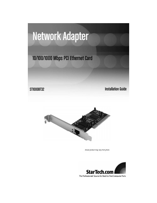
Network Adapter10/100/1000 Mbps PCI Ethernet CardST1000BT32Installation GuideActual product may vary from photoF C C C o m p l i a n c e S t a t e m e n tThis equipment has been tested and found to comply with the limits for a Class B digital device, pursuant to part 15 of the FCC Rules.These limits are designed to provide reasonable protection against harmful interference in a residential installation.This equipment generates, uses and can radiate radio frequency energy and, if not installed and used in accordance with the instructions, may cause harmful interference to radio communications.However, there is no guarantee that interference will not occur in a particular installation.If this equipment does cause harmful interference to radio or television reception, which can be determined by turning the equipment off and on, the user is encouraged to try to correct the interference by one or more of the following measures:• Reorient or relocate the receiving antenna.• Increase the separation between the equipment and receiver.• Connect the equipment into an outlet on a circuit different from that to which the receiver is connected.• Consult the dealer or an experienced radio/TV technician for help.U s e o f T r a d e m a r k s,R e g i s t e r e d T r a d e m a r k s,a n do t h e r P r o t e c t e d N a m e s a n d S y m b o l sThis manual may make reference to trademarks, registered trademarks, and other protected names and/or symbols of third-party companies not related in any way to .Where they occur these references are for illustrative purposes only and do not represent an endorsement of a product or service by , or an endorsement of the product(s) to which this manual applies by the third-party company in question.Regardless of any direct acknowledgement elsewhere in the body of this document, hereby acknowledges that all trademarks, registered trademarks, service marks, and other protected names and/or symbols contained in this manual and related documents are the property of their respective holders.Instruction ManualT a b l e o f C o n t e n t sIntroduction . . . . . . . . . . . . . . . . . . . . . . . . . . . . . . . . . . . . . . . . . . . . . . . . . . . .1 Installation . . . . . . . . . . . . . . . . . . . . . . . . . . . . . . . . . . . . . . . . . . . . . . . . . . . . .2 Connecting Your Card to a Network . . . . . . . . . . . . . . . . . . . . . . . . . . . . . . . . .2 Installing the Drivers . . . . . . . . . . . . . . . . . . . . . . . . . . . . . . . . . . . . . . . . . . . . .3 Verifying driver installation . . . . . . . . . . . . . . . . . . . . . . . . . . . . . . . . . . . . . . . .3 Monitoring Your Card . . . . . . . . . . . . . . . . . . . . . . . . . . . . . . . . . . . . . . . . . . . . .4 Tips for Setting Up Your Network . . . . . . . . . . . . . . . . . . . . . . . . . . . . . . . . . . .4 Specifications . . . . . . . . . . . . . . . . . . . . . . . . . . . . . . . . . . . . . . . . . . . . . . . . . . .6 Accessory products from . . . . . . . . . . . . . . . . . . . . . . . . . . . . .6 Technical Support . . . . . . . . . . . . . . . . . . . . . . . . . . . . . . . . . . . . . . . . . . . . . . .7 Warranty Information . . . . . . . . . . . . . . . . . . . . . . . . . . . . . . . . . . . . . . . . . . . . .7iInstruction ManualI n t r o d u c t i o nThank you for purchasing a 110/100/1000 Mbps PCI Ethernet Card. Featuring Auto-Negotiation capability and support for data transmission bandwidth up to 2000Mbits/sec, the card is easy to install and set up, and is fully Plug and Play compatible in a wide range of operating environments.Features•Automatically configures IRQ and I/O addresses•T wo LEDs indicate network link/activity and 10/100 or 1000Mbps selection.•Supports 32-bit PCI Bus Master for high performance and low processor utilization •Supports early interrupt on transmit for increased performance•Supports 32-bit 33/66MHz PCI Local Bus Master for high-speed operationBefore You BeginSystem Requirements•An IBM compatible notebook computer with a Pentium-based processor•An open PCI slot•One of the following operating environments:Windows Vista/XP/ME/2000/98, Windows NT, Linux, NetWare 3.x/4.x, Lan Manager, TCP/IP softwareContentsThis package should contain:• 1 x PCI Ethernet Adapter card• 1 x Driver disk• 1 x Installation Guide1Instruction Manual I n s t a l l a t i o nInstruction Manual, which willInstruction ManualInstruction Manual2.Double-click Local Area Connections and click the Properties button.Windows Me/981.Click on Start, then Settings, then Control Panel.2.Double-click on Network.NOTE:If you need to add any of the following components, check your Windows documentation for details.Make sure all your computers are on the same workgroupT o be able to communicate properly with each other, each computer must be located on the same workgroup.Each computer within a workgroup must have a unique name.T o ensure compatiblility between each version of Windows, keep your computer names under 13 characters long.To view, add, or edit your computer’s name, do the following: Windows XP1.Click Start and then Control Panel.2.Double-click System then click on the computer name tab.Windows 20001.Click on Start, then Settings, then Control Panel.2.Double-click on System.3.Click on the Network Identification tab.Windows ME/98/1.Click Start, then Settings, then Control Panel.2.Double-click Network, then click the Identification tab.Make Sure Your Sharing is Set Up Properly1.Go to your network dialog box using the procedure explained under “Make sureyour computers are configured properly.”2.Click on File and Print Sharing.5Instruction ManualInstruction ManualT e c h n i c a l S u p p o r t’s lifetime technical support is an integral part of our commitment to provide industry-leading solutions.If you ever need help with your product, visit/support and access our comprehensive selection of online tools, documentation, and downloads.W a r r a n t y I n f o r m a t i o nThis product is backed by a lifetime warranty.In addition, warrants its products against defects in materials and workmanship for the periods noted, following the initial date of purchase.During this period, the products may be returned for repair, or replacement with equivalent products at our discretion.The warranty covers parts and labor costs does not warrant its products from defects or damages arising from misuse, abuse, alteration, or normal wear and tear.Limitation of LiabilityIn no event shall the liability of Ltd.and USA LLP (or their officers, directors, employees or agents) for any damages (whether direct or indirect, special, punitive, incidental, consequential, or otherwise), loss of profits, loss of business, or any pecuniary loss, arising out of or related to the use of the product exceed the actual price paid for the product.Some states do not allow the exclusion or limitation of incidental or consequential damages.If such laws apply, the limitations or exclusions contained in this statement may not apply to you.7A b o u t S t a r T e c h.c o m is “The Professionals’Source for Hard-to-Find ComputerParts”.Since 1985, we have been providing IT professionals with thequality products they need to complete their solutions.We offer anunmatched selection of computer parts, cables, server managementsolutions and A/V products and serve a worldwide market through ourlocations in the United States, Canada, the United Kingdom and Taiwan.Visit for complete information about all our productsand to access exclusive interactive tools such as the Parts Finder and theKVM Reference makes it easy to complete almostany IT solution.Find out for yourself why our products lead the industry inperformance, support, and value.Revised:22 October 2007 (Rev.C)。
网络适配器说明书

3、按以上步骤,给分机一个一个接入网络并设置好。 注:此网络适配器的编码即为电梯分机的编码,电梯分机无需再次编码。
二、基本设置:
注:由于设备出厂时默认使用的IP地址相同,初次安装时,请不要同时接入多台没有修改IP的设备到网络中,以免网络冲 突。将分机插上网络并通电,待分机启动完毕后,(首次启动)系统自动显示“基本设置(必填)”界面:可在“基 本设置”页面中选择“手动设置网络”或“全自动设置网络”两种方式给分机设置信息,方法如下:
网络适配器ຫໍສະໝຸດ 1网络适配器一、侧面接口说明: 侧面接口图
黄黄
COM 1
机房分机
轿厢分机
1、电源(DC12-18V):插入附送的电源(14V/0.8A),为每部电梯的电梯机房、电梯轿厢、电梯顶部、电梯底部的 分机供电。
2、网口(LAN):将网络适配器的网络接口通过一根网线插入路由器LAN端(或交换机)任一端口,接上电源,直到网 络适配器状态指示灯慢闪时,即表示启动正常。
3、接分机端:有2组“1、COM”接线柱,功能接口相同,可接轿厢分机和机房分机。即:将轿厢分机的两芯引线(黄、
网络适配器
2
黄线)和机房分机的“1、COM”接线柱全部并接到一条两芯总线上后,再与总线适配器的“1、COM”接线柱相连 (不分极性)。 4、复位键(RST):联网的情况下,按一下“RST”复位按键松开,可播报该网络适配器的IP地址;长按“RST”键约 5~6秒,可自动恢复出厂设置。 5、报警输出接口(ARM+、ARM-):可外接报警闪灯、喇叭等报警设备。分机向主机报警的时候,端口上有报警信号 h输出(12V/500mA)。 6、联动开关接口(常开no、常闭nc):分机向主机报警的时候,端口上有开关量输出(注:该端口最大负载12V/3A)。 7、对讲指示灯:主机选中分机对讲时或者主机广播时,绿灯常亮。 8、状态指示灯:待机时红灯闪亮,呼叫时红灯常亮。 9、本梯指示灯:接电源接口接了电源,本梯指示灯亮;如灯不亮,说明电源供电不正常。
信锐产品 T4 套件 AP 安装手册说明书
T4套件产品安装指导深圳市信锐网科技术有限公司文档版本:00T400-001805-01版权所有 © 深圳市信锐网科技术有限公司 2015.保留一切权利。
1产品概述T4 套件支架所支持的AP外观如下图。
各型号AP参数详见信锐官网。
后续新产品使用T4 支架,但外观或接口上可能有所变化,请以实物图为准。
图 1-1产品正面图图 1-2产品侧面接口图2安装准备2.1 安全注意事项T4套件支架所支持的AP为室内型,必须在室内使用,为保证AP设备长期处于良好的运行状态,保证设备能正常工作及延长使用寿命,必须使系统处于规定的运行环境之中。
警告:为了避免对人和设备造成伤害,请在安装设备之前仔细阅读本书的安全建议。
请在专业的工程人员指导下安装设备,以下安全建议并不涉及所有可能出现的危险情况。
2.1.1安装选址✓选址不宜在温度高、有害气体、易燃易爆、易受电磁干扰(大型雷达站、发射电台、变电站)及电压不稳的环境中;应避开经常有大震动或强噪声且远离各种污染源的地方。
✓安装地应该干燥,避免安装在直接雨淋、易被溅水、易积水、渗水、滴漏、结露等地方。
✓在进行工程设计时,应根据通信网络规划和通信设备的技术要求,综合考虑水文、地质、地震、电力、交通等因素,选择符合通信设备工程环境设计要求的地址。
2.1.2温度、湿度要求设备工作的温度、湿度要求如下:项目参数范围工作温度-10℃~55℃存储温度-40℃~70℃工作湿度5%~95%(非凝结)存储湿度5%~95%(非凝结)2.2 安装工具进行室内型AP设备的安装以及调试工作,在进行到不同的阶段需要准备不同的工具与仪表。
请事先自行准备做好工具和仪表,以免在工作现场延误时间。
(本司不提供以下工具,请用户自备)2.3 物料准备安装支架为标配,里面包含塑料膨胀管、膨胀螺钉、普通螺丝,此安装支架可以壁挂安装也可以吸顶安装天花板上;关联产品需要自行准备。
壁挂、吸顶安装时涉及到的工程物料如下:关联产品如下:3产品安装3.1 安装流程T4 套件支架所支持的AP仅适用于室内安装,支持以下安装方式:吸顶安装方式、壁挂安装方式、桌面放装方式。
无线宽带客户端产品使用手册

无线宽带客户端产品使用手册中国电信无线宽带客户端使用手册中国电信股份有限公司2008-10一、无线宽带客户端介绍中国电信无线宽带客户端是中国电信为您提供的网络接入客户端。
您可以通过该客户端实现ADSL、WLAN、CDMA网络接入。
二、安装无线宽带客户端软件与数据卡驱动1.使用申请无线宽带业务时获得的光盘进行安装。
选择安装无线宽带客户端。
2.接受协议条款,进入快速安装进程:选择“我同意,我接受以上协议的所有条款”,单击<下一步>按钮,进入下一步。
说明:选择“进行快速安装”将把客户端程序安装在默认路径下,否则请根据向导设置安装路径和程序图标位置。
3.选择安装类型初次安装请选择默认安装方式“完全安装”,单击<下一步>,进入安装进程。
若新安装版本较低,将退出安装程序,如下图:说明:若更新数据卡驱动请选择“仅安装数据卡驱动程序”,单击<下一步>,进入数据卡驱动程序安装进程。
4.安装完成安装完毕,出现如下画面:单击<完成>按钮,完成无线宽带客户端的安装。
如果您希望在windows启动时自动运行无线宽带客户端请在此设置。
三、无线宽带客户端界面简介1.主界面介绍页面选择菜单项相应网络与当前信号强度网络接入操作按钮当前优选网络推荐2.快捷图标中国电信无线宽带客户端提供的快捷图标如下表所示:快捷图标说明•打开“拨号连接”页面•打开“CDMA应用”页面3.状态信息拨号连接的显示状态信息如下表所示:状态信息说明ADSL/LAN 拨号连接状态•:已连接有线宽带网络•:未连接有线宽带网络电信WiFi 网络信号(包括电信热点/家庭无线/其他无线)•:WiFi网络信号强度•:无WiFi网络信号强度CDMA网络信号•:CDMA网络信号强度•:无CDMA网络信号强度四、网络接入服务1.客户端登录当您第一次启动无线宽带客户端时,软件将提示您设置ADSL与电信WiFi接入帐号和密码,输入后正常启动客户端。
天翼宽带客户端产品使用说明书

中国电信天翼宽带客户端使用手册中国电信天翼宽带客户端使用手册目录一、天翼宽带客户端介绍 (2)二、天翼宽带客户端安装说明 (2)1. 插入上网卡会自动弹出图1 的界面 (2)2. 准备安装 (2)3. 进入协议条款界面 (3)4. 选择安装目录 (3)5. 完成安装 (5)三、天翼宽带客户端界面简介 (5)1. 主界面介绍 (5)2. 状态信息 (6)3. 基础应用按钮信息 (6)4. 菜单按钮信息 (7)5. 客户端界面切换信息 (7)四、通行证管理 (8)1. 注册通行证 (8)2. 找回通行证 (10)3. 通行证应用 (10)五、网络接入服务 (10)1.天翼宽带(WiFi)接入 (10)2.天翼宽带(3G)接入 (11)3.天翼宽带(1X)接入 (11)4.自动连接 (11)5.有线连接 (11)6.家庭无线连接 (12)六、天翼宽带客户端基础应用功能 (12)1. 设置功能 (12)2. “查看”功能 (14)3. “帮助”功能 (15)4. “短信”应用 (16)5. “通讯录”应用 (19)6. “网盘”应用 (20)七、天翼宽带客户端扩展应用功能加载 (22)1. 全部应用 (22)2. 电信推荐应用 (22)3. 已安装应用 (23)4. 热门应用 (24)5. 快速查找 (24)一、天翼宽带客户端介绍“天翼宽带客户端”是中国电信为您提供的宽带接入和应用集成软件,可对中国电信天翼宽带(WiFi)、天翼宽带(3G)、天翼宽带(1X)以及有线宽带网络进行接入,为您提供“无处不在”的网络接入能力,并通过集成简便实用的多种应用带给您“无所不能”的应用感知。
说明:1.您需要连接天翼宽带(WiFi)网络时,请确认使用了配置有符合802.11b/g标准功能模块或设备的计算机。
2.该版本客户端仅支持Windows XP、Windows Vista、Windows 7 32位的中文简体操作系统。
客户端下载安装说明

客户端下载安装说明【客户端下载安装说明】尊敬的用户,感谢您选择使用我们的客户端。
为了便于您顺利完成下载和安装过程,我们特别为您提供详细的下载安装说明。
请您耐心阅读以下内容:一、下载准备1. 您需要确保您的设备已经连接到互联网。
2. 客户端的下载文件较大,请确保您的设备有足够的存储空间。
3. 请确保您的设备具备兼容性,以避免出现不兼容或不能正常运行的情况。
二、下载客户端1. 打开您的浏览器,进入我们的官方网站。
2. 在主页上找到并点击“下载”按钮,这将会跳转至下载页面。
3. 您可以在下载页面中找到客户端的下载链接,点击链接即可开始下载。
三、安装客户端1. 下载完成后,找到下载文件并点击打开。
2. 根据设备的操作系统类型,选择执行对应的安装程序。
3. 在安装过程中,请按照提示完成操作,并仔细阅读用户许可协议。
4. 若需要,可以选择自定义安装路径或其他相关选项。
5. 等待安装过程完成,不要中途关闭安装程序。
四、启动客户端1. 安装完成后,您可以在桌面或开始菜单中找到客户端的图标。
2. 双击客户端图标启动程序。
3. 如果客户端需要登录,请使用您的账号和密码进行登录。
五、常见问题解决如果您在下载和安装过程中遇到任何问题,我们建议您参考以下几点进行排查:1. 确保您的网络连接正常,并且信号强度良好。
2. 检查您的设备存储空间是否足够,如果不足,请释放空间后重试。
3. 确保您的设备操作系统已经更新至最新版本。
4. 可尝试重新下载和安装客户端。
六、联系我们如果您在下载和安装过程中仍然遇到问题,欢迎您与我们的客户服务团队联系。
您可以通过以下方式与我们取得联系:1. 发送电子邮件至我们的客户服务邮箱,我们将尽快回复您的问题。
2. 拨打我们的客户服务电话,我们的工作人员将为您提供专业的技术支持。
以上就是我们客户端下载安装的详细说明。
希望这些信息对您有所帮助。
感谢您的支持与信任,如果您对我们的客户端有任何建议或意见,请随时与我们联系。
e8-B终端用户使用手册(ZXV10 H608B)

在上图所示的指示灯说明页面中,状态指示正确后,单击继续按钮,弹出 检查设备连接情况页面。安装程序将自动检测 e8-B 终端与计算机的连接情况, 检测通过后,将弹出如下图所示的通过信息。
10
第 4 章 用户配置使用说明
4.1.10 修改计算机配置
为了使 e8-B 终端与计算机正常连接,安装程序将自动修改您的计算机的配 置,启动 DHCP 功能,配置完成后,弹出如下图所示的修改计算机配置页面。
12
第 4 章 用户配置使用说明
下角的说明设置新的 ESSID 和 WPA 密钥,ESSID 由不可修改的前缀“ChinaNet-” 和 0~23 位可编辑的字符两部分组成,您可以将后一部分设置为便于记忆的名称 或标识,如家人的生日或家里固定电话号码等,但请记住该 ESSID 和 WPA 密 钥,在错误!未找到引用源。节设置您的无线网卡时必须设置和此处相同的 ESSID 和 WPA 密钥。
件。
请勿将本产品放置在接近热源或高温的地方,应避免阳光直接曝晒。 请勿将本产品放置在过于潮湿或接近水源的地方。切勿让任何液体泄漏
到本产品上。
推荐您使用安装光盘进行安装配置操作。
使用
断开电源后,至少需要等待 15 秒,才能再次接通电源。 请保持散热孔通畅,切勿将任何物品遮挡住设备的散热孔。 保持设备通风、电源插头清洁干燥、如有不正常现象出现(冒烟/声音异
3.2 后面板及端口使用说明
e8-B 终端的后面板上有接口和按键,各接口和按键说明如下表所示。
标识 POWER
端口/按键名称 电源接口
说明 与原厂配置的电源适配器连接,引入直流电源
On/Off
Hale Waihona Puke 电源开关接通或断开设备电源
三大运营商3G无线宽带客户端安装说明

注意事项及常见问题解决
❤电信套餐上超后为0.05元/分钟,也就是3元一小时。
❤移动上超后为0.01元/KB,这个上超后很贵
❤联通上超后为0.1元/MB
三大运营商3G无线宽带客户端安装说明
/help/how2install.htm
电信天翼3G无线宽带ቤተ መጻሕፍቲ ባይዱ户端安装说明
1)插入网卡后会在我的电脑里多出一个虚拟光驱,如图1
2)如电脑没有自动运行安装文件,可打开虚拟光驱盘符自行运行安装文件,如图
其他设备安装文件大同小异
4)上网卡没用到一年就欠费?
电信上网卡有两种扣费方式,一种是这个月上超后在下个月的月初会停机,客户需要把上个月上超的费用补上才能继续使用,第二种是上超后会在后续余额里扣费,这样客户就用不到全年的费用就用完余额。
无线宽带客户端是中国电信为您提供的网络接入客户端,您可以使用本客户端通过中国电信无线宽带(WiFi)或天翼网络接入中国电信无线宽带互联网。
3.联通因为流量比较少,请注意查看流量
1)有的客户上网的时候会发生掉线,一般一个小时掉线的话属于正常情况。如果掉线频繁,就不正常了。
解决办法:出现这种情况的话原因比较多,系统的问题,信号问题,设备问题,都会引起掉线,我们可以使用排除发进行判断,先换个电脑试试,如果换个电脑没有问题的话,说明您的电脑系统有问题,请查杀一下病毒。如果换电脑试的话还是掉线的话,请换到窗边离户外近的位置使用一下。两个办法还不行的话可以断定是设备的问题,请找购买商测试,如有问题可更换或维修。
页尾
1.电信上网卡在不上网的时候记得要点开无线宽带界面断开连接,查询使用时间在拨号软件的工具-查询时长里面查询。要是忘记断开关机电信会在大约15分钟后自动断开,这样时间就白白消耗了。先断开在关闭拨号程序再拔下来设备。
新江西移动宽带客户端应用指导手册样本
江西移动宽带客户端应用指导手册一.软件概况................................................... - 1 -二.客户端的安装和使用......................................... - 2 -1.客户端下载................................................ - 2 -2.客户端安装................................................ - 2 -3.客户端介绍及使用.......................................... - 7 -3.1 拨号界面............................................. - 7 -3.2 网速测试界面......................................... - 9 -3.3 故障诊断界面........................................ - 10 -3.4 上网导航界面........................................ - 12 -三.客户端常见设置............................................ - 12 -四常见问题解决(F&Q)........................................... - 14 -一.软件概况江西移动宽带客户端( 以下简称为客户端) 是为家庭宽带用户提供宽带接入和应用的软件, 该软件集成多个应用功能模块, 能够为宽带用户提供方便、快捷的服务。
说明:1、该版本的客户端仅支持Windows XP、 Windows Vista 、 Windows 7 32位等中文简体操作系统。
- 1、下载文档前请自行甄别文档内容的完整性,平台不提供额外的编辑、内容补充、找答案等附加服务。
- 2、"仅部分预览"的文档,不可在线预览部分如存在完整性等问题,可反馈申请退款(可完整预览的文档不适用该条件!)。
- 3、如文档侵犯您的权益,请联系客服反馈,我们会尽快为您处理(人工客服工作时间:9:00-18:30)。
产品适配器安装使用手册
一、系统安装
备注:本系统安装需相应的配置环境,在安装产品适配器客户端时会自动检测安装机器是否已安装配置环境。
如果计算机上没有安装相应的配置环境,则会先提示安装配置环境(系统配置环境安装向导),如果已安装配置环境,则跳过配置环境安装过程,直接安装安装产品适配器客户端。
A、系统配置环境安装向导:
1、双击安装产品适配器客户端.msi文件,如果本机没有安装环境,
则提示下载配置环境文件,如下图:
图(1)
2、请点击上图(1)中的【是】按钮,到下一步,如下图(2)
图(2)
3、点击上图(2)的【运行】按钮,则下载该环境配置文件,下载
完成后,估计会等待几秒中后提示安装上述下载的文件,如下图(3)
图(3)
4、点击上图(3)中的【运行】按钮,进入下一界面,如图(4)
图(4)
5、点击图(4)中的【下一步】开始安装配置环境,如下图(5)
图(5)
6、选择上图(5)中的【我接收许可协议中的条款】并打钩,点击
【安装】按钮,则开始安装配置环境,如下图(6)
图(6)
7、等待安装完成配置环境,若安装完成,则点击下图(7)中的【完
成】按钮,到此安装配置环境已安装完成。
图(7)
B、安装产品适配器客户端安装向导
1、双击安装产品适配器.msi文件,提示安装安装产品适配器客户端,如下图:
(1)
(2)
(3)
(4)(三)安装结束
(注:文档可能无法思考全面,请浏览后下载,供参考。
可复制、编制,期待你的好评与关注)。
