BL-HZ336G-L8-TRB佰鸿一级代理推荐资料
泊声E68产品说明书
附件一 : FM 电台接收信号增强的几种方法
附件二: FM 天线安装示意图
附件三: MP3 使用注意事项
附件四:安装布线说明
1. backaudio 泊声简介
backaudio 泊声是业界领先的家庭背景音乐品牌,采用美国顶级音频工程设计及 DSP 数 字信号处理技术,系统操作灵活方便,HI-FI 级立体声音质,声音均匀柔和;泊声同时开创 性地提出了中央智能主机的概念,集成了功放阵列和先进的控制系统,拥有该领域多项专利; 凭借优异稳定的性能、卓越的人性化设计理念及优质的服务,泊声家庭背景音乐系统深受顾 客的喜爱和消费者的广泛好评。
2.3.1.产品特点.................................................................................................................. 2 2.4. 标准控制面板使用说明 .................................................................................................. 4 3. 系统安装说明.............................................................................................................................. 4 3.1. 喇叭选型及安装 .............................................................................................................. 4
BL-HUB35A-TRB佰鸿一级代理推荐资料

● DEVICE NUMBER:BL-HUB35A-TRBelectronics.4.General use.● Absolute Maximum Ratings(Ta=25℃)Parameter Symbol Rating UnitPower Dissipation Pd 80 mWForward Current I F 30 mA Peak Forward Current *1I FP 100 mA Reverse Volage V R 5 V Operating Temperature Topr -25℃~80℃-Storage Temperature Tstg -30℃~85℃-Soldering Temperature Tsol See Page 6 -*1 Condition for I FP is pulse of 1/10 duty and 0.1msec width.● Typical Electro-Optical Characteristics Curves Forward current (mA)R e l a t i v e l u m i n o u s i n t e n s i t y (@20m A )F o r w a r d c u r r e n t (m A )1020304050Fig.1 Relative intensity vs. wavelength R e l a t i v e r a d i a n t i n t e n s i t yFig.2 Forward current derating curveTolerance for each Bin limit is ± 15 %●BIN:I n t e n s i t y B I N C O D E●Judgment criteria of failure for the reliabilityMeasuring items Symbol Measuring conditions Judgement criteria for failureUx1.2 Forward voltage V F ( V) I F=20mA OverUx2 Reverse current I R(uA) V R=5V OverSX0.5 Luminous intensity Iv ( mcd ) I F=20mA Below Note: 1.U means the upper limit of specified characteristics. S means initial value.2.Measurment shall be taken between 2 hours and after the test pieces have been returned tonormal ambient conditions after completion of each test.seconds per solder-land is to be observed.2. Reflow SolderingPreheating : 140℃~160℃±5℃,within 2 minutes.3.Preheating : 120℃~150℃,within 120~180 sec.Operation heating : 245℃±5℃within 5 sec.260℃ (Max)Gradual Cooling (Avoid quenching).Time●Handling :Care must be taken not to cause to the epoxy resin portion of BRIGHT LEDs while it is exposed to high temperature.Care must be taken not rub the epoxy resin portion of BRIGHT LEDs with hard or sharp article such as the sand blast and the metal hook.instantaneous voltage at the turning ON and OFF of the circuit. When using the pulse drive care must be taken to keep the average current within the rated figures.Also, the circuit should be designed so as be subjected to reverse voltage when turning off theBRIGHT LEDs. ● Storage:In order to avoid the absorption of moisture, it is recommended to solder BRIGHT LEDs as soon as possible after unpacking the sealed envelope.If the envelope is still packed, to store it in the environment as following: (1) Temperature : 5℃-30℃(41℉)Humidity : RH 60﹪Max.(2) After this bag is opened, devices that will be applied to infrared reflow, vapor-phase reflow, or equivalent soldering process must be: a. Completed within 168 hours.b. Stored at less than 30% RH.(3) Devices require baking before mounting, if: (2) a or (2) b is not met. (4) If baking is required, devices must be baked under below conditions: 48 hours at 60℃±3℃. ● Package and Label of Products: (1) Package: Products are packed in one bag of 3000 pcs (one taping reel) and a label is attached on each bag. (2) Label: BRIGHT LED LOGO Part No. Quantity BIN.Sealing Datexx xx xx Location。
BOMAG 博马双钢轮振动压路机 BW100SL-5 和 BW120SL-5 说明书

TANDEM VIBRATORY ROLLERBW100SL-5 and BW120SL-5/usStandard EquipmentFoldable ROPS with seat beltHydrostatic travel and vibration drive P ressure sprinkler system with interval switch S uspended operator´s platform2 scrapers per drum, spring loaded and tiltable M ulti-function travel leverM ulti-function display incl. operating hour meterW ater levelF uel levelE lectric fuel gaugeE mergency STOPIndividual control, vibrationIntelligent Vibration Control (IVC)I ntegrated stowage compartmentA djustable operator´s seatL ashing eyes, galvanizedB ack-up alarmS ingle point lifting deviceV -belt protectionV andalism protectionL ockable engine hood made of composite materialW orking lights front and rear12V socketS eat contact switchP lastic water tankB olt-on oscillating/articulating jointOptional EquipmentI ndicator and hazard lightsRotary beaconBattery disconnection switchSliding seatECONOMIZERBurglary protectionSpecial paint Technical data BOMAG BOMAG BW 100 SL-5 BW 120 SL-5Weights Operating weight w. ROPS ...............lb (kg) 5181 (2350) 5511 (2500)Average static linear load ............lb/in (kg/cm) 66.1 (11.8) 58.2 (10.4)Driving Characteristics Speed ............................mph (km/h) 0 – 5.6 (0 – 9) 0 – 5.6 (0 – 9)Working speed with vibration .........mph (km/h) 0 – 3.1 (0 – 5) 0 – 3.1 (0 – 5)Max. gradeability without/with vibr. ............% 40 / 30 40 / 30Drive Engine manufacturer .......................... Kubota Kubota Type. . . . . . . . . . . . . . . . . . . . . . . . . . . . . . . . . . . . . . . D 1703-DI D 1703-DI Tier Compliance ............................. Tier 4 Final Tier 4 Final Cooling .................................... water water Number of cylinders .......................... 3 3Performance ISO 14396....................kW 18.5 18.5Performance SAE J 1995 .....................hp 24.8 24.8Speed ..................................rpm 2200 2200Electric equipment ..........................V 12 12Driven drum ................................ front + rear front + rear Brakes Service brake ................................ hydrost. hydrost.Parking brake ................................ hydromec. hydromec.Steering .................................... Steering system ............................... oscil.artic. oscil.artic.Steering method .............................. hydrost. hydrost.Steering / oscillating angle +/- ................deg 32 / 10 32 / 10Crab steer offset – manual ...............in (mm) 0 – 2 (0 – 50) 0 – 2 (0 – 50)Track radius, inner .....................in (mm) 96.5 (2450) 96.5 (2450)Exciter System Vibrating drum .............................. front + rear front + rear Drive system ................................ hydrost. hydrost.Frequency .........................VPM (Hz) 4320 (72) 4320 (72)Amplitude ...........................in (mm) 0.020 (0.50) 0.020 (0.50)Centrifugal force .......................lb (kN) 7640 (34) 8993 (40)Drum Water Spray System Type. . . . . . . . . . . . . . . . . . . . . . . . . . . . . . . . . . . . . . . pressure with interval pressure with interval Capacities Fuel ..................................gal (l) 9.2 (35) 9.2 (35)Water .................................gal (l) 43.6 (165) 43.6 (165)Technical modifications reserved. Machines may be shown with options.Technical DataBW 100 SL-5, BW 120 SL-5A B C D H H2K L O S W BW 100 SL-5694220.627.671.21011099.6 1.40.439.4(1752)(1072)(523)(700)(1808)(2568)(254)(2529)(36)(10)(1000)BW 120 SL-5695020.627.671.21011099.6 1.40.447.2(1752)(1272)(523)(700)(1808)(2568)(254)(2529)(36)(10)(1200)Dimensions in inches (mm)Shipping dimensions in ft 3 (m 3)BW 100 SL-5 247 (7)BW 120 SL-5 293 (8.3)。
XL4005芯龙(XLSEMI)一级代理推荐降压型直流电源变换器芯片(大功率型)
5A 300KHz 32V Buck DC to DC Converter XL4005Featuresn Wide 5V to 32V Input Voltage Range n Output Adjustable from 0.8V to 30Vn Maximum Duty Cycle 100% n Minimum Drop Out 0.6Vn Fixed 300KHz Switching Frequency n 5A Constant Output Current Capability n Internal Optimize Power MOSFET n High efficiencyn Excellent line and load regulation n TTL shutdown capabilityn EN pin with hysteresis functionnBuilt in thermal shutdown function n Built in current limit functionn Built in output short protection function n Available in TO-263 packageApplicationsn LCD Monitor and LCD TV n Digital Photo Frame n Set-up Box n ADSL ModemnTelecom / Networking EquipmentGeneral DescriptionThe XL4005 is a 300KHz fixed frequency PWM buck (step-down) DC/DC converter, capable of driving a 5A load with high efficiency, low ripple and excellent line and load regulation. Requiring a minimum number of external components, the regulator is simple to use and include internal frequency compensation and a fixed-frequency oscillator.The PWM control circuit is able to adjust the duty ratio linearly from 0 to 100%. An enable function, an over current protection function is built inside. When short protection function happens, the operation frequency will be reduced from 300KHz to 60KHz. An internal compensation block is built in to minimize external component count.Figure1. Package Type of XL40055A 300KHz 32V Buck DC to DC ConverterXL4005Pin ConfigurationsFigure2. Pin Configuration of XL4005 (Top View) Table 1 Pin DescriptionPin Number Pin Name Description1 GND Ground Pin. Care must be taken in layout. This pin should be placed outside of the Schottky Diode to output capacitor ground path to prevent switching current spikes from inducing voltage noise into XL4005.2 FB Feedback Pin (FB). Through an external resistor divider network, FB senses the output voltage and regulates it. The feedback threshold voltage is 0.8V.3 SW Power Switch Output Pin (SW). SW is the switch node that supplies power to the output.4 EN Enable Pin. Drive EN pin high to turn on the device, drive it low to turn it off.5 VIN Supply V oltage Input Pin. XL4005 operates from a 5V to 32V DC voltage. Bypass Vin to GND with a suitably large capacitor to eliminate noise on the input.5A 300KHz 32V Buck DC to DC ConverterXL4005Function BlockFigure3. Function Block Diagram of XL4005Typical Application CircuitFigure4. XL4005 Typical Application Circuit 24V~5V/5A5A 300KHz 32V Buck DC to DC Converter XL4005 Ordering InformationOrder Information Marking ID Package Type Packing Type Supplied AsXL4005E1 XL4005E1 TO263-5L 800 Units on Tape & ReelXLSEMI Pb-free products, as designated with “E1” suffix in the par number, are RoHS compliant.Absolute Maximum Ratings(Note1)Parameter Symbol Value Unit Input Voltage Vin -0.3 to 35 V Feedback Pin Voltage V FB-0.3 to Vin VEN Pin Voltage V EN-0.3 to Vin V Output Switch Pin Voltage V Output-0.3 to Vin V Power Dissipation P D Internally limited mW Thermal Resistance (TO263)R JA30 ºC/W (Junction to Ambient, No Heatsink, Free Air)Operating Junction Temperature T J-40 to 125 ºC Storage Temperature T STG-65 to 150 ºC Lead Temperature (Soldering, 10 sec) T LEAD260 ºC ESD (HBM) 2000 V Note1: Stresses greater than those listed under Maximum Ratings may cause permanent damage to the device. This is a stress rating only and functional operation of the device at these or any other conditions above those indicated in the operation is not implied. Exposure to absolute maximum rating conditions for extended periods may affect reliability.5A 300KHz 32V Buck DC to DC Converter XL4005 XL4005 Electrical CharacteristicsT a = 25℃;unless otherwise specified.Symbol Parameter Test Condition Min. Typ. Max. Unit System parameters test circuit figure4VFB FeedbackV oltageVin = 5V to 32V, V out=5VIload=0.5A to 5A0.776 0.8 0.824 VEfficiency ŋVin=12V ,V out=5VIout=5A- 90 - %Electrical Characteristics (DC Parameters)Vin = 12V, GND=0V, Vin & GND parallel connect a 220uf/50V capacitor; Iout=500mA, T a = 25℃; the others floating unless otherwise specified.Parameters Symbol Test Condition Min. Typ. Max. Unit Input operation voltage Vin 5 32 V Shutdown Supply Current I STBY V EN=0V 60 200 uAQuiescent Supply Current I q V EN =2V,V FB =Vin3 5 mAOscillator Frequency Fosc 240 300 360 Khz Switch Current Limit I L V FB =0 8 AEN Pin Threshold V EN High (Regulator ON)Low (Regulator OFF)1.40.8VI H V EN =2V (ON) 1 15 uA EN Pin Input LeakageCurrent ILV EN =0V (OFF) 1 15 uA Max. Duty Cycle D MAX V FB=0V 100 %5A 300KHz 32V Buck DC to DC Converter XL4005 Test Circuit and Layout guidelinesFigure5. Standard Test Circuits and Layout GuidesSelect R1 to be approximately 2K, use a 1% resistor for best stability.C1 and CFF are optional; in order to increase stability and reduce the input power line noise, CIN and C1 must be placed near to VIN and GND;For output voltages greater than approximately 10V, an additional capacitor CFF is required. The compensation capacitor is typically between 100 pf and 33 nf, and is wired in parallel with the output voltage setting resistor, R2. It provides additional stability for high output voltage, low input-output voltages, and/or very low ESR output capacitors, such as solid tantalum capacitors. CFF=1/(31*1000*R2); This capacitor type can be ceramic, plastic, silver mica, etc. (Because of the unstable characteristics of ceramic capacitors made with Z5U material, they are not recommended.)5A 300KHz 32V Buck DC to DC Converter XL4005 Schottky Diode Selection TableCurrent SurfaceMount ThroughHoleVR (The same as system maximum input voltage)20V 30V 40V 50V 60V1A √1N5817 1N5818 1N5819√1N5820 1N5821 1N5822√MBR320 MBR330 MBR340 MBR350 MBR360 √SK32 SK33 SK34 SK35 SK36√30WQ03 30WQ04 30WQ05√31DQ03 31DQ04 31DQ053A√SR302 SR303 SR304 SR305 SR306√1N5823 1N5824 1N5825√SR502 SR503 SR504 SR505 SR506√SB520 SB530 SB540 SB550 SB560 5A√50WQ03 50WQ04 50WQ055A 300KHz 32V Buck DC to DC Converter XL4005 Typical System Application for 24V ~ 12V/4A VersionFigure6. XL4005 System Parameters Test Circuit (24V ~ 12V/4A)Typical System Application for 24V ~ 5V/5AFigure7. XL4005 System Parameters Test Circuit (24V ~ 5V/5A)5A 300KHz 32V Buck DC to DC Converter XL4005Package InformationTO263-5L。
LED 各个厂家对比型号
序类别颜色尺寸品牌品名1 0603按键灯白1.6*0.8* 0.4亿光GT-1972 0603按键灯蓝1.6*0.8* 0.4亿光19-217/BHC-AN1P2/3T3 0603按键灯蓝1.6*0.8* 0.4亿光19-217/BHC-ZL1M2RY/3T4 0603按键灯红1.6*0.8* 0.4亿光19-217/R6C-AL1M2VY/3T5 0603按键灯黄绿1.6*0.8* 0.4亿光19-217/G7C-AL1M2VY/3T6 0603按键灯黄1.6*0.8* 0.4亿光19-217/Y5C-AP1Q2/3T7 0603按键灯橙1.6*0.8* 0.4亿光19-217/S2C-AM2N2VY/3T8 0603按键灯白1.6*0.8*0.3亿光19-218UWD/S327/TR89 0603按键灯蓝1.6*0.8*0.3亿光19-218BHC/ZL1M2QY/TR810 0603侧灯白1.7*1.1*0.6亿光27-21/W1D-ANPHY/3C11 0603侧灯红1.7*1.1*0.6亿光27-21/R6C-AM2N2LY/3C12 0603侧灯红1.7*1.1*0.6亿光27-21/R6C-AN2Q1B-3D13 0603侧灯黄1.7*1.1*0.6亿光27-21/Y2C-CPQB/3C14 0603侧灯绿1.7*1.1*0.6亿光27-21/G6C-AL2N1B/3C15 0603侧灯蓝1.7*1.1*0.6亿光27-21/BHC-AN1P2/3C16 0603侧灯黄绿1.7*1.1*0.6亿光27-21SYGC/S530-E3/TR817 0603侧灯橙红1.7*1.1*0.6亿光27-21/S2C-FP1Q1L/3C18 0802侧灯白2.1*1.0*0.6亿光12-215/W1D-ANPHY/3C19 0802侧灯蓝2.1*1.0*0.6亿光12-215/BHC-2LMRY/3C20 0802侧灯橙2.1*1.0*0.6亿光12-215UYOC/S530-A2/TR821 0802侧灯黄2.1*1.0*0.6亿光12-215UYC-S530-A3-TR822 0802侧灯绿2.1*1.0*0.6亿光12-215/G6C-BP1Q2L/3C23 0802侧灯红2.1*1.0*0.6亿光12-215/SURC-S530-A2/TR824 0802侧灯黄绿2.1*1.0*0.6亿光12-215/SYGC-S530-E2/TR825 0802侧灯橙黄2.1*1.0*0.6亿光12-215UYOC/S530-XX/TR826 0402正灯红1.0*0.5*0.45亿光16-213SURC/S530-A5/TR27 0402正灯蓝1.0*0.5*0.45亿光16-213/BHC-AN1P2/3T28 0402正灯黄绿1.0*0.5*0.45亿光16-213/YGC/S530-E5/TR829 0402正灯翠绿1.0*0.5*0.45亿光16-213/GHC-YR1S1/3T30正发七彩七彩灯1.6*1.6*0.35亿光19-237-R6GHBHC-A01-2T31正发七彩七彩灯1.6*1.6*0.35亿光19-337-R6GHBHC-A01-2T32侧发七彩七彩灯3.0*1.0*1.5亿光12-23C-R6GHBHC-A01-2C33侧白灯白3.5*3.5*0.8亿光47-23UWD/TR834侧白灯白1.8*1.1*0.3亿光48-213/T7D-AQ1R2QY/3C35 3020正白灯侧白灯3.0*2.0*1.3亿光45-11UTC-XXX-TR836 020侧白灯白3.8*1.2*0.6亿光99-216UFC/XXXXXXX/TRB37 335侧白灯白4.0*1.4*0.8亿光99-215/B5-3/T-238 3528闪光灯白3.5*2.8*1.9亿光67-11-W1C-GP2R1B2Z-2T(1芯2脚)39 3228闪光灯白3.2*3.2*0.8亿光67-235-UTC-S734-TR840 3528闪光灯白3.5*2.8*1.8亿光67-23UWC-S400-X9-S612-1-TR8(3芯4脚)41 5050闪光灯白5.0*5.0*1.5亿光59-14UWD-TR8手机用大功率白2.0*1.6*0.9亿光EHP-C04/UT01-P011 0603按键灯白色1.6*0.8*0.4诠兴SP0603B-WW2 0603按键灯暖白1.6*0.8*0.4诠兴SP0603B-WH3 0603按键灯蓝1.6*0.8*0.4诠兴SP0603B-BN4 0603按键灯蓝1.6*0.8*0.4诠兴SP0603B-BH5 0603按键灯橘1.6*0.8*0.4诠兴SP0603B-ON6 0603按键灯黄绿1.6*0.8*0.4诠兴SP0603B-YG7 0603按键灯绿1.6*0.8*0.4诠兴SP0603B-GN8 0603按键灯黄1.6*0.8*0.4诠兴SP0603B-YN9 0603按键灯红1.6*0.8*0.4诠兴SP0603B-RN10正发七彩灯七彩灯3.2*2.8*1.9诠兴SL1411C-3C11侧发七彩灯七彩灯1.6*1.25*0.4诠兴SP372SA-3C12 1204 7彩燈3.2*1.0*1.5诠兴SP1204A-3C13正发白3.2*1.0*1.5诠兴SP1204B-WW14 3528闪光灯白3.5*2.8*1.9诠兴SL1411A-WW(1芯2脚)15 3528闪光灯白3.2*2.8*1.9诠兴SL1411C-WW(3芯4脚)16 3020正灯正向發光LED白3.0*2.0*1.0诠兴SL455SA-WW17 002侧发光側面發光LED白灯3.8*1.2*0.6诠兴SL002SA-WW18 008侧发光側面發光LED白灯4.0*1.4*0.8诠兴SL008SA-WW19 5050七彩灯5.5*5.0*1.6诠兴SL5050A-3C20 5050闪光灯白5.5*5.0*1.6诠兴SL5050A-WW21 5050闪光灯暖白5.5*5.0*1.6诠兴SL5050A-WR1按键灯蓝1.6*0.8* 0.4佰鸿BL-HB336G-TRB2按键灯白1.6*0.8* 0.4佰鸿BL-HZ336G-L8-TRB3按键灯红1.6*0.8* 0.4佰鸿BL-HUB36G-AV-TRB4按键灯橘红1.6*0.8* 0.4佰鸿BL-HJE36G-AV-TRB5按键灯黄/琥珀1.6*0.8* 0.4佰鸿BL-HKC36G-AV-TRB6按键灯黄绿1.6*0.8* 0.4佰鸿BL-HGE36G-AV-TRB7按键灯翠绿1.6*0.8* 0.4佰鸿BL-HG836G-AV-TRB8按键灯翠绿1.6*0.8* 0.6佰鸿BL-HGK36A-AV-TRB9 0802侧灯蓝2.1*1.0*0.6佰鸿BL-HB334E-TRB10 0802侧灯黄2.1*1.0*0.6佰鸿BL-HKC34E-AV-TRB11 0802侧灯橙2.1*1.0*0.6佰鸿BL-HJE34E--AV-TRB12 0802侧灯白2.1*1.0*0.6佰鸿BL-HZ334E-L11-TRB13 0802侧灯红2.1*1.0*0.6佰鸿BL-HUB34E-AV-TRB14侧发七彩灯七彩3.0*1.0*1.5佰鸿"BL-HJEGKB534S-TRBBL-HJEG8B534S-TRB "15正发七彩灯七彩1.8*1.8*0.35佰鸿BL-HJEGKBE36T-TRB16 3020闪光灯白3.0*2.0*1.3佰鸿BL-HZD-32Y-TRB17 335闪光灯白4.0*1.4*0.8佰鸿BZ-HZD39B-LWB-TRB18 020闪光灯白1.2*1.9*0.6佰鸿BZ-HZD39D-LWB-TRB19 3528闪光灯白3.5*2.8*1.9佰鸿BZ-HZD32X-LWB-TRB(1芯2脚)20 5050闪光灯白5.0*5.0*1.5佰鸿BL-HZD39F-TRB(8脚)21 5050闪光灯白5.0*5.0*1.5佰鸿BZ-H3ZD32L-A-LWB-TRB(6脚)1 0603按键灯1.6*0.8* 0.4AOT AOT-0603P-W310H2 0603按键灯蓝灯1.6*0.8* 0.4AOT AOT-0603BL31A-NO-N-33 0603按键灯琥珀/橙灯)1.6*0.8* 0.4AOT AOT-0603AM31A-NO-N-34 0603按键灯蓝灯1.6*0.8* 0.4AOT AOT-0603BS31A-NO-N-35 0603按键灯翠绿1.6*0.8* 0.4AOT AOT-0603GS31A-ZO-N-36 604按键灯翠绿1.6*0.8* 0.4AOT A0T-0603P-G01-Z-H07 0603按键灯红灯1.6*0.8* 0.4AOT AOT-0603RE31A-NO-N-38 0603按键灯黄灯1.6*0.8* 0.4AOT AOT-0603YL31A-NO-N-39 0603按键灯黄绿灯1.6*0.8* 0.4AOT AOT-0603YG31A-NO-N-310 0603按键灯白灯1.6*0.8* 0.4AOT AOT-0603W331A-NO-X-311 0603按键灯紫灯1.6*0.8* 0.4AOT AOT-0603VTD1A-N00-X-312 0603按键灯粉红色1.6*0.8* 0.4AOT AOT-0603PKD1A-N00-X-313 1615正发七彩灯七彩灯1.6*1.5*0.5 AOT AOT-1615-3D-RGB01-Z14 1204侧发七彩灯七彩灯3.2*1.0*1.5 AOT AOT-1204-3D-RGB03-H15 1204侧发七彩灯七彩灯3.0*1.0*1.5 AOT AOT-1204RGB73A-N1-N-3-M 16七彩灯1.6*1.5*0.5 AOT AOT-1615RGB43A-Z0-N-317 3228七彩灯七彩灯3.2*2.8*1.9 AOT AOT-3228RGB43C-Z018 3528闪光灯白3.5*2.8*1.85 AOT AOT-3228-HPW-0303B-H(3芯4脚)19 3228闪光灯白3.2*2.8*1.2 AOT AOT-3228MINI-0452BZ-H(超薄)20 3228紫灯紫外3.2*2.8*1.85 AOT AOT-3228UV21B-Z021 3020闪光灯侧发LED 3.0*2.0*1.3 AOT AOT-3020PW21B-ZO-L-122 3020闪光灯侧发LED 3.0*2.0*1.3 AOT AOT-3020BLW-0201-Z-2-Y23 3806侧白灯侧发LED 3.8*0.6*1.2 AOT AOT-3806PW21B-Z10-X-324 5050闪光灯白5.0*5.0*1.5 AOT AOT-5050HPW-0203BR-Z-H(6脚) 25背光LED 3.8*1.0*0.42 AOT AOT-AEKWU26 3.3*3.3*1.5 AOT AOT-3333HPW-0203BR-H1 0603按键灯白1.6*0.8* 0.4光宝LTW-C193TS5-5A2 0603按键灯蓝1.6*0.8* 0.4光宝LTST-C193TBKT-5A3 0603按键灯黄绿1.6*0.8* 0.4光宝LTST-C193KGKT-5A-3544 0603按键灯红1.6*0.8* 0.4光宝LTST-C193KRKT-5A-3545 0603按键灯翠绿1.6*0.8* 0.4光宝LTST-C193JGKT-5A-3546侧发七彩灯七彩3.0*1.0*2.0光宝LTST-S32F1KT-5A7正发七彩灯七彩2.1*1.6*0.4光宝LTST-C19GD2WT-G1 3.8*1.2*0.6宏齐HT-V106SW-AA12蓝色1.6x1.0x0.6宏齐HT-121BP3七彩3.2x1.5x1.0宏齐HT-311FCH4白色3.5*2.7*1.8宏齐HT-T368BPF5白色3.5*2.7*1.8宏齐HT-U169TW6白色3.2*2.7*0.8宏齐HT-V253BPK7白色1.6x1.5x0.55宏齐HT-261USD/UYG。
河南佰鸿生物科技有限公司介绍企业发展分析报告
Enterprise Development专业品质权威Analysis Report企业发展分析报告河南佰鸿生物科技有限公司免责声明:本报告通过对该企业公开数据进行分析生成,并不完全代表我方对该企业的意见,如有错误请及时联系;本报告出于对企业发展研究目的产生,仅供参考,在任何情况下,使用本报告所引起的一切后果,我方不承担任何责任:本报告不得用于一切商业用途,如需引用或合作,请与我方联系:河南佰鸿生物科技有限公司1企业发展分析结果1.1 企业发展指数得分企业发展指数得分河南佰鸿生物科技有限公司综合得分说明:企业发展指数根据企业规模、企业创新、企业风险、企业活力四个维度对企业发展情况进行评价。
该企业的综合评价得分需要您得到该公司授权后,我们将协助您分析给出。
1.2 企业画像类别内容行业空资质空产品服务、三类医疗器械销售、维修及租赁;销售:仪器1.3 发展历程2工商2.1工商信息2.2工商变更2.3股东结构2.4主要人员2.5分支机构2.6对外投资2.7企业年报2.8股权出质2.9动产抵押2.10司法协助2.11清算2.12注销3投融资3.1融资历史3.2投资事件3.3核心团队3.4企业业务4企业信用4.1企业信用4.2行政许可-工商局4.3行政处罚-信用中国4.4行政处罚-工商局4.5税务评级4.6税务处罚4.7经营异常4.8经营异常-工商局4.9采购不良行为4.10产品抽查4.11产品抽查-工商局4.12欠税公告4.13环保处罚4.14被执行人5司法文书5.1法律诉讼(当事人)5.2法律诉讼(相关人)5.3开庭公告5.4被执行人5.5法院公告5.6破产暂无破产数据6企业资质6.1资质许可6.2人员资质6.3产品许可6.4特殊许可7知识产权7.1商标7.2专利7.3软件著作权7.4作品著作权7.5网站备案7.6应用APP7.7微信公众号8招标中标8.1政府招标8.2政府中标8.3央企招标8.4央企中标9标准9.1国家标准9.2行业标准9.3团体标准9.4地方标准10成果奖励10.1国家奖励10.2省部奖励10.3社会奖励10.4科技成果11土地11.1大块土地出让11.2出让公告11.3土地抵押11.4地块公示11.5大企业购地11.6土地出租11.7土地结果11.8土地转让12基金12.1国家自然基金12.2国家自然基金成果12.3国家社科基金13招聘13.1招聘信息感谢阅读:感谢您耐心地阅读这份企业调查分析报告。
红润系统公司产品说明书
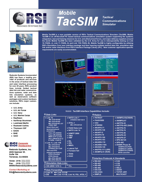
Redondo Systems Incorporated (RSI) has been a leading pro-products and services in the areas of tactical data link radar interface processing Mobile TacSIM Interface Capabilities Include:Data LinksMIL-STD-6016E MIL-STD-6016D MIL-STD-6016C ch1JTIDS TIDP Smart Host and terminal/network ♦NATO Link 1 STANAG 5501 Ed 4♦ATDL-1MIL-STD-6013A♦FAAD Data Link ♦NATO Link 14✧Radars♦PATRIOT ♦ FAAD/GBS ♦ CD2♦ ATSERIX ♦ AN/APG-71♦ AS/APS-138♦AN/MPQ-55(CWAR)♦ AN/MPQ-57♦ AN/TPS-32♦ AN/TPS-43E (DAR)♦ AN/TPS-70♦ AN/TPS-75TacticalCommunications SimulatorTacSIMMobileMobile TacSIM FeaturesMultiple tactical displays w Multiple hook readoutsw Operator input dialogs w System status ² Hardware Configuration w Ruggedized chassis w Off-the-shelf I/O cards ² Simulation Object Database w 2000 objects (minimum)² Network Support w Multiple workstations w Distributed processing w ² Scenario Processing w Automated creation w Nested scenarios w In-line documentation w In-line operator prompts w Selectable playback rate w Perform all manual actionswhile scenario executes w ² Data Recording w All message traffic w All operator actions w Errors recorded for analysis w Millisecond accuracy timetags ² Data Analysis w Real-time statistics w ODBC database source w Can process recorded data² Data Reduction w Real-time and post-test datareduction (DERG compliant)w Extensive filters w Prose, hex, octal and binary w Operator actions ² GPS Interfaces w GPS Sync, IRIG-B ² Motion Modeling w Default motion profiles w Real-time operator control ² Route Planning w w Terrain following using DTED ² Radar Simulation w Line-Of-Sight, Field-Of-View w Probability of Detection w Rotating/Non-Rotating radars w Jamming w Tracker module (optional)² Playback w Processes recording files w Recreates tactical displays w Recreates online DX ² Negative Testing w Hex/Binary/Octal messages w Transmit/Receive filtersMobile TacSIM uses ruggedized, durability. Mobile TacSIM functions much like an actual Tactical Data System (TDS) except that the Simulation Object Database from which messages are generated is initiated through manual operator actions, scenario events, and/or simulation data link input (e.g. DIS) rather than from sensor inputs. External interfaces configured into the TacSIM independently scan the Simulation Object Database and generate the appropriate primary and amplifying messages for each object. Message generation is based on object (e.g. TacSIM system, it can be configured to participate in a TacSIM network simply by connecting it to the TacSIM LAN. In this configuration, Mobile TacSIM can take advantage of the distributed processing and operator controls of a full TacSIM network, while maintaining fully integrated situation awareness and data availability at each workstation.CoreSimulation。
浩瀚电器重型电锅替换零部件手册说明书

VTMB22VB2S VB21VTMB2VB SERIES1 THRU45 - 678 - 9101112 - 13 - 14ELECTRICAL COMPONENTSVB SERIESELECTRICAL COMPONENTSILLUS.PART OF PART AMT.1417934-G1Block Assy. - Porcelain (208-240 V. Machine)(Incls.items 2, 3 & 4)..........................................AR 2SC-117-3Mach. Screw 10-24 x 11⁄4 Rd. Hd................................................................................................AR 3WS-23-20Washer.......................................................................................................................................AR 4NS-44-9Nut Assy 10-24 Hex “KEPS”......................................................................................................AR 5411497-B1Contactor (208-240 V. Machines)..............................................................................................AR 6417856-1Ground Lug (VB21, VB221) (1)7406708-G1Door - Breaker Panel (1)8412578-1Closure - Breaker (208-240 V.)(Shown) (1)9412578-2Closure - Breaker (480 V.) (1)10411501-14Circuit Breaker (50 Amp.)(208-240 V. Machines)......................................................................AR 11412577-1Box - Breaker. (1)12410472-9Block - Terminal (208/240 V.) (1)13410472-11Terminal Block (208-240 V.) (1)14410472-8Terminal Block (480 V.) (1)VB SERIESVB SERIES 5VB SERIESDOOR MECHANISM — OVENPL-40408-11011 THRU141516171821 - 2219 - 20VB SERIESDOOR MECHANISM - OVENILLUS.PART OF PART AMT.1410110-1Anchor - Spring (1)2417865-1Turnbuckle (36") (1)3405618-1Hook - Oven Door (1)4SC-90-1Bolt - Shoulder 1⁄2-13 x 2 Hex Hd (1)5408895-G1Crank Support Assy (1)6409240-2Spacer - 3⁄4 Pipe x 7⁄16 Lg (1)7404629-1Bearing - Hinge Pin (1)8408896-1Support - Crank (2)9410111-1Crank - Bell (1)10406363-1Spring - Door (Long) (1)11408895-G1Crank Support Assy (1)12409240-1Spacer - 3⁄4 x 5⁄16 Lg (1)13404629-1Bearing - Hinge Pin (1)14408896-1Support - Crank (1)15410090-G1Radius Bar Assy (1)16410089-1Arm - Door Control (1)17SC-90-1Bolt - Shoulder 1⁄2-13 x 2 Hex Hd (1)18PC-3-36Cotter Pin 3⁄32 x 1 Lg (1)19417860-1Bolt - Shoulder 3⁄8-16 x 3⁄4 Hex Hd (1)20417862-1Pin - Door Hinge (1)21410114-1Cover - Bottom Terminal (1)22410113-1Cover - Terminals (Top Oven Heat Elements) (1)412887-G1Door Frame Assy (1)VB SERIESBROILER GRID & DRIP SHIELDNAME OF PARTGrid Assy (1)Handle (1)Retainer - Drip Shield (1)Mach. Screw 10-24 x 1 Truss Hd (2)Spacer (2)Lock Nut 10-24 Light Flexloc (2)Post - Door (R.H.) (1)Post - Door (L.H.) (1)Drip Shield (1)Ball Bearing (Grid Carriage).........................................................................................................VB SERIESPL-40410-1915 - 16 CARRIAGE & LIFT UNIT (BROILER)PART OF PART406966-G1Carriage & Lift Mechanism (Incls.items 2 thru 7)......................................................................... 417866Spring - Carriage.. (1)405655-1Ball Bearing (Grid Carriage)......................................................................................................... 407488-1Pin - Bearing (2)417869-1Spacer (2)WS-3-3Washer (4)PC-3-36Cotter Pin 3⁄32 x 1 Lg (2)407619-1Ratchet Stop (1)406046-1Sleeve - Handle (1)414819-1Red Plastic Ball Handle................................................................................................................ 406056-2Adapter - Ball Handle. (1)407636-G1Push Rod Assy (1)417810-2Spring - Compression (1)NS-13-22Full Nut 3⁄8-16 Hex (2)406990-G1Grease Collector (1)407006-1Handle - Grease Collector (1)VB SERIESPL-40411-1ELECTRIC HEAT ELEMENTS(BROILER)PARTNAME OF PART407012-4Electric Heat Element 208 V........................................................................................................407012-5Electric Heat Element 240 V........................................................................................................407012-6Electric Heat Element 480 V........................................................................................................410465-1Retainer - Heating Element (3)407930-G1Heat Shield Assy (1)VB SERIES9 THRU141715 - 16PL-40412-1ELECTRIC HEAT ELEMENTS (OVEN)NAME OF PARTFrame Assy. - Top Elements (1)Frame Assy. - Bottom Elements................................................................................................... Element Assy. - Outer Top (208 V.)............................................................................................. Element Assy. - Outer Top (240 V.)............................................................................................. Element Assy. - Outer Top (480 V.)............................................................................................. Element - Outer Bottom (208 V.).. (1)Element - Outer Bottom (240 V.) (1)Element - Outer Bottom (480 V.) (1)VB SERIES2PL-40413-1MISCELLANEOUSNAME OF PARTFlue Riser (1)Strap - Back Attaching................................................................................................................Leg (SST) (4)Caster W/O Brake (2)Caster W/Brake (2)。
伯朗特操作说明书
5
自动 ........................................................................................................... 10
5.1 核对 ................................................................................................................................................... 10 5.1.1 按键说明 ...................................................................................................................................11 5.1.2 自动运行中修改程式 .................................................................................................................11 5.2 5.3 5.4 5.5 IO 状态 .............................................................................................................................................. 12 堆迭设定 ............................................................................................................................................ 12 取样不良 ............................................................................................................................................ 12 周期监视 ............................................................................................................................................ 13 5.5.1 输送带设定............................................................................................................................... 14 5.5.2 加工机设定............................................................................................................................... 14
BL-HB336G-TRB(VF细分)佰鸿一级代理推荐资料
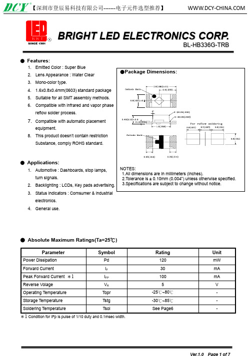
General use.● Absolute Maximum Ratings(Ta=25℃)Parameter Symbol Rating UnitPower Dissipation Pd 120 mWForward Current I F 30 mA Peak Forward Current *1I FP 100 mA Reverse Volage V R 5 V Operating Temperature Topr -25℃~80℃-Storage Temperature Tstg -30℃~85℃-Soldering Temperature Tsol See Page6 -*1 Condition for IFp is pulse of 1/10 duty and 0.1msec width.Ver.1.0 Page 1 of 7Intensity Bin Limits (At 5mA) BIN CODE Min. (mcd) Max. (mcd) K 12.3 18.5L 18.5 28.0M 28.0 42.0Tolerance for each Bin limit is ±15%Color Bin Limits (At 5mA)BIN CODE Min. (nm) Max. (nm)4 465 470Tolerance for each Bin limit is ±1nmV F Bin Limits (At 5mA)BIN CODE Min.(v) Max.(v)F 2 2.7 2.8G 1 2.8 2.9 G 2 2.9 3.0H 1 3.0 3.1 Tolerance for each Bin limit is ±0.05v● BIN :x x x V F B I N C O D EC o l o r B I N C OD EI n t e n s i t y B I N C O D EVer.1.0 Page 4 of 7●Judgment criteria of failure for the reliabilityMeasuring items Symbol Measuring conditions Judgement criteria for failureUx1.2=20mA Over Forward voltage V F ( V) I FUx2=5V Over Reverse current I R(uA) V R=20mA BelowSX0.5 Luminous intensity Iv ( mcd ) I FNote: 1.U means the upper limit of specified characteristics. S means initial value.2.Measurment shall be taken between 2 hours and after the test pieces have been returned tonormal ambient conditions after completion of each test.Ver.1.0 Page 5 of 7seconds per solder-land is to be observed. 2. Reflow Soldering Preheating : 140℃~160℃±5℃,within 2 minutes. 3. Preheating : 120℃~150℃,within 120~180 sec.Operation heating : 245℃±5℃ within 5 sec.260℃ (Max) Gradual Cooling (Avoid quenching). ● Handling :Care must be taken not to cause to the epoxy resin portion of BRIGHT LEDs while it is exposed to high temperature.Care must be taken not rub the epoxy resin portion of BRIGHT LEDs with hard or sharp article such as the sand blast and the metal hook .TimeVer.1.0 Page 6 of 7instantaneous voltage at the turning ON and OFF of the circuit. When using the pulse drive care must be taken to keep the average current within the rated figures.Also, the circuit should be designed so as be subjected to reverse voltage when turning off theBRIGHT LEDs. ● Storage:In order to avoid the absorption of moisture, it is recommended to solder BRIGHT LEDs as soon as possible after unpacking the sealed envelope.If the envelope is still packed, to store it in the environment as following: (1) Temperature : 5℃-30℃(41℉)Humidity : RH 60﹪Max.(2) After this bag is opened, devices that will be applied to infrared reflow, vapor-phase reflow, or equivalent soldering process must be: a. Completed within 24 hours.b. Stored at less than 30% RH.(3) Devices require baking before mounting, if: (2) a or (2) b is not met. (4) If baking is required, devices must be baked under below conditions: 12 hours at 60℃±3℃. ● Package and Label of Products: (1) Package: Products are packed in one bag of 3000 pcs (one taping reel) and a label is attached on each bag. (2) Label: BRIGHT LED LOGO Part No. Quantity BIN.Sealing Datexx xx xx LocationVer.1.0 Page 7 of 7。
百易控baykon称重控制仪表介绍
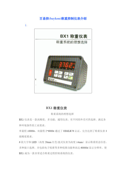
百易控(baykon)称重控制仪表介绍1.BX1称重仪表称重系统的理想选择BX1仪表是一款高精度,多功能,通用仪表,有不同的外壳可供选择,满足各种环境条件的工业需求。
单量程10000e,双量程2*6000e通过了OIMLR76认证,完全达到了称重仪表3级精度要求。
6段大字体LED(高度20mm红色/盘式仪表为高度14mm)显示称重状态信息。
多种接口选择,并包括电子校准等多种校准功能和高达60000d显示分辨率,使BX1成为一款非常适合称重过程控制系统的仪表。
特点●OIML认证10000e单量程2*6000e双量程●20mmLED显示●*10倍分辨率放大键●100万次键盘按压测试●标准RS232C接口●电池供电可选3种外壳形式●台式IP30,铝壳结构●台式/壁挂式IP65 全不锈钢外壳结构●盘装式IP65,不锈钢前面板,铝制壳体外部编程●利用BAYKON的”INDFACE”软件可实现外部编程和标定●打印标签的页眉和页脚通过PC修改电子标定●可非砝码标定,对于大型料罐,筒仓及其他称重系统有很大优势系统集成●RS232C接口●RS485/RS232C接口●以太网TCP/IP●Modbus RTU/TCP●Profibus●光隔离3路输入/3路输出模拟输出(0-10V/4-20mA)2.BX2仪表是一款高精度,多功能,通用仪表,有不同的外壳可供选择,满足各种环境条件的工业需求。
单量程10000e ,双量程2*6000e 通过了OIMLR76认证,完全达到了称重仪表3级精度要求。
2个ID 地址存储,标准和用户自定义的页眉/页脚,日期,时间,连贯的记录数和条形码是BX2仪表的重要特点。
多种接口选择,和可内置的各种通用称重模式,使得BX2成为一款非常适合称重系统和过程控制系统的仪表。
特点●2个用户独立命名的地址和内存●自动记录并存储数字皮重●标准和用户自定义的标签格式,日期,间和连续数●标准RS232C接口●电池供电可选应用模式●称重和打印●动态称重●自动灌装●峰值保持●分选3种外壳形式●台式IP30,铝壳结构●台式/壁挂式IP65 全不锈钢外壳结构●盘装式IP65,不锈钢前面板,铝制壳体电子标定●可非砝码标定●打印标签的格式可以通过串口由PC写入系统集成●第2个RS232C接口●第3个RS485/RS232C接口●以太网TCP/IP●Modbus RTU/TCP●Profibus●光隔离3路输入/3路输出模拟输出(0-10V/4-20mA3.BX3灌装控制器适合多种灌装控制BX3 仪表是一款专业的灌装控制器适用于多种液体,散装和颗粒的灌装及包装。
BMR200 无线网关 安装使用说明书

序言尊敬的客户,感谢您选择佰马公司产品。
安装配置与使用前请通读本说明书,您将从中了解正确的操作规范。
本说明书的操作说明对维持产品的良好工作状态十分重要。
本手册内容●无线网关产品简介●无线网关快速安装●无线网关参数配置佰马技术支持如有任何需要,敬请致电佰马服务专线************,我们将为您提供专业的技术支持与售后服务。
意见反馈如您在使用过程中发现产品资料的任何问题,可以通过以下方式反馈:E-mail:********************感谢您的支持,您的宝贵建议就是对我们最大的鼓舞。
版本说明由于产品升级等原因,佰马保留对本手册内容进行修改的权利。
各版本内容若有差异,请以佰马科技网站()最新公布的为准。
开箱检查每部佰马通信终端在出厂前,均经过严格之品检,并做强化之防撞包装处理,客户在拆箱后,请即刻进行下列检查步骤:1、检查产品型号铭牌是否与采购型号一致。
佰马产品铭牌说明,以BMR200为例:2、检查产品是否在运输过程中造成损伤。
3、检查主机与配件是否齐全。
设备的包装包括以下:一台网关主机一个电源两根4G天线一根串口线一根以太网线两个6PIN绿色接线端子一个2PIN绿色接线端子一个导轨片目录1产品简介 (6)1.1产品概述 (6)1.2产品结构尺寸图 (7)1.3物理特性 (7)2产品安装 (8)2.1接口与指示灯 (10)2.2连接安装 (10)3参数配置 (11)3.1网络设置 (12)3.1.1外网设置 (12)3.1.2内网设置 (15)3.1.3WIFI设置 (16)3.1.4在线探测 (17)3.2安全设置 (18)3.2.1DMZ主机 (18)3.2.2端口转发 (18)3.2.3网络过滤 (19)3.3系统设置 (21)3.3.1基础设置 (21)3.3.2密码管理 (21)3.3.3时间设置 (22)3.3.4日志设置 (23)3.3.5备份与恢复 (23)3.3.6路由器升级 (24)3.3.7远程配置 (25)3.3.8手动重启 (26)3.3.9定时重启 (26)3.4高级设置 (27)3.4.1动态DNS (27)3.4.2花生壳 (28)3.4.3静态路由 (28)3.4.4GPS定位 (29)3.4.5流量统计 (29)3.4.6串口通信 (30)3.4.7基站定位 (31)3.4.8DI/DO (31)3.5VPN设置 (32)3.5.1PPTP (32)3.5.2L2TP (34)3.5.3IPSec (35)3.5.4OpenVPN (37)3.6路由器状态 (38)3.6.1系统状态 (38)3.6.2网络状态 (39)3.6.3VPN状态 (39)3.6.4系统日志 (39)3.7数据采集配置 (40)3.7.1接口设置--串口设置 (40)3.7.2接口设置--TCP服务端配置 (41)3.7.3采集规则--Modbus规则 (42)3.7.4采集规则--MC采集规则 (44)3.7.5服务端配置 (44)3.7.6服务端封装类型-JSON (45)3.7.7服务端封装类型-HJ212 (47)3.7.8服务端协议-TCP、UDP (48)3.7.9服务端协议-MQTT (49)3.7.10服务端协议-HTTP (50)3.7.11服务端协议-MODBUS TCP (51)1产品简介1.1产品概述BMG500是一款工业物联网智能网关,集数据智能采集、多种协议转换、智能网关、全网通/4G无线通信、数据处理转发、虚拟专网、本地存储等功能于一体。
新佰特 4 通道数字存储示波器 (DSO) 用户手册说明书
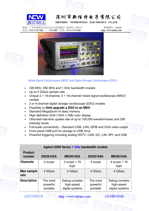
SHENZHEN NEWBESTOOLS ELECTRONICS CO.,LTD地址:广东省深圳市宝安区31区前进路水口花园西三巷8号邮政编码:518133 电话:/27851665传真:Mixed Signal Oscilloscopes (MSO) and Digital Storage Oscilloscopes (DSO).•300 MHz, 500 MHz and 1 GHz bandwidth models•Up to 4 GSa/s sample rate•Unique 2 + 16-channel, 4 + 16-channel mixed signal oscilloscope (MSO) models• 2 or 4-channel digital storage oscilloscope (DSO) models•Flexibility to field upgrade a DSO to an MSO•Standard MegaZoom III deep memory•High-definition XGA (1024 x 768) color display•Ultra-fast real-time update rate of up to 100,000 waveforms/sec and 256 intensity levels•Full-scale connectivity – Standard USB, LAN, GPIB and XGA video output •Front panel USB port for storage to USB drive•Powerful triggering including analog HDTV, CAN, I2C, LIN, SPI, and USBAgilent 6000 Series 1 GHz bandwidth modelsProductnumber DSO6102A MSO6102A DSO6104A MSO6104A Channels 2 scope 2 scope + 16logic4 scope 4 scope + 16logicMax samplerate4 GSa/s 4 GSa/s 4 GSa/s 4 GSa/sDescription The mostpowerfulportableDebug complexhigh-speeddigital systemsThe mostpowerfulportableDebug complexhigh-speeddigital systemsSHENZHENNEWBESTOOLS ELECTRONICS CO.,LTD地址:广东省深圳市宝安区31区前进路水口花园西三巷8号 邮政编码:518133 电话:************* / 27851665 传真:************* scopes with MegaZoom III with 2 scope + 16 logic channels scopes with MegaZoom III with 4 scope + 16logic channelsAgilent N2915A MSO upgrade, for DSO605(*)A ---Includes a logic cable kit, a label and an upgrade license to activate the MSO features in a DSO 500MHz or 1 GHz oscilloscope.Agilent 6000 Series 500 MHz bandwidth modelsProductnumber DSO6052A MSO6052A DSO6054A MSO6054A Channels2 scope 2 scope + 16logic 4 scope 4 scope + 16logic Max sample rate 4 GSa/s4 GSa/s4 GSa/s4 GSa/sDescriptionPortable scopes with MegaZoom III Debug digital systems with 2 scope + 16 logic channels Portable scopes with MegaZoom III Debug digital systems with 4 scope + 16 logicchannelsAgilent N2915A MSO upgrade, for DSO605(*)A ---Includes a logic cable kit, a label andan upgrade license to activate the MSO features in a DSO 500MHz or 1 GHz oscilloscope.Agilent 6000 Series 300 MHz bandwidth modelsProduct number DSO6032A MSO6032A DSO6034A MSO6034A Channels 2 scope 2 scope + 16logic 4 scope 4 scope + 16logic Maxsample rate2 GSa/s2 GSa/s2 GSa/s2 GSa/sDescription Lowest-costportable scopes with MegaZoom III Debug complex high-speed digital systems with 2 scope + 16 logic channels Portable scopes with MegaZoom III for high-performance problem solving Debug complex high-speed digital systemswith 4 scope + 16 logic channels深圳市新佰特电子有限公司SHENZHENNEWBESTOOLS ELECTRONICS CO.,LTD 地址:广东省深圳市宝安区31区前进路水口花园西三巷8号 邮政编码:518133 电话:************* / 27851665 传真:************* Agilent N2914A MSO upgrade, for DSO603(*)A ---Includes a logic cable kit, a label and an upgrade license to activate the MSO features in a DSO 300MHz oscilloscope。
陶氏反渗透和纳滤膜技术手册2016版全解

2-4.13陶氏苦咸水系列产品概述............................................................................................... 24
极低能耗反渗透元件
XLE-440极低能耗反渗透元件........................................................................................ 69
2-9陶氏FILMTEC™抗污染型反渗透元件
BW30-365-FR抗污染型反渗透元件............................................................................... 71
2-10陶氏FILMTEC™海水淡化反渗透元件
小型海水淡化反渗透元件
SW30-2514 SW30-2521 SW30-2540 SW30-4021 SW30-4040 ............Βιβλιοθήκη ...............77
TM陶氏化学公司或其附属公司的商标
目录-3
高脱盐率低能耗四英寸海水淡化反渗透元件
BW30-400-FR抗污染型反渗透元件............................................................................... 73
BW30-400/34i-FR端面自锁高产水量抗污染型苦咸水反渗透膜元件............................. 75
电力载波芯片BL3361
LOW POWER NARROW BAND FM IF BL3361DESCRIPTIONThe BL3361 is designed for use in FM dual conversion communication. It contains a complete narrow band FM demodulation system operable to less than 2.0V supply voltage. This low power narrow band FM IF system provides the second converter, second IF, demodulator. Filter Amp and squelch circuitry for communications and scanning receivers.FEATUREOperating voltage range : 2.0V ~ 8.0VLow Current consumption I C C=3.9mA Typ. (V C C=4.0V)Excellent input sensitivity(-3dB Limiting = 2.6 µVrms Typ.)Low number of external parts requiredOperating frequency up to 60MHzEncapsulation:SOP-16PIN CONFIGURATIONABSOLUTE MAXIMUM RATINGS (Ta=25°C)Characteristic Symbol Value Unit Maximum Supply Voltage Vcc(M AX)10 V Supply Voltage Range Vcc 2.0~8.0 V Detector Input Voltage V I N(DE T) 1.0 Vp-p RF Input Voltage V I N(R F) 1.0 Vrms Mute Function V M UT E-0.5~+5.0 Vpeak Junction Temperature T J150 °C Power Dissipation PD 1.5 W Operating Temperature Topr -30~+70 °C Storage Temperature Tstg -65~150 °CELECTRICAL CHARACTERISTICS(Unless otherwise specified: Ta=25°C, Vcc=4V, fo=10.7MHz, fm=1kHz, ∆f=±3kHz)Characteristics Symbol Test conditions Min Typ Max UnitI C C1Squelch off (V12=2V) 2.9 3.9 4.9mA Squelch CurrentI C C2Squelch on (V12=0V) 4.4 5.4 6.4Audio Output Voltage V OU T Vin=10mVrms 130 160 200 mV r ms Input Limiting Voltage V I N(Li m)-3dB Limiting 2.6 6.0 µVTotal HarmonicTHD V OU T =170mVrms 0.86 % DistortionDetector OutputV NO No Input Signal 1.2 1.5 1.8 V VoltageDrop Voltage AF Gain-3 -0.6 dB Loss ∆Gv Vcc=4V → 2VDetector OutputR OU T450 ΩResistanceFilter Gain Gv Vin=5mVrms, f=10kHz 40 50 dBFilter Output DCV O(D C) 1.0 1.3 1.6 V DC VoltageMute Low Resistance R ON(M u t e)Mute Switch-on 30 50 ΩMute High Resistance R O ff(M u t e)Mute Switch-off 1.0 11 mΩScan Control Low V L(S c a n)Mute off(V12=2V) 0 0.4 V DC Scan Control High V H(S c a n)Mute on(V12=0V) 3.0 3.5 V DC Trigger Hysteresis V TH Squelch on/off 45 100 mV r ms Mixer Conversion Gain G V(M i x)28 dB Mixer Input Resistance R i(M i x) 3.3 kΩMixer Input Capacitance C i(M i x) 2.2 pFBLOCK DIAGRAM AND TEST CIRCUITAPPLICATION CIRCUITTYPICAL PERFORMANCE CHARACTERISTICSOUTLINE DRAWING。
- 1、下载文档前请自行甄别文档内容的完整性,平台不提供额外的编辑、内容补充、找答案等附加服务。
- 2、"仅部分预览"的文档,不可在线预览部分如存在完整性等问题,可反馈申请退款(可完整预览的文档不适用该条件!)。
- 3、如文档侵犯您的权益,请联系客服反馈,我们会尽快为您处理(人工客服工作时间:9:00-18:30)。
● DEVICE NUMBER:BL-HZ336G-L8-TRB
(2mA)
● Absolute Maximum Ratings(Ta=25℃)
Parameter Symbol Rating Unit
Power Dissipation Pd 6 mW
Forward Current I F 2 mA Peak Forward Current *1I FP 100 mA Reverse Volage V R 5 V Operating Temperature Topr -40℃~85℃-
Storage Temperature Tstg -40℃~85℃-
Soldering Temperature Tsol See Page 8 -
*1 Condition for IFp is pulse of 1/10 duty and 0.1msec width.
● Typical Electro-Optical Characteristics Curves R e l a t i v e l u m i n o u s i n t e n s i t y (@20m A )
Forward current (mA)F o r w a r d c u r r e n t (m A )
Fig.1 Relative intensity vs. wavelength
R e l a t i v e r a d i a n t i n t e n s i t y
vs. ambient temperature Fig.2 Forward current derating curve
NOTE: 4000 pcs PER REEL
●Package Method:(unit:mm) Vacuum
12 bag/box
Tolerance for each Bin limit is ± 15%.
V F Bin Limits (At 2mA)
BIN CODE Min.(v) Max.(v)
D1 2.2 2.3
D2 2.3 2.4
E1 2.4 2.5
E2 2.5 2.6
F1 2.6 2.7
F2 2.7 2.8
G1 2.8 2.9
G2 2.9 3.0 Tolerance for each Bin limit is ± 0.05V
●BIN:x x x
C o l o r B I N C O
D E
I n t e n s i t y B I N C O D E
y
●Judgment criteria of failure for the reliability
Measuring items Symbol Measuring conditions Judgement criteria for failure
Level*1.1 Forward voltage V F ( V) I F
=2mA Initial
U*2 Reverse current I R(uA) V R
=5V Over
Level*0.7 Luminous intensity Iv ( mcd ) I F
=2mA Initial
Note: 1.U means the upper limit of specified characteristics.
2.Measurment shall be taken between 2 hours and after the test pieces have been returned to
normal ambient conditions after completion of each test.
seconds per solder-land is to be observed.
2. Reflow Soldering
Preheating : 140℃~160℃±5℃,within 2 minutes.
3.
Preheating : 120℃~150℃,within 120~180 sec.
Operation heating : 245℃±5℃within 5 sec.260℃ (Max)
Gradual Cooling (Avoid quenching).
Time
●Handling :
Care must be taken not to cause to the epoxy resin portion of BRIGHT LEDs while it is exposed to high temperature.
Care must be taken not rub the epoxy resin portion of BRIGHT LEDs with hard or sharp article such as the sand blast and the metal hook.
instantaneous voltage at the turning ON and OFF of the circuit. When using the pulse drive care must be taken to keep the average current within the rated figures.
Also, the circuit should be designed so as be subjected to reverse voltage when turning off the BRIGHT LEDs. ● Storage:
In order to avoid the absorption of moisture, it is recommended to solder BRIGHT LEDs as soon as possible after unpacking the sealed envelope.
If the envelope is still packed, to store it in the environment as following: (1) Temperature : 5℃-30℃(41℉)Humidity : RH 60﹪Max.
(2) After this bag is opened, devices that will be applied to infrared reflow, vapor-phase reflow, or equivalent soldering process must be: a. Completed within 168 hours.
b. Stored at less than 30% RH. (3) Devices require baking before mounting, if: (2) a or (2) b is not met. (4) If baking is required, devices must be baked under below conditions:
48 hours at 60℃±3℃. ● Package and Label of Products: (1) Package: Products are packed in one bag of 4000 pcs (one taping reel) and a label is attached
on each bag. (2) Label: BRIGHT LED LOGO
Part No. Quantity
BIN.
Sealing Date xx xx xx
Location。
