KMX磨床充退磁控制器英文说明书
TLXK-150磁力分选设备中英文说明书

潍坊特力械设备有限公司Weifang Teli Mechanical Equipments Co., Ltd.TLXK-150干选生产线说明书Manual of TLXK-150 dry separation production line潍坊特力械设备有限公司Weifang Teli Mechanical Equipments Co., Ltd.一.生产流程步骤:Production process steps:1.总装示意图1.Final assembly diagram总装示意图 Final assembly diagram2.生产步骤: Production steps (一)由装载机将原矿装入到料仓(示意图中1)。
i. Load raw ores into stock bin by the loader(step 1 in schematic diagram). (二)料仓不间断下料到上料杆(示意图中2)。
ii. Stock bin continuously unload raw ores to loading rod (step 2 in schematic diagram). (三)上料杆将原矿输送到振动给料机(示意图中3)。
iii. Loading rod conveys raw ores to vibrator feeder (step 3 in schematic diagram). (四)振动给料机将原料均匀输送到磁选机组(示意图中4)。
iv. Vibrator feeder conveys raw materials to magnetic separator (step 4 in schematic diagram).(五)磁选机组将原矿分选后分别进入到精矿输送杆、中矿输送杆、尾矿输送杆((示意图中5、6、7))。
v. Raw ores are conveyed into concentrate conveying rod, middlings conveying rod and tailings conveying rod after Separated by magnetic separator(steps 5,6,7 in schematic diagram).7.Tailings conveying rod6.Middlings conveying rod2.Loading rod5.Concentrate conveying rod4.Magnetic separator3.Vibrating feeder1.Loading binWeifang Teli Mechanical Equipments Co., Ltd.料仓stock bin图 1二.各部件说明:II. Description of various parts:1.料仓:Stock bin:装载机上料。
数控齿条磨简明使用手册828DV15教材
重庆磨床有限责任公司数控齿条磨床简明使用手册MCK7170V1.5机床标准配置SIEMENS828D修整滚轮、动静压主轴、3D测头PLC版本CQM94 828D V2H人机界面版本CQM94 V2X2016/10/17 V1.52016/07/25 V1.32016/02/29 V1.12016/02/01 V1意见及建议反馈:cqmlf@ 编制者:刘峰一、概述重庆磨床有限责任公司自2001年成规模生产、改造的数控外圆磨床。
产品型号包括MK1320/MK1332(数控外圆磨床)、MKS1320/MKS1332(数控高速外圆磨床)、MKS1620/MKS1632(数控端面外圆磨床)、MK8240/MKS8240(数控曲轴磨床)。
如未加说明有,本手册中“机床”泛指“上述所有型号数控机床”。
机床主要配置西门子802D及802DSL T/M value 、802DSL G/N plus、828D或FANUC 0iTC及FANUC 0iTD数控系统。
本手册所述数控系统为828D。
二、操作注意事项因意外事故可能会造成人身伤害和机床损坏,机床配置了安全装置(包括硬件和软件):1, 机床防护罩(包括砂轮防护罩)2, X、Z 轴的极限限位开关。
在此开关范围内的软极限开关(参数设定)和可编程软极限。
3, 急停按钮。
4, 进给暂停按钮、复位键。
5, 过热、过流保护开关,以及互锁开关、门开关(选配)。
6, 报警显示,信息显示,原点回零异常警示(增量式编码器)。
7,使用程序锁或者操作权限(密码)来保护程序和变量以及参数不被意外修改。
8,基本联锁:这种联锁必须修改PLC才能改变,例如砂轮未启动时冷却液不能启动9,可变联锁:这种联锁可以通过修改参数取消,例如将动静压主轴更换为普通主轴时,可以取消主轴油泵和砂轮的联锁。
主轴压力继电器故障时,可以取消压力继电器和砂轮的联锁。
10,界面已经编入多种保护措施,如果需要修改请联系我公司技术人员。
磨床plc控制系统设计
(3)从功能上看,50%以上的平面磨床不仅仅用于水平平面的加工,而且转向台阶、成形、切入、快速抖动、三维空间曲线等表面磨削加工,在国际上如BLM、ELB公司以平面磨床为基础变化而成的五轴联动磨削中心,可以实现复杂曲面的磨削;Trutech、Unison公司研发的柔性磨削系统,可以实现成形、外圆、无心、工具、轮廓等磨削工艺;还有Parker、裕福公司等的快速抖动平面磨床等,都反映出平面磨床是磨床类机床中最具演变潜力的一种机型。
Key words: surface grinding machine,PLC,control system
第1章 绪论
1.1 课题的背景及其意义
在十八世纪初,为了适应自行车、钟表、枪械和缝纫机等零件淬硬后的加工,美国、英国和德国分别研制出了使用天然磨料作为砂轮的磨床。这些磨床是在当时已有的机床如刨床、车床等上面加装磨头改制而成的,这些磨床结构简单,刚度较低,磨削时容易产生振动,操作时要求工人要有很高的技艺才能磨出较为精密的工件。
PLC is the computer technology and traditional relay contact control technology combined with the product, it has overcome the relay contact control system in mechanical contact of the complex wiring, low reliability, high power consumption, universality and flexibility of the shortcomings of the poor, make full use of the advantages of a e of PLC control grinding machine running, so the circuit is simplified, improved reliability, response speed to be accelerated apparently, the accuracy is more accurate; the grinder start, stop, failure to stop, emergency stop function, be under the operational requirements of the control switch grinder flexible; with light load, overload, open phase and voltage unbalance protection; field display running state, intelligent monitoringand save a lot of relay components. The machine has higher working efficiency. Based on the M7120plane grinding machine as an example, introduces the grinding machine control system 's PLC transformation.
mastrys MC索克曼UPS电源说明书 中文手册改板
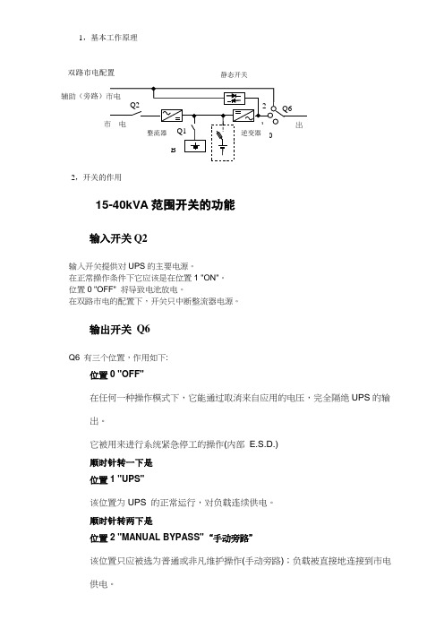
1,基本工作原理双路市电配置静态开关2,开关的作用15-40kVA范围开关的功能输入开关Q2输入开关提供对UPS的主要电源。
在正常操作条件下它应该是在位置1 "ON"。
位置0 "OFF" 将导致电池放电。
在双路市电的配置下,开关只中断整流器电源。
输出开关Q6Q6 有三个位置,作用如下:位置0 "OFF"在任何一种操作模式下,它能通过取消来自应用的电压,完全隔绝UPS的输出。
它被用来进行系统紧急停工的操作(内部 E.S.D.)顺时针转一下是位置1 "UPS"该位置为UPS 的正常运行,对负载连续供电。
顺时针转两下是位置2 "MANUAL BYPASS"“手动旁路”该位置只应被选为普通或非凡维护操作(手动旁路);负载被直接地连接到市电供电。
它可被用于UPS 从辅助市电给应用供电有故障的情形下,在等候技术人员的干预时使用。
电池开关Q13,面板介绍高级模拟面板D2: 表意文字显示区D3: 文本和图形显示区域 BL: 亮光状态条 P1: EXIT 退出 P2: UP 上翻 P3: DOWN 下翻P4: ENTER 回车/OK 确定图标含义BLMASTERYS 3/3 30KVALOAD PROTECTED BATTERY OK P1P2P3P4D3D2亮光条含义光亮条对负载供电的情况提供一个直接的指示显示:红=当前无电源或临近停工。
黄=电源存在但不稳定或临时。
绿=电源安全且稳定。
模拟面板菜单下段描述了模拟面板上可用的菜单以及它们的作用。
如图所示,显示被组织入菜单和子菜单。
访问菜单按ENTER回车键,返回到更高一级菜单,按ESC 。
使用UP 上翻/ DOWN下翻键滚动每级可用的资料信息。
当UPS 被并联连接时,模拟面板显示的系统信息好象这里只有唯一一台UPS 。
选择UPS 数量,显示关于各台机器的信息。
查看报警在正常模式下查看系统报警:从面板操作,按ESC退到原始界面如下:然后按回车键进入SYSTEM按回车进入>ALARM按回车进入>ACTIVE ALARM按回车进入报警详情如:A00:general ALARM。
西安鸣士机电 KMX-50 3S电磁吸盘用充退磁控制器 说明书

KMX-50/3S电磁吸盘用充退磁控制器(智能型)使用说明书西安鸣士机电开发有限公司一、概述平面磨床的充退磁问题一直困扰着磨床生产和使用厂家,以前采用变压整流后通过开关手控进行充退磁,不仅操作繁琐,费力费时,而且充退磁效果很不理想。
加工合金材料及热处理过的材料残磁很大,影响工件的加工精度和工作效率,使磨床的加工范围受到限制,不能满足现代机械制造业的要求。
针对这些问题,我公司精心设计生产了KMX 系列充退磁控制器,有效地解决了平面磨床的充退磁问题,其基本特性和功能如下:采用单片机控制,实现无触点输出,增加了可靠性;充磁输出电流连续可调,可满足不同磨床吸盘加工不同工件对磁力的要求;按退磁曲线自动完成退磁过程,能使每块吸盘达到最佳的退磁效果;退磁时间长短可调,使磨床加工不同的材料均能取得最佳的退磁效果;具有过压、过流、短路、过热等保护功能;具有欠电流保护功能,可通过主机和磁盘联锁实现欠磁保护,以保证设备和人员的安全;故障代码显示,方便排除故障。
体积小,安装调试方便。
二、型号及技术参数 型号额定输入 电压(V) 输出电压 (V)最大输出 电流(A)退磁时间 (S) KMX-50/3S 三相380V AC DC0~110V 50A12~36S 注:1. 本公司可为用户设计、生产特殊要求的产品;2. 选择KMX 系列的最大输出电流一定要大于吸盘的最大额定电流值。
使用条件:环境温度:-10℃~+40℃; 相对湿度:≤90%(20℃);环境:使用地点应无易爆导电尘埃及腐蚀性气体;输入电压波动范围:±10%以内;安装方式:垂直安装,并保持证控制器上方风机处通风良好。
干磨工件时,注意不要使铁末、粉尘进入电器箱内,以免引起电器短路。
安装、调试:对电磁吸盘的要求: 电气参数与控制器相匹配,吸盘的额定电流= ; 线圈内部无匝间短路及开路现象;用500V 兆欧表测量,磁盘对地绝缘电阻应不低于1M Ω。
建议:新机床的设计采用及老机床的改造应加相应功率的隔离变压器。
ZGM65磨煤机中英文对照说明书

ZGM65中速辊式磨煤机使用和维护说明O P E R A T I O N A N D M A I N T E N A N C E I N S T R U C T I O N S O F Z G M65 R O L L E R M I L LZGM65型中速辊式磨煤机使用和维护说明书OPERATION AND MAINTENANCEINSTRUCTIONSOF ZGM65 ROLLER MILL北京电力设备总厂BEIJING POWER EQUIPMENT GROUP2011年11月November 2011目录CONTENTS前言 (1)Foreword (1)C h a p t e r1 O P E R A T I O N I N S T R U C T I O N S F O R Z G M65 R O L L E R M I L L (2)1. 代号和技术数据 (3)1. Symbol And Technical Data (3)2. 工作原理 (4)2. Grinding principle of the ZGM mill (5)3. 部件介绍 (6)4. 使用、操作要求 (15)4. Request of operation (16)5. 启、停说明 (22)5. Start-up and putting out operation (22)6. 启动前和运行检查 (28)6. Inspection prior to start and preservice inspection (28)7. 运行故障及处理 (31)7. Faults and remedy (33)C h a p t e r2M A I N T E N A N C E A N D R E P A I R I N S T R U C T I O N S (36)1. 维护、检修注意事项 (37)1. Maintenance, inspection and repair (37)2. 停机时的保养与维护内容 (38)2. Maintenance and repair measures at coal mill standstills (38)3. 维护、检修要求 (45)3. Requirement of maintenance and repair (48)4. 碾磨件及内部零部件拆卸与安装 (52)4. Dismantling and mounting of the mill internal elements and the grinding parts (52)5. 内部部件的维修 (54)5. Repair of mill internal components (54)C h a p t e r3 O P E R A T I O N & M A I N T E N A N C E I N S T R U C T I O N S F O R T U R N I N G G E A R (64)1. 技术要求 (65)2.使用要求 (66)2. Employ Instructions (66)3. 安装与调整 (67)3. Assembly and adjust (67)4. 维护保养 (67)4. Maintenance (67)C h a p t e r4 M O U N T I N G & T R I A L R U N I N S T R U C T I O N S (69)1. 安装事宜 (70)2. 安装说明 (71)2. Mounting Instructions (71)3. 启动前的调试 (84)3. Trial run (84)附录: (86)附表1ZGM65型中速辊式磨煤机大件起吊单重重量表 (86)Appendix: (86)Appendix 1 Weight of main parts of ZGM65 mill (86)附表2ZGM65型中速辊式磨煤机润滑油脂一览表 (88)Appendix2: ..... .. (89)前言Foreword感谢您选用了我厂的ZGM型中速辊式磨煤机,为了使您更好地了解设备,使设备更好地为您的系统服务,我们编写了这本使用说明书,希望能给您以帮助,并真诚地希望您对其中的不足之处给予指出。
CADMAN TOUCH使用手册(2011)
目
录
说明 ....................................................................................................................................................2 简 介: .........................................................................................................................................4
一、常用信息: ........................................................................................................................5 系统: ........................................................................................................................................5 按钮: ........................................................................................................................................5 触摸屏 ........................................................................................................................................6 用户级别: ................................................................................................................................7 对触摸屏的数据进行备份:.....................................................................................................7 二. 启动和停止机床 .........................................................................................................................8 启动: ........................................................................................................................................8 关机: ........................................................................................................................................8 三.手动模式 ....................................................................................................................................9 主菜单: ....................................................................................................................................9 主菜单中的参数: ..................................................................................................................10 屏幕上工序列表中各参数含义:...........................................................................................14 四、编辑模式 ..................................................................................................................................28 主菜单 ......................................................................................................................................28 在主菜单中的其它参数:.......................................................................................................33 增加,删除程序: ........................................................................................................................34 新建程序: .................................................................................................................................34 五.自动生产模式: .........................................................................................................................35 主菜单: .....................................................................................................................................35 编辑页面: ..............................................................................................................................35 轴的页面: ..............................................................................................................................36 模拟仿真页面: ......................................................................................................................37
数控机床英语词汇

数控机床英语词汇数控机床机械零件mechanical parts游标卡尺slide caliper千分尺micrometer calipers攻丝tap塑性变形plastic distortion脆性材料brittleness material刚度准则rigidity criterion垫圈washer垫片spacer技术要求technical requirements装配图assembly drawing尺寸标注size marking零件图part drawing标准件standard component剖视图profile chart视图view投影projection机械制图Mechanical drawing电火花加工electric spark machining 电火花线切割加工electrical discharge wire - cutting 步进电机stepper motor镗床boring machine钻床drill machine铣床milling machine伺服电机actuating motor工业造型设计industrial moulding design电动机electromotor集成电路integrate circuit液压hydraulic pressure加工machining铸造found装配assembling拉孔broaching拉床broaching machine焊weld压模stamping锻forge磨床grinder车削turning钻削镗削bore车床lathe车刀lathe tool加工中心machining center齿轮gear齿轮加工gear machining工件work-piece铣刀milling cutter铣削mill螺钉screw螺纹加工thread processing半导体元件semiconductor element正火normalizing退火anneal热处理heat treatment硬度rigidity应力stress变形deformation变形力deforming force精度precision机械加工余量machining allowance金属切削metal cutting机床machine toolWater jet looms喷水织机Weaving Preparatory Machinery, Weaving Machinery, TuftingMachinery织造准备机、织造机、簇绒机Weaving Preparatory and Auxiliary Machinery织造准备及辅助机Weaving Auxiliary Machinery and Additional Devices 织造辅助机械及附加装置Washing, Bleaching, Dyeing, Printing, Finishing and Make-up Machinery洗涤、漂白、染色、印花、整理及包装机械Washing, Bleaching and Wet Treatment 洗涤、漂白及湿式处理机Warping machines整经机Warp stop motions断经自停装置Top printing machines套色印花机Thermo-fixing machines 热定形机Tentering and stentering machines拉幅机Tensionless dryers无张力干燥机Spinning Machinery纺纱机Spinning Machinery and TwistingMachines for Natural and Man Made Fibres, Wadding, Felting and Hat-Making Machines, Non Woven Fabric Machinery, Cordage and Rope-Making Machinery天然纤维和化学纤维用纺纱机及加捻机械,填絮,缩绒,制帽机,无纺织物机械,搓绳制绳机。
MD850AY说明书(中英文)

S EEKERThe dynamic Separator for coal mill 煤磨动态选粉机OPERATION AND INSTRUCTION安装使用说明书MianYang Seeker Science & Technology Development Co.Ltd.Mianyang•Sichuan•China绵阳西金科技发展有限公司目录Contents1.用途Application2.主要技术参数Main Technical Data3.结构及工作原理Structure and Working Principle4.安装与试运转Installation and Test run5.操作、维护及检修Operation, maintenance and overhaul6.备件清单Spare part listing7. 图纸清单drawing listing附录(一)润滑脂管路安装示意图.The appendix (一) which is the pipeline installation sketch map of lubricant system.Notice proceeding1.用途Application本煤磨动态选粉机主要适用于煤粉制造过程中的煤粉的分级。
The SEEKER MD coal-mill dynamic separator is the classification equipment for coal powder of coal grinding. 2.主要技术参数Main Technical Data转速Rotation Rate 150~300 r/min空气量Treatment air rate 48000~51000 m3/h转子直径Rotor diameter φ1450 mm煤粉产量Coal powder output 22~28 t/h(R80μm2-5%)电机Motor 型号type YTSP200L-4功率power 30KW额定转速specified speed 1480 r/min减速机reducer 型号type B2SV02B速比ratio 5稀油站Oil station XYZ-10G结构及工作原理Structure and Working Principle3.1结构Structure本高效选粉机主要有传动装置、回转部分、壳体部分、收尘部分、润滑系统组成。
KSZ-5A2充退磁器控制器说明书

显示
1. 初始上电显示
和
交替显示,
代表的是当前设定输出电压
110V,
代表的是当前设定欠磁连锁电流 3A。
2. 充磁工作中,例如显示 小数点指示充磁状态。
3. 退磁工作中,数码管显示
,那么退磁器的实际工作电流 4.8A,
最后一位
,直到
闪烁,表示退磁完成。
安装接线
端子位号 1和2 3和4 5 6 7 8 9 10 11 12
设定其他参数步骤相同
故障内容及诊断
故障代码
故障类型
电流过大
检查磁盘线圈是否漏电,磁盘是否短路,输出电流是否 过大,如不是上述问题请返厂维修
磁盘漏电
检查磁盘线圈是否漏电,磁盘是否短路,如不是上述问 题请返厂维修
温度过高
检查散热风道是否堵塞,风扇是否在旋转,如不是上述 问题请返厂维修
检查充磁和退磁信号是否同时输入了,如不是上述问题 充磁、退磁信 请返厂维修 号同时输入
功能码
F01 F02 F03 F04 F05 F06
名称
输出电压 保留
欠磁输出连锁 过电流保护值
振荡周期 退磁时间
设定范围
0-200V --
1-8A 4-8A 0.1-5 秒 1-15 秒
KSZ-5A2 出厂 设定
110v -2A 8A
1秒 6.3 秒
备注
用户常用 * --
用户常用 * 特殊用途
用户常用 * 用户常用 *
目录
型号及技术参数..............................................................................1 使用条件及使用注意事项..............................................................2 显示..................................................................................................3 安装接线..........................................................................................4 参数一览表......................................................................................5 操作流程..........................................................................................6 故障内容及诊断..............................................................................7 售后服务条款..................................................................................8
MachMotion 1000系列铣床控制器操作手册说明书

1000 Series Mill Control OPERATING MANUALSpecializing in CNC Automation and Motion Control2 | P a g eG0131This manual covers the operation of the 1000 Series Mill Control.Formatting Overview:•Menus, options, icons, fields, and text boxes on the screen will be bold (e.g. the Help icon).•Clickable buttons will be bold and within brackets (e.g. the [OK] button).•Directory names, commands, and examples of editing program files will appear in Courier New fontThis manual as well as all other MachMotion manuals can be found at Copyright © 2014, MachMotionAll rights reserved.P a g e | 3 1000 Series Mill ControlG0131Table of Contents1INTRODUCTION (5)1.1Control Startup (5)1.2Overview (5)2HOMING (6)3PROGRAMMED MOVEMENT (7)3.1MDI (7)3.2G-Code (7)3.2.1G-Code File Controls (8)3.2.2Running a G-Code File Example (8)3.2.3Running a G-Code File with the Single Block Option (9)3.2.4Block Delete Option (9)3.2.5Running a G-Code File with the Run From Here Option (9)3.2.6Tool Path Screen (10)3.3Advanced (10)3.3.1Dry Run (10)3.3.2M-S-T Lock (10)3.3.3Regen Tool Path (11)3.3.4Show Boundaries (11)3.3.5Jog Follow (11)4TOOLS, TOOL OFFSETS, AND CUTTER COMPENSATION (11)4.1Tools and Tool Offsets (11)4.1.1Fixed Tool Set Height (11)4.1.2Random Tool Set Height (11)4.1.3Auto Tool Setter (12)5SPINDLE CONTROL (13)5.1G-Code Spindle Control (13)5.2Manual Spindle Control (13)5.2.1Spindle (13)5.2.2Mist (14)5.2.3Coolant (14)6FIXTURE OFFSETS (14)7APPENDIX A – STARTUP PROCEDURE (15)8APPENDIX B (16)4 | P a g e8.1Warranty Information (16)8.2Additional Resources (16)P a g e | 5 1INTRODUCTION1.1Control Star tupTo open the control software double-click on the Mill profile icon on the desktop or open the Mach4 Loader and choose a profile from the list.FIGURE 1 – CONTROL ICONS1.2OverviewThis manual gives the process for basic operation of a mill using the MachMotion control screen. Depending on the control type, the control screen will display slightly different. The two screens are shown below, followedby a brief summary of the different sections of the screen.FIGURE 2A – STANDARD CONTROL SCREEN OVERVIEW6 | P a g eFIGURE 2B – WIDESCREEN CONTROL SCREEN OVERVIEWFor a quick reference, the description of each zone is located below.1.The tool path window shows the path the tool will take when a G-Code file is loaded. G-Code linenumber display (can also show percentage complete with setting change) and part counter display.2.Unlock the screen to access certain features/settings. Use DRO mode to measure or run in manualmode. DRO mode is has no effect on fixture offsets.3.The axis DROs show the current location and homing state (Green DROs indicate part coordinates,brown DROs indicate machine coordinates. The axis label LEDs turn green when the axis is homed).4.The axes DROs display the remaining travel distance to complete the current line of G-Code. Changebetween part and machine coordinates by clicking [Machine Coordinates].5.Feed rate control and status6.Spindle control and status, Mist & Coolant, and Auxiliary Buttons. Change between tabs for offsetsand settings.7.The Control section is used to Enable/Disable system, Start and Stop programs, and Feed Hold. Resetwill rewind the program and return to the default state of G-Code settings.8.G-Code control and other functions9.View current/last status message. Click [History] to view status messages and clear status line.10.Displays current G-Code modals and the state of the control.2HOMINGTo home the mill, begin by enabling the system (Figure 2 #7). Click [UnLocked] button (Figure 3). To home all axes press the [Home All] button. Each axis can also be homed using the individual axis home buttons. Once an axis has been homed, the axis LED display will be green.P a g e | 7FIGURE 3 – MILL HOMING3PROGRAMMED MOVEMENT3.1MDITo command a movement using the MDI feature, press the MDI tab.FIGURE 4 - MDI TAB SELECTIONEnter the desired G-Code command into the field and press [Cycle Start] to execute the command(s). Theup/down arrow buttons will scroll through the history of cycled commands.FIGURE 5 - EXAMPLE MDI COMMAND3.2G-CodeThe primary method of commanding motion is using G-Code files. G-Code files can be hand written, generated by a wizard, or generated from CAD files using a CAM program.8 | P a g e3.2.1G-Code File ControlsFIGURE 6 - G-CODE CONTROLS1.Cycle Start – Starts a loaded G-Code file2.Feed Hold – Pauses a running G-Code file which can then be restarted by pressing Cycle Start3.Cycle Stop – Stops a running G-Code file or other commanded movement4.Reset – Rewinds a loaded G-Code file to the beginning and resets G-Code modals to defaultconfiguration5.Load – Opens a file browser to select an existing G-Code file6.Recent – Opens a selection window with the ten most recent run G-Code files7.Edit – Opens a loaded G-Code file to allow easy editing8.Close – Closes the loaded G-Code file9.M1 Optional Stop – Stops program with M1 command10.Single Block – Run the G-Code line by line11.Block Delete – Ignores designated lines within the G-Code file12.Run From Here – Run the loaded G-Code file starting at selected line3.2.2Running a G-Code File ExampleTo run a G-Code file, follow the steps below:1.Press the [Load] button (Figure 6) then select a G-Code file and press [Open]2.Jog the machine to the work piece zero point3.Zero the axes by selecting [UnLocked] and then [Zero All] (Figure 7)4.Before running G-Code, it is good practice to go back to [Locked] mode. All offsets are saved when[Locked] is pressed.5.Press [Cycle Start] to run the program (Figure 6)6.If it is necessary to stop in the middle of a program to inspect the part press [Feed Hold] (Figure 6)7.If it is necessary to end a program before it has completely run press [Cycle Stop] (Figure 6)FIGURE 7 – ZERO THE AXESP a g e | 9 3.2.3Running a G-Code File with the Single Block OptionIf it is necessary to run a G-Code file line-by-line, follow the steps below:1.Click the [Single Block] button (Figure 6)2.Press [Cycle Start] button to begin the file (Figure 6)3.The line will run and then enter feed hold.4.To run successive lines, continue pressing [Cycle Start]5.When finished running lines, press [Single Block] to put it back in normal run mode3.2.4Block Delete OptionThe Block Delete option (Figure 6) allows for specially marked lines to be ignored when running a G-Code file. Consider the following:N1 M3 S2000N2 /G00 G91 Z-1N3 G00 G91 X4 Y5N4 /4 G01 G91 Z3N5 /M00N6 G01 G91 Z5N7 /8 M5N8 M30With the Block Delete options selected as noted in Figure 8, the N2, N5, and N7 lines would be ignored.FIGURE 8 – ZERO THE AXES3.2.5Running a G-Code File with the Run From Here OptionIf for whatever reason a program needs to be started in the middle, use the Run From Here feature by following these steps:e the Up/Down arrows in the G-Code file window to select the line to start from (Figure 6)2.Press the [Run From Here] button (Figure 6)3.Select the [Change to Needed Tool] button if applicable (Figure 9)4.Enter desired value in the Feed Rate field (Figure 9)5.Select axis to move and press [Move Selected] button (Figure 9) to move the axis into position6.Select desired Auxiliary Settings and press [Turn On Selected Auxiliaries] button (Figure 9)7.Press [Cycle Start] to begin the file at selected starting line (Figure 6)10 | P a g eFIGURE 9 – RUN FROM HERE3.2.6Tool Path ScreenBelow are the controls to manipulate the tool path screen:1.Zoom – right click with the mouse and move mouse up/down2.Rotate – left click with the mouse and rotate the part by moving the mouse3.Pan – press Ctrl on the keyboard and left click with the mouse, then pan by moving the mouse (one-hand control option is to use left and right mouse click and move the mouse. No Ctrl press needed) 3.3AdvancedThe Advanced tab has various settings and axis details for the G-Code file to be run as well as options for the tool path display.FIGURE 10 - ADVANCED CONTROLS3.3.1Dry RunThe Dry Run option will process the G-Code file without turning on Mist or Coolant.3.3.2M-S-T LockThe M-S-T Lock mode prevents the Mist, Spindle, and Tool Changes from activating when running a G-Code file (ignores M-, S-, and T-Codes).3.3.3Regen Tool PathClicking the [Regen Tool Path] button regenerates the Tool Path window display.3.3.4Show BoundariesClicking the [Show Boundaries] button displays a dotted line around the area of range of travel determined by values set in soft-limits.3.3.5Jog FollowJog Follow sets the tool path screen to keep the current position in the range of view4TOOLS, TOOL OFFSETS, AND CUTTER COMPENSATION4.1Tools and Tool OffsetsDefining tools depends on the tool setter/gage-block position type. The tool setter/gage-block position type options are fixed (e.g., a bed mill) and random (e.g., a knee mill).4.1.1Fixed Tool Set HeightIf the table height (work surface) of the machine is adjustable, the Setter Position needs to be updated before you begin a job.1.Change the tool number to the number for the new tool2.Put the new tool in the spindle3.Touch the tool off on the tool setter/gage block4.Go to the Tool Offset tab (Figure 11)5.Press the [Manual Calculate Tool Length] button to record tool length6.Repeat steps 1-6 for each additional toolsFIGURE 11 - TOOL WINDOW4.1.2Random Tool Set Height1.Put the master tool in the spindle2.Press [UnLock] to unlock the screen3.Set the tool number to 1 (Figure 2 #5)4.Verify the gage block height setting5.Touch the master tool off on the tool setter/gage block6.Press the [Calculate Setter Position] button7.Remove master tool and place the new tool in the spindle8.Change the tool number to the number for the new tool9.Touch the master tool off on the tool setter/gage block10.Press the [Manual Calculate Tool Length] button to record tool length11.Repeat steps 7-10 for each additional toolsFIGURE 12 RANDOM TOOL SET HEIGHTNote: The master tool does not have to be an actual tool. It can be a blank rod or the bottom of the empty spindle. The main point is that it should be a specific and consistent reference point.4.1.2.1SETTING UP ADDITIONAL TOOLS AFTER CALCULATING SETTER POSITION:1.Define the master tool as stated above2.Change the tool number to the number for the new tool3.Put the new tool in the spindle4.Touch the tool of on the same surface as the master tool5.Go to the Tool Offset tab (Figure 11)6.Press the [Manual Calculate Tool Length] button7.Repeat steps 2-6 for each additional toolTool diameters can be set in the Diameter field (Figure 2 #5) or in the Tool Table (Figure 13). Tool diameters are required only if cutter compensation is being used.4.1.3Auto Tool SetterWith an auto tool setter, the process is the same, however, instead of manually touch the tool of on the gage block/setter, press [Auto Calculate Tool Length].FIGURE 13 - TOOL TABLE5SPINDLE CONTROL5.1G-Code Spindle ControlThe spindle is controlled through G-Code using the M-Codes M3 (Clockwise), M4 (Counterclockwise), and M5 (Off). To control the spindle speed in RPMs an S word is added.For example, M3 S2000 would turn the spindle on in the clockwise direction at 2000 RPM.5.2Manual Spindle Control5.2.1SpindleTo control the spindle separately from G-Code use the spindle control on the Machine screen.FIGURE 14 - SPINDLE CONTROL1.S-OV% – Spindle Override Percentage2.Load – The load of the spindle3.Spindle FWD – Turns spindle on clockwise4.Spindle REV – Turns spindle on counterclockwise5.TSpeed – True Spindle speed (if feedback encoder is installed)6.Speed – Commanded Speed7.Range – Pulley number selected and speed range5.2.2Mist[Mist] turns on and off the Mist control (Figure 14).5.2.3Coolant[Coolant] turns on and off the Coolant control (Figure 14).6FIXTURE OFFSETSAll G-Code files have their own coordinate system. In order to allow parts to be located on the table at any desired location, the part offset can be defined to adjust the actual location of the part on the table.Part offsets can be defined and saved using G54-G59P120. The functionality is designed to allow different tooling setups to have predefined zero points to allow for streamlined setup.Setting up saved part offsets is done through the Fixture Offsets tab. You can view the fixture table and change the values directly by clicking the [Show fixture Table] button. The values can also be set by using the MDI command to select the G-Code number for the fixture offsets to be stored in. Once the machine is at the desired zero position, and the edge finder diameter has been set, the edge finder offset buttons can be used to set the values. Use the [Calculate Z Fixture Offset] button for setting the Z offset.FIGURE 15 – FIXTURE OFFSETS7 APPENDIX A – STARTUP PROCEDUREEnableFigure 168APPENDIX B8.1Warranty InformationMachMotion guarantees all products to be free from manufacturer defects for a period of one year from the date of purchase. Products which prove to be defective under normal conditions and proper use, during the warranty period, will be repaired or exchanged free of charge. For warranty service the customer must contact MachMotion for an RMA number and then return the defective product to MachMotion. If a product is sent to MachMotion without an RMA number, the product may be misdirected or delayed. When a product or part is exchanged, any replacement item becomes the customer’s property and the replaced item becomes MachMotion's property.If the defect is found to be caused by improper use or installation, the warranty is void. Otherwise the product will be repaired or exchanged and returned to the address located on the Product Return/Repair Form. MachMotion will cover ground shipping cost for the replacement/repaired product being returned to the customer. MachMotion does offer expedited shipping at the customer’s expense.If a replacement product is needed quickly, a replacement can be sent immediately. In this case the customer will be charged for the replacement part at the time of the order and be refunded that charge when the defective component is returned to MachMotion, assuming the defective item falls under the warranty guidelines. MachMotion will issue a refund within two work weeks after receiving the faulty component.8.2Additional ResourcesAdditional manuals and resources can be found at The Mach Motion Team14518 County Road 7240, Newburg, MO 65550(573) 368-7399 • Fax (573) 341-2672。
调速器英文说明书
第三章调速器Chapter Three Governor1 调速器设计原则 Design principle of governorIEEE标准IEC61362-1998标准IEC308《水轮机调速系统试验国际规程》GB/T 9652.1-1997 《水轮机调速器与油压装置技术条件》GB/T 9652.2-1997《水轮机调速器与油压装置试验验收规程》IEEE standardIEC61362-1998 standardIEC308 “International regulations of turbine governing system test”GB/T 9652.1-1997 “Technical specifications of turbine governor and oil pressure device”GB/T 9652.2-1997 “Acceptance regulations of turbine governor and oil pressure device test”DL/T563-95《水轮机电液调节系统及装置技术规程》DL/T496-2001《水轮机电液调节系统及装置调整试验导则》JB/T 56079-2000《大型水轮机调速器与油压装置产品质量分等》其他相关水轮机、调速器标准DL/T563-95 “Turbine electrohydraulic control system and device technical specification”DL/T496-2001 “Turbine electrohydraulic control system and device a djustment test guideline”JB/T 56079-2000 “Large turbine governor and oil pressure product quality grading”Other relevant turbine, governor specifications2 调速器主要技术参数调速器型号: BWST-PLC-80/4.0调速器型式:并联PID调节电液转换型式:无油步进式电液转换器测速方式:残压或齿盘测频误差:≤0.00034%2. Major technical parameter of governorGovernor model number: BWST-PLC-80/4.0Governor type: parallel connection PID adjustmentElectro-hydraulic conversion type: No oil stepping type electro-hydraulic converterSpeed measurement method: residual voltage or fluted discFrequency measurement error: ≤0.00034%扫描周期: 5ms电源: AC 220V±15%和DC 220V±15%(同时供电)永态转差系数: bp=0~10%(调整分辨率为1%)比例增益KP: 0.5~20 s积分增益Ki: 0.05~1.01/s微分增益Kd: 0~10 s暂态转差系数: bt=1~200%(调整分辨率为1%)积分时间常数: Td=1~20 s(调整分辨率为1s)加速度时间常数: Tn=0~5 s(调整分辨率为0.1s)频率给定范围: FG=45~55 Hz(调整分辨率为0.01Hz)频率死区范围: E=0~0.5 Hz(调整分辨率为0.01Hz)Scanning period: 5msPower supply: AC 220V±15% and DC 220V±15%(power supply at the same time)Eternity deviation coefficient: bp=0~10%(Adjustment resolution is 1%)Proportional gain KP: 0.5~20 sIntegral gain Ki: 0.05~1.01/sDifferential gain Kd: 0~10 sTransient deviation coefficient:bt=1~200%(Adjustment resolution is 1%)Integral time constant: Td=1~20 s(Adjustment resolution is 1s)Acceleration time constant: Tn=0~5 s(Adjustment resolution is 0.1s)Frequency given range: FG=45~55 Hz(Adjustment resolution is 0.01Hz)Frequency dead zone range: E=0~0.5 Hz(Adjustment resolution is 0.01Hz)功率死区范围: i=0~5%电气开度限制范围: L=0~100%(调整分辨率≤1%)功率给定范围: P=0~120%(调整分辨率≤1%)Power dead zone range: i=0~5%Electrical opening limit range: L=0~100%(Adjustment resolution≤1%)Power given range: P=0~120%(Adjustment resolution≤1%)人工失灵区:±1.0% (调整分辨率为0.01Hz)转速调节范围±10%;导叶主配置径: 80mm桨叶主配置径: 80mm导叶接力器全开行程时间调整范围为2~15s导叶接力器全关闭行程时间调整范围为2~15s桨叶接力器关闭时间调整范围为12-60S桨叶接力器开启时间调速范围为12-60SArtificial failure zone: ±1.0% (Adjustment resolution is 0.01Hz)Rotating speed governing range: ±10%;Guide vane lord configuration diameter: 80mmPaddle lord configuration diameter: 80mmGuide vane servomotor full open trip time adjustment range: 2~15sGuide vane servomotor full closed trip time adjustment range: 2~15sPaddle servomotor closed time adjustment range: 12~60sPaddle servomotor open time adjustment range: 12~60s3 调速器性能保证调速器所有性能指标均能达到或超过国标GB/T9652-1997大型调速器的技术要求。
险峰磨床操作说明书MK84160-65

险峰机床厂840D系统数控轧辊磨床系列电气使用说明书(OEM部分)一、磨削准备1、系统启动系统登录屏幕机床的初次上电都会进入该调整窗体,要启动机床必须登录系统。
按屏幕软键“系统启动”进入系统登录对话框,输入或选择用户名,然后输入正确的口令,确认正确后,窗体上所有的控制按键均能够操作,机床能够正常启动。
如果输入了不正确的口令系统将提示从新输入口令,如果多次输入了不正确的口令,系统将自动退出,机床不能正常启动。
系统登陆时默认状态提供了三个用户,分别为:XFENGINEERADMINOPERATOR其中“XFENGINEER”:登陆口令不提供,是提供给机床制造商的工程师调试用的;“ADMIN”:登陆口令为“admini”,是提供给管理员或主操使用的,有权修改设置参数。
“OPERATOR”:登陆口令为“111”,是提供给普通操作工使用的,无权修改设置参数。
系统启动正常后,进入手动调整屏幕,当前工作窗体上的控制按键全部被点亮,通过操作按键能够进入不同功能的窗体。
手动调整屏幕当机床液压系统启动正常后,用鼠标点击工具条上的按钮,机床会执行相应的动作,各按钮的定义如下:ProbeA Up:外测量臂收回;ProbeA Down:外测量臂放下;ProbeB Up:内测量臂收回;ProbeB Down:内测量臂放下;Reserved:厂家预留;ROLL ON:轧辊转动;ROLL OFF:轧辊停止;WHEEL ON:砂轮转动;WHEEL OFF:砂轮停止;SplashPumpON:排污泵电机启动;SplashPumpOff:排污泵电机停止;Dra.PumpON:冲水泵电机启动;Dra.PumpOff:冲水泵电机停止;AxisREF:机床伺服轴回参考位置;Z-Plus:当手持单元轴选择“Z”,并者倍率选择开关选择0,Z轴正向移动,再点击一下停止;Z-Minus当手持单元轴选择“Z”,并者倍率选择开关选择0,Z轴负向移动,再点击一下停止;Quill B:尾架套筒退回(液压套筒);Quill F:尾架套筒伸出(液压套筒);FacePlate B:头架拨盘退回;FacePlate F:头架拨盘伸出;软键定义:加工编程:进入加工编程屏幕;曲线编程:进入曲线编程屏幕;设置:进入机床基本参数设置屏幕;测量图表:进入测量结果查看屏幕;磨头定量控制:偏心套前后控制;JOG/AUTO:手动/自动功能切换;回参考点:机床伺服轴回参考位置;功能:相当于系统区域选择键2、机床找参考点本机床的一些参数设置和加工程序的执行都是在机床回参考点后才能进行,因而机床启动正常后必须执行各数控轴的回参考点动作。
QCX Centaurus_CH.pdf FLSmidth Centaurus 实验室磨压机 说明书
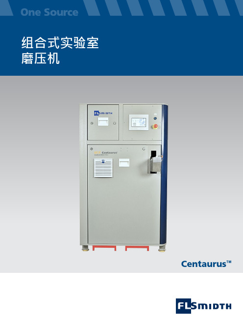
Centaurus™Centaurus ™多合一组合式磨压机独一无二的多合一自动化解决方案,可研磨和压片或者仅研磨/仅压片。
全自动制样 流程开始• 样品材料被输送到进料定量配给系统。
• 一小部分样品被送到研磨装置磨碎作为冲洗样品(清洗或盲样)。
• 丢弃冲洗样品材料• 使用专利双容积样品杯按容积进行样品计量。
• 分配研磨药片• 研磨样品• 磨碎的样品部分被输送到钢环处。
• 样品被气动液压 装置压入钢环中。
• 去除钢环样品表面的多余粉末。
• 采用真空检测确保样品制备的完整性。
• 根据配置,压片被输送到设备的前面或侧面。
• 分析后,钢环被送回进行自动清洗 和再利用。
完成每一个操作步骤后,接触过样品材料的所有内部部件表面通过压缩空气和抽吸方式联合进行清洁(除尘)。
这意味着最大程度地减少了残留样品被携带到下一个样品的情况。
灵活的基本设计允许独立式操作和多种不同方式的自动化集成,无需额外配置。
与 QCX /RoboLab 集成作为全自动样品处理的佼佼者,Centaurus 磨压机 QCX /RoboLab 在样品制备中担当主角。
当样品抵达自动接收站并装入样品杯时,机器人将样品送到 Centaurus ,这里是全自动样品制备循环的开始处。
压片从输出位置被放在通往 X 射线机的皮带上。
应用FLSmidth 的 Centaurus 自动制样机将实验室研磨和压片功能整合到一台紧凑、易操作的设备中。
该设备由一台自动精细研磨机和一台自动压片机组成。
负责这两项主要功能的部件被整合到一个符合人体工学设计的紧凑型机壳内,仅占地 1 平方米。
全自动 Centaurus 可将颗粒材料(比如生料、熟料、水泥、矿石、矿渣和矿山勘探样品)制成粉末压片试样,用于 XRF 和 XRD 分析。
自动化质量控制系统帮助改善工业制程中的产品质量。
FLSmidth 通过独有的Centaurus 制样机进一步提高产品质量。
功能Centaurus 将样品定量配给装置、自动精细研磨机和自动压片机整合到一个占地 1 平方米的隔音设备内。
KMX磨床充退磁控制器英文说明书

KMX磨床充退磁控制器英文说明书KMX-TYPE MAGNETIZING AND DEMAGNETIZING CONTROLLER FORELECTROMAGNETICSUCKING DISC OF GRINDERINSTRUCTIONXI'AN MINGSHI ELECTRO MECHANICAL DEVELOPMENT CO., LTD.1. OVERVIEWMagnetization and demagnetization have been bothering the surface grinder plants and users. The conventional magnetizing/demagnetizing method is through switch manual-control with transformation and rectification , thismethod is not only low efficiency in operation but also the magnetizing/demagnetizing effect is not obviously. Especially for the alloy or the material which was being heat treated they have a lot of residual magnetism , which affects the machining accuracy and efficiency, limited the machining range of surface grinder, Conventional magnetizing/demagnetizing method is notunsatisfy the requirement of modern machine industry for the equipment. For resolving these problems, KMX series magnetizer/demagnetizer are bedesigned and produced by XIA'N MINGSHI ELECTRO MECHANICALDEVELOPMENT CO., LTD. meticulously. It 'rsesolved above problemeffectively. The basic functions of the products are below:1. Using integrated circuit control, output without contact, reliability is high.2. The magnetizing current can be adjusted continually, it means magneticforce can adapt to different electromagnetic sucking disc of grinder formachining different workpieces.3. The demagnetizing process is automatically finished according tothe demag netiz ing curve, the effect of demag netizati on is best.4 .The demagnetizing time is adjustable.5. Aga inst over-voltage, over-curre nt and short-circuit etc.6. The main controller and the electromagnetic disc can take effect in teractaga inst un der curre nt, this fun cti on can be aga inst un der magn etism, thus the safety of operator and equipme nts can be got.7. Small size, installation and testing is convenient.2. Be selected products of KMX series which maximum output curre nt must begreater tha n the maximum rated curre nt of electromag net suck ing disc.3. CONDITION FOR NORMAL USING3.1 Ambient temperature: -10 °C 〜+40C3.2 Relative humidity: 90% )3.3 Ambience: the place for using the controllers should be away from dust related to explosion and electricity and erosive gas.3.4 Permissible voltage range: within ±10%文档仅供参考3.5 Installation: vertical, with ventilation3.6 Maximum work current is greater than 10A. It 'nsecessary toassembly an axial-flow fan into the magnetizer /demagnetizer in the designing of a new machine tool, the axial-flow fan can quick scatter the heat (especially in summer), prevent over-heat from damage.3.7 Forbid the iron powder. Dust get into the apparatus, they can result in short-circuit. Especially the grinder is under a dry grinding condition.4. INSTALLATION, ADJUSTMENT AND MAINTENANCE4.1 Requirement to electromagnetic sucking disc4.1.1 Electromagnetic sucking disc must be matched with the controler.The rated current of electromagnet sucking disc=110/interior resistance of electromagnet sucking disc.4.1.2 There is no short-circuit and open-circuit in the interior of coil.4.1.3 Insulation resistor between disc and ground (shell) must not be less than 1M Q , measured by 500V M Q multimeter.Suggestion: It 'nsecessary to add an isolating transformer in new machine tool 's designing or old machine tool s 'sertehneewing. Becau。
- 1、下载文档前请自行甄别文档内容的完整性,平台不提供额外的编辑、内容补充、找答案等附加服务。
- 2、"仅部分预览"的文档,不可在线预览部分如存在完整性等问题,可反馈申请退款(可完整预览的文档不适用该条件!)。
- 3、如文档侵犯您的权益,请联系客服反馈,我们会尽快为您处理(人工客服工作时间:9:00-18:30)。
KMX磨床充退磁控制器英文说明书
KMX-TYPE MAGNETIZING AND DEMAGNETIZING CONTROLLER FOR
ELECTROMAGNETIC
SUCKING DISC OF GRINDER
INSTRUCTION
XI’AN MINGSHI ELECTRO MECHANICAL DEVELOPMENT CO., LTD.
1. OVERVIEW
Magnetization and demagnetization have been bothering the surface grinder plants and users. The conventional magnetizing/demagnetizing method is through switch manual-control with transformation and rectification ,this method is not only low efficiency in operation but also the magnetizing /demagnetizing effect is not obviously. Especially for the alloy or the material which was being heat treated they have a lot of residual magnetism , which affects the machining accuracy and efficiency, limited the machining range of surface grinder, Conventional magnetizing/demagnetizing method is not unsatisfy the requirement of modern machine industry for the equipment. For resolving these problems, KMX series magnetizer/demagnetizer are be designed and produced by XI’AN MINGSHI ELECTRO MECHANICAL DEVELOPMENT CO., LTD. meticulously. It’s resolved above problem effectively. The basic functions of the products are below:
1. Using integrated circuit control, output without contact, reliability is high.
2. The magnetizing current can be adjusted continually, it means magnetic force can adapt to different electromagnetic sucking disc of grinder for machining different workpieces.
3. The demagnetizing process is automatically finished according to
the demagnetizing curve, the effect of demagnetization is best.
4 .The demagnetizing time is adjustable.
5. Against over-voltage, over-current and short-circuit etc.
6. The main controller and the electromagnetic disc can take effect interact against under current, this function can be against under magnetism, thus the safety of operator and equipments can be got.
7. Small size, installation and testing is convenient.
2. TYPE AND TECHNICAL PARAMETER
Note: 1. Product for special purpose can be supplied also.
2. Be selected products of KMX series which maximum output current must be greater than the maximum rated current of electromagnet sucking disc.
3. CONDITION FOR NORMAL USING
3.1 Ambient temperature: -10℃~+40℃
3.2 Relative humidity: ≤ 90% (20℃)
3.3 Ambience: the place for using the controllers should be away from dust related to explosion and electricity and erosive gas.
3.4 Permissible voltage range: within ±10%
3.5 Installation: vertical, with ventilation
3.6 Maximum work current is greater than 10A. It’s necessary to assembly an axial-flow fan into the magnetizer /demagnetizer in the designing of a new machine tool, the axial-flow fan can quick scatter the heat (especially in summer), prevent over-heat from damage.
3.7 Forbid the iron powder. Dust get into the apparatus, they can result in short-circuit. Especially the grinder is under a dry grinding condition.
4. INSTALLATION, ADJUSTMENT AND MAINTENANCE
4.1 Requirement to electromagnetic sucking disc
4.1.1 Electromagnetic sucking disc must be matched with the controler. The rated current of electromagnet sucking disc=110/interior resistance of electromagnet sucking disc.
4.1.2 There is no short-circuit and open-circuit in the interior of coil. 4.1.3 Insulation resistor between disc and ground (shell) must not be less than 1MΩ, measured by 500V MΩ multimeter.
Suggestion: It’s necessary to add an isolating transformer in new machine tool’s designing or old machine tool s’ renewing. Becau se the。
