火焰传感器使用手册
火焰探测器手册

隔爆型红外火焰探测器(IR3)安装使用说明书(Ver.1.0, 2008.04)一、概述JTGB-HW-BK51Ex/IR3隔爆型红外火焰探测器(以下简称探测器)根据GB3836.1-2000 《爆炸性气体环境用电气设备第1部分: 通用要求》,GB3836.2-2000《爆炸性环境用防爆电气设备隔爆型电气设备“d”》和GB4208-93《外壳防护等级IP代码》的规定制成防爆外壳,其防爆标志为ExdⅡCT6,适用于工厂,温度组别为T1~T6组,出现或可能出现的爆炸危险场所作为火灾探测之用。
1.1 产品特点※三重红外IR3光谱检测※防爆、防尘等级高※远距离探测※ 90度宽锥形区域侦测※实时自诊断功能※电磁辐射免疫※专利、工业化外形设计※灵敏度可调※标准4-20mA电流输出、标准RS-485接口、无源接点输出1.2 主要用途及适用范围适用于一般工业与民用建筑中火灾萌发时无阴燃阶段,突然起火的场所。
具体应用如下:化学品 --- 生产、储存、运输发电 --- 泵区、机房、无人职守区炸药和军需品 --- 储存和装卸印刷 --- 溶剂处理、压平、和干燥工艺飞机库汽车 --- 制造、喷漆房油漆 --- 制造仓库 --- 易燃品的储存石化产品 ---生产、储存、运输制药业石油天然气 --- 勘探、生产、储存海上石油平台沿海 --- 精练厂、冲装站、管道油库 ---浮动固定顶槽油库区废品处理厂 --- 易燃品加工、焚烧和储存1.3 使用环境条件a.海拔不超过1500m;b.周围环境温度-10℃~+55℃;c.周围空气相对湿度不大于95%(40±2℃);d.出现或可能出现的爆炸危险场所作为火灾探测之用;e. 无显著摇动和剧烈冲击振动的地方。
二、结构特征与工作原理2.1 外型结构图 2.1.12.2 内部结构第 3 页共 10 页图 2.2.12.3 工作原理IR3红外火焰探测器采用了三个对红外线敏感的红外传感器,对特定范围内的火灾红外辐射波长进行侦测。
火焰探测器安装使用说明书
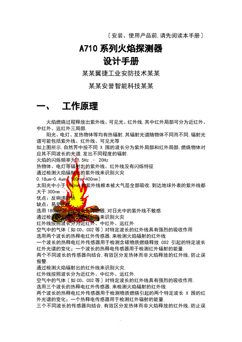
〔安装、使用产品前,请先阅读本手册〕A710系列火焰探测器设计手册某某翼捷工业安防技术某某某某安誉智能科技某某一、工作原理火焰燃烧过程释放出紫外线、可见光、红外线,其中红外局部可分为近红外、中红外、远红外三局部.阳光、电灯、发热物体等均有热辐射,其辐射光谱随物体不同而不同,辐射光谱可能包括紫外线、红外线、可见光等如上图所示,自然界中按不同X围的波长分为紫外局部和红外局部,燃烧物体对应其不同波长的光谱,发出不同程度的辐射.火焰的闪烁频率为0.5Hz – 20Hz热物体、电灯等辐射出的紫外线、红外线没有闪烁特征通过检测火焰辐射出的紫外线来识别火灾0.18um-0.4um〔180nm-400nm〕太阳光中小于300nm的紫外线根本被大气层全部吸收,到达地球外表的紫外线都大于300nm优点:反响速度快缺点:易受干扰选用180nm-260nm的紫外传感器,对日光中的紫外线不敏感通过检测火焰辐射出的红外线来识别火灾红外线按照波长分为近红外、中红外、远红外空气中的气体〔如CO、CO2等〕对特定波长的红外线具有强烈的吸收作用选用两个波长的热释电红外传感器,来检测火焰辐射的红外线一个波长的热释电红外传感器用于检测含碳物质燃烧释放CO2引起的特定波长红外光谱的变化;一个波长的热释电传感器用于检测红外辐射的能量.两个不同波长的传感器向结合,有效区分发热体而非火焰释放的红外线,防止误报警.通过检测火焰辐射出的红外线来识别火灾.红外线按照波长分为近红外、中红外、远红外.空气中的气体〔如CO、CO2等〕对特定波长的红外线具有强烈的吸收作用.选用三个波长的热释电红外传感器,来检测火焰辐射的红外线两个波长的热释电红外传感器用于检测物质燃烧引起的两个特定波长X围的红外光谱的变化;一个热释电传感器用于检测红外辐射的能量.三个不同波长的传感器向结合,有效区分发热体而非火焰释放的红外线,防止误报警.通过检测火焰辐射的紫外线和红外线来识别火灾通过增加判据,提高探测可靠性.发热物体可以辐射出红外线,一般的低温物体通常不会辐射紫外线.只有火焰既辐射出紫外线,又辐射出红外线含碳物质燃烧发出的辐射在特定波长〔4.3um〕与热物体辐射的红外线具有明显区分,根据次区分,双波长可提高红外探测的可靠性.增加紫外探测判据,更大幅度提高探测可靠性如果没有外部辐射红/紫外线的物体存在,火焰探测器没有任何的响应.同理,如果火焰探测器没有设置主动红外辐射装置,火焰探测器就难以实现污染检测.上图可以看出,同一物体发出的红外辐射能量是一样的,但是假如处于不同的辐射角度,到达红外传感敏感源的能量是不同的,其关系相当于几何上的余弦函数〔COS〕关系,例如当辐射角度为0度〔垂直辐射〕时假如辐射能量为A,如此辐射角度为60度〔斜射〕时辐射能量为cos60 *A=A/2.这就是为什么所有的红外探测器的监视X围为什么为是抛物线锥体而不是等圆锥体的原因.二、性能特点通过特定的传感器选型、火焰识别技术、软件算法,使得活火焰探测器对日光、电弧焊、人工光源、热辐射、电磁干扰等具有极强的防误报警能力.能够有效识别背景噪声,结合软件算法,对火焰辐射敏感.3.自适应、自检测功能可靠的故障自诊断,自动根据探测窗口污染情况调节探测灵敏度轴线探测距离长〔最长大60米〕、监视角度大〔120度〕,保护X围大.防尘、防水、防爆,适用于各种恶劣环境.IP65EX dII CT6,DIP A20 TA.T6<粉尘防爆>火警、故障继电器输出,方便与各种报警系统配合使用灵活的视角调节方式探测器在日常使用一段时间后,需进展清洗维护工作,一般可直接用水清洗,对存在油污等情况下可直接用酒精清洗外监视窗口,无需专人、专用工具.三、技术参数四、适用场合1. A710火焰探测器系列产品分为普通场合应用和防爆场合应用两类产品.防爆型产品均在产品外壳的标签上标注产品防爆等级参数.没有标注防爆等级的产品只能用于没有防爆要求的普通场合,不能在有防爆要求的场所使用,有防爆要求的场所必须使用带有防爆等级标志的防爆型产品.2. A710 火焰探测器标准型产品的工作温度X围为0°C -50°C,超出此工作温度X围的使用应选用温度增强型产品,增强型产品的工作温度X围为-40°C -70°C.用户需要防爆型产品和温度增强型产品须在产品订货单上明确标明.3. A710系列火焰探测器的主要适用特点A710/IR2双波长红外火焰探测器适用于无烟液体和气体火灾以与产生烟的明火火灾探测,诸如含碳材料的明火燃烧〔木材、塑料、酒精、油类产品、气体等〕,具有探测灵敏度高、保护面积大、安装使用方便、防尘、防水和抗电磁干扰等特点;不适用于对某些化学物质〔如磷、钠、镁、硫、氢等物质〕燃烧的探测.A710/UV紫外火焰探测器既可以监测碳氢化合物火焰〔汽油、丙烷、甲烷、酒精等〕也可以识别非碳氢化合物火焰〔氢气<Hydrogen>, 硅烷〔Silane〕,肼〔Hydrazine〕, 镁〔Magnesium〕等〕.但不适用在经常产生焊接弧光、电弧的场所使用,也不适于在闪电光下暴露的场合使用.A710UV/IR2火焰探测器从根本上解决了紫外传感器容易受到闪电、电焊弧光、X射线等因素影响和红外传感器容易受到工业照明、太阳光、闪烁或移动的发热物体等因素的影响而造成探测器误报警的问题,适用于有较高火焰监测要求的各种场合.A710/IR3三波长红外火焰探测器适用于无烟液体和气体火灾以与产生烟的明火火灾探测,诸如含碳材料的明火燃烧〔木材、塑料、酒精、油类产品、气体等〕,具有探测灵敏度高、保护面积大、安装使用方便、防尘、防水和抗电磁干扰等特点;不适用于对某些化学物质〔如磷、钠、镁、硫、氢等物质〕燃烧的探测.该探测器具有极高的敏感性和大X围的探测能力,而且对错误报警还有最高的免疫力.包含三个窄带红外传感器和光学过滤器,对CO2发射光谱具有最高的灵敏性.大的探测X围意味着在某些特定区域所需探测器的数量减少,能极大的节约设备和安装本钱.4.适用特殊场所和防爆场合隧道、电厂;军需品、爆炸仓库;印刷企业;硅烷;化学制品装载区;非碳氢化合物〔氢气<Hydrogen>, 硅烷〔Silane〕,肼〔Hydrazine〕, 镁〔Magnesium〕等〕生产、储运;油、气、石化产品生产厂危险品仓库以与可燃物含碳物质的其他场合等.大空间、高蓬顶建筑物体育馆、剧院、电影院、仓库、飞机库、停车场、站台、地下室等.重要物品保管场所和文化财产建筑物电脑机房、档案室、博物馆、文化遗产建筑物、数据保管库等.五、设计方案➢取决于保护场所灵敏度要求➢取决于保护场所可能出现的火源情况➢可能出现的火源类型➢可能出现的火源大小用一只探测器监视房间<适用于中等大小的空间,边长小于42米,对角线小于60米> 用两只探测器监视房间<适用于方形较大空间,最大边长小于42米、对角线距离大于60米> 用两只探测器监视房间<适用于狭长空间,窄边小于42米,长边大于42米,小于84米>用四只探测器监视房间〔适用于超大空间,最大边长小于84米,对角线距离小于120米〕正视图侧视图俯视图六、安装指导A710火焰探测器配有固定安装支架,现场安装非常方便,探测器使用24V供电,输出信号接口的标准配置为一个继电器常开触点,其他方式的接口作为可选配件提供.➢选择恰当的安装角度,防止探测盲区.考虑到被保护区域的空间结构不同,红外火焰探测器的监视X围为抛物线锥体,其轴线方向探测距离最长.因此,在安装时应将红外火焰探测器的轴线方向正对〔或背对〕被保护区的方向,这样,使得红外火焰探测器的有效监视X 围覆盖危险的探测区域,防止探测盲区.➢选择恰当的安装高度,防止因障碍物引起的探测盲区.当被保护物体具有相当高度,容易造成遮挡等情况下,因此,为防止障碍物的遮挡,应尽量提高火焰探测器的安装高度,以俯视状态监视探测区域,能够最大限度地减少障碍物造成的探测盲区.➢探测器应该对警戒区内各可能发生的火灾均保持直接入射,尽量防止间接入射和反射.➢在探测器的有效探测X围内,不能受到障碍物的阻挡,其中包括玻璃等透明的材料和其他隔离物 .6.火焰探测器的安装方式图七、设备接线1.接线端子定义,接线端子如下:,FLD为公共端、FLK为常开端、FLB为常闭端,<负载能力2A/30VDC>FRK/FRD/FRB 火警继电器的触点输出,FRD为公共端、FRK为常开端、FRB为常闭端,<负载能力2A/30VDC>GND 可复位供电电源负极﹢24V可复位供电电源正极➢所有信号线均采用Rvs-2×1.5mm线,信号电缆要走单独缆架与动力电缆隔开.➢布线施工应当严格依据设计图纸.➢导线应当穿入金属电线管.➢施工中应当注意不要将导线的外皮拉破.➢导线的连接处应当焊接,采用绝缘包装处理,也可以采用专用夹件连接.➢导线之间、导线和电线管之间的绝缘阻抗应当达到20兆欧.八、探测器灵敏度设定火焰探测器分三级灵敏度,针对由近到远的三个探测距离分别对应3级、2级、1级灵敏度.通过磁铁吸合探测器前段的灵敏度调节用干簧管,可现场调节探测器灵敏度,根据上电期间显示灯的闪烁频率,可查看当前灵敏度.标准出厂产品灵敏度设置为3级灵敏度,用户可根据现场情况修改探测器灵敏度,假如有其他灵敏度要求须在订货单上说明.九、与火灾报警系统连接火焰探测器可以任意厂家的消防火灾报警控制系统连接,通过输入模块,将火焰探测器的火警、故障等信号传送至火灾报警控制系统.如如下图所示:十、维护与保养探测器报警测试建议每个月对火焰探测器进展一次报警试验,使用专用的报警信号发生器,距离探测器探测窗口10cM的地方〔场所允许的情况下可使用打火机近距离点燃测试〕,启动报警信号发生器,探测器应该能在大约10秒钟左右报火警.探测器窗口污染清理需经常检查探测器探测窗口外表积灰和受污染情况,建议每个月对探测器镜头进展清洗,可以用酒精和清水擦洗.用户不得自行拆卸探测器,当探测器出现问题,应向供货商咨询相应的处理方法,必要时应返回生产厂家进展维护或维修.十一、故障分析、排除十二、运输、储存探测器在运输、储存、安装、调试、维护过程中要轻拿轻放,防止跌落、碰撞、挤压、摩擦等情况造成损伤.我们将尽力确保产品资料的准确和与时更新,本手册不能涵盖所有的具体应用和表现产品所有的技术特性.由于产品与技术的进步,个别细节可能变化而毋需事先通知.如需要更多或更新的资料,请联系我公司.某某翼捷工业安全公司:021-********:021-********:201204地址:某某浦东莲溪路1210号3号楼。
火焰检测传感器模块使用说明
诚信、热情、专业
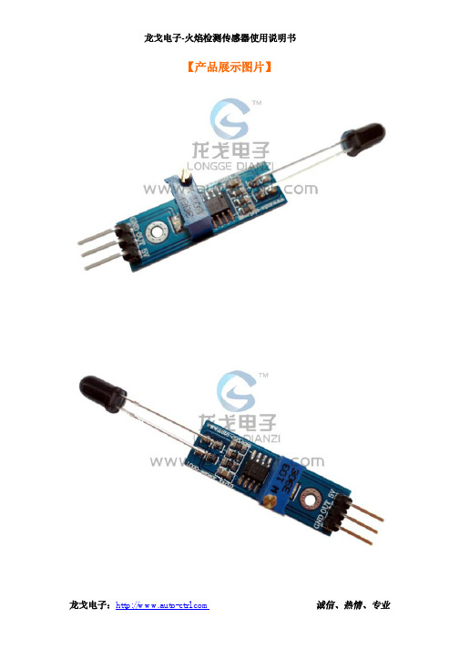
龙戈电子-火焰检测传感器使用说明书
P0 = cmd; _nop_(); _nop_(); _nop_(); _nop_(); LCD_EP = 1; _nop_(); _nop_(); _nop_(); _nop_(); LCD_EP = 0; }
void lcd_pos(BYTE pos) { lcd_wcmd(pos | 0x80); }
龙戈电子:
诚信、热情、专业
龙戈电子-火焰检测传感器使用说明书
break; }
} } void flash() {
for(i=0;i<12;i++) { delay(600); } lcd_wcmd(0x08); for(i=0;i<12;i++) { delay(200); } lcd_wcmd(0x0c);
龙戈电子:
诚信、热情、专业
龙戈电子-火焰检测传感器使用说明书
BYTE code dis2[] = {""}; BYTE code dis3[] = {" TEST...... "}; BYTE code dis5[] = {""}; BYTE code Fire[] = {"Fire "}; BYTE code Safe[] = {"Safe "};
/********************************************************************
说明:1、 当着火时,传感器输出低电平 1602 液晶显示 Fire 蜂鸣器响
2、 传感器常态时输出高电平
1602 液晶显示 Safe
FS-2000说明书

FS-2000说明书产品简介:FS-2000火焰探测器是通过探测火焰中所包含的紫外线,引发报警。
除了发出报警蜂鸣,FS-2000同其他报警装置一样具备了C(常开/常闭)继电器输出方式。
以满足各种专业的需要。
而且,机械区域调节功能可以宽范围的选择保护角度。
探测器的探头可以方便的与底座分离,这一功能使得安装和维修都很方便。
1.元件介绍wire lead(for exposed wiring): 导线槽(外线)knockout for exposed wiring:外线的穿线孔wiring hole: 走线孔base unit; 底座sensor head; 探测头detection window(sensor built-in) 探测窗(探测器内含)memory LED(yellow)blinks for 3min. after alarm then light on for 47min: 报警之后,存储记忆指示灯(黄色)闪烁3秒。
然后持续亮47分钟。
buzzer(built-in)alarm sound: sounds intermittently during offdelay 10sec:蜂鸣器(内含)报警声音,没有设置延时功能时,连续蜂鸣10秒。
alarm LED(red) blinks during offdelay 10sec:报警指示灯(红色)没有设置延时功能时,闪烁10秒。
sensor unit: 探测器terminals: 接线端子locking screw hole: 螺钉锁口release lever:释放杆front mark: 向前标记lock window: 上锁窗area locking screw:区域上锁螺钉mode setting chart: 方式设定图mode selector(buzzer, alarm memory, detection timer) 方式选择(蜂鸣,报警存储记忆,探测时间)附件:探头上锁螺钉(1个)螺杆(2个)2.注意事项提示:此探测器是用来探测火焰中的紫外线,并引发输出信号。
五路火焰传感器用户说明手册
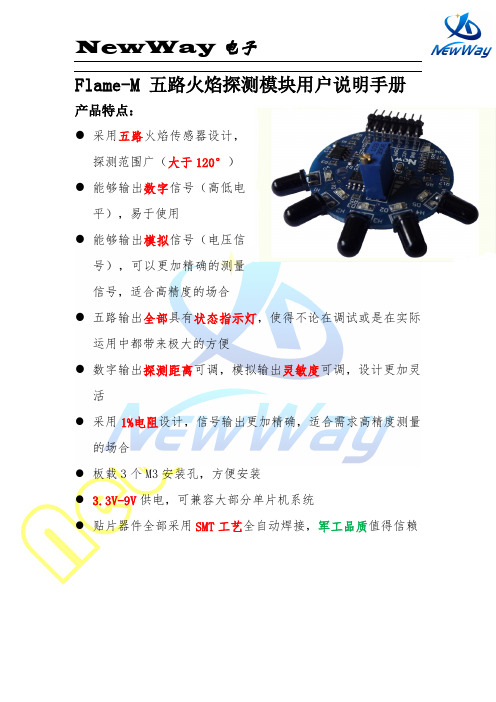
Flame-M 五路火焰探测模块用户说明手册产品特点:●采用五路火焰传感器设计,探测范围广(大于120°)●能够输出数字信号(高低电平),易于使用●能够输出模拟信号(电压信号),可以更加精确的测量信号,适合高精度的场合●五路输出全部具有状态指示灯,使得不论在调试或是在实际运用中都带来极大的方便●数字输出探测距离可调,模拟输出灵敏度可调,设计更加灵活●采用1%电阻设计,信号输出更加精确,适合需求高精度测量的场合●板载3个M3安装孔,方便安装● 3.3V-9V供电,可兼容大部分单片机系统●贴片器件全部采用SMT工艺全自动焊接,军工品质值得信赖模块原理本产品能够探测火焰发出的波段范围分别为700—1100 nm的短波近红外线(SW-NIR),通过电信号(电压信号)进行输出。
•模块接口说明信号输出口(从上到下):A1(第一个输出口既是,模块上标注为A2了): 第一路火焰传感器模拟信号输出口,随着火焰强度的增加输出电压升高D1(第一个输出口既是,模块上标注为D2了): 第一路火焰传感器数字信号输出口,高电平表示有火焰(指示灯亮),低电平标识无火焰(指示灯灭)A2: 第二路火焰传感器模拟信号输出口,随着火焰强度的增加输出电压升高D2: 第二路火焰传感器数字信号输出口,高电平表示有火焰(指示灯亮),低电平标识无火焰(指示灯灭)A3: 第三路火焰传感器模拟信号输出口,随着火焰强度的增加输出电压升高D3: 第三路火焰传感器数字信号输出口,高电平表示有火焰(指示灯亮),低电平标识无火焰(指示灯灭)A4: 第四路火焰传感器模拟信号输出口,随着火焰强度的增加输出电压升高D4: 第四路火焰传感器数字信号输出口,高电平表示有火焰(指示灯亮),低电平标识无火焰(指示灯灭)A5: 第五路火焰传感器模拟信号输出口,随着火焰强度的增加输出电压升高D5: 第五路火焰传感器数字信号输出口,高电平表示有火焰(指示灯亮),低电平标识无火焰(指示灯灭)电源接口(横排相连,随便接一个即可):VCC:模块电源正极输入口,输入范围3.3V-9V(相对于GND)GND:模块电源负极输入口距离调节旋钮:对于模拟输出:逆时针旋转(想标识增高的地方旋转),灵敏度增加,既只需要很小的输入就能得到很高的电压输出对于数字输出:逆时针旋转(想标识增高的地方旋转),探测增加,很远的距离就可以得到数字输出距离调节旋钮注意事项:5路共用一个调节旋钮技术参数探测波长:700—1100 nm探测距离:大于1.5m供电电压:3V-9V注意事项阳光对其有一定影响,使用时避开阳光使用,为减少干扰,可以在传感器端加热缩管。
火焰传感器

用途:
各种火焰,火源探测,2路继电器输出,可接220V大电流设备电器
模块特色:
1、12V电源输入专供继电器使用,板载78L05稳压三极管,提供传感器比较器用,使产品更稳定可靠;
2、可以检测火焰或者波长在760纳米~1100纳米范围内的光源,打火机测试火焰距离为80cm,对火焰越大,测试距离越远
3、探测角度60度左右,对火焰光谱特别灵敏
4、灵敏度可调(图中蓝色数字电位器调节)
5、比较器输出直接触发继电器
6、外形尺寸为:60x43mm,厚19mm,设有固定螺栓孔,方便安装
6、2路输出带蓝色接线座,接线方便
电气参数:
供电电压:12VDC
电流:大于200mA
负载:250V 10A 交流或30V 10A直流
模块使用说明:
1、火焰传感器对火焰最敏感,对太阳光也是有反应的,一般用做火焰报警等用途。
2、通过调节电位器,可以设定传感器感应火焰的强度,当火焰超过设定阈值时,继电器吸合,公共端与常开端接通,,当火焰低于设定阈值时,继电器断开,公共端与常闭端接通;
3、公共端,常开,常闭三个端口相当于一个双控开关,继电器线圈有电时,公共
端与常开端导通,无电时,公共端与常闭端导通;、
4、传感器与火焰要保持一定距离,以免高温损坏传感器,对打火机测试火焰距离为80cm,对火焰越大,测试距离越远。
HMS-FD-3IR点型红外火焰探测器用户使用手册说明书

HMS-FD-3IRRev A.1HMS-FD-3IR点型红外火焰探测器用户使用手册关于本手册 本手册将介绍如何安装和使用HMS-FD-3IR点型红外火焰探测器。
负责安装、调试、操作或维护这些产品的所有人员都应阅读本手册。
在安装该产品之前,请先阅读并完全理解本手册。
尽管我们已尽力确保本文档的准确性,但是Honeywell对任何错误或遗漏或其结果概不负责。
若能将本文档内容中的任何错误或遗漏告知我们,我们将不胜感激。
对于本文档中未包含的信息,或如需提供注释/修正,请通过背页上给出的详细联系信息联系Honeywell。
Honeywell保留更改或修订本文档中提供的信息的权利,恕不另行通知且无义务将此修订或更改通知任何人或组织。
HMS-FD-3IR用户使用手册目 录关于本手册 (2)目录 (3)一、注意事项 (4)防爆注意事项 (4)二、产品概述 (5)1、产品特点 (5)2、主要用途及适用范围 (5)三、结构特征 (6)四、技术参数 (7)1、技术参数表 (7)2、防爆要点 (7)五、接线方式 (8)1、探测器接线端子示意图 (8)2、探测器接线定义表 (8)3、灵敏度设定 (9)4、输出的自锁/非自锁设置 (9)六、探测器安装方式 (10)1、保护区域 (10)2、安装原则 (10)3、安装方式 (10)七、产品组件 (12)八、生产者 (12)一、注意事项感谢您使用HMS-FD-3IR系列火焰探测器(以下简称探测器),设备安装、操作和维护之前务必仔细阅读本说明书。
1.特别留意警告和注意事项。
2.安装过程及操作必须严格遵守国家相关标准要求。
3.探测器内部的任何操作都必须经由培训过的人员执行。
4.切勿擅自或任意拆卸传感器。
5.不得将传感器置于超建议范围的温度下。
6.不得将传感器置于有机溶剂或可燃性液体中。
7.传感器使用期限达到时,应从环保的角度,依照地方废物管理以及环境法规的要求进行安全处理。
或退回我公司进行集中的无害化处理。
FSSS火焰监测系统(COEN)用户手册

图11RS232 / RS485转换器………………………………………………………………A9
图12光纤…………………………………………………………………………………A10
图13光纤的典型尺寸………………………………………………………………………A10
ISCAN火焰监测器将监测头和信号处理器设计为一体。无需二次信号处理器或放大器。一体化的火焰监测器减除了绝大部分的安装成本,不再需要放大器柜,放大器组件,预制电缆及现场布线。
ISCAN火焰监测器是以微处理机为基础,采用了最新的固态信号处理技术。运用固态光学传感器探测火焰的存在与否。可同时探测紫外及红外光谱。
2.安装
注:此章节仅适用于基本型和危险区型,光纤型的安装请看见附件F。
2.1火焰监测器安装及冷却风连接
ISCAN火焰监测器有一个1”NPT(F)安装接头。建议使用可旋转型火焰监测器安装件,以便能够进行火焰监测器视线调节。
如使用刚性安装件,请按照2.2所述,在完成初始视线调节后,将火焰监测器固定件临时焊在固定位置,在火焰监测器的视线调节最终确定后再将火焰监测器固定件最终焊接到位。
7. 1设置/程序……………………………………………………………………………27
7. 2浏览火焰监测器文件………………………………………………………………28
7. 3火焰频率……………………………………………………………………………29
7. 4火焰信号……………………………………………………………………………30
4.冷却风压力为火焰监测器冷却风进口与风箱之间的最小压差。
5.Coen的专利(美国专利号48231114)。电子辅助视线指示器位于火焰监测器探头的背部,
三频火焰探测器说明书

警示: 除了 DIP 开关,不要触摸内部元件(静电敏感装置(ESD)参考附件 A)
继电器 Phoenix 使用两组 DIP 开关 DIP 开关 #1 用于定义敏感性和延迟时间 DIP 开关#2 用于定义继电器设置;它只能用于继电器模式,并且只有位置 2 是可以用的。 见表格 7 和 8. 模拟 模拟(无继电器)Phoenix 只使用 DIP 开关#1 来定义敏感性和延迟时间的设置。DIP 开 关使用说明见表 7.
导线须使用外壳和保护层来使得每根导线周围都有密封。这能防止空气,气体和水从外壳的 里面泄漏到外罩的外面。
建议使用防爆排管和通透导管。温度和大气压的变化会导致‘渗透’使得水蒸汽进入导管。 连接头不足以防止通透渗漏。
连接 Phoenix 可以是模拟,模拟/数显,继电器或数显模式。各种模式的特定链接参考以下表格。 有需要的话,终端接线盒也可以由 Net Safety 提供。
功能 接地 Vdc (+) Com (-) 绝缘电源(+) 4-20mA 信号输出
功能 接地(GND) Vdc (+) Com (-) 报警继电器 报警继电器 故障继电器 故障继电器
警示: 如果在 Net Safety 多功能接线盒中制作了终端口,特殊终端设计请参考 MAN-0081
注意: 当和模拟/继电器接线盒(JB-IR3SAR-A/S)一起使用模拟装置(IR3S-A), 能使用 外置磁铁来重新设置和接线盒连接在一起的报警。 使用说明书见 MAN-0081。
零延迟时间只能用在须即时作出反应,控制地非常好,并且允许产生少量误报警的应用中。
延迟时间设为 3,5,10 秒 延迟时间设置是指探测器在发出火焰报警之前,火焰信号必须持续出现的时间长度。 当火 焰持续至设定的延迟时间,报警会在 5 秒之内发出。这一延迟到 5 秒的设置是用户不能自己 调节的。
TL105 型火焰探测测试灯使用说明书
The information and technical data disclosed inthis document may be used and disseminatedonly for the purposes and to the extentspecifically authorized in writing by GeneralMonitors.Instruction Manual 12-15General Monitors reserves the right to changepublished specifications and designs withoutprior notice.MANTL105Part No.MANTL105M odel T L105Test Lamp for Flame DetectionThis page is intentionally left blank.NOTE THIS IS YELLOW PAPERWARNING: Do NOT leave battery uncharged. It will result in permanent battery damage.Page intentionally left blankTable of ContentsMODEL TL105 (I)TEST LAMP FOR FLAME DETECTION (I)ABOUT THIS MANUAL (VIII)Format Conventions (viii)Notes, Cautions, and Warnings (viii)Contacting Customer Support (viii)1.0INTRODUCTION (9)1.1Notice (9)1.2Special Warnings (9)1.3Description (9)1.4Upon Receiving (9)1.5Test Lamp Operating Principle (11)2.0QUICK START GUIDE (12)3.0TEST LAMP COMPONENTS (13)3.1Lamp Housing Assembly (13)3.2Microcontroller (13)3.3Rotary Switch Setting (13)3.4Rechargeable Battery (13)3.5Power Jack (13)3.6Push Button (13)3.7Aluminum Case and Cap (14)3.8Battery Charge State Indicator (14)4.0USE AND OPERATION (15)5.0TEST LAMP MAINTENANCE AND WARRANTY (18)5.1Maintenance (18)5.2Cleaning the Sapphire Window (18)5.3Recharging the Battery (19)5.4Obtaining Service (19)5.5Warranty (19)6.0TROUBLESHOOTING GUIDE (21)CUSTOMER SUPPORT (22)7.0 227.1Other Sources for Help (22)8.0APPENDIX (23)8.1Specifications (23)8.2Regulatory Agency Approvals (23)8.2.1Regulatory Agencies (23)8.2.2Classification Area and Protection Methods (24)Table of FiguresFigure 1: TL105 Test Lamp (9)Figure 2: TL105 Battery Connection (10)Figure 3: Approximate Distance between TL105 and a Flame Detector (12)Figure 4: Reflector Mounting in Body (15)Figure 5: Location of Functional Board under Lamp Assembly (16)Table of TablesTable 1:Charge State Indicator (14)Table 2: Detector Test Mode Initiation or/Detector Alarm Trigger with TL105 (17)Table 3: Troubleshooting Table (21)Table 4: Locations (22)About This ManualThis manual provides instructions for operating, and maintaining the General Monitors (GM) TL105 test lamp. The intended audience includes installation personnel, field service technicians, and other technical staff involved in using a TL105.Format ConventionsSeveral format conventions are used throughout this manual for Notes, Cautions, and Warnings. These conventions are described below.Notes, Cautions, and WarningsNOTE: Notes provide supplementary details such as exception conditions, alternate methodsWARNING:These notices describe precautions to prevent hazardous conditions that may cause injury to people working with the equipment.Contacting Customer SupportFor additional product information not contained in this manual, please contact General Monitors Customer Support. Refer to Section 1.0 for contact information.1.0 IntroductionFigure 1: TL105 Test Lamp1.1 NoticeAll information contained in this instruction manual applies only to the setup and operation of the TL105 test lamp with flame detectors provided by General Monitors. The sale of the test lamp does not license the user to reproduce GM drawings or to utilize any information contained in this manual without prior written permission.The TL105 test lamp is easy to set up and operate. However, this manual should be read in full, and the information contained herein understood, before attempting to operate the test lamp in service.1.2 Special WarningsWARNING: Do NOT leave battery uncharged. It will result in permanent battery damage.UV light is injurious to one’s vision. Do not stare into functioning lamp. Wear eyeprotection of UV blocking glasses to prevent eye injury.Do not attempt to recharge the TL105 in areas where combustible gases orpotential explosive gases are located.1.3 DescriptionThe TL105 is a battery operated rechargeable test lamp specifically designed to test General Monitors’ UV, U V/IR, Digital Frequency IR, and Multi-Spectral IR flame detectors. The test lamp provides a high-energy, broadband radiation source that emits sufficient energy in both the ultraviolet and infrared spectra to activate UV and/or IR detectors. To simulate the flickering ofa fire, the test lamp automatically flashes at various selectable rates.1.4 Upon ReceivingTL105 Lamp leaves the factory with the battery disconnected. The customer must connect andfully charge the battery before use. If you connect the battery and activate the push button, the RED LED will stay on for 60 seconds. It will continue to do so until the battery has been fully charged.Since the TL105 goes to fault mode when a charger is plugging in and no battery is present, you must plug in the battery before the charger.Make sure to keep the lens and the reflector is kept clean from debris and fingerprints. Grease on the window will absorb the required energy from reaching the flame detector.Please follow the steps outlined below to connect the battery:∙Loosen the Set Screw on the Cap.∙Unscrew the Cap counterclockwise and remove it from the Body.∙Remove the two screws holding Reflector on the Body.∙Pull the Reflector off to reveal a 4-Pin Connector on the PC Board.∙Plug the 4 wire Connector coming from the Body into the 4 -Pin Connector on the PC board. The pins on the connector align one way only.∙Reposition the Reflector on the Body and tighten 2 screws to hold the Reflector on the Body.∙Reinstall the Cap to the TL105 Body by screwing it on clockwise.∙Tighten the Set Screw on the Cap.∙Follow Section 5.3 in the TL105 Instruction Manual to recharge the battery.NOTE: If replacing the battery, it is first required to remove the retainer plate prior to removal of the battery. Ensure the battery retainer plate is reinstalled prior to reassembling the unit.Figure 2: TL105 Battery Connection1.5 Test Lamp Operating PrincipleA variety of flashing test patterns, selectable through a rotary switch, allows the test lamp to check the operation of General Monitors flame detectors. When the specific flashing pattern for a given type of flame detector is appropriately selected, the test lamp triggers the alarm or test mode. Please refer to Table 2 for rotary switch settings.2.0 Quick Start GuideFigure 3: Approximate Distance between TL105 and a Flame DetectorIt is important to begin a series of flame detector checks with a fully charged TL105.∙Stand between 10 and 35 feet from a Flame Detector that is to be tested and aim the TL105 directly into the detector window. ∙Press the ON button and be sure the high intensity pulsing beam strikes the detector face squarely. ∙ On some Flame Detectors shaking the lamp from side to side or up and down may increase the simulation of flame flicker and improve the response of the flame detectorto the lamp.∙When the Flame Detector senses the Test Lamp, the red LED will blink slowly. Thegreen light may also blink. After a time delay the red LED will start to blink quickly.This signifies the completion of the test. NOTE: Please refer to Table 2 for maximum distance to each detector.NOTE: The TL105 triggers a Flame Detector into alarm. The system must be disabled duringtest if you do not want false trips.To conserve charge, do not operate the test lamp longer than is necessary to test a Flame Detector.When the battery level drops below the level required to maintain the proper intensity of the lamp, an internal low voltage circuit will shut the lamp off until the battery has been recharged. Please refer to Section 5.3 for complete recharging instructions.It is mandatory that the TL105 be kept on charge when not in use to prevent excessive battery discharge. The batteries may be charged an average of 500 times before the battery pack is replaced.NOTE: Please refer to Section 3.8 for Battery Charge State Indicator details.NOTE: Please refer to Section 5.3 for detailed information on Recharging the Battery. Thenormal recharge time for the rechargeable battery is 3.5 hours.10-35 ft3.0 Test Lamp Components3.1 Lamp Housing AssemblyNOTE:Do not put fingerprints on the reflector or the light bulb, as this will reduce the available radiation required by the individual detector.The lamp housing assembly consists of a gold-plated parabolic reflector with the lamp affixed to its center. A light emitting diode (LED) that serves as a battery charge indicator is also housed near the edge of the reflector.3.2 MicrocontrollerThe TL105’s flashing patterns are controlled by a microcontroller. This device also monitors battery voltage and shuts down the flash lamp output when the battery charge is low. The microcontroller resides on the functional board.3.3 Rotary Switch SettingA rotary switch is used to configure the test lamp to function with FL3XXX, FL4000, FL4000H, and Type V UV and Type VI UV/IR detectors. Positions of the rotary switch for each of these detectors are noted in Table 2 and are labeled next to the rotary switch inside the lamp. The rotary switch resides on the functional board. (Do not operate the TL105 in factory mode. Damage may result to the TL105)3.4 Rechargeable BatteryThe TL105 test lamp is powered by a 12V rechargeable battery. It is mandatory to keep the test lamp docked with its battery charger when the test lamp is not being used. This will increase the expected life of the battery and will always keep the test lamp available for immediate use. WARNING: Do not leave battery uncharged. It will result in permanent battery damage.NOTE:The normal recharge time for the rechargeable battery is 3.5 hours.3.5 Power JackThe power jack is located directly under the aluminum cap and can be accessed when the cap is removed. The cap must always be in place when operated in a hazardous location. An Allen wrench is included with the test lamp to unscrew or affix the plug. With the plug removed, the battery can be recharged by connecting the jack to the TL105 battery charger. The battery charger operates from a 110 – 240 VAC power line.3.6 Push ButtonThe push button toggles the lamp ON or OFF. Press the button once to turn the lamp on, and press it again to turn the instrument off. After flashing for a maximum of 5 minutes, the testlamp will turn itself off. This is to prevent the battery becoming completely discharged if the ON / OFF button is accidentally bumped on.3.7 Aluminum Case and CapThe TL105 red aluminum housing is explosion proof for use in hazardous locations (8.2.2). Itcan also be used for general-purpose, non-hazardous applications.3.8 Battery Charge State IndicatorThe tri-color LED affixed to the gold parabolic reflector displays the charge state of the battery. The flashing patterns and colors of the signals are shown in Table 1.Table 1:Charge State IndicatorNOTE: The TL105 attempts to detect improper chargers. However it can not detect all improper chargers, care must be used to ensure the proper charger is used.If the improper charger is used, disconnect the charger and wait 1 minute until the red LED goes out before connecting the proper charger.4.0 Use and OperationFigure 4: Reflector Mounting in BodyPrior to opening of the test lamp make sure that the set screw located on the cap is loosened sufficiently to remove the cap.When closing, make sure that the captive screws (located on the reflector) are matched with the holes located on the body of the test lamp.Before beginning a flame detector check, adjust the rotary switch setting in the TL105 test lamp according to the type of GM flame detector used. Table 2 shows the rotary switch configurations for GM flame detectors FL4000H, FL4000, FL3XXX, and Types V and VI. Usinga fully charged TL105, stand up to the distance specified in Table 2 from the flame detector tobe tested and aim the TL105 directly into the detector window. Press the ON button and ensure the high intensity intermittent beam strikes the detector face. If the system is operating normally, the instrument will go into a warning condition after a few flashes of the test lamp. If the lamp remains on for the period set by the time delay adjustment, the Flame Detector will go into alarm1.1For test initiation with the FL4000/FL4000H flame detector, please refer to the FL4000/FL4000H Instruction Manual.of the detector. When using the test lamp in conditions of frost, make sure that the lens is free of frost and ice. A plastic card can be used without scratching the lens cap to remove frost build-up.NOTE: Recharging the battery and normal docking of the test lamp when not in use ismandatory. This will extend the useful life of the battery and also make the test lamp available for immediate use. Normal rechargetime is approximately 3 hours; the maximum recharge time is 3.5 hours.NOTE : Location of the rotary switch in the TL105 control board, shown in Figure 5.Table 2: Detector Test Mode Initiation or/Detector Alarm Trigger with TL1055.0 Test Lamp Maintenance and Warranty5.1 MaintenanceRoutine maintenance for the test lamp is minimal:∙When the test lamp is not being used, it is mandatory to ensure that the test lamp is docked on the charger and the charger is connected to a live 110 –240VACpower supply adapter. Permanent battery damage will occur if not charged for 60days.∙Make sure that the test lamp lens is free of frost or large accumulations of moisture during frosty conditions or inclement weather.∙The battery life will be affected by extreme temperatures. Store and charge the battery between +5°C and +30°C (+41°F and 86°F) if possible.There are no user serviceable parts inside the test lamp besides the battery pack. After a number of years, the battery may fail. This will be indicated by a flashing red indicator at the front of the lamp. The unit should be returned to General Monitors for a replacement battery or a replacement battery pack may be ordered from General Monitors. See section 1.4 for battery replacement instructions. If the test lamp is to be discarded, the battery must be recycled at this point.In most countries it is illegal to dispose of the battery with other garbage. General Monitors has a Recycle Program in place to recycle the used batteries.NOTE: The removal of particulate matter and any film buildup on the Sapphire Window is necessary to ensure proper sensitivity of the system. It is recommended that thewindow be cleaned at least every 30 days if the detector is located in a particularly dirtyenvironment.5.2 Cleaning the Sapphire WindowA clean, soft, lint-free cloth, tissue or cotton swab should be used to apply the cleaning solution. The window is not glass; it is made from sapphire. The cleaning solution should be General Monitors P/N 10272-1 (Industrial Strength Windex® with Ammonia D).Do not touch the window with fingers.1. Wet the window with the solution.2. Rub with a dry, unsoiled cloth until the window is clean.Do not use a commercial glass cleaner other than Industrial Strength Windex® withAmmonia D.5.3 Recharging the BatteryBefore the lamp is used for the first time, or after it has been used to the point where the red LED at the front has come on solidly, the battery must be recharged. To recharge the battery, take the test lamp to a non-hazardous area where there is no possibility of an explosive gas or dust atmosphere being present. The temperature in this area must be between 32°F (0°C) and 104°F (40°C). No damage will occur if the unit is outside the temperature range, but the battery will not charge.Use an Allen wrench to remove the charging plug stopper and connect the General Monitors Switching Power Supply P/N 71676 to the charging socket exposed by removing the charging stopper.Plug the Switching Power Supply into an electrical outlet between 100 and 240 VAC 50 to 60 Hz rated to provide at least 1.5 A. The charge indicator LED at the front of the test lamp will change to the color yellow to show that the battery lamp is charging. When the charge is complete (less than 3.5 hours), the charge indicator will change to green. If the lamp is to be stored, leave it connected to the Switching Power Supply to keep the battery charged.Before using the test lamp, unplug the charging connector from the test lamp, carefully insert the charging plug stopper using an Allen wrench and screw it all the way into the hole. Do not over-tighten the stopping plug. The lamp can now be safely used in hazardous locations as specified on the test lamp nameplate and in Section 8.2.2 of this manual.5.4 Obtaining ServiceThe TL105 test lamp contains no user serviceable parts besides the battery pack. To obtain information regarding factory service, contact General Monitors or your General Monitors representative. Please have the following information available:∙Instrument model number (on the nameplate)∙Instrument serial number (on the nameplate)∙Description of the problemThere are no user serviceable parts inside the Model TL105 test lamp. Workperformed by persons not authorized by General Monitors will void the warranty. from defects in workmanship or material under normal use and service within two (2) years from the date of shipment.General Monitors will repair or replace without charge any equipment found to be defective during the warranty period. Full determination of the nature of, and responsibility for, defective or damaged equipment will be made by General Monitors’ personnel.Defective or damaged equipment must be shipped prepaid to General Monitors or the representative from which shipment was made. In all cases, this warranty is limited to the costof the equipment supplied by General Monitors. The customer will assume all liability for the misuse of this equipment by its employees or other personnel.All warranties are contingent upon proper use in the application for which the product was intended and do not cover products which have been modified or repaired without General Monitors’ approval or which have been subjected to neglect, accident, improper installation or application, or on which the original identification marks have been removed or altered. Except for the express warranty stated above, General Monitors disclaims all warranties with regard to the products sold, including all implied warranties of merchantability and fitness and the express warranties stated herein are in lieu of all obligations or liabilities on the part of General Monitors for damages including, but not limited to, consequential damages arising out of / or in connection with the use or performance of the product.6.0 Troubleshooting GuideThe following table lists potential problems that can affect the test lamp circuit. Follow the individual steps to pinpoint and define circuit ailments.This section is intended to be a guide in correcting problems, which may arise in the field. General Monitors should be contacted for assistance if the corrective action listed does not eliminate the problem.Table 3: Troubleshooting Table7.0 Customer SupportTable 4: LocationsAdditional locations can be found on our web site, 7.1 Other Sources for HelpExtensive documentation, white papers, and product literature for our complete line of safety products can be found at /detection8.0 Appendix8.1 SpecificationsElectrical specification 12 VDC 130 W MaxOperating temperature: 5°F to +122°F (-15°C to +50°C)Storage temperature: 5°F to +122°F (-15°C to +50°C)Charging temperature 32°F to +104°F (0°C to +40°C)Humidity range: 10% to 90% ± 3% RH, non-condensingWeight: 7.9 lb (about 3.5 kg)Dimensions: 13” L x 5” D (330 mm L x 127 mm D)Approvals: CSA, ATEX, IECEx and CE MarkCharging time: 3.5 hoursOutput spectra: Broadband emissions in UV, visible and IRCharger input: 110 –240VAC,50/*********Output: **********Detection range: See Table 2 for maximum distance per flamedetector model.8.2 Regulatory Agency Approvals8.2.1 Regulatory AgenciesThe TL105 is certified by the following regulatory agencies:∙ATEX / IECEx – Hazardous Locations∙Canadian Standards Association (CSA) – Hazardous Locations8.2.2 Classification Area and Protection MethodsThe TL105 is certified as follows:∙Protection Methods Ex d IIB+H2 T4GbEx tb IIIC T110°C Db∙Area Classification Class I, Division 1 and 2, Groups C and D∙Conforms With Electromagnetic Compatibility Directive (2014/30/EU) PLEASE NOTE:The following instructions apply to equipment covered by the ATEX / IECEx certificates: ∙The equipment may be used in environments containing flammable gases and vapors with equipment group IIB+ H2 and temperature class T4 or inenvironments containing flammable dusts with equipment group IIIC and amaximum surface temperature of 110°C.∙The equipment is only certified for use in ambient temperatures in the range -15o C to +50o C (5°F to +122°F) and should not be used outside this range.∙Installation shall be carried out by suitably-trained personnel in accordance with the applicable code of practice e.g. EN/IEC 60079-14.∙Inspection and maintenance of this equipment shall be carried out by suitably trained personnel in accordance with the applicable code of practice e.g.EN/IEC 60079-17.∙Repair of this equipment shall be carried out by suitably trained personnel in accordance with the applicable code of practice e.g. EN/IEC 60079-19.∙The flameproof joints are other than the minimum or maximum values detailed in EN/IEC 60079-1.EU Member states shall dispose according to WEEE regulations. For further WEEE disposal。
火焰传感器用户手册(电压输出型)
模拟电压输出火焰传感器使用手册非常感謝您選用碩鋒科技产品,为了您正確使用,請在使用前仔細閱讀本說明書,並妥善保存以供今後參考前言歡迎使用碩鋒科技產品,希望此說明書在您使用過程中給您帶來方便,我們在編寫本傳感器手冊時,已盡力確保手冊中的內容沒有缺點,如果您在手冊中發現有任何不清楚、錯誤或過於冗長的地方,請及時與代理商或公司總部聯繫。
注意①在使用前,請認真閱讀每項內容。
②禁止在任何未經許可的情況下,傳播本手冊中的內容。
③本手冊僅為提供有關信息,手冊中所有內容會在不經通知的情況下修改。
④除非手冊中已經說明,否則,請不要將本產品加以改造或者修正,如果未經允許而私自加以改造或者修正,以導致本產品損壞,本公司將採取有償服務。
- 2 -主要研究方向:◆高精度倾角传感器◆数字罗盘、数字指南针◆无线数字传感系统◆仿生感知机器人与控制研究◆履带研究版机器人机械动力结构设计◆轮式教学机器人研究- 3 -- 4 - 一、功能介绍:远红外传感器又称之为火焰传感器,主要用于检测火源的位置和大致判断距离的远近,例如在灭火比赛中判断火源的远近等。
序号 项目 技术参数 备注 1 VCC 电源正 2 GND 电源地3 信号线 模拟电压输出4 尺寸 不含探头和插针5 工作电压 DC 3-5.5V6 灵敏度调节 有7 输出方式 模拟电压输出 需要经过AD 转换接到单片机8 功耗小于20mA二、特点:1、模拟电压输出。
2、模块带安装孔,方便固定安装;3、用于检测波长在760纳米~1100纳米范围内的远红外热源;4、探测角度达60度;5、传感器距离火源越近,输出电压越小。
- 5 -例如机器人上可以采用了3只远红外传感器(700nm-1000 nm )构成红外传感系统,主要用来检测前方、左前方和右前方的热源,检测距离范围为0~1m 。
用户可以通过调节电位器来调节远红外传感器灵敏度。
远红外传感器将外界远红外光的变化转化为电流的变化,在电阻上产生电压,我们可以通过A/D 转换器反映为0~1023范围内的数值。
火焰光度计使用方法说明书
火焰光度计使用方法说明书一、前言火焰光度计是一种用于测量火焰强度和光谱信息的仪器。
本使用方法说明书旨在向用户提供详细的操作指南和注意事项,以确保正确且安全地使用火焰光度计。
二、器材准备1. 火焰光度计主机及相关附件2. 电源线或电池组3. 标准火焰源4. 笔记本电脑或数据采集系统(可选)三、操作步骤1. 准备工作a) 确保火焰光度计主机和附件完好无损。
b) 确认电源线或电池组的电量充足。
c) 准备标准火焰源,并确保其稳定燃烧。
2. 连接电源a) 若使用电源线供电,请将其正确插入火焰光度计主机的电源接口。
b) 若使用电池组供电,请将电池组正确安装至火焰光度计主机的电池槽。
3. 主机开机a) 打开火焰光度计主机的电源开关。
b) 确认主机屏幕上显示正常,显示界面无异常现象。
4. 连接标准火焰源a) 使用专用连接线将标准火焰源与火焰光度计主机连接。
b) 确保连接牢固,无松动。
5. 光度计校准a) 在主机操作界面上选择校准功能,并按照界面提示进行操作。
b) 确保校准过程中环境光线较暗,并确保标准火焰源的光谱特性与仪器的校准参数相匹配。
6. 测试测量a) 在主机操作界面上选择测量功能。
b) 将火焰光度计指向待测火焰,并保持适当的距离和角度。
c) 等待一段时间,直到主机屏幕上显示出火焰强度和光谱信息。
7. 火焰光度计移除a) 关闭火焰光度计主机的电源开关。
b) 断开标准火焰源与火焰光度计主机的连接。
c) 若使用电源线供电,请将电源线拔出主机的电源接口。
d) 若使用电池组供电,请将电池组从主机的电池槽中取出。
8. 关机及保养a) 将主机屏幕显示恢复至初始界面,并关闭电源开关。
b) 清洁火焰光度计主机外壳,使用干净而柔软的布进行轻柔擦拭。
c) 将火焰光度计主机及配件存放在干燥通风的地方,避免阳光直射和潮湿环境。
四、注意事项1. 在使用前,请阅读并理解本使用方法说明书,并按照说明书的操作步骤进行操作。
2. 火焰光度计主机及附件应由专业人员进行安装和维修,非专业人士请勿擅自拆卸或维修。
罗威(ROVAR)火焰探测器 FLAMEVision系列产品手册说明书

The FLAMEVision family of flame• Operator verification The optional built-in videocamera assists operator verification and ensuresoptimum actions are taken. Additional benefit of postevent analysis and to aid and verify alignment• Optimum protection in all weather conditions• FLAMEVision maintains sensitivity using theenhanced IR sensors through heavy rain, snow, fogand morning dew• Use in Hazardous explosive atmospheres• F LAMEVision is approved for protection regardless ofarea classifications for all applications throughout thefacility• Reduced spares inventory and simpler maintenance• I ntrinsically safe, low cost and easy to use testequipment simplifies maintenance and reducesTechnical SpecificationsMechanical - DetectorDimension: 156 mm H x 155 mmW x 99 mm DWeight : 4 kgGland entry: 2 x M20Material: Stainless steel 316L, ANC4BFCLC to BS3146: Part 2Guard/label plate: Stainless steel 316S16 to BS1449: Part 2Screws external: Stainless steel 316 A4 Detection window: SapphireCamera window: Toughened glass Mechanical - BracketDimension: 181 mm H x 125 mm Wx 95 mm DMaterial: Stainless steel 316S16 to BS1449: Part 2Weight: 1.54 kgEnvironmentalOperating temp: -40°C to +80°CStorage temp: -40°C to + 80°COperating temp of camera:-10°C to +50°CStorage temp with camera:-20°C to + 70°C(operating temperature isreduced for T5 risks) Relative humidity : 99% (non condensing) Enclosure: IP 66Flameproof certification:ATEX Ex II 2 G D , IECEx & FMEN54 ApprovalCPR EN54-10:2002 + A1:2005FV400 is classified as Class 1 on the Extended and Nor-mal range settings.FV400 is certified as Class 3 on the Half range setting. FV300 is classified as Class 1Camera SpecificationComposite video: (1 V p-p) into 75 Ohm viatwisted pair balum Horizontal resolution: Standard 450 TVLLight sensitivity (-30 IRE): 0.3 Lux*1 Installation manual should be consulted for specific applications.*2 Feature under implementation.*3 FV421i is not available with a relay output,camera and heater options.Detector performanceMax Range (0.1m² n heptane): FV400 65 m, FV300 50 m*1 Field of view: 90° horizontal, 85° vertical InterfacesFV300Modbus4-20 mA Sink or sourceFire & fault relay contacts NO or NC*Composite video o/pFV400Modbus4-20 mA Sink or sourceConventional detector I/FTyco MZX DigitalFire & fault relay contacts NO or NCComposite Video o/p (Camera option only)HART interface *2ElectricalFV300Supply voltage: 20 to 30 VdcCurrent consumption (max):196 mA quiescent, 205 mAAlarm (24 Vdc)Heater: 90 mA@24vdc Connections: 2.5 mm2 (14AWG) Terminals FV400Supply voltage: 18 to 30 VdcCurrent consumption: 8 mA quiescent 20 mA Alarm(24 Vdc - interface dependant) Camera: 85 mA@24 VWindow Heater: 245 mA @ 24 VExternal supply required only for camera, heater or MOD-BUS optionsConnections: 2.5 mm2 (14AWG) Terminals FV421iSupply Voltage: 18 to 28VCurrent consumption: 1.5mA quiescent, 6ma Alarm(24V, Interface dependent).Please refer to the appropriate technical manuals when utilising any of the Flame Vision range for specific applications and installations.。
火焰检测器使用手册说明书
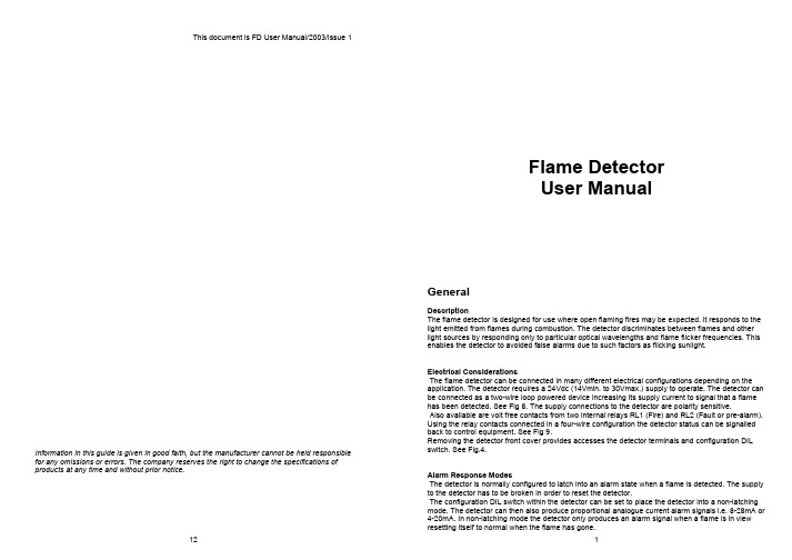
This document is FD User Manual/2003/Issue 1Flame DetectorUser ManualGeneralDescriptionThe flame detector is designed for use where open flaming fires may be expected. It responds to thelight emitted from flames during combustion. The detector discriminates between flames and otherlight sources by responding only to particular optical wavelengths and flame flicker frequencies. Thisenables the detector to avoided false alarms due to such factors as flicking sunlight.Electrical ConsiderationsThe flame detector can be connected in many different electrical configurations depending on theapplication. The detector requires a 24Vdc (14Vmin. to 30Vmax.) supply to operate. The detector canbe connected as a two-wire loop powered device increasing its supply current to signal that a flamehas been detected. See Fig 8. The supply connections to the detector are polarity sensitive.Also available are volt free contacts from two internal relays RL1 (Fire) and RL2 (Fault or pre-alarm).Using the relay contacts connected in a four-wire configuration the detector status can be signalledback to control equipment. See Fig 9.Removing the detector front cover provides accesses the detector terminals and configuration DILswitch. See Fig.4.Information in this guide is given in good faith, but the manufacturer cannot be held responsiblefor any omissions or errors. The company reserves the right to change the specifications ofproducts at any time and without prior notice.Alarm Response ModesThe detector is normally configured to latch into an alarm state when a flame is detected. The supplyto the detector has to be broken in order to reset the detector.The configuration DIL switch within the detector can be set to place the detector into a non-latchingmode. The detector can then also produce proportional analogue current alarm signals i.e. 8-28mA or4-20mA. In non-latching mode the detector only produces an alarm signal when a flame is in viewresetting itself to normal when the flame has gone.• • • • • • • Application for Flame DetectorsFlame detectors are used when detection is required to be:Unaffected by convection currents, draughts or wind Tolerant of fumes, vapours, dust and mist Responsive to a flame more than 25m away Fast reactingThe detector is capable of detecting the optical radiation emitted by burning material even non-carbonaceous materials. e.g. HydrogenNumerous other potential fire sources can be detected such asLiquids Solids Gases ● Aviation Fuels (kerosene) ● Coal ● Butane ● Ethanol ● Cotton ● Fluorine ● Methylated Spirits ● Grain & Feeds ● Hydrogen ● n-Heptane ● Paper ● Natural Gas ● Paraffin ● Refuse ● Off Gas ● Petrol (gasoline) ● Wood ● PropaneTypical applications examples are:● Agriculture ● Coal handling plant ● Pharmaceutical ● Aircraft hangars ● Engine rooms ● Power plants ● Atria ● Generator rooms ● Textiles ● Automotive industry ● Metal fabrication ● Transformer stations - spray booths ● Paper manufacture ● Waste handling - parts manufacture ● Petrochemical ● WoodworkingApplications and Locations to Avoid:● ambient temperatures above 55°C ● large IR sources – heaters, burners, flares ● close proximity to RF sources ● obstructions to field of view ● exposure to severe rain and ice ● sunlight falling directly on the detector optics ● large amounts of flickering reflections ● spot lighting directly on the detector opticsQuantities Required and Positioning of DetectorsThe number of detectors required and their position depends on:the anticipated size of the flamethe distance of the flame from the detector the angle of view of the flame detectorThe flame detector is designed to have a class 1 performance as defined in BS EN54-10:2002 on the high sensitivity setting. That is the ability to detect an n-heptane (yellow) fire of 0.1m² or methylated spirit (clear) fire of 0.25m² at a distance of up to 25m within 30 seconds.The detector can be set to have to a lower sensitivity setting equivalent to class 3 performance. Class 3 performance is defined as detecting the same size fires as for class 1 but at a distance of only 12m.Functional TestingWhen 24Vdc power is applied to the detector the green supply on indicator LED will illuminate. The fault relay RL2, if selected with the DIL switch, will energise and the contact between terminals 7 and 8 will close. If 24Vdc is applied to terminals 3 and 4 or terminal 3 is linked to terminal 1 the detector will perform a self-test. It does this by causing internal optical test sources to simulate the behaviour of flames and the detector will alarm. Alternatively a portable flame sensor test unit is available to generate simulated flame behaviour and test the detector a few metres in front of the detector. See Fig 12.Finally, provided it is safe to do so, carry out a flame test using a flickering flame source, such as a portable Bunsen burner. See Fig 13.A still non-flickering flame will not produce a response from the detector.Fig 12 Portable Flame Detector Test Unit Fig 13 Portable Bunsen BurnerService & RepairsServicing of the fire protection system should be carried out by competent persons familiar with this type of system, or as recommended by the local regulations in force. Only the manufacturer or equivalent authorised body may carry out repairs to the flame detectors. In practical terms this means that flame detector may be repaired only at the manufacturers factory.Fig 9 4 Wire Connection DiagramThe circuit shown above enables the flame detectors to interface with most type of fire alarm control systems. The fire relay RL1 is used to switch the required alarm load ‘R’ to generate a fire alarm signal. An end of line device ‘EOL’ mounted in the last detector provides the system with the ability to monitor the detector fault relay RL2 and the integrity of the interconnecting cables.InstallationIt is important that the detectors are installed in such a way that all terminals and connections are protected to at least IP20 with the detector cover fitted. The earth bonding terminals are provided for convenience where continuity of a cable sheath or similar if required.Adjustable mounting brackets and weather shields are available as shown below.Fig 10 Stainless Steel Adjustable MountFig 11 Stainless Steel Weather ShieldIn fact, the flame detector will detect fires at distances of up to 40 metres, but the flame size at such distances needs to be proportionally greater in order to be sure of reliable detection. Thus the yellow flickering flame that can be detected at 25m, provided that its size is not less than 0.1m², will have to be 0.4m² in order to be detected at 40metres.In a rectangular room the distance from the flame detector to the fire is calculated by the formula:Maximum distance = √ L² + W² + H²In the example shown in fig 1 the room in which the flame detector is to be installed measures 20m x 10m x 5m; the maximum distance from the detector to the flame will therefore be;Fig 1 Calculation of distance from detector to flameField of ViewThe flame detector has a field of view of approximately 90°, as shown in the diagram below.Fig 2 Conical field of view of the flame detectorFig 3 Detector Field of View PlotThe flame detector should be positioned at the perimeter of the room, pointing directly at theanticipated flame or at the centre of the area to be protected. If the detector cannot ‘see’ the whole of the area to be protected, one or more additional detectors may be required.The flame detector is not affected by normal light sources but should be positioned so that sunlight does not fall directly onto the viewing window.Detector Window ContaminationIt is important to keep the detector window clean and checks should be carried out at regular intervals – determine locally according to the type and degree of contamination encountered – to ensure optimal performance of the flame detector. Although the IR detectors can detect flames when the window is contaminated, there may be a reduction of sensitivity as shown in Table 1.Contamination Typical percentage of normal responseWater spray75%Steam 75%Smoke 75%Oil film 86% Salt water film 86% Dry salt deposits86%Table 1 IR Detector window contaminationUV/IR detectors are more susceptible to window contamination and must be kept clean.Connection Information-90°90°DetectorFig 8 Basic 2 Wire Connection DiagramThe simplest method of connecting the flame detector is in a 2-wire configuration as shown above. With a 24Vdc supply the current (i ) drawn by a detector/detectors can be monitored to determine the detector status. The DIL switches within the detector can be set to produce different current values (i ) to suit control systems.Detector Supply Currenti @ 24Vdc DIL Switch SettingNormal Quiescent Current Alarm (Fire) Current 1 2 3 4 Comment3mA 9mA 0 0 0 0 Lowest power configuration, RL1 only 4mA 20mA 0 0 1 0 For 4-20mA systems, no relays 8mA 14mA 1 1 1 0 Lowest power configuration & relays 8mA 20mA111For 4-20mA systems & relays 8mA28mA 1111Fire control panelsTable 4 Detector Supply & Alarm CurrentsIf the detector supply current falls below the normal quiescent current consumption then a fault is present. This could be simply an open circuit cable fault or a fault within the detector possibly due to the detector being taken over its rated temperature.Detectors can be connected in parallel increasing the overall quiescent current required. The alarm current signal will remain the same with the additional quiescent current drawn from other detectors.21Control Unit(Supplied by others)Flame Detector Single pair cable, also see note 1i++24Vdc Normal(Break supply to reset if detector set to latch)--NOTE 1Screened cable should be used with one end of the screen connected to earth. Also care should be taken not to run the detector cable next to power cables.Theory of OperationThe detector responds to low-frequency (1 to 15 Hz.) flickering IR radiation emitted from flames during combustion. IR flame flicker techniques enable the sensor to operate through a layer of oil, dust, water vapour, or ice.Most IR flame sensors respond to 4.3µm light emitted by hydrocarbon flames. By responding to 1.0 to 2.7µm light emitted by every fire all flickering flames can be detected. Gas fires not visible to the naked eye e.g. hydrogen may also be detected. The dual (IR²) and triple (IR³) IR photoelectric detectors, responding to neighbouring IR wavelengths, enable it to discriminate between flames and spurious sources of IR radiation. The combination of filters and signal processing allows the sensor to be used with little risk of false alarms in difficult situations characterised by factors such as flickering sunlight.Signal ProcessingThe detector views the flame at particular optical wavelengths. The more differing optical wavelength signals available the better the detector is at discriminating between flames and false optical sources. So although IR², IR³ and UV/IR² detectors can detect similar sized flames at the same distances, the UV/IR² detector willgive the greatest optical false signal immunity as it has the most diverse selection of optical wavelengths.The detector processes the optical signal information to determine if a flame is in view. This is achieved by comparing the signals with known flame characteristics stored within the detector.Fig 7 Block Diagram of the Detector Signal ProcessingIf the detector has interpreted the optical signals as a fire then it produces the required output responses. This will be in the form of supply current changes and the illumination of the red fire LED. The fire relay will also change state if required. The detector is constantly checking itself to ensure it is performing correctly. If a fault occurs the detector supply current will reduce, the fault relay will de-energise and the green supply LED will no longerilluminate constantly.FlameDetector InteriorFig 4 Detector with Front Cover removedElectrical ConnectionsThe flame detector has eight connection terminals as show in Fig 5. Removing the front cover of the flame detector accesses the connections. The cable is passed through the gland holes in the base of the detector.Fig 5 Electrical Connection TerminalsSupply ON (Green) - Steady if detector functioning correctly IR Optics -IR optical flame sensors & filtersFire (Red) - Indicates a FIRE detected Test (Yellow) - Indicates detector in test modeUV Optics (Option) -UV optical flame sensor if fittedDIL Switch -Select detector functionsConnection Terminals+IN -IN Test Input+R -RFLAME (N/O) Relay RL1FAULT (N/C) Relay RL2+24Vdc SupplyInputConnection Terminal DescriptionsTerminalNo. Mnemonic Function1 +IN Power Supply +V. +IN is the power supply input to the flame detectorand is normally 24Vdc with respect to terminal 2. The currentconsumption of detector can be monitored to determine the detectorstatus (Fault, Normal, Pre-alarm, Fire). If the detector is in latchingmode then this supply line must be broken in order to reset thedetector. A thermal fuse within the detector will blow and break the +INconnection if the detector operating temperature is exceeded.2 -IN Power Supply 0V. –IN is the return path for the detector supply current.-IN is also internally connected to terminal 4.3 +R Remote Detector Test Input +V. No connection to +R is necessary ifthe detector optical and circuit test feature is not required. If 24Vdc isapplied to terminals 3 and 4 the detector internal optical test sourceswill activate to simulate a flame. The detector yellow test LED willflicker to indicate an optical test is progress. The detector will thenalarm indicating that the test was successful.4 -R Remote Detector Test Input 0V. No connection to -R is necessary if thedetector optical and circuit test feature is not required.-R is internally connected to terminal 2.56 RL1Flame Relay RL1. This volt free contact is normally open (N/O) andonly closes when a flame has been detected. If the detector is inlatching mode (see DIL switch settings) the contact will remain closedonce a flame has been detected. Only when the detector supply +IN isbroken will the detector reset and the contact open once again. Thecontact can be changed to a normally closed (N/C) state by moving thelink on JP1 in the rear of the detector.Maximum relay contact ratings: Power=3W, Current=0.25Amp,Voltage=30Vdc. Resistive loads only.78 RL2Fault or Pre-alarm Relay RL2. This volt free contact is normally closed(N/C) if the detector has no faults and the supply voltage betweenterminals +IN and –IN is the correct value. If the detector mode ischanged (see DIL switch settings) this relay can be de-energised toreduce the detector current consumption. Alternatively RL2 can be setto provide a pre-alarm fire signal. The normal contact state can bechanged state by moving the link on JP2 in the rear of the detector.Maximum relay contact ratings: Power=3W, Current=0.25Amp,Voltage=30Vdc. Resistive loads only.Table 2 Connection Terminal Descriptions Selectable Detector Functions(DIL Switch Settings)Fig 6 DIL Switch with Detector Front Cover Removed (Normal factory settings shown)Selectable Functions DIL Switch Settings Relay RL2 Function: 1 2 RL2 off (No fault relay) – For lowest detector current consumption. 0 0 RL2 off, or UV pre-alarm, flame or electrical sparks detected. 1 0RL2 energised on IR pre-alarm0 1RL2 detector fault relay (Energised if detector powered and no faults) 1 ~ 1 Detector Supply Current (Detector Status): [-/ = see Output Mode below] 3 4 Low current mode, 3mA / 9mA (RL1 Only), 8mA / 14mA (RL1 & RL2) 0 0 Two-wire current signalling only. No relays operating. 4-20mA, 4/20mA 1 0 Two-wire current signalling 8-20mA, 8/20mA and both relays operating. 0 1 Two-wire current signalling 8/28mA and both relays operating. 1 ~ 1 Output Mode: 5(-) Proportional analogue supply current. Non-latching fire alarm signalling. (-) 0(/) Step change, supply current. Latching fire alarm signalling. (/) ~ 1 Response Time: 6 7Slowest ≈ 8s 0 0Medium ≈ 4s 1 ~ 0Fast ≈ 2s 0 1 Faster response times reduce the optical interference immunity. Very Fast ≈ 1s 1 1 Sensitivity: See EN 54-108Low Class 3 0High Class 1 ~ 1Factory settings ~Table 3 DIL Switch Settings。
五路火焰传感器用户说明手册
Flame-M 五路火焰探测模块用户说明手册产品特点:●采用五路火焰传感器设计,探测范围广(大于120°)●能够输出数字信号(高低电平),易于使用●能够输出模拟信号(电压信号),可以更加精确的测量信号,适合高精度的场合●五路输出全部具有状态指示灯,使得不论在调试或是在实际运用中都带来极大的方便●数字输出探测距离可调,模拟输出灵敏度可调,设计更加灵活●采用1%电阻设计,信号输出更加精确,适合需求高精度测量的场合●板载3个M3安装孔,方便安装● 3.3V-9V供电,可兼容大部分单片机系统●贴片器件全部采用SMT工艺全自动焊接,军工品质值得信赖模块原理本产品能够探测火焰发出的波段范围分别为700—1100 nm的短波近红外线(SW-NIR),通过电信号(电压信号)进行输出。
•模块接口说明信号输出口(从上到下):A1(第一个输出口既是,模块上标注为A2了): 第一路火焰传感器模拟信号输出口,随着火焰强度的增加输出电压升高D1(第一个输出口既是,模块上标注为D2了): 第一路火焰传感器数字信号输出口,高电平表示有火焰(指示灯亮),低电平标识无火焰(指示灯灭)A2: 第二路火焰传感器模拟信号输出口,随着火焰强度的增加输出电压升高D2: 第二路火焰传感器数字信号输出口,高电平表示有火焰(指示灯亮),低电平标识无火焰(指示灯灭)A3: 第三路火焰传感器模拟信号输出口,随着火焰强度的增加输出电压升高D3: 第三路火焰传感器数字信号输出口,高电平表示有火焰(指示灯亮),低电平标识无火焰(指示灯灭)A4: 第四路火焰传感器模拟信号输出口,随着火焰强度的增加输出电压升高D4: 第四路火焰传感器数字信号输出口,高电平表示有火焰(指示灯亮),低电平标识无火焰(指示灯灭)A5: 第五路火焰传感器模拟信号输出口,随着火焰强度的增加输出电压升高D5: 第五路火焰传感器数字信号输出口,高电平表示有火焰(指示灯亮),低电平标识无火焰(指示灯灭)电源接口(横排相连,随便接一个即可):VCC:模块电源正极输入口,输入范围3.3V-9V(相对于GND)GND:模块电源负极输入口距离调节旋钮:对于模拟输出:逆时针旋转(想标识增高的地方旋转),灵敏度增加,既只需要很小的输入就能得到很高的电压输出对于数字输出:逆时针旋转(想标识增高的地方旋转),探测增加,很远的距离就可以得到数字输出距离调节旋钮注意事项:5路共用一个调节旋钮技术参数探测波长:700—1100 nm探测距离:大于1.5m供电电压:3V-9V注意事项阳光对其有一定影响,使用时避开阳光使用,为减少干扰,可以在传感器端加热缩管。
火焰离子探测器使用方法说明书

火焰离子探测器使用方法说明书使用方法说明书一、产品概述火焰离子探测器是一种多功能、高精度的火焰检测设备,主要用于监测和探测各种火焰源。
本产品结构紧凑,使用方便,可广泛应用于工业、建筑、交通等领域。
二、产品组成本产品包含以下主要部件:1. 火焰感应器:负责接收和感应火焰信号;2. 控制面板:提供操作和设置功能;3. 报警器:用于发出火灾报警信号;4. 电源适配器:提供电力供应;5. 操作手册:详细说明产品的使用方法和安全注意事项。
三、安全注意事项在使用火焰离子探测器之前,请务必阅读并理解以下安全注意事项:1. 在安装过程中,请确保设备与电源完全断开,避免触电风险;2. 请勿随意拆解或修改设备内部部件,以免引发故障或安全事故;3. 在使用过程中,应注意防止水或其他液体进入设备,以免损坏设备或引发短路;4. 请将探测器安装在离火源较远的位置,避免误报或过早报警。
四、安装步骤1. 将火焰感应器固定在需要监测的区域,确保安装牢固;2. 将控制面板安装在室内便于观察和操作的位置,并连接电源;3. 检查设备的连接线路,确保连接牢固、无松动;4. 按照操作手册中的步骤进行各项设置和调试。
五、操作方法1. 使用操作手册中提供的操作界面说明,熟悉探测器的各项设置和功能;2. 根据需要,设置探测器的灵敏度和报警阈值;3. 定期检查设备连接是否正常,保证正常工作;4. 如需清洁设备,请先断开电源,使用干布轻轻擦拭。
六、故障排查与维护如果设备出现故障或异常情况,请按以下步骤进行排查与维护:1. 检查电源接口是否松动或供电不稳定;2. 检查感应器接线是否正常,排除接线松动或短路情况;3. 清洁设备,确保没有灰尘或杂物引起故障;4. 如有故障无法排除,请联系厂家或专业技术人员进行维修。
七、常见问题与解答1. 问:如何调整灵敏度?答:可在控制面板中进行相应设置,根据实际需求调整灵敏度参数。
2. 问:火焰离子探测器是否适用于户外环境?答:本产品主要适用于室内环境,在户外环境使用时需额外保护措施。
火焰检测器 高级 UV 传感器 AUD300C1000 系列 说明书

目 录要求请务必把本使用说明书送到本产品使用者手中。
禁止擅自复印和转载全部或部分本使用说明书的内容。
今后内容变更时恕不事先通知。
本使用说明书的内容,经过仔细审查校对,万一有错误或遗漏,请向本公司提出。
对客户应用结果,本公司有不能承担责任的场合,敬请谅解。
©2005 Yamatake Corporation ALL RIGHTS RESERVED在订货和使用时,请务必登入以下网站,仔细阅读“产品订购时的注意事项”。
/cn/products/order.html安全注意事項请确认本使用说明书的定位第1章 概 要 (1)第 2 章 安 装 (3)第 3章 接 线 (10)第 4章 调 整 (12)第 5 章 故障处理 (15)第 6 章 维护检查 (16)第 7章 规 格 (21)iii机壳安装螺丝维护套件1第1章概 要遮蔽器驱动用端子光电管单元标签热敏标签GF23第2章安 装●同时监视副烧嘴火焰及主烧嘴火焰的场合(连续点火、重复点火)请设定为监视副烧嘴火焰与主烧嘴火焰相交的范围。
●只监视主烧嘴火焰的场合(限时点火)请设定为主烧嘴火焰在低燃烧、高燃烧等任意燃烧状态下,都能监视火焰的最稳定部分。
特殊燃烧的场合,高燃烧与低燃烧分开监视,推荐用2台。
●副烧嘴火焰与主烧嘴火焰各自独立监视的场合(连续点火、重复点火)请勿把监视主烧嘴火焰的传感器误作副烧嘴火焰检测用。
当主烧嘴火焰的传感器作为副烧嘴火焰检测时,一旦主烧嘴断火,将不能进行断火检测,不能切断燃料。
●一个燃烧室中安装多个烧嘴的场合本机安装在每个烧嘴上时,请注意安装位置,以免会误检测到其他烧嘴火焰。
同时,当本机的光电管单元检测到火焰时,管内会产生放电现象。
通过这种放电,光电管单元放出紫外线,使用多个本机的场合,请作位置调整,以免检测到来自其他光电管单元的紫外线。
●冗余系统(重复监视)要提高系统的可靠性及尽量避免不必要的切断,建议重复监视。
可使用2套本机与烧嘴控制器的组合来监视1只烧嘴的火焰,构成冗余系统。
FSSS火焰监测系统(COEN)用户手册
2.2火焰监测器视线初调…………………………………………………………………8
2.3火焰监测器的安装…………………………………………………………8
3.电接线…………………………………………………………………………9
3.1电气连接……………………………………………………………………9
冷却风的供应必须连续,以保证火焰监测器镜头干净及无污(如尘,油,烟等)。建议使用软管作冷却风连接。参照1.1章节对冷却风的要求。
2.2火焰监测器视线初步调节
视线调节对于成功安装非常重要。火焰监测器视线初步调节(即在锅炉启动前)应考虑如下几点:
将火焰监测器对准燃料点燃之处。
火焰监测器的视线上应无障碍物,以获得最佳工作条件(注意:在没有锅炉制造商的检查同意之前不得移去任何锅炉部件)。
图10火焰信号画面…………………………………………………………………………33
图11RS232 / RS485转换器………………………………………………………………A9
图12光纤…………………………………………………………………………………A10
图13光纤的典型尺寸………………………………………………………………………A10
4.4火焰监测器图标………………………………………………………………………13
5.火焰监测器视线…………………………………………………………………………15
6.设置………………………………………………………………………………………16
6.1概述…………………………………………………………………………………16
FM, UL, CSA
注释:
1.参见第11页图2。
RD-913FB4 热释电火焰传感器 使用说明书
热释电火焰传感器(型号:RD-913FB4)使用说明书版本号:2.0实施日期:2020-10郑州炜盛电子科技有限公司ZhengzhouWinsenElectronicTechnologyCo.,Ltd声明本说明书版权属郑州炜盛电子科技有限公司(以下称本公司)所有,未经书面许可,本说明书任何部分不得复制、翻译、存储于数据库或检索系统内,也不可以电子、翻拍、录音等任何手段进行传播。
感谢您使用炜盛科技的系列产品。
为使您更好地使用本公司产品,减少因使用不当造成的产品故障,使用前请务必仔细阅读本说明书并按照所建议的使用方法进行使用。
如果用户不依照本说明书使用或擅自去除、拆解、更换传感器内部组件,本公司不承担由此造成的任何损失。
您所购买产品的颜色、款式及尺寸以实物为准。
本公司秉承科技进步的理念,不断致力于产品改进和技术创新。
因此,本公司保留任何产品改进而不预先通知的权力。
使用本说明书时,请确认其属于有效版本。
同时,本公司鼓励使用者根据其使用情况,探讨本产品更优化的使用方法。
请妥善保管本说明书,以便在您日后需要时能及时查阅并获得帮助。
郑州炜盛电子科技有限公司RD-913FB4热释电火焰传感器◆产品描述RD-913FB4型热释电火焰传感器采用钽酸锂单晶作为敏感元材料,钽酸锂晶体材料的居里温度在600℃以上,相对介电常数小,比探测率高,在很宽的室温范围内,材料的热释电系数随温度的变化很小,输出信号的温度变化率只有1-2‰,传感器性能的温度稳定性非常好,并且在1~20um波长范围内光谱响应一致性非常好。
◆产品特点探测波段4.4um。
TO-5封装;单通道;电压模式;低麦克风效应;大视角;高探测率。
火焰信号的探测波段测量。
◆产品用途广泛应用于各类储油站、大型仓库、工厂车间、森林、充电桩等场所,为石油、化工、造纸、森林、车库等火灾高危领域标准配置,同时也在高端住宅、商业、普通工业等领域逐渐得到普及。
◆封装尺寸(单位:mm)◆技术指标技术指标典型值单位窗口尺寸 5.0×5.0mm敏感元尺寸φ2.5mm滤光片中心波长 4.4um电时间常数5s热时间常数200ms源极电压0.4~0.7v工作电压2~15v推荐电压3~5v输出信号Vo4.5±10%v(500K,10HZ,25℃)输出噪声电压V N≤150mv(10HZ,BW1HZ,25℃)电压响应率(无窗口)Rv≥500v/w(500K,10HZ,25℃)比探测率(无窗口)D*≥5×108cmHz½/W(500K,10HZ,BW1HZ,25℃)视场角>115°探测距离35~50m工作温度范围-30~+75℃储存温度范围-40~+80℃备注:测试机放大倍数80dB。
- 1、下载文档前请自行甄别文档内容的完整性,平台不提供额外的编辑、内容补充、找答案等附加服务。
- 2、"仅部分预览"的文档,不可在线预览部分如存在完整性等问题,可反馈申请退款(可完整预览的文档不适用该条件!)。
- 3、如文档侵犯您的权益,请联系客服反馈,我们会尽快为您处理(人工客服工作时间:9:00-18:30)。
火焰传感器使用教程
flame transducer 火焰是由各种燃烧生成物、中间物、高温气体、碳氢物质以及无机物质为主体的高温固体微粒构成的。
火焰的热辐射具有离散光谱的气体辐射和连续光谱的固体辐射。
不同燃烧物的火焰辐射强度、波长分布有所差异,但总体来说,其对应火焰温度的1 ~ 2 μ m 近红外波长域具有最大的辐射强度。
例如汽油燃烧时的火焰辐射强度的波长……
红外接收二极管的特点:1、应用时反向偏置连接;2、没有红外接收信号时,呈现极高阻值;3、有红外接收信号时,电阻减小;4、可作光控关关
红外接收二极管的符号及接线图
红外接收二极管符号
红外接收二极管接线图
远红外火焰传感器能够探测到波长在700纳米~1000纳米范围内的红外光,探测角度为60,其中红外光波长在880纳米附近时,其灵敏度达到最大。
远红外火焰探头将外界红外光的强弱变化转化为电流的变化,通过A/D转换器反映为0~255范围内数值的变化。
外界红外光越强,数值越小;红外光越弱,数值越大。
为了使用的便利,经常把远红外接收器做成一个火焰传感器模块,火焰传感器模块及其电路原理图如下所示:
火焰传感器模块工作电压为+5V,具有数字量电平信号和模拟量电平信号输出,在使用
过程中,可以根据需要,选择数字量电平信号或模拟量电平信号。
当远红外接收二极管接收到红外信号后,红外接收二极管的电阻减小,电流变大,AC
节点电压被拉低为低电平信号;相反,没有接收到红外信号时,红外接收二极管呈现极高阻
值,AC节点电压被上拉为高电平信号。
模拟量电平信号输出由AC电平决定,由此可以判
断火焰信号。
虽然模拟量电平信号信号能够迅速判断火焰信号,但容易受到环境的干扰,比如日光等。
通常将模拟量电平信号和指定的阀门电压值(由IN信号决定)进行比较后,将结果OUT信号
输出。
因此,在使用数字量电平信号输出时,应首先调整阀门电压值。
火焰传感器模块接口说明
VCC 工作电压+5V
GND 电源地
DO 数字量电平信号输出
AO 模拟量电平信号输出
一、使用环境
1、Arduino UNO Rv3开发板
2、Arduino-1.0-windows
二、连接电路
火焰传感器模块Arduino UNO Rv3
VCC 5V(3V3不能满足要求)
GND GND
Pin(只要不冲突即可)
DO Digital
Pin(只要不冲突即可)
AO Analog
说明:在使用过程中,AO或者DO选择一个作为输出即可。
三、火焰传感器使用范例
1. #define SensorPins 0 // 设置模拟引脚0
2. v oid setup()
3. {
4. Serial.begin(9600); // 打开串口,设置波特率为9600 bps
5. }
6. v oid loop()
7. {
8. int val;
9. val=analogRead(SensorPins); //读取模拟引脚0
10. Serial.println(val,DEC); //显示数传感器的值
11. delay(100);
12. }
运行结果如下图所示:。