压力传感器说明书
Ashcroft A2 重型工业压力传感器说明书

PressureTransmitter APPLICATIONS:Test stands, compressor control, hydraulic systems, process automation, pump and pneumatic systems control FEATURES:• Pressure ranges from 5 psi through 10,000 psi• CE mark• 316L SS wetted m aterials • 304 SS case• Six output signals to choose from • Optional absolute pressure ranges available• Optional external zero and span potentiometersThe Ashcroft®A2 pressure transmitter is ideal for a broad spectrum of pressure sensing requirements found in heavy industrial, and test and measurement applications. It offers the instrument speci-fier a wide choice of construction and per-formance variables.The Ashcroft® A2 is designed and manu-factured to provide the user with accurate, reliable, and stable output data. This is accomplished through the use of an on board microprocessor, that is programmed during a unique digital compensation process, to provide extremely linear and precise performance over the entire speci-fied pressure and temperature range . PERFORMANCE SPECIFICATIONSReference temperature 70°F (21°C)Accuracy, Three Classes (% Span): ±.25±0.5±1.0 Includes non-linearity (Terminal Point Method), hysteresis, non-repeatability, zero offset and span setting errorsBest Fit Straight Line* (BFSL):±.20±.40±.50 Includes non-linearity hysteresis, non-repeatability errors*Add ±.05% for ranges above 5000 psiStability:ͨ ±0.25% Span/year @ reference conditionsDurability:Greater than 10 million cycles ENVIRONMENTAL SPECIFICATIONSTemperature Limits:Storage: –40 to +125°C(–40 to 257°F) Process:–40 to +125°C(–40 to 257°F) Operating:–40 to +125°C(–40 to 257°F) Compensated*:–20 to +85°C( –4 to 185°F)*Consult factory for other optionsTemperature Effects:–20 to +85°C(–4 to 185°F)• 1.0% of Span for .25% Accuracy Class• 2.0% of Span for .50% and 1.0% Accuracy Classes Humidity Effects:No performance effects from0 to 95% relative humidity, non-condensing,0-100% RH with “W” enclosure.*Consult factory FUNCTIONAL SPECIFICATIONS Respone Time: <2msPressure Ranges:Vacuum, gauge, compound and absolute pressure from 0-5 psi through 0-10,000. Equivalent ranges in bar available. See order guide section (reverse.)Vibration Effect:Shock: 100g Peak, 11msRandom: 10g RMS, 20-2000HzSweep: 50-2000Hz, 5g peakPosition Effect:± 0.02% TypicalCE Mark (standard): EN 61326:1997 + A1: 1998 Annex A Heavy Industrial Immunity (Annex A, Table A.1)Light Industrial/Residential Emission (Table 4) Overpressure (F.S.)*:Proof Burst0#/vac. to 300 psi 1.5 x F.S.min. 2 x F.S.500-10,000 psi 1.2 x F.S. 1.5 x F.S.*For higher overpressure ratings use XK8 option.See page 2 for additional option. ELECTRICAL SPECIFICATIONSOutput Signal: Supply Voltage: (unregulated)Minimum Maximum0-5Vdc(3 Wire)12Vdc36Vdc0-10Vdc(3 Wire)14Vdc36Vdc1-5Vdc(3 Wire)10Vdc36Vdc1-6Vdc(3 Wire)10Vdc36Vdc4-20mA(2 Wire)12Vdc36Vdc0.5-4.5 (3 Wire) 4.5Vdc 5.5VdcRatiometricPower Requirements:Supply Current: <5mA for voltage outputsElectrical Terminations:See To Order section (reverse)for optionsCircuit Protection:Reverse polarity and mis-wire proected Insulation Resisance (Circuit to Case):100Mohm @ 30Vdc PHYSICAL SPECIFICATIONSCase:Material 304SSWetted Materials:316L SS diaphragm and presure port, optional 17-4PH SS diaphragm and 316L SS pressure port (see How to Order Section).Ingress Protection Rating:Enclosure Code RatingBasic(S)IP65, NEMA 4XZero/Span(Z)IP65, NEMA 4XAll Welded (w/Z/S)(Y)IP65, NEMA 4XAll Welded (w/o Z/S)(W)IP67, NEMA 6 NOTE:Refer to Ashcroft Model A2X for Explosion / Flame Proofconfigurations and Ashcroft Model A4 for IntrinsicallySafe/Non-Incendive applications.LOOK FOR THIS MARK ON OUR PRODUCTSPressure TransmitterHEAVY INDUSTRIAL (ENCLOSURE S, Z, Y , W)NOTE:Refer to Ashcroft Model A2X for Explosion / Flame Proof configurations and Ashcroft Model A4 for Intrinsically Safe /Non-Incendive applications.XK8 OVERPRESSURE (F.S.)Proof Burst 0 to 2000 psi 200%800%3000 to 5000 psi 150%300%7500 to 10,000 psi120%150%。
压力传感器使用说明书
压力传感器使用说明书一、产品概述压力传感器是一种通过检测介质压力变化并转换成电信号输出的装置。
本产品适用于工业自动化、气体液体流量测量等领域,具有高精度、高稳定性的特点。
二、产品特点1. 高精度检测:本产品采用先进的传感技术,能够提供高精度的压力检测,满足各种应用场景的需求。
2. 宽工作范围:压力传感器适用于多种介质,工作范围广,可靠性高。
3. 强耐压能力:传感器具备较高的耐压能力,能够在恶劣环境下稳定工作。
4. 高温性能:产品具备良好的高温适应性,能够在高温环境中正常工作。
5. 防护等级高:产品外壳采用特殊防护设计,能够有效防止灰尘和湿气的侵入。
三、安装步骤1. 确保待测介质与传感器兼容,并检查传感器型号、压力范围等参数是否与实际需求相符。
2. 清洁待测介质的连接口,确保无杂质或腐蚀物质残留。
3. 使用密封胶或垫片等密封材料,将传感器与待测介质连接口紧密连接。
4. 将传感器连接至实时监测系统或数据采集设备,并根据系统要求进行接线。
四、使用注意事项1. 避免压力超过传感器的额定范围,否则可能损坏传感器或导致不准确的测量结果。
2. 避免传感器接触腐蚀性介质,可使用密封件或防护罩等方法保护传感器。
3. 定期检查传感器连接是否紧固,确保传感器与待测介质连接密封性良好。
4. 在使用过程中,如发现传感器存在异常情况(如漏液、漏气等),应及时停止使用并联系售后服务。
5. 避免传感器受到剧烈震动或冲击,以免影响传感器的正常工作。
6. 如需维修或更换传感器,请联系售后服务中心,并遵循相关操作流程。
五、维护与保养1. 定期清洁传感器表面,避免污垢或粉尘的积聚影响传感器性能。
2. 避免接触高浓度化学物质,以防损坏传感器的密封性能。
3. 如传感器长时间不使用,建议存放在干燥、温度恒定的环境中,避免暴露于高温或潮湿环境。
4. 如需更换传感器,应按照产品说明书进行操作,确保正确连接和安装。
六、故障排除1. 传感器无输出信号:检查传感器电源是否正常连接,确保传感器供电正常。
JUMO 402050压力传感器用户指南说明书

Data Sheet 402050Page 1/7JUMO dTRANS p31Pressure transmitter for elevated media temperaturesGeneral applicationPressure transmitters are used for measuring the relative (gauge) and absolute pressures in li-quids and gases. The pressure transmitter operates on the piezo-resistive measuring principle.The pressure is converted into an electrical signal.Type 402050Technical dataReference conditions To DIN 16086 and IEC 770/5.3Ranges See order details Overload limit All ranges 3× full scale Bursting pressureAll ranges 4× full scaleParts in contact with medium Standard: stainless steel 316Ti/316LOutput0to 20mA, two-wire (output 402)Burden ≤(U B -12V)÷0.02A 4to 20mA, two-wire (output 405)Burden ≤(U B -10V)÷0.02A 4to 20mA, three-wire (output 406)Burden ≤(U B -12V)÷0.02A 0,5to 4,5V, three-wire (output 412)Burden ≥50k Ω0to 10V, three-wire (output 415)Burden ≥10k Ω1to 5V, three-wire (output 418)Burden ≥10k Ω1to 6V, three-wire (output 420)Burden ≥10k ΩBurden error <0.5% max.Zero offset ≤0.3% MSP (measuring span)Thermal hysteresis ≤±0.5% MSP (within compensated temperature range)Ambient temperature error Within range 0to 100°C (compensated temperature range)Zero≤0.02%/K typical, ≤0.04%/K max.Measuring span≤0.02%/K typical, ≤0.04%/K max.Deviation from characteristic ≤0.5% MSP (limit point setting)For basic type extension 023≤0.2% MSP (limit point setting)Hysteresis ≤0.1% MSPData Sheet 402050Page 2/7Repeatability≤0.05% MSPResponse timeCurrent output0to20mA, two-wire (output 402)≤3msec max.4to20mA, two-wire (output 405)≤3msec max.4to20mA, three-wire (output 406)≤3msec max.Voltage output0,5to4,5V, three-wire (output 412)≤10msec max.0to10V, three-wire (output 415)≤10msec max.1to5V, three-wire (output 418)≤10msec max.1to6V, three-wire (output 420)≤10msec max.Stability over 1 year≤0.5% MSPVoltage supply a0to20mA, two-wire (output 402)DC11,5to30V4to20mA, two-wire (output 405)DC10to30V4to20mA, three-wire (output 406)DC11,5to30V0,5to4,5V, three-wire (output 412)DC5V0to10V, three-wire (output 415)DC11,5to30V1to5V, three-wire (output 418)DC10to30V1to6V, three-wire (output 420)DC10to30VMax. current drawn Approx. 25mAVoltage supply influence≤0.02%/V, nominal voltage supply DC24Vratiometric with voltage supply DC5V (±0.5V)-20to+125︒CPermissible ambient temperature(max. housing temperature)Storage temperature-40to+125︒CPermissible temperature of medium-30to+200°CElectromagnet compatibility EN 61326Interference emission Class BInterference immunity Industrial requirementsMechanical shock b100g/1msecMechanical vibration c Max. 20g at 15to2000HzProtection type dTerminal box (electrical connection 12)IP67Round plug M12×1IP67(electrical connection 36)Cable socket (electrical connection 61)IP65 (connecting cable diameter min. 5mm, max. 7mm)Housing Stainless steel, mat. ref. 1.4301Polycarbonate GFPressure connection See order details; other connections on requestElectrical connection See order detailsTerminal box (electrical connection 12)4-pole, PVC cable, length 2m, other length on request4-poleRound plug M12×1(electrical connection 36)Cable socket (electrical connection 61)To DIN EN 175301-803, conductor cross-section upt ot max. 1.5mm2Nominal position AnyWeight200ga Ripple: The voltage spikes must not go above or below the values specified for the supply.b DIN IEC 68-2-27c DIN IEC 68-2-6d EN 60529Data Sheet 402050Page 3/7Connection diagramThe connection diagram in the data sheet provides preliminary information about the connection options. For the electrical connection only use the installation instructions or the operating manual. The knowledge and the correct technical execution of the safety information/instructions contained in these documents are mandatory for installation, electrical connection, startup, and for safety during operation.ConnectionTerminal assignment 123661Fixed cableRound plug M12×1Cable socket Voltage supply DC 10to 30V DC 11,5to 30V DC 5V White Grey1+3- 1 L+2 L-Output 1to 6V 0to 10V 0,5to 4,5VGrey Yellow 3-4+ 2 -3 +Output 4to 20mA, two-wireWhite Grey 1+3- 1 +2 -Proportional current 4to 20mA in voltage supplyOutput 0(4)to 20mA, three-wireGrey Yellow3-4+2 -3 +Protection conductor Screen Black2Caution:Earth device(pressure connection and/oror screen)!Data Sheet 402050Page 4/7DimensionsElectrical connection Process conntection, front-flushBO-ringBO-ringData Sheet 402050Page 5/7Process connection DNØD1ØD2ØD3ØD4L1L2ProcessconnectionDNDIN 32676DN(Zoll)Nominal SizeISO 2852ØD1ØD26032036.530RD44×1/6541321612201227.534 604254435RD52×1/663151512.7605325041RD58×1/67017.2606405648RD65×1/67821.36075068.561RD78×1/6921622613251“2543.550.532 1.5“33.74038616502“4056.56451see data sheet 409711Data Sheet 402050Page 6/7Order details(1)Basic type402050/000JUMO dTRANS p31 – Pressure transmitter for elevated media temperatures402050/023JUMO dTRANS p31 – Pressure transmitter for elevated media temperatures, reduced deviation from characteristic a 402050/999JUMO dTRANS p31 – Pressure transmitter for elevated media temperatures, special version(2)Input4540to1bar relative pressure4550to1,6bar relative pressure4560to2,5bar relative pressure4570to4bar relative pressure4580to6bar relative pressure4590to10bar relative pressure4600to16bar relative pressure4610to25bar relative pressure4620to40bar relative pressure4630to60bar relative pressure478-1to0bar relative pressure479-1to+0,6bar relative pressure480-1to+1,5bar relative pressure481-1to+3bar relative pressure482-1to+5bar relative pressure483-1to+9bar relative pressure484-1to+15bar relative pressure485-1to+24bar relative pressure4880to1bar absolute pressure4890to1,6bar absolute pressure4900to2,5bar absolute pressure4910to4 bar absolute pressure4920to6bar absolute pressure4930to10bar absolute pressure4940to16bar absolute pressure4950to25bar absolute pressure998Sondermessbereich absolute pressure999Sondermessbereich relative pressure(3)Output4020to20mA, three-wire4054to20mA, two-wire4064to20mA, three-wire4120,5to4,5V, three-wire4150to10V, three-wire4181to5V, three-wire4201to6V, three-wire(4)Process connection550Aseptic to DIN 11864-1A, DN20551Aseptic to DIN 11864-1A, DN25552Aseptic to DIN 11864-1A, DN32553Aseptic to DIN 11864-1A, DN40554Aseptic to DIN 11864-1A, DN50570G11/2 front-flush, DIN EN ISO 228-1571G3/4 front-flush, DIN EN ISO 228-1575G3/4 front-flush with double sealData Sheet 402050Page 7/7576G1 with double seal584SMS, DN1585SMS, DN11/2586SMS, DN2603Taper socket with grooved union nut DN20, to DIN 11851 (dairy pipe fitting)604Taper socket with grooved union nut DN25, to DIN 11851 (dairy pipe fitting)605Taper socket with grooved union nut DN32, to DIN 11851 (dairy pipe fitting)606Taper socket with grooved union nut DN40, to DIN 11851 (dairy pipe fitting)607Taper socket with grooved union nut DN50, to DIN 11851 (dairy pipe fitting)612Clamping socket (clamp) DN10, DN15, DN20b to DIN 32676613Clamping socket (clamp) DN25, DN40b to DIN 32676616Clamping socket (clamp) DN50 (2“)b to DIN 32676619Clamping socket (clamp) DN15 (3/4“)b to DIN 32676623Small flange DN25, to DIN 28403652Tank connection with grooved union nut DN25661Clamping flange (DRD), Ø65mm684VARIVENT® connection, DN15/10685VARIVENT® connection, DN32/25686VARIVENT® connection, DN50/40997JUMO-PEKA with EHEDG certification c(5)Process connection material20CrNi (stainless steel)(6)Electrical connection12Terminal box, screened, 2m (other length on request)36Round plug M12×161Cable socket DIN EN 175301-803, form A(7)Extra codes000None452Parts in contact with the medium are electropolished, surface roughness Ra 0.8µm631Improved moisture and vibration protectiona A reduced deviation from characteristic is not available for ± ranges; it is available only in conjunction with 4to20mA, two-wire (output 405).b These process connections are only suitable with measuring spans up to 25bar.c Suitable process connection adapter, see data sheet 409711(1)(2)(3)(4)(5)(6)(7) Order code-----/Order example402050/000-459-405-571-20-61/000AccessoriesArticle Part no.Cable box (straight) with control cable, screen, 4-pole, 5m PVC cable, pressure compensation00512341。
ifm PN5004 数字压力传感器说明书

Application
Media
Medium temperature
[°C]
Pressure rating Min. bursting pressure
Type of pressure
Electrical data Operating voltage Current consumption Min. insulation resistance Protection class Reverse polarity protection Overvoltage protection Power-on delay time Integrated watchdog
ifm electronic gmbh • Friedrichstraße 1 • 45128 Essen — We reserve the right to make technical alterations without prior notice. — EN-GB — PN5004-01 — 06.09.2010
1 switching signal
PNP 1
normally open / normally closed; (parameterisable) 2
250 < 170 yes pulsed
-1...10 bar -0.9...10 bar -0.95...9.95 bar
0.05 bar
-14.5...145 psi -12...145 psi -13...144 psi
stainless steel (1.4305 / 303); ceramics; FKM
100 million
threaded connection G 1/4 internal thread
杰瑞斯压力传感器产品说明书

U Automobile Industry
Power supply (+)
Switch 2 output (+)
Switch 1 output (+)
To Order
SINGLE SWITCHING OUTPUT MODEL NO. ADJUSTABLE RANGE
DUAL SWITCHING OUTPUTS MODEL NO. ADJUSTABLE RANGE PSW14B-AN 0 to 145 psig (0 to 10 bar) PSW14B-BN 0 to 1450 psig (0 to 100 bar) PSW14B-CN 0 to 5800 psig (0 to 400 bar) PSW14B-DN 0 to 8700 psig (0 to 600 bar)
Electronic Pressure Switch
Single or Dual with Stainless Steel Diaphragm
0-145 psi to 0-8700 psi
PRESSURE SWITCHES
PSW14 Series
PSW14A-AN, shown actual size.
Specifications
PSW14A-DN 0 to 8700 psig (0 to 600 bar)
Sensor Element: Piezoresistive silicon or ceramic measuring cell
Wetted Parts: Steel, pass., AI2O3 Electronics Housing: Polyamide Seals: FKM
杰弗逊(Jefferson)品牌压力传感器产品说明书

InstructionsProximity SwitchSingle control PNP proximity switch used to detect lubrication cycles. (For use as an NPN Proximity Switch, see related manuals.)Not approved for use in European explosive atmosphere locations.Part Nos.:17L879 -M11 x 1 Proximity Switch fits CSP Divider Valve5075 psi (35 MPa, 350 bar) Maximum Working Pressure 17L880 - 3/4-16 Proximity Switch fits MXP Divider Valve8000 psi (55.16 MPa, 551.6 bar) Maximum Working Pressure17L983 - 7/16-20 Proximity Switch fits MSP Divider Valve7500 psi (51.71 MPa, 517.1 bar) Maximum Working Pressure17L881 - 1-3/8-16 Proximity Switch fits MGO Divider Valve6000 psi (41.4 MPa, 413.7 bar) Maximum Working Pres-sure17M380 - 1/8 NPS Proximity Switch fits MD/MJ Divider Valve3000 psi (20.68 MPa, 206.8 bar) Maximum Working PressureRelated ManualsImportant Safety InstructionsRead all warnings and instructions in this manual and the instructions included with your operating system or pump. Save these instructions.Manual No.Manual Title3A4481Proximity Switch Cable3A4144FENInstallation23A4144FInstallation1.Disconnect power.2.Relieve pressure. See Pressure Relief Procedurein the pump instruction manual included with your operating system.3.Remove plug or proximity switch from the dividerblock piston port you will be using to install the prox-imity switch.4.Screw the proximity switch into the port. Torque totighten. See Torque Table for the correct Torque value for your switch.Torque Table5.If an adapter cable is used, attach the proper con-nector to the existing cable. Continue instructions with Step 8.6.If using the M12 wireable cable (sold separately),connect the signal wire to lube system controller.7.Attach the power wires to the power source.8.Screw the M12 connector into the proximity switch.9.If optional LED cables are used: verify the yellowstatus indicator LED illuminates when the switch is activated and there is power supplied to the switch.Wiring and DimensionsPart No.Fits Divider Valve Thread Size Torque Value ft-lbs N•m 17L879CSP M11 x 17-109.5 - 13.517L880MXP 3/4 - 1646 - 5062.4 - 67.817L983MSP 7/16-206 - 88.1 - 10.917L881MGO 1-3/8 - 1670 - 7595 - 10217M380MD/MJ1/8 NPS5 - 76.8 - 9.5NOTICE•Electrical ratings must not be exceeded. Overload on a switch can cause switch to fail on the first cycle.•Never exceed pressure limits. Unit can be operated up to maximum pressure.F IG . 12.4 in. (60.0 mm)Wiring Diagram,Dimensionsfrom switch endTechnical DataTechnical DataUS MetricElectrical Design DC PNPOutput Normally openOperating Voltage9.6 - 32 DCShort-Circuit Protection PulsedMaximum Operating PressureModel 17L8795,075 psi35 MPa (350 bar)Model 17L8808,000 psi55.16 MPa (551.6 bar)Model 17L9837,500 psi51.76 MPa (517.6 bar)Model 17L8816,000 psi41.4 MPa, (413.7 bar)Model 17M3803,000 psi20.68 MPa (206.8 bar) Current Rating500 mAVoltage Drop<2.0 VCurrent Consumption<25 mAMaximum Switching Frequency100 HzProtection IP65, IP68, IP69Insulation Resistance>100 (500 V DC)Shock Resistance DIN IEC 68-2-27: 50 g (11 ms)Vibration Resistance DIN IEC 68-2-6: 20 g (10...2000 Hz)Switching Cycles 50 millionConnection M12EMCEN61000-4-2 ESD 4 kV CD/8 kV ADEN61000-4-3 HF radiated10 V/mEN61000-4-4 Burst 2 kVEN61000-4-6 HF conducted10 VSensing range 1.8 mm (f)Wetted Parts stainless steel, 316L/1.4404, 304 stainless steelHousing Materials PBT (Pocan); PC (Makrolon); FPM, stainless steel316L/1.4404WeightModel 17L880 2.27 oz 0.89 kgModel 17L9830.8 oz0.47 kgModel 17M3800.8 oz0.47 kgAmbient Temperature Range-13° to 176°F-25° to 80°CMedium Temperature Range-13° to 176°F-25° to 80°CStorage Temperature-40° to 212°F-40° to 100°C3A4144F3All written and visual data contained in this document reflects the latest product information available at the time of publication.Graco reserves the right to make changes at any time without notice.Original instructions. This manual contains English. MM 3A4144Graco Headquarters: MinneapolisInternational Offices: Belgium, China, Japan, KoreaGRACO INC. AND SUBSIDIARIES • P.O. BOX 1441 • MINNEAPOLIS MN 55440-1441 • USA Copyright 2016, Graco Inc. All Graco manufacturing locations are registered to ISO 9001. Revision E , May 2018Graco InformationTO PLACE AN ORDER, contact your Graco distributor or call to identify the nearest distributor.Phone: 612-623-6928 or Toll Free: 1-800-533-9655, Fax: 612-378-3590。
杜邦电子 H-35 型号压力传感器说明书
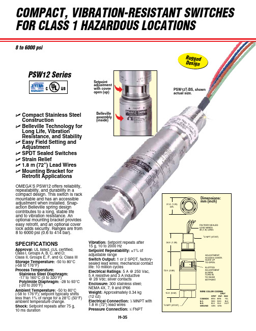
8 to 6000 psiSPECIFICATIONSApproval: UL listed, cUL certified; Class I, Groups A, B, C, and D;Class II, Groups E, F, and G; Class III Storage Temperature: -50 to 80°C (-58 to 176°F)Process Temperature:Stainless Steel Diaphragm: -17 to 160°C (0 to 320°F)Polyimide Diaphragm: -28 to 93°C (-20 to 200°F)Ambient Temperature: -50 to 80°C (-58 to 176°F); setpoint typically shifts less than 1% of range for a 28°C (50°F) ambient temperature change.Shock: Setpoint repeats after 75 g, 10 ms durationVibration: Setpoint repeats after 15 g, 10 to 2000 HzSetpoint Repeatability: ±1% of adjustable rangeSwitch Output: 1 or 2 SPDT, factory-sealed lead wires; mechanical contact life: 10 million cyclesElectrical Ratings : 5 A @ 250 Vac, 5 A resistive and 3 A inductive @ 28 Vdc; silver contactsEnclosure: 300 stainless steel; NEMA 4X, 7, 9 and IP66Weight: Approximately 0.34 kg (12 oz)Electrical Connection: 1⁄2 MNPT with 1.8 m (72") lead wiresPressure Connection: 1⁄4 FNPTB ellevilleassembly (inside)PSW12T-BS, shownactual size.compact, vibration-resistant switches for class 1 hazardous locationsr u g g e d d e s i g nSetpoint adjustment with cover open (up)psw12 seriesU Compact Stainless Steel ConstructionU Belleville Technology for Long Life, VibrationResistance, and Stability U Easy Field Setting and AdjustmentU SPDT Sealed Switches U Strain ReliefU 1.8 m (72") Lead Wires U Mounting Bracket for Retrofit ApplicationsOMEGA’S PSW12 offers reliability, repeatability, and durability in a compact design. This switch is rack mountable and has an accessible adjustment when installed. Snap-action Belleville spring design contributes to a long, stable life and to vibration resistance. Anoptional mounting bracket provides easy retrofit, and an optional cover lock adds security. Ranges are from 8 to 6000 psi (0.6 to 414 bar).PSW12T-CS, shown smaller than actual size.。
B-38BMILLIVOLT 压力传感器产品说明书

0 to 1000 0 to 68.9 PX6[*]2-1KGV D P41-S, DP25B-S, DP302-S
0 to 2000 0 to 138
PX6[*]2-2KGV D P41-S, DP25B-S, DP302-S
0 to 3000 0 to 207
PX6[*]2-3KGV D P41-S, DP25B-S, DP87
PT06F8-4S mating connector,
sold separately.
MILLIVOLT OUTPUT PRESSURE TRANSDUCERS
SQUARE
U All Stainless Steel Case
P-DPG500 Fig. 1
Actual size.
PX602-1KGV, cable style.
20.32
Pin Wire
(0.8)
A Red +Exc
B Green +Out
C Black -Out
D White -Exc
Hysteresis: ±0.2% Repeatability: ±0.05%
To Order
Stability: ±1%/year
Zero Balance: ±1%
Durability: 100 million cycles
Operating Temp: -48 to 91°C (-55 to 195°F)
Compensated Temp: -29 to 82°C (-20 to 180°F)
Thermal Zero Effect: ±0.07% full scale/°C
Thermal Span Effect: ±0.07% full scale/°C
AT9000高级传感器压力传感器进线型第二版说明书

AT9000 Advanced Transmitter Gauge Pressure TransmittersIn-line model2nd EditionNo. SS2-GTX00G-0600OVERVIEWAT9000 Advanced Transmitter is a micropro-cessor-based smart transmitter that features high performance and excellent stability. Capable of measuring gas, liquid, vapor, and liquid levels, it transmits 4 to 20 mA DC analog and digital sig-nals according to the measured pressure.It can also execute two-way communications between the Smart Communicator or HART ® 375 communicator, thus facilitating self-diagno-sis, range resetting, and automatic zero adjust-ment.FEATURESHigh performance and stability•Unique characterization and composite semi-conductor sensors realize high accuracy up to 0.04% F.S.•Our proven sensor technology enables Long-term stability up to 0.1% of URL per 10-year.Wide measuring range (range ability)•A wide measuring range is available from a single model. This feature is highly effective in taking measurement over a wide range and reducing the need for inventory.•Model GTX60G: 2.54 to 508 psig (17.5 to 3500 kPa) (range ability: 200 to 1)•Model GTX71G: 101 to 2030 psig (0.7 to 14 MPa) (range ability: 200 to 1)High durability•Max. range pressure test is cleared more than 100,000 times.•Anti-vibration specification is up to 3G .Remote communication•Two-way communication using digital output facilitates self-diagnosis, range resetting, auto-matic zero adjustment, and other operations.•HART ® protocol communication is available. (Option)China RoHSThis device is used in the Oil & Gas, Petrochem-ical, Chemical, Pulp & Paper, Food & Beverage, Machinery, Steel/Metal & Mining, and Automo-bile industries and therefore does not fall under the China RoHS Legislation.If this device is used in semiconductor manufac-turing equipment, labeling on the device and documents for the China RoHS may be required. If such documents are required, consult an Azbil Corp. representative.HART ® is a registered trademark of the HART Communication Foundation.No. SS2-GTX00G-0600Azbil Corporation- 2 -FUNCTIONAL SPECIFICATIONSFM Explosion-proof and Dust Approvals (Code F1)Explosion-proof for Class I, Division 1, Groups A, B, C and D; Class I, Zone 1, AEx d IICDust-Ignitionproof for Class II, III, Division 1, Groups E, F and GT5 -40 °C < T amb < +85 °C Hazardous locationsIndoor / Outdoor Type 4X, IP67Factory sealed, conduit seal not required for Division applicationsCaution - Use supply wires suitable for 5 °C above sur-rounding ambientFM Intrinsically safe Approval (Code F2)IS/I,II,III/1/ABCDEFG/T4; -40 °C < T amb < +60 °C; 80395278, 80395279,80395280; Entity; TYPE 4X; IP67 I/0/ AEx ia/IIC/T4; -40 °C < T amb < +60 °C; 80395278, 80395279, 80395280; Entity; TYPE 4X; IP67Entity Parameters: Vmax (Ui)=30 V olts, Imax (Ii)=100 mA, Pi=1 W, Ci=10 nF, Li=0.5 mHFM Nonincendive Approval (Code F5)NI/I/2/ABCD/T4; -40 °C < T amb < +60 °C; 80395494; NIFW; TYPE 4X; IP67NI/I/2/IIC/T4; -40 °C < T amb < +60 °C; 80395494; NIFW; TYPE 4X; IP67S/II, III/1/EFG/T4; -40 °C < T amb < +60 °C; 80395494;NIFW; TYPE 4X; P67Nonincendive Field Wiring Parameters: Vmax (Ui)=30 V olts, Ci=10 nF, Li=0.5 mHCombination of F1, F2 and F5(Code F6)ATEX Flameproof and Dust Certifications(Code A1)0344II 1/2 G Ex d IIC T6 Tprocess=85 °C-30 °C < T amb < +75 °C IP66/67II 1/2 G Ex d IIC T5 Tprocess=100 °C -30 °C < Tamb < +80 °C IP66/67II 1/2 G Ex d IIC T4 Tprocess=110 °C -30 °C < T amb< +80 °C IP66/67II 2 D Ex tD A21 IP66/67 T85 Tprocess=85 °C -30 °C < T amb < +75 °CII 2 D Ex tD A21 IP66/67 T100 Tprocess=100 °C -30 °C < T amb < +75 °CII 2 D Ex tD A21 IP66/67 T110 Tprocess=110 °C -30 °C < T amb < +75 °CCaution - Use supply wires suitable for 5 °C above sur-rounding ambientATEX Intrinsic safety and Dust Certifications (Code A2)0344II 1 G Ex ia IIC T4 TPROCESS = 105 °C-30 °C < T amb < +60 °C IP66 / 67ELECTRICAL PARAMETERS: Ui = 30 V , Ii = 93 mA, Pi = 1 W, Ci = 5 nF, Li = 0.5 mHII 1 D Ex iaD 20 IP66 / 67 T105 TPROCESS = 105 °C -30 °C < T amb < +60 °CATEX Type n and Dust Certifications (Code A5)0344II 3 G Ex nL IIC T4 TPROCESS = 105 °C -30 °C < T amb < +60 °C IP66 / 67ELECTRICAL PARAMETERS: Ui = 30 V , Ci = 5 nF, Li = 0.5 mHII 2 D Ex tD A21 IP66 / 67 T85 TPROCESS = 85 °C -30 °C < T amb < +75 °CII 2 D Ex tD A21 IP66 / 67 T100 TPROCESS = 100 °C -30 °C < T amb < +80 °CII 2 D Ex tD A21 IP66 / 67 T110 TPROCESS = 110 °C -30 °C < T amb < +80 °CNEPSI Flameproof and Dust Certifications (Code N1)Ex d IIC T6 DIP A21 T A 85 °C Tprocess=80 °C -40 °C < T amb < +75 °CEx d IIC T5 DIP A21 T A 100 °C Tprocess=95 °C -40 °C < T amb < +80 °CEx d IIC T4 DIP A21 T A 115 °C Tprocess=110 °C -40 °C < T amb < +80 °CENCLOSURE TYPE IP66/67NEPSI Intrinsic Safety Certification (Code N2)Ex ia IIC T4 Tprocess=105 °C -40 °C < T amb < +60 °C Enclosure IP66 / 67Electrical Parameters: Ui=30 V , Ii=100 mA, Pi=1 W, Ci=13 nF, Li=0.5 mHNEPSI Type n Certification (Code N5)Ex nL IIC T4 Tprocess=110 °C -40 °C < T amb < +60 °C Enclosure IP66 / 67Electrical Parameters: Ui=30 V , Ii=100 mA, Pi=1 W, Ci=13 nF, Li=0.5 mHIECEx Flameproof and Dust Certifications (Code E1)Certificate No. IECEx KEM 08.0001Ga/Gb Ex d IIC T6 Tprocess=85 °C -30 °C < T amb < +75 °C IP66/67Ga/Gb Ex d IIC T5 Tprocess=100 °C -30 °C < T amb < +80 °C IP66/67Ga/Gb Ex d IIC T4 Tprocess=110 °C -30 °C < T amb < +80 °C IP66/67Ex tD A21 IP66/67 T85 Tprocess=85 °C -30 °C < T amb < +75 °CEx tD A21 IP66/67 T100 Tprocess=100 °C -30 °C < T amb < +75 °CEx tD A21 IP66/67 T110 Tprocess=110 °C -30 °C < T amb < +75 °CCaution - Use supply wires suitable for 5 °C above sur-rounding ambientAzbil CorporationNo. SS2-GTX00G-0600- 3 -IECEx Intrinsic safety and Dust Certifications (Code E2)IECEx KEM 07.0058XZone 0 Ex ia IIC T4 TPROCESS = 105 °C -30 °C < T amb < +60 °C IP66 / 67ELECTRICAL PARAMETERS: Ui = 30 V , Ii = 93 mA, Pi = 1 W, Ci = 5 nF, Li = 0.5 mHEx iaD 20 IP66 / 67 T105 TPROCESS = 105 °C -30 °C < T amb < +60 °CIECEx Type n and Dust Certifications(Code E5)IECEx KEM 07.0058XEx nL IIC T4 TPROCESS = 105 °C -30 °C < T amb < +60 °C IP66 / 67ELECTRICAL PARAMETERS: Ui = 30 V , Ci = 5 nF, Li = 0.5 mHEx tD A21 IP66 / 67 T85 TPROCESS = 85 °C -30 °C < T amb < +75 °CEx tD A21 IP66 / 67 T100 TPROCESS = 100 °C -30 °C < T amb < +80 °CEx tD A21 IP66 / 67 T110 TPROCESS = 110 °C -30 °C < T amb < +80 °CKOSHA Flameproof (Code K1)Ex d II C T6 Tprocess = 85 °C -30 °C < T amb < +75 °CEx d II C T5 Tprocess = 100 °C -30 °C < T amb < +80 °C Ex d II C T4 Tprocess = 110 °C -30 °C < T amb < +80 °CEMC Conformity89/336/EEC, 92/31/EEC, 93/68/EEC Electromagnetic Compatibility (EMC) DirectiveMeasuring span / Setting range / Workingpressure rangeFigure 1Working pressure and temperature of wetted parts section (for general pur-pose models)Figure 2Working pressure and temperature ofwetted parts section (for oxygen and chlorine service)Supply voltage and load resistance17.9 to 42 V DC. Reverse polarity protection is standard. A load resistance of 250 : or more is necessary between loops. See Figure 3.Figure 3Supply voltage vs. load resistancecharacteristicsNote)For communication with HART communicator or Comm-Pad, a load resistance of 250 : or more is necessary.OutputAnalog output (4 to 20 mA DC) with DE protocol Analog output (4 to 20 mA DC) with HART protocol Digital output (DE protocol)Mo del Measuring Span Measuring range Overload Resistance valueGTX 60G 2.54 to 508 psi(17.5 to 3500 kPa)-14.5 to 508 psi(-100 to 3500 kPa)761 psi(5250 kPa)GTX 71G101 to 2030 psi(0.7 to 14 MPa)-14.5 to 2030 psi(-0.1 to 14 MPa)3045 psi(21 MPa)No. SS2-GTX00G-0600Azbil Corporation- 4 -Output signal3.6 to 21.6 mA3.8 to 20.5 mA (NAMUR NE43 compliant)Failure AlarmUpper: 21.6 mA or more Lower: 3.6 mA or lessAmbient temperature limitNormal operating range-31 to 158 °F (-25 to 70 °C) for general purpose models 14 to 158 °F (-10 to 70 °C) for oxygen and chlorine modelsOperative limits-40 to 185 °F (-40 to 85 °C) for general purpose models -40 to 176 °F (-40 to 80 °C) for oxygen and chlorine models-22 to 185 °F (-30 to 85 °C) for models with digital indi-catorsTransportation and storage conditions -40 to 158 °F (-40 to 70 °C)Temperature ranges of wetted partsNormal operating range-13 to 158 °F (-25 to 70 °C) for general purpose models 14 to 158 °F (-10 to 70 °C) for oxygen and chlorine modelsOperative limits-40 to 185 °F (-40 to 85 °C) for general purpose models -40 to 176 °F (-40 to 80 °C) for oxygen and chlorine modelsAmbient humidity limits5 to 100% RHStability against supply voltage change± 0.005% FS/VResponse timeBelow 100 msec. (when damping time is set to 0 sec.)Damping timeSelectable from 0 to 32 sec. in ten stagesAdjustable from 0 to 120 sec. (HART communication model)Zero Stability± 0.1% of URL per 10 year (model GTX60G)Lightning protectionApplicable Standards; IEC 61000-4-5Peak value of current surge (80/20 P sec. : 6000 AVibration effectPaint code X, H and DLess than ±0.1% of URL, field or pipeline with high vibra-tion level (10–60 Hz, 0–21 mm peak displacement/ 60–2000 Hz, 3g)Paint code ELess than ±0.1% of URL, field with general application or pipeline with low vibration level (10–60 Hz, 0–15 mm peak displacement/ 60–500 Hz, 2g)IndicatorThe digital LCD indicator (optional) indicates engineering units and can be set freely between -99999 and 99999 (5 digits). For meter calibration, specify the following items when placing your order •Meter calibration range •Meter calibration unit•Linear / Square-root for meter indication.Various kinds of data can be set using the Smart Com-municator or the HART ® 375 communicator.PaintStandardCorrosion-resistant paint (Baked acrylic paint)Corrosion-proof finishCorrosion-proof paint (Baked urethane paint), fungus-proof finishOPTIONAL SPECIFICATIONS Oil free finishThe transmitter is shipped with oil-free wetted parts.External zero/span adjustment functionThe transmitter can be easily zero/span adjusted in the field.ElbowThis is an adaptor for changing the electrical conduit con-nection port from the horizontal to the vertical direction, if required by wiring conditions in the field. One or two elbows may be used as needed.Conformance to Non SI unitsWe deliver transmitters set to any Non SI units as specified.Safety TransmitterSelect this option to be used as a component of Safety Instrumented System (SIS).AT9000 is complied with IEC 61508, certified according to Safety Integrity Level2 (SIL-2)Alarm Output (contact output)Contact output is prepared as alarm output when alarm (Output Alarm/Sensor Temp. Alarm) condition is detected. It can be set to Normally Open. (When alarm is detected, Contact ON).Custom calibrationCalibrate for the specified pressure range at the factory.Azbil CorporationNo. SS2-GTX00G-0600- 5 -PHYSICAL SPECIFICATIONS MaterialsFill fluidSilicone oil for general purpose models Fluorine oil for oxygen and chlorine models Center body 316 SSTTransmitter caseAluminum alloy, CF8M (Equivalent to 316 SST)For Wetted parts316 SST (Diaphragm 316L SST)WeightApprox. 1.3 kgINSTALLATIONElectrical connection1/2NPT internal thread, M20 internal thread.GroundingResistance 100 : max.MountingCan be installed on a 2-inch horizontal or vertical pipe (can be directly mounted on a process pipe)Process connectionMale: 1/2NPT, R1/2, G1/2, M20 × 1.5Female: 1/2NPT, Rc1/2TRANSMITTER HANDLING NOTESTo get the most from the performance this transmitter can offer, please use it properly noting the points mentioned below. Before using it, please read the Instruction Manual.Transmitter installation notesWiring notesHandling precautions for HART specifi-cation devices•If you need to operate with a secondary host (HART com-municator, etc.), set the communication interval of the pri-mary host (DCS, device management system) to 8 seconds or more, or suspend communication from the primary host. If the primary host repeats HART communication within 8 seconds, the request from the secondary host may not be received (communication may not be possible).•If electrical noise in the environment prevents HART-communications with the host, take countermeasures such as separating the signal cables from the source of the noise, improving the grounding, changing to shielded signal cables, etc. Even if noise interferes with HART communications, the 4–20 mA analog signal will be unaffected and can be used for control.•If this product is being operated in multidrop mode, there is a limit to the number of devices that can be used. If you are using multidrop mode, please consult with us.•When installing the transmitter, ensure that gaskets do not protrude from connecting points into the process (such as adapter flange connection points and connecting pipes and flanges). Failure to do so may cause a leak of process fluid,resulting in harm from burns, etc. In addition, if the process fluid contains toxic substances, take safety measures such as wearing goggles and a mask to prevent contact with the skin and eyes and to prevent inhalation.•Use the transmitter within the operating ranges stated in the specifications (for explosion-proofing, pressure rating, temperature, humidity, voltage, vibration, shock, mounting direction, atmosphere, etc.). Using the transmitter outside the operating conditions may cause device failure or fire, resulting in a harmful physical risk of burning or the like.•When performing wiring work in explosion-proof areas, follow the work method specified in the explosion-proof guidelines.•After installation, do not use the transmitter as a foothold or put your weight on it. Doing so may cause damage.•Be careful not to hit the glass indicator with tools etc. This could break the glass and cause injury.•The transmitter is heavy. Wear safety shoes and take care when installing it.•Impact to transmitter can damage sensor module .•To avoid shocks, do not perform electrical wiring work with wet hands or with live wires.•Do wiring work properly in conformance with the specifications. Wiring mistakes may result inmalfunction or irreparable damage to the instrument .•Use a power supply that conforms to the specifications. Use of an improper power supply may result in malfunction or irreparable damage to the instrument.•Use a power supply with overcurrent protection for this instrument.No. SS2-GTX00G-0600Azbil Corporation- 6 -PERFORMANCE SPECIFICATIONS Reference accuracyShown for each item are the percentage ratio for F (psi), which is the greatest value of either the upper range value (URV)*1, the lower range value (LRV)*2 or the span.Model GTX60G (for regular type)(Material of wetted parts: Diaphragm; 316L SST, Others; 316 SST)Model GTX60G (for oxygen)(Material of wetted parts: Diaphragm; 316L SST, Others; 316 SST)Model GTX71G (for regular type / oxygen)(Material of wetted parts: Diaphragm; 316L SST, Others; 316 SST)Note)*1) URV denotes the process value for 100% (20 mA DC) output.*2) LRV denotes the process value for 0% (4 mA DC) output.*3) Within a range of URV > 0 and LRV > 0.*4) Reference accuracy at calibrated condition.*5) In case code D “Digital output (DE communication)” is selected, reference accuracy becomes the same as one of “for oxygen /chlorine service”.Reference accuracy (*3)(*4)(*5)± 0.04% (For F > 50.8 psi (350 kPa))%(For F < 50.8 psi (350 kPa))Ambient Temperature effect (Shift from the set range)Change of 86°F (30°C) (*3)Combined shift:(including zero and span shifts)± 0.15%(For F > 50.8 psi (350 kPa))%(For F < 50.8 psi (350 kPa) )Reference accuracy (*3)(*4)± 0.075% (For F > 254 psi (1750 kPa))± 0.1%(254 psi (1750 kPa) > F > 20.3 psi (140 kPa) )%(For F < 20.3 psi (140 kPa))Temperature charac-teristics (Shift from the set range)Change of 86°F (30°C) (*3)(Range from 23 to 131ºF (-5 to 55ºC))Combined shift:(including zero and span shifts)± 0.44%(For F > 50.8 psi (350 kPa))%(For F < 50.8 psi (350 kPa))Reference accuracy (*3)(*4)± 0.15%(For F > 304 psi (2.1 MPa))%(For F < 304 psi (2.1 MPa))Ambient Temperatureeffect(Shift from the set range)Change of 30°C (*3)Combined shift:(including zero and span shifts)± 0.41%(For F > 508 psi (3.5 MPa))%(For F < 508 psi (3.5 MPa))0.0080.03250.8F ---------u +©¹§·r 0.0750.07550.8F ---------u +©¹§·r 0.0250.07520.3F ---------u +©¹§·r 0.190.2550.8F ---------u +©¹§·r 0.050.1+304F --------u ©¹§·r 0.180.23508F --------u +©¹§·rAzbil CorporationNo. SS2-GTX00G-0600- 7 -MODEL SELECTIONModel GTX60G(Standard gauge pressure, In-line model)Model No.:GTX__G-Selection I (I II III IV V VI VII)-Selection II (I II III IV V VI) - OptionNote)*1Not applicable for the combination with code F1 and F6 of Explosion-proof.*2Not applicable for the combination with code Q1 “Safety Transmitter” of Option.*3Not applicable for combination with code E of paint.Basic Model No.Measuring span2.54 to 508 psig (17.5 to 3500 kPa)GTX60GSelection I I Output4 to 20mA (SFN Communication)A 4 to 20mA (HART Communication)B 4 to 20 mA (SFN/HART Biringual Communication) *2E II Fill fluidRegular type (Silicone oil)A For oxygen service (Fluorine oil)H III Material (Meter-body cover, Vent/Drain plugs)Meterbody cover Vent / Drain plugs None (Direct mount)None (Direct mount)XIV Material (centerbody)316 SST (Diaphragm:316L SST)AV Process connections Rc 1/2 internal thread11/2NPT internal thread 21/2NPT external thread 3R1/2 external thread 4G1/2 external thread5M20 × 1.5 external thread7VI Process installation Direct mounting FVII Bolt/nut NoneXSelection II-I Electrical connection 1/2 NPT, Watertight A M20, Watertight *1B IIExplosion-proofNoneXX FM Explosion-proof F1FM Intrinsically safe F2FM NonincendiveF5Combined of FM Explosion-proof, Intrinsically safe and Nonincendive F6ATEX Explosion-proof A1ATEX Intrinsically safe A2ATEX Type nA5IECEx Explosion-proof E1IECEx Intrinsically safe E2IECEx Type nE5NEPSI Explosion-proof *3N1NEPSI Intrinsically safe *3N2NEPSI Type n *3N5KOSHA Explosion-proof *3K1Taiwan Explosion-proof T1III Indicator NoneX With indicator AIV Paint *13StandardX None (316 stainless steel housing) *This option will be available in the future.E Corrosion-proof (Urethane)HV Failure alarmUP Scale A DOWN scale BVI Mounting bracket NoneX CF8 (L form)1No. SS2-GTX00G-0600Azbil Corporation- 8 -Model GTX71G (High gauge pressure In-line model)Model No.:GTX_ _G - Selection I (I II III IV V VI VII) - Selection II (I II III IV V VI) - OptionNote)*1Not applicable for the combination with code F1 and F6 of Explosion-proof.*2Not applicable for the combination with code Q1 “Safety Transmitter” of Option.*3Not applicable for combination with code E of paint.Basic Model No.Measuring span 101 to 2030 psig (0.7 to 14 MPa)GTX71GSelection I I Output4 to 20 mA (SFN Communication)A 4 to 20 mA (HART Communication)B 4 to 20 mA (SFN/HART Biringual Communication) *2E II Fill fluidRegular type (Silicone oil)A For oxygen service (Fluorine oil)H III Material (Meter-body cover, Vent/Drain plugs)Meterbody cover Vent / Drain plugs None (Direct mount)None (Direct mount)XIV Material (centerbody)316 SST (Diaphragm: 316L SST)AVProcess connections Rc 1/2 internal thread11/2NPT internal thread 21/2NPT external thread 3R1/2 external thread 4G1/2 external thread5M20 × 1.5 external thread7VI Process installation Direct mounting FVII Bolt/nut NoneXSelection II-I Electrical connection 1/2 NPT, Watertight A M20, Watertight *1B IIExplosion-proofNoneXX FM Explosion-proof F1FM Intrinsically safe F2FM NonincendiveF5Combined of FM Explosion-proof, Intrinsically safe and Nonincendive F6ATEX Explosion-proof A1ATEX Intrinsically safe A2ATEX Type nA5IECEx Explosion-proof E1IECEx Intrinsically safe E2IECEx Type nE5NEPSI Explosion-proof *3N1NEPSI Intrinsically safe *3N2NEPSI Type n *3N5KOSHA Exposion-proof *3K1Taiwan Explosion-proof T1III Indicator NoneX With indicator AIV Paint *12StandardX None (316 stainless steel housing) *This option will be available in the future.E Corrosion-proof (Urethane)HV Failure alarmUP scale A DOWN scale BVI Mounting bracket NoneX CF8 (L form)1Azbil Corporation No. SS2-GTX00G-0600- 9 -Model No.:GTX_ _G -Selection I ( I II III IV V VI VII) - Selection II (I II III IV V VI ) - OptionNote)*1No need to select when Fill Fluid code H, or J is selected.*2Not applicable for the combination with code A2, or Q7 of Option*3Not applicable for the combination with code A, or B of Process installation.*4Not applicable for the combination with code F1, F6 of Explosion-proof.*5Not applicable for any Explosion-proof. Please select code XX “None” of Explosion-proof.*6Not applicable for the combination with code B “M20 watertight” of Electrical connection.*7Not applicable for the combination with code X “None” of Indicator. Please select “With indicator”.*8Not applicable for the combination with code D “Digital output(DE communication)” of output*9Not applicable for the combination with code F2, F5, F6, N2, N5, E2, E5, A2 and A5 of Explosion-proof.*10In case code P8 is selected, code E of Paint should be selected.*11In case code P8 is selected, code X of Mounting bracket shoult be selected.Option-No optionsXX With external Zero/Span adjustment *7*8A2One elbow (left) *3*4*6G1One elbow (right) *3*4*6G22 elbows *3*5*6G3Oil and water free finish K1Oil free finish *1K3316 SST (Parts in contact with atmosphere) *10*11P8Safety Transmitter *2*8Q1NAMUR NE43 Compliant Output signal limits:3.8 to 20.5 mA (Output 21.6 mA/selected upper limit, 3.6 mA/selected lower limit) *8Q2Alarm Output (contact output) *9Q7Custom calibration R1Test report T1Mill certificateT2Traceability certificate T4Non SI UnitW1No. SS2-GTX00G-0600Azbil Corporation DIMENSIONS- 10 -Azbil Corporation No. SS2-GTX00G-0600- 11 -。
Parker Hannifin MPS-2压力传感器说明书

MPS-2 VersatileFeaturesMPS-R2M5-NGRMPS-2Features• Pressure Ranges: Vacuum Pressure ..................0 to -30 inHg Compound Pressure .......-14.7 to 72.5 PSI • Sensor Outputs:2 NPN or PNP Open Collector Transistor Output , 30VDC, 125mA• Hysteresis or Window Comparator Mode • 4 Selectable Units of Measure (mmHg, -bar, -kPa, inHg) (kgf/cm 2, PSI, bar, kPa)• Output Response Time Less Than 2.0 Milliseconds • CE Marked• Air and Non-Corrosive Gases • Error MessageMPS-2 Programming OptionsOutputs Change N.O. / N.C.4Units of Measure change 4EZY Mode 4Hysteresis Mode4Window Comparator Mode4Auto Teach Mode 4Auto Surveillance Mode 4Display Refresh Settings 4Output Response Time4Display Peak / Bottom Difference Value 4Special Display Features 4Lockout Option 4Peak Value at a Touch 4Bottom Value at a Touch 4Zero Reset4Red / Green LED Display Options Peak Surveillance Mode Energy Savings Mode 4Scan Mode Password Lockout Error Output Mode Setting of Decimal PointMPS-V2N-PCOrdering Information, SpecificationsMPS-2 VersatileSpecificationsPressure RangeVacuum (V)Compound (R)Units of Measure Display Resolution bar:0.001bar:0.01kPa: 0.1kPa:1mmHg: 1kgf/cm 2: 0.01inHg:0.1PSI:0.1MediaAir and Non-Corrosive GasesPressure Port (N) 1/8" NPT, (M5) M5 Female (Consult Factory for BSPP or BSPT Port)Proof Pressure(V) 72.5 PSI, (R) 116.0 PSI Operating Temperature 32 to 122°F (0 to 50°C)Storage Temperature14 to 140°F (-10 to 60°C)Humidity35 to 85% RHElectrical Connection(C) 4-Pin, M8 Connector, (G) 2m Grommet Open LeadPower Supply10.8 to 30VDC, Ripple Vp-p 10% Max., Reverse Voltage Protection Display3-Digit, 7-Segment LEDDisplay Refresh 0.1 to 3.0 sec. (Factory set at 0.1)Output Circuit NPN (Sinking) or PNP (Sourcing) Output, Open Collector T ransistor 30VDC, 125mA Switch Output 2 Output Signals, NPN or PNP , Normally Open or Closed, LED Indicator Output Modes Hysteresis or Window ComparatorResponse Time < 2ms, with Programmable Increments 32, 128, 1024ms Repeatability ± 0.2% F .S.Thermal Error 1% over ±25°C (77°C) Temperature Change: Range 32 to 122°F (0 to 50°C)General Protection IP65 or IP40, CE Marked, EMC-EN55011 Class B, EN 50082-2Insulation Resistance > 100M ohms at 500VDC Vibration Resistance 10 to 55Hz, 1.5mm, XYZ, 2 hrs.Shock Resistance10 G, XYZMaterial Housing: Polycarbonate, Pressure Port: Zinc Die-cast Mass1.58 oz. (45g)MPS-2 Ordering NumbersPressure RangePort Size Output CircuitElectrical ConnectorPart Number 0 to -30 inHg1/8 NPT*, Male, M5 FemalePNP Sourcing 4 Pin, M8MPS-V2N-PC NPN Sinking MPS-V2N-NC -14.7 to 72.5 PSIPNP Sourcing 4 Pin, M8MPS-R2N-PC NPN SinkingMPS-R2N-NC M5 DIN Rail MountingPNP Sourcing 2M Lead WireMPS-R2M5-PGR NPN SinkingMPS-R2M5-NGR* BSPP(G) and BSPT(R) are available. Replace N with G or R for port thread type Example : MPS-V2N-PC (NPT) , MPS-V2G-PC (BSPP) or MPS-v2R-PC (BSPT)MPS-2 VersatileTechnical Information!NPN Sinking PNP SourcingInternal Circuit–INCLUDED–Cautions The MPS-2 Pressure Sensor is designed to monitor pressure and is not a safety measure to prevent accidents.The compatibility of the sensor is the responsibility of the designer of the system and specifications.Operating Environment• Parker / Convum Sensors have not been investigated for explosion-proof construction in hazardous environments.• Do not use with flammable gases, liquids, or in hazardous environments.• Avoid installing the sensor in locations where excessive voltage surges could damage or affect the performance of the sensor.Operations• Dedicate a power supply of 10.8 to 30VDC to the sensor and set the ripple to Vp-p10% or less. Avoid excessive voltage. Avoid voltage surges.• A small amount of internal voltage drop is possible. Ensure the power supply minus any internal voltage drop exceeds the operating load.• Verify the operating media is compatible with thespecified sensor. Check the chemical make-up, operating temperatures, and maximum pressure ranges of the system before installing.• Installation of air dryer system is recommended to remove moisture.Installation• Never insert an object into the pressure port other than an appropriate fluid connector.• Avoid short-circuiting the sensor. Connect the brown lead to V+ and blue lead to 0V .• Do not connect the output lead wires (black / white) to the power supply.• Outputs not being used should be trimmed and insulated.• Install as shown using the metal mounting base.• To achieve IP65 rating, connect the o-ring and barb as shown to a normal environment with a 2mm I. D. tube.2143P in #1 Brown: 24VDC2 White: NPN / PNP Open Collector Output 23 Blue: 0VDC4 Black: NPN / PNP Open Collector Output 1Sensor Pin OutLead WiringBrown V+White NPN / PNP Output 2Blue 0VBlackNPN / PNP Output 1Error MessagesDisplay DescriptionSolutionsErr Zero Reset Error Reset Zero Below 3% of F .S. Er1System Error (Internal)Contact Factory Er2Auto Teach Mode Error Restart Function CE1Over current of Output 1Load current exceeds maximum 125mA. CE2Over current of Output 2FFF –FFApplied pressure exceeds pressure rangeApply pressures within the rating of the sensorDimensionsMPS-2 VersatileDimensionsProgramming Features MPS-2 Versatile See last page of this PDF for Symbol Explanation.AccessoriesMPS-2 VersatileMPS-ACCK4Din RailAccessoriesCablesProgramming Symbols Legend Technical DataPressure Value Display Mode. Displays Pressure for a specific time period and then updates for next time periodTime Range for Pressure Value Display Mode Value Setting for Pressure Value Display Mode Display Peak Value over selected time range Display Bottom Value over selected time range Display Difference over selected time range Display Function Mode. On/OffDisplay Function. Selects display types.Display blinks pressure when Output 1 is Passing Normal when Output 1 is Non-PassingDisplay blinks pressure when Output 2 is Passing Normal when Output 2 is Non-PassingDisplay shows pressure when Output 1 is Passing Display shows special screen when Non-Passing Display shows pressure when Output 2 is Passing Display shows special screen when Non-Passing Select Switch Output setting for MPS-31Color Setting for MPS-31MPS-4, Port Reference SelectionMPS-4, Display change of B port to A port static MPS-4, Display change of A port to B port staticMPS-4, Display change of A port tochange of B portMPS-7, Pressure Range Selection Vacuum MPS-7, Pressure Range Selection Low PressureMPS-7, Pressure Range SelectionPositive PressureMPS-7, Pressure Range Selection Compound PressureMPS-7, Energy Savings Mode, reduces current consumptionMPS-7, Peak SurveillanceDigital Input Sensors Only. Digital Input Mode for remote Zero reset of sensorsDigital InputDigital ChannelMPS-7 Scan Mode. Sensor scans and displays each channel for 3 sec.Locked. Sensor programs cannot be changed Unlocked. Sensor programs can be changedSets Sensors reference point to current atmospheric conditions。
压力传感器操作指南说明书

压力传感器操作指南说明书操作指南说明书1. 产品概述本操作指南说明书旨在向用户介绍压力传感器的正确操作方法。
压力传感器是一种用于测量物体压力或压力变化的设备,广泛应用于工业领域中的自动化控制系统中。
本说明书将详细介绍压力传感器的各个部件、规格参数以及正确的使用方法。
2. 产品组成压力传感器主要由以下部件组成:- 压力感应器头:用于感知物体的压力,并将其转换为电信号。
- 电路板:将压力感应器头的信号转换为数字信号,通过接口与控制系统进行通信。
- 接口:用于与外部设备连接,传输数字信号。
3. 使用前准备在开始使用压力传感器之前,请确保以下步骤已完成:- 检查传感器的外观是否完好,如有损坏请勿使用。
- 查看产品标识,确认传感器是否适用于您的应用场景。
- 连接传感器到合适的电源,并确保电源电压符合规定。
4. 使用步骤4.1 连接传感器将传感器的接口与控制系统的接口连接,确保连接稳固且无松动。
4.2 设定工作参数根据实际需求,通过控制系统设置传感器的工作参数,如测量范围、刷新频率等。
4.3 校准传感器首次使用传感器或者在长时间使用后,应进行校准操作,以确保精准测量。
具体校准方法请参考附带的校准指南。
4.4 启动传感器通电后,传感器会自动进行初始化,并开始测量工作。
在使用过程中,传感器会持续监测压力变化,并将测量结果通过控制系统进行处理和显示。
4.5 关闭传感器在不使用传感器时,应及时关闭电源,避免长时间不必要的功耗。
5. 注意事项- 请勿在高温、潮湿、腐蚀性环境中使用传感器,以免影响性能和寿命。
- 请勿将压力传感器投掷、撞击或受到过大的力量挤压,以免损坏设备。
- 若传感器长时间不使用,请妥善保管,并放置在干燥、清洁的环境中。
6. 故障排除一旦发现传感器工作异常或显示数值不准确,应立即停止使用,并进行以下检查:- 检查设备连接是否松动或损坏。
- 检查控制系统设置是否正确。
- 尝试重新校准传感器。
若问题仍未解决,请联系售后服务中心或厂家进行进一步的维修和处理。
ISE70 ISE71 压力传感器用户指南说明书

5 Pressure SettingDefault settingsWhen the pressure exceeds the set value, the switch will be turned on.When the pressure falls below the set value by the amount of hysteresis or more, the switch will be turned off.The default setting is to turn on the pressure switch when the pressure reaches the center of the atmospheric pressure and upper limit of the rated pressure range. If this condition is acceptable, then keep thesesettings.UP button When tightening, do not hold the ISE70/ISE71 body with a spanner.How to use connectorAlign the cable connector key groove with the product connector key to insert and rotate the knurled part of the connector.Connect the wires of the lead wire with M12 connector as shown below.M12 connector (Port Class A)4132Power is suppliedPress the SET button once.Press the SET button between 1and 3 sec.∗: The outputs will continue to operate during setting.∗: If a button operation is not performed for 30 sec. during the setting, the display will flash.(This is to prevent the setting from remaining incomplete if, for instance, an operator were to leave during setting.)∗: 3 step setting mode, simple setting mode and function selection mode settings are reflected each other.Switch ON At normal outputSwitch OFFSet value P_1Hysteresis H_1TimeP r e s s u r e•The upper part (display) of the product can be rotated by 336°.Rotating the display with excessive force will damage the end stopper.Press the SET button between 3and 5 sec.2 Summary of Product partsNames of individual partsPipingPiping specification: -02 and -N02After hand tightening, tighten the fitting using a spanner on the flat surfaces of the fitting.The tightening torque must be 8 to 12 Nm.Piping specification: -F02After hand tightening, tighten the fitting using a spanner on the flat surfaces of the fitting.The tightening torque must be 4 to 5 Nm.336° rotationWiringConnections should be made with the power supply turned e a separate route for the product wiring and any power or high voltage wiring.Otherwise, malfunction may result due to noise.If a commercially available switching power supply is used, be sure to ground the frame ground (FG) terminal. If the switching power supply is connected, switching noise will be superimposed and it will not be able to meet the product specifications.In that case, insert a noise filter such as a line noise filter/ferrite between the switching power supplies or change the switching power supply to the series power supply.Installation & Maintenance ManualHigh-precision Digital Pressure Switch ISE70/ISE71This manual contains essential information for the protection of users and others from possible injury and/or equipment damage.•Read this manual before using the product, to ensure correct handling,and read the manuals of related apparatus before use.•Keep this manual in a safe place for future reference.•These instructions indicate the level of potential hazard by label of "Caution", "Warning" or "Danger", followed by important safety information which must be carefully followed.•To ensure safety of personnel and equipment the safety instructions in this manual and the product catalogue must be observed, along with other relevant safety practices.This product is class A equipment that is intended for use in an industrial environment.There may be potential difficulties in ensuring electromagneticcompatibility in other environments due to conducted as well as radiated disturbances.WarningDo not disassemble, modify (including changing the printed circuit board) or repair.An injury or failure can result.Do not operate the product outside of the specifications.Do not use for flammable or harmful fluids.Fire, malfunction, or damage to the product can result.Verify the specifications before use.Do not operate in an atmosphere containing flammable or explosive gases.Fire or an explosion can result.This product is not designed to be explosion proof.Do not use the product in a place where static electricity is a problem.Otherwise it can cause failure or malfunction of the system.If using the product in an interlocking circuit:•Provide a double interlocking system, for example a mechanical system•Check the product regularly for proper operation Otherwise malfunction can result, causing an accident.The following instructions must be followed during maintenance:•Turn off the power supply•Stop the air supply, exhaust the residual pressure and verify that the air is released before performing maintenance work Otherwise an injury can result.CautionDo not touch the terminals and connectors while the power is on.Otherwise electric shock, malfunction or damage to the product can result.After maintenance is complete, perform appropriate functional inspections and leak tests.Stop operation if the equipment does not function properly or there is a leakage of fluid.When leakage occurs from parts other than the piping, the product might be faulty.Disconnect the power supply and stop the fluid supply.Do not apply fluid under leaking conditions.Safety cannot be assured in the case of unexpected malfunction.Refer to the operation manual on the SMC website(URL ) for more information about safety instructions.URL (Global) (Europe)Specifications are subject to change without prior notice from the manufacturer.© 2017 SMC Corporation All Rights Reserved13 ContactsAUSTRIA (43) 2262 62280-0NETHERLANDS (31) 20 531 8888 BELGIUM (32) 3 355 1464 NORWAY (47) 67 12 90 20 CZECH REP.(420) 541 424 611 POLAND (48) 22 211 9600 DENMARK (45) 7025 2900 PORTUGAL (351) 21 471 1880FINLAND (358) 207 513513 SLOVAKIA (421) 2 444 56725 FRANCE (33) 1 6476 1000 SLOVENIA (386) 73 885 412GERMANY (49) 6103 4020 SPAIN (34) 945 184 100 GREECE (30) 210 271 7265 SWEDEN(46) 8 603 1200 HUNGARY (36) 23 511 390 SWITZERLAND (41) 52 396 3131 IRELAND (353) 1 403 9000 UNITED KINGDOM(44) 1908 563888ITALY(39) 02 92711BULGARIA (359) 2 974 4492ESTONIA (372) 651 0370 ROMANIA (40) 21 320 5111LATVIA (371) 781 77 00 LITHUANIA(370) 5 264 8126 Default settingThe default setting is as follows.If no problem is caused by this setting, keep these settings.●[F 0] Display units, switch output specifications and diagnostic●Other parameter settingsPeak/bottom value indicationThe max. (min.) pressure when the power is supplied is detected and updated.The value can be displayed on the sub display by pressing the UP or DOWN button in measurement mode.Snap shot functionThe current pressure value can be stored to the switch output ON/OFF set point.When the set value and hysteresis are set, press the UP and DOWNbuttons for 1 sec. or longer simultaneously. Then, the set value of the sub display (right) shows [- - -], and the values corresponding to the current pressure values are automatically displayed.Zero-clear functionIn measurement mode, when the UP and DOWN buttons are pressed for 1 sec. or longer simultaneously, the main display shows [- - -], and then reset to zero.The display returns to measurement mode automatically.Key-lock functionTo set each of these functions, refer to the SMC website(URL ) for more detailed information, or contact SMC.10 MaintenanceHow to reset the product after a power cut or forcible de-energizing The setting of the product will be retained as it was before a power cut or de-energizing.The output condition is also basically recovered to that before a power cut or deenergizing, but may change depending on the operating environment.Therefore, check the safety of the whole installation before operating the product. If the installation is using accurate control, wait until the product has warmed up (approximately 10 to 15 minutes).11 TroubleshootingError indication functionThis function is to display error location and content when a problem or error has occurred.Function selection modeIn measurement mode, press the SET button between 3 and 5 sec., to display [F 0]. Select to display the function to be changed [F□□]. Press and hold the SET button for 2 sec. or longer in function selection mode to return to measurement mode.∗: Some products do not have all the functions. If no function is available or selected due to configuration of other functions, [- - -] is displayed on the sub display (right).(URL ) for more detailed information, or contact SMC.●[F 1] Setting of OUT1●[F 2] Setting of OUT2Same setting as [F 1] OUT1.12 Refer to the product catalog or SMC website(URL ) for more information about the product specifications and outline dimensions.other than above are displayed, please contact SMC.Refer to the SMC website (URL ) for more information about troubleshooting.[3 step setting mode (hysteresis mode)]In the 3 step setting mode, the set value (P_1 or n_1) and hysteresis (H_1) can be changed. Set the items on the sub display (set value or hysteresis) with the UP or DOWN button. When changing the set value,follow the operation below. The hysteresis setting can be changed in the same way.(1) Press the SET button once when theitem to be changed is displayed on thesub display. The set value on the sub display (right) will star flashing.(2) Press the UP or DOWN button to change the set value.The set value can be increased with the UP button and can bereduced with the DOWN button. When the UP and DOWN buttons are pressed and held simultaneously for 1 sec. or longer, the set value is displayed as [- - -], and the set value will be the same as the current pressure value automatically (snap shot function).Afterwards, it is possible to adjust the value by pressing the UP or DOWN button.(3) Press the SET button to complete the setting.The pressure switch turns on within a set pressure range (from P1L to P1H) during window comparator mode. Set P1L, the lower limit of the switch operation, and P1H, the upper limit of the switch operation and WH1 (hysteresis) following the instructions given above.(When reversed output is selected, the sub display (left) shows [n1L] and [n1H].)∗: Set OUT2 in the same way. (ex. P_2, H_2)∗: Setting of the normal/reverse output switching and hysteresis/window comparator mode switching are performed with the function selection mode [F 1] OUT1setting and [F 2] OUT2 setting.(1) Press and hold the SET button between 1 and 3 sec.in measurement mode. [SEt] is displayed on the main display.When the button is released while in the [SEt] display, the current pressure value is displayed on the main display,[P_1] or [n_1] is displayed on the sub display (left), and the set value is displayed on the sub display (right) (Flashing).(2) Change the set value with the UP or DOWN button, and press the SET button to set the value. Then, the setting moves to hysteresis setting.(The snap shot function can be used.)(3) Change the set value with the UP or DOWN button, and press the SET button to set the value. Then, the setting moves to the delay time of the switch output.(The snap shot function can be used.)(4) Press the UP or DOWN button, the delay time of the switch output can be selected.Delay time setting can prevent the output from chattering.The delay time can be set in the range 0.00 to 60.00 sec. in 0.01 sec.increments.(5) Press the SET button for less than 2 seconds to complete the OUT1setting.[P_2] or [n_2] is displayed on the sub screen (left). Continue with setting the OUT2.Press and hold the SET button for 2 seconds or longer to complete the setting.The product will return to measurement mode.In the window comparator mode, set P1L, the lower limit of the switch operation, and P1H, the upper limit of the switch operation, WH1(hysteresis) and dt1 (delay time) following the instructions given above.(When reversed output is selected, the sub display (left) shows [n1L] and [n1H].)∗: Set OUT2 in the same way.Currentvalue。
Ashcroft 压力传感器说明书
1. GENERAL:A failure resulting in injury or damage may be caused by excessive overpressure, excessive vibration or pressure pulsation, excessive instrument temperature, corro -sion of the pressure containing parts, or other misuse. Consult Ashcroft Inc., Strat -ford, Connecticut, USA before installing if there are any questions or concerns.2. OVERPRESSURE:Pressure spikes in excess of the rated overpressure capability of the transducer may cause irreversible electrical and/or mechanical damage to the pressure mea -suring and containing elements.Fluid hammer and surges can destroy any pressure transducer and must always be avoided. A pressure snubber should be installed to eliminate the damaging ham -mer effects. Fluid hammer occurs when a liquid flow is suddenly stopped, as with quick closing solenoid valves. Surges occur when flow is suddenly begun, as when a pump is turned on at full power or a valve is quickly opened.Liquid surges are particularly damag -ing to pressure transducers if the pipe is originally empty. T o avoid damaging surges, fluid lines should remain full (if possible), pumps should be brought up to power slowly, and valves opened slowly. T o avoid damage from both fluid hammer and surges, a surge chamber should be installed.Symptoms of fluid hammer and surge's damaging effects:• P ressure transducer exhibits an output at zero pressure (large zero offset). • P ressure transducer output remains constant regardless of pressure• In severe cases, there will be no output.FREEZING:Prohibit freezing of media in pressure port. Unit should be drained (mount in vertical position with electrical termination upward) to prevent possible overpressure damage from frozen media.3. STATIC ELECTRICAL CHARGES:Any electrical device may be susceptible to damage when exposed to static electri -cal charges. T o avoid damage to the trans -ducer observe the following:• O perator/installer should follow proper ESD (electrostatic discharge) protection procedures before handling the pressure transducer.Note: The shield and drain wire in the cable (if supplied) is not connected to the transducer body, and is not a suitable ground.MOUNTINGThe transducer requires no special mount i ng hardware, and can be mounted in any plane with negligible position error.Although the unit can withstand normal vibration without damage or significant output effects, it is always good practice to mount the transducer where there is mini -mum vibration.For units with NPT type pressure fittings apply teflon tape or an equivalent sealant to the threads before installing.When tightening, apply a wrench to the hex wrench flats located just above the pres -sure fitting. DO NOT tighten by u sing a pipe wrench on the housing.POWER SUPPL Y – K1 Models OnlyThe supply voltage for the 1-5 and 1-6 Vdc output transducers must be within the range of 10 to 36 Vdc. The maximum s upply volt -age for a 4-20mA current output transducer is 36 Vdc while the minimum supply voltage is dependent upon the loop resistance of the circuit. The load limitation chart shows the minimum supply voltage (V min ) required for a given loop r esistance (R LOOP ).NOISEFor minimum noise susceptibility, avoid run n ing the transducer’s cable in a con d uit that contains high current AC power cables. Where possible avoid running the cable near inductive equipment.SHIELD WIRINGConnect the braided shield to the guard terminal on the reading instrument (meter, etc.) if available or to ground or to the power supply negative terminal.WARNING! READ BEFORE INSTALLATIONm ADJUSTMENT POTENTIOMETERS The zero and span pots are accessiblethrough the top of the case. Loosen the four screws and separate the top carefully. The zero pot is marked with a white dot. VENT TUBEThe cable will have a clear T eflon vent tube that's required at pressure below 500 psi to provide atmospheric reference. The open end should be placed in a dry area.OUTPUT – K8 OnlySensitivity may be from 6 mV/V to 18 mV/V for any individual transducer. Zero offset is within ±3 mV/V . Output is proportional to supply voltage (ratiometric).EXCITATION – K8 & K2For proper operation a voltage within the range of 5 to 10 Vdc must be applied be -tween the transducer’s supply terminals.mVariationWire Hookup Red = + Power XTQ Black = Common White = Output Red = + Power XTG Black = CommonGreen=OutputK8 Transducers – Electrical ConnectionsCable Type F2Red = + Power White = – PowerGreen = + Output Black=– Output4 Inch LeadsRed* = + Power White = – Power Green = + Output Blue = – Output*Orange = + Power, RoHS compliantversions3-Wire Voltage4-20 mA4-Wire Ratiometric (mV/V)Ratiometric (mV/V)K2 Transducers – Electrical ConnectionsK1 Transducers – Electrical ConnectionsK1, K2 TransducersNOTE: All dimensions are decimal inchesDimensionsWiring Diagrams for All Transducers++––POWER SUPPLY(- Power)(+ Power)(- Output)(+ Output)METERTRANSDUCERRED WHITE GREEN BLACK ++––POWER SUPPLY(Common)(+ Power)(+ Output)METERTRANSDUCERPOWER (Blue, K8 only)。
压力传感器说明书

半导体式压力传感器的结构与动作说明应变片式压力传感器的结构与动作说明●半导体隔膜式压力传感器的结构与动作说明●特点●传感器芯片的结构半导体隔膜式压力传感器采用双重隔膜方式,由直接与测量介质接触的高耐腐蚀性金属隔膜(相当于Hastelloy哈氏合金C-22、SUS316L等)与通过封入的硅油检测压力的硅芯片(硅隔膜)构成。
通过压力导入口直接与测量介质接触的是SUS316L隔膜(或相当于Hastelloy哈氏合金C-22等),介质(空气、水、油及其他)不会浸入其中,能够稳定测量。
[连接螺丝的形状为G3/8时,与配管间采用O型圈密封(氟橡胶)。
]●可以制作能够测量正压、负压、连成压、绝对压力的各种传感器元件●直接接触介质的受压部可以采用相当于Hastelloy哈氏合金C-22、 SUS316L的材料制作,因此,耐腐蚀性能优良●用于检测压力的硅芯片,其隔膜厚度较大,因此,具有优良的耐压性能●半导体隔膜式压力传感器 VESW , VESX , VESY , VESZ , VHR3 , VHG3 , VAR3 , VAG3 , VPRNP , VPNPR , VPNPG , VNF , HS1 , HV1 , AS1 , AV1 , NS1 , NV1 , VESI , VESV , VSW2 , VST 等●应变片式压力传感器 VSD4 , NSMS-A6VB , HSSC , HSSC-A6V , VHS , VHST , HSMC2, HSMC , VPE , VPB , VPRT , VPRTF , VPRQ , VPRQF , 0VPVT , VPVTF , VPVQ , VPVQF , VPRF , VFM , VF , VTRF , VPRF2 , VPRH2 等硅芯片受压部(硅隔膜)与通常的IC制作工艺相同,利用杂质扩散原理形成硅应变片。
当向硅芯片施加压力时,电阻应变片的电阻值会随着其变形而改变,并转换为电信号。
迪迪电子 4-20mA压力传感器说明书

To Order
GAGE PRESSURE RANGES
psi
bar
MODEL NO.
0 to -14.7 0 to 1 0 to 6 0 to 15 0 to 30 0 to 60 0 to 100 0 to 150
0 to -1.0 0 to 0.0689 0 to 0.414 0 to 1.0 0 to 2.1 0 to 4.1 0 to 6.9 0 to 10.3
Total Error Band: 1% FS (includes temperature effects within compensated temperature range)
Operating Temperature: -40 to 80°C (-40 to 176°F)
Compensated Temperature: -25 to 75°C (-13 to 167°F)
0 to 200
0 to 13.8
PX182B-200GI DP24-E, DP25B-E, DP41-E, DPi Series
SPECIFICATIONS
Excitation: 11 to 30 Vdc
Output: 4 to 20 mA (2 wire)
Accuracy: 0.3% BFSL maximum (includes linearity, hysteresis and repeatability)
The PX182B is fully digitally compensated for the effects of pressure and temperature change. It is extremely accurate, with less than 0.3% FS reference accuracy and less than 1% FS over its compensated temperature range.
PX3400系列薄膜压力传感器产品说明书

B-61THIN-FILM PRESSURE TRANSDUCER FOR OIL WELL LOGGING TOOLSULTRA-HIGH LONG-TERM STABILITYPX3400 SeriesmV/V Output0-1000 to 0-20,000 psi absolute 0-70 to 0-1400 bar absolute1 bar = 14.5 psi1 kg/cm 2= 14.22 psi1 atmosphere = 14.7 psi = 29.93inHg = 760.2 mmHg = 1.014 barPX3425-0004, $1395,shown smaller thanactual size.ߜVibration Resistance ߜOutstanding Stability at High Temperatures ߜSmall 19 mm (0.75")Body Diameter ߜHigh OperatingTemperature—Up To 177°C (350°F)ߜSolid State Reliability ߜGaged Diaphragm for Accurate Data and Fast Warm-UpߜBuilt-In Temperature Sensor for Thermal CorrectionߜStainless Steel Wetted PartsߜAvailable with Inconel ®Wetted Parts for Wells with Sour Gas or for Brine-Induced WellsOMEGA’s PX3400 Series pressure transducers have earned areputation for high performance,reliability, and stability in tough, real-world applications. They are particularly useful in deep well tools,with a narrow body diameter of 19mm (0.75") and pressure ranges up to 20,000 psi (1400 bar). Two models are available: the PX3425operates at up to 121°C (250°F),and the high-temperature PX3435 operates at up to 177°C (350°F). These outstanding transducers use OMEGA’s advanced sputtered thin-film sensor technology.Thousands of them are used on oil well logging tools throughout the world.Stability in such operations is critical. A transducer that shifts during a logging cycle invalidates costly data. The PX3400 Series uses thin-film strain gages, sputter deposited on a metal diaphragm.This advanced-technology gage system provides superior stability,especially at the high temperatures often found in oil wells.The diaphragm is machined from vacuum-remelted 17-4 PH stainless steel with elaborate annealing,aging, and stress-relieving processes to ensure a stable system. Thegaged-diaphragm design minimizes the number of components and welds in the transducer, increasing the reliability and precision oflogging data. The heat-sink effect of the diaphragm and the high bridge resistance reduce gage self-heating,decrease warm-up time, andconserve battery power. A built-in platinum resistance temperature element (RTD) provides data for correcting temperature effects using an external microprocessor. OMEGA’s PX3400 Series transducer can be modified to meet your design requirements. A broad selection of optional features is available,including pressure and electrical connections, special testing,additional thermal compensation,and 200°C (400°F) operating temperatures.DISCONTINUEDDISCONTINUEDDISCONTINUEDCANADA www.omega.ca Laval(Quebec) 1-800-TC-OMEGA UNITED KINGDOM www. Manchester, England0800-488-488GERMANY www.omega.deDeckenpfronn, Germany************FRANCE www.omega.frGuyancourt, France088-466-342BENELUX www.omega.nl Amstelveen, NL 0800-099-33-44UNITED STATES 1-800-TC-OMEGA Stamford, CT.CZECH REPUBLIC www.omegaeng.cz Karviná, Czech Republic596-311-899TemperatureCalibrators, Connectors, General Test and MeasurementInstruments, Glass Bulb Thermometers, Handheld Instruments for Temperature Measurement, Ice Point References,Indicating Labels, Crayons, Cements and Lacquers, Infrared Temperature Measurement Instruments, Recorders Relative Humidity Measurement Instruments, RTD Probes, Elements and Assemblies, Temperature & Process Meters, Timers and Counters, Temperature and Process Controllers and Power Switching Devices, Thermistor Elements, Probes andAssemblies,Thermocouples Thermowells and Head and Well Assemblies, Transmitters, WirePressure, Strain and ForceDisplacement Transducers, Dynamic Measurement Force Sensors, Instrumentation for Pressure and Strain Measurements, Load Cells, Pressure Gauges, PressureReference Section, Pressure Switches, Pressure Transducers, Proximity Transducers, Regulators,Strain Gages, Torque Transducers, ValvespH and ConductivityConductivity Instrumentation, Dissolved OxygenInstrumentation, Environmental Instrumentation, pH Electrodes and Instruments, Water and Soil Analysis InstrumentationHeatersBand Heaters, Cartridge Heaters, Circulation Heaters, Comfort Heaters, Controllers, Meters and SwitchingDevices, Flexible Heaters, General Test and Measurement Instruments, Heater Hook-up Wire, Heating Cable Systems, Immersion Heaters, Process Air and Duct, Heaters, Radiant Heaters, Strip Heaters, Tubular HeatersFlow and LevelAir Velocity Indicators, Doppler Flowmeters, LevelMeasurement, Magnetic Flowmeters, Mass Flowmeters,Pitot Tubes, Pumps, Rotameters, Turbine and Paddle Wheel Flowmeters, Ultrasonic Flowmeters, Valves, Variable Area Flowmeters, Vortex Shedding FlowmetersData AcquisitionAuto-Dialers and Alarm Monitoring Systems, Communication Products and Converters, Data Acquisition and Analysis Software, Data LoggersPlug-in Cards, Signal Conditioners, USB, RS232, RS485 and Parallel Port Data Acquisition Systems, Wireless Transmitters and Receivers。
压力传感器使用说明书

压力传感器使用说明书1211131000/100110141100/11019158167176185194203212221一.仪表选型注1:标准型:仪表出厂前具有继电器输出和电压脉冲输出。
注2:如果仪表选串行通讯口,报警只能选该型号。
二.接线图电源报警2(-)AC90-260V (+)RS484报警3(-)通讯SSR 输出-(+)(D2)24V/20mA +电流互感器输入继电器AC5A 4-20mA 输出+报警1或热电偶PT100第二输出(带PD )安装尺寸(面板安装)1000/10011100/110150145+0.692+0.845+0.692+0.892+0.845+0.6深100mm深100mm深105mm注:为确保安装正确,请参阅英文版手册中的注意事项和警告。
三.功能说明1)输入种类热电偶:K、J、N、S、R、T热电阻:PT100电压:0-50mv,10-50mv电流:0-20mA,4-20mA,0-10mA(电流输入需在输入端并接2.5Ω或5Ω精密电阻)电流互感器输入2)输出输出1:继电器:端子额定电流5A/220VacSSR:24V/20mA电压脉冲DC输出:4-20mA输出2:用报警输出1,通过软件组态改为PD控制功能3)报警功能报警1可以带PD控制,触点电流5A报警2和3触点为常开,可以通过内部跳线改为常闭触点容量为3A/220Vac4)数字通讯(电流环/RS485)如果仪表有1200波特率无源电流环接口,接收二极管在端子8(RX+)和端子9(RX-)传输晶体管端子10(TX+)和(TX-)标准配置(并联到串行口)联接到二极管阻值为1千欧,集电极电阻为100Ω对串联连接,接到二极管阻值为100欧若配置为4线制RS485(1200波特率),输入端为8(RX+)和9(RX-)传输为10(TX+)和11(TX-)[参阅硬件组态]四.显示面板和按键说明A:显示测量值B:显示设定值1)显示过程设定值2)当AL1,AL2,AL3/HB灯闪烁时,设定报警值显示3)当字母“P”前面显示[0-99%]显示主输出功率4)可显示组态参数F:主输出灯,当第一输出动作时该灯亮G:报警输出指示C :功能键“F ”1)F 键用来选择设定值或报警值以便读取和修改设定值,如果未按住F 键,10秒钟后,修改值将自动存贮,同时返回显示过程设定值。
PX931系列高精度压力传感器产品说明书

HigH-AccurAcy full bridge Output pressure trAnsducerPX931-3KSV,shown smallerthan actual size.SPECIFICATIONSExcitation:12 to 40 Vdc @ 20 mA Output:4 to 20 mA (2 wire)(±10% adjustable)Insulation Resistance: 5 M Ω@ 75 VdcPERFORMANCEAccuracy:±0.15% (combined effect of linearity, hysteresis and repeatability)Shunt Value:On calibration sheet (80% FS)Hysteresis:±0.10% typical Repeatability:±0.05% typicalZero Balance:4 mA (+10%, -2% adj)Operating Temperature Range:-18 to 85°C (0 to 185°F)Compensated Temperature Range:16 to 71°C (60 to 160°F)Thermal Zero Effect:±0.005% full scale/°FThermal Sensitivity Effect:±0.005% reading/°FProof Pressure: 150% rangeBurst Pressure:300% range CONSTRUCTIONBody Material:17-4 PH stainless steel Diaphragm Material:Pressure Port:14Male Thread:10 to 1000 psi Female thread:3000 to 7500 psiWeight:383 g (13.5 oz)Stainless Steel Diaphragm for Compatibility with Most Media 1⁄4NPT Fitting for Fast,Easy, and SecureInstallation Rugged Stainless Steel Case Protects Components from Industrial EnvironmentsQuick-Disconnect Style for Easy Field Connections 2-Wire, 4 to 20 mA Output Provides Excellent Noise Immunity over Long Cable Runs Adjustable Zero and Span Units ≤50 psi are Vented Gage for High Precision PX941A Series0-10 to 0-7500 psi 0-0.7 to 0-500 barHIGH-ACCURACYPRESSURE TRANSMITTERWITH SHUNT CALIBRATOR FOR QUICK CALIBRATION CHECKSMating Connector:PT06F10-6S -R(not included)PX941A-1KSI,1000 psi sealed gage transmitter with 4 to 20 mA output. (not included).10-6S -R , mating connector PT06F PX941A-025GI, shown smaller than actual size.*See section D for compatible meters.Absolute ranges available. Change “G”or “S” to “A” in model number .Ordering Examples: PX941A-050GI,50 psi gage transmitter with 4 to 20 mA output.HIGH-ACCURACY VOLTAGE OUTPUT PRESSURE TRANSDUCERWITH SHUNT FOR QUICK CALIBRATION CHECKSPX951 Series0-10 to 0-7500 psi 0-0.7 to 0-500 barSPECIFICATIONSExcitation:24 to 32 Vdc @ 25 mA Output:0 to 5 Vdc (4 wire) ±10% adj Insulation Resistance:5 M Ω@ 75 VdcPERFORMANCEAccuracy:±0.15% (combined effect of linearity, hysteresis and repeatability)Hysteresis:±0.10% typical Repeatability:+0.05% typical Zero Balance: 0 Vdc ±10% adj Shunt Value:80% full scale Response Time:2 msOperating Temperature Range:-45 to 121ºC (-50 to 250ºF)Compensated Temperature Range:16 to 71°C (60 to 160°F)Thermal Zero Effect:±0.005% full scale/°FThermal Sensitivity Effect:±0.005% reading/°FProof Pressure: 150% rangeCONSTRUCTIONBody Material:17-4 PH stainless steel Diaphragm Material:17-4 PH stainless steelPressure Port:1⁄4-18 NPT Male Thread:10 to 1000 psiFemale thread:3000 to 7500 psi Weight:383 g (13.5 oz)Zero and span adjustments.Stainless Steel Diaphragm for Compatibility with Most Media 1⁄4NPT Fitting for Fast,Easy, and Secure InstallationRugged Stainless Steel Case Protects Components fromIndustrial Environments Quick Disconnect Style for Easy Field Connections 0 to 5 Vdc Output for Maximum Versatility Adjustable Zero and Span Units ≤50 psi are Vented Gage for High PrecisionPX951-1KA5V, 1000 psi absolute transmitter with 0 to 5 Vdc output., mating connector (not incl PX951-1KS5V, shown smaller than actual size.Mating Connector:PT06F10-6S -R (not included)*See section D for compatible meters.Absolute ranges available, replace “G”or “S” with “A” in model number .Ordering Examples: PX951-050G5V, 50 psi gage transmitter with 0 to 5 Vdc output .PT06F10-6S-R uded).。
台达 DPB 系列压力传感器操作手册说明书

系列压力传感器操作手册非常感谢您选用台达产品,请在使用前,详细阅读本使用说明书,并将手册放置于易拿处以便参考。
注意事项注意!电击危险!本机为压力量测装置,请勿超出规格使用,如使用不正确的压力范围或不正确的接线,会造成人员严重伤害及其他设备损坏。
1. 安装时离开高电压及具有强高周波噪声的地方防止干扰。
在以下情况会发生的场所避免使用本机:(a) 灰尘过多及有腐蚀性气体; (b) 高湿度及高辐射; (c) 震动及冲击。
2. 本机型仅适用于气体压力量测,且应避免使用于腐蚀性气体,易燃性气体或有毒气体的量测。
3. 安装或拆卸本机体时请确认电源关闭,并确认压力来源停止动作,以免造成人身和财产的伤害。
4. 安装时请使用符合压力气孔尺寸规格的部品连接,并确认完全密封,以免造成量测错误或安全性问题。
5. 上电前请确认正确的信号连接,例如电压入力和极性,过高的电压可能导致机器损坏。
6. 请使用干布清洁本机器,勿使用含有酸、碱的液体清洁。
产品部位名称1. 压力值显示∕参数值内容显示 6.设定功能键2. 设定值显示∕设定项目显示 7.向下调整键3. 压力单位显示 8.电源和输出信号端子4. 第一/二组数字开关信号输出指示灯 9.压力输入气孔5. 向上调整键包装内容:压力传感器、信号线、手册选购配件:面版安装固定件DPA-PFKit、金属固定件DPA-FMKit选购信息2789电气规格输入电源电压范围12 ~ 24 VDC +/- 10% 无隔离消耗功率40 mA Max.压力量测压力型式非腐蚀性气体,相对式气压量测 (gaugetype)量测范围DPB01: -100kPa ~ 100kPa DPB10: -100kPa ~ 1,000kPa最大耐压DPB01: 200kPaDPB10: 1,500kPa量测精度 +/- 3% 全量程温度误差 +/- 2% 全量程 显示设定显示 双排LCD 显示,可显示4位数量测值及3.5位数设定显示。
海康威视 PX305 PX315 系列压力传感器产品说明书

310 PX315-100GI
330 DP24-E, DP25B-E, DP41-E, DPi Series
0 to 200
0 to 13.8 PX305-200GI
310 PX315-200GI
330 DP24-E, DP25B-E, DP41-E, DPi Series
0 to 300
0 to 20.7 PX305-300GI
Shock: 50 g @ 11 ms
Vibration: 15 g, 10 to 2000 Hz
Wetted Parts: 17-4 PH and 300 Series stainless steel
B-138
Pressure Port: 1⁄4 NPT male
Electrical Connection:
GENERAL PURPOSE CURRENT OUTPUT PRESSURE TRANSMITTER
AVAILABLE IN GAGE, ABSOLUTE, AND VACUUM RANGES
PX305/PX315 Series
Vacuum to 10,000 psi (690 bar)
CURRENT OUTPUT PRESSURE TRANSDUCERS
Dimensions: mm (in)
25.4 (1) MAX
103.2 (4.06)
38.1 (1.5)
PX315
PIN OUTPUT: PIN 1 = +EXCITATION PIN 2 = COMMON PIN 4 = CASE GROUND
38.1 (1.5)
Dimensions: mm (in)
310 PX315-5KGI
- 1、下载文档前请自行甄别文档内容的完整性,平台不提供额外的编辑、内容补充、找答案等附加服务。
- 2、"仅部分预览"的文档,不可在线预览部分如存在完整性等问题,可反馈申请退款(可完整预览的文档不适用该条件!)。
- 3、如文档侵犯您的权益,请联系客服反馈,我们会尽快为您处理(人工客服工作时间:9:00-18:30)。
MPM582 型两线制电子式压力开关
特点
·全不锈钢结构设计,传感器隔离膜片为不锈钢 316L,介质兼容性强; ·整体结构符合 IP65 防护要求; ·体积小、安装使用方便,可调整开关设置点; ·可提供 NPN 型和 PNP 型两种工作模式。
概述
该产品以两线制电流环的形式向用户提供了一个与压力控制点相应的 电信号,用于驱动后续继电器或向后续电子线路提供开关信号以实现系统 压力控制。适用于石油、化工、冶金、交通、电力等流体压力的控制。
空
继 电 器J
选型指南
MPM582
型两线制电子式压力开关
代号
[0~X1]X2 kPa 或 MPa
X1 系统最大压力 X2 开关设置点压力
代号 工作模式
1
NPN 型
2
PNP 型
代号
C1
C3
C5
P
G
A
控制范围 -0.1…0~0.01…10MPa X2=X1(10%~100%)
附加功能 M20×1.5 外螺纹压力接口,端面密封 G1/2 外螺纹压力接口 M20×1.5 外螺纹压力接口,水线密封 齐平膜片型,G1/2 外螺纹压力接口 表压型 绝压型
工作模式
MPM582 型有以下两种工作模式 NPN 型:被测压力≥设定压力时
输出电流=负载电流 PNቤተ መጻሕፍቲ ባይዱ 型:被测压力≤设定压力时
输出电流=负载电流 其余压力状态时,输出电流=漏电流 工作时必须接负载,在实际应用中负载电阻因在 200Ω~3kΩ之间,功率≥1/2W。配接感性负载时, 应在负载两端并入适当电容。
MPM582
[0~2]1.6MPa
1
C1G
地址:陕西省宝鸡市高新开发区英达路 18 号 721006 电话:0917-3600901 3600902 3600903 传真:3600755
完整的型号规格 -2-
MPM582 型两线制电子式压力开关
选型提示
性能指标
控制范围: 控制精度: 开关迟滞:
-0.1…0~0.01…10MPa ±1%FS(迟滞+重复性) ≤±1%FS
供电电源: 负载电流: 漏电流(关断电流): 内部压降:
(12~24)VDC (4~40)mA ≤4mADC ≤8VDC
重 复 性: 温度特性: 工作温度:
≤±0.5%FS ≤±3%FS -10℃~80℃
-1-
地址:陕西省宝鸡市高新开发区英达路 18 号 721006
电话:0917-3600901 3600902 3600903 传真:3600755
外形结构
(单位:mm)
48
10
~ 140
边1 2对边3 4 Ø27
SW27
47
12
25
5
应用示例
Ø6 M20X1.5
-3-
地址:陕西省宝鸡市高新开发区英达路 18 号 721006
电话:0917-3600901 3600902 3600903 传真:3600755
+
582
-
34.2 Ø2 2 .5
5.5
口 27.5
1 0A
2 50V
GDM 3
SA
VD E
+1
S
AV1
lift
10
43
( 30 . 5)
电源
+
-
负载
口 18
18
y
+S
2
2 1
MPM582 型两线制电子式压力开关
电气连接
18
3 16
AV1
380
GSP
3 3 .5
插脚 1 2 3
定义 电源正(+V) 电源负(0V)
1、压力开关设置点 X2 的压力大小建议在最大压力范围 X1 的(10%~100%)以内,以确保控制点工作稳 定。
2、NPN 型和 PNP 型输出控制方式分别为常开型和常闭型两种工作模式。 3、在配接感性负载时,应在负载两端并入适当电容。 4、齐平膜片型 MPM582 压力开关的控制范围为 0~70kPa…35MPa。 5、特殊要求,敬请与本公司商洽,并在订单中予以注明。