CVOADS使用手册
ADS使用指南
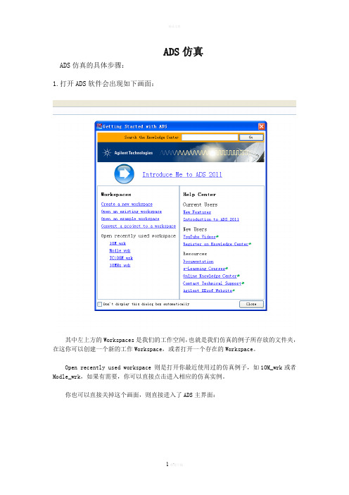
ADS仿真ADS仿真的具体步骤:1.打开ADS软件会出现如下画面:其中左上方的Workspaces是我们的工作空间,也就是我们仿真的例子所存放的文件夹,在这你可以创建一个新的工作Workspace,或者打开一个存在的Workspace。
Open recently used workspace 则是打开你最近使用过的仿真例子,如10M_wrk或者Modle_wrk,如果有需要,你可以直接点击进入相应的仿真实例。
你也可以直接关掉这个画面,则直接进入了ADS主界面:在这你可以通过菜单栏的File--->new--->workspace 来新建一个仿真实例等效于工具栏中的也可以选择File--->open--->workspace 来打开一个存在的仿真实例等效于工具栏中的2.建立一个ADS仿真实例通过File--->new--->workspace来新建一个仿真实例并命名为Newworkspace_wrk如下图所示:然后完成出现如下界面:这时已经出现了Newworkspace_wrk文件夹。
接下来我们就可以在这个文件夹下建立相应的ADS仿真原理图(即Schematic)了。
通过File-->new-->Schematic或者直接点击工具栏的则出现如下窗口:其中被选中的cell_1是默认的Schematic名称,我们可以将它更改成10M。
这时会产生一个新的窗口:这就是我们建立仿真原理图和执行仿真的窗口。
在此窗口的Lumped-Components目录下我们可以选取原理图所需要的电阻,电容以及电感。
在Sources-Freq Domain目录下则可以选中我们需要的直流电压源V_DC。
在Passive-RF Circuit目录下选择晶振XTAL2。
在元器件放置到原理图中通常位置都不是我们想要的,因此要对其做相应的调整,选中一个元器件并单击工具栏中的Rotate By Increment 按钮将它顺时针选中90°,也可以使用快捷方式Ctrl+R。
CV-IOT网关模块桌面应用程序指南说明书
ContentsIntroduction (4)App Initialization (5)Onboarding devices (7)Update Firmware and configure CV-IOT modules (9)Step 1: Hardware (9)Step 2: Install IP Scanner (10)Step 3: Record Server IP Address (PC) (10)Step 4: Record Device IP Addresses (CV-IOT Module) (11)Configure Module (11)Update Client Application (13)Upgrade Client Firmware (13)Check Client Info (13)Test Communication between CV-IOT module and Desktop App (14)Step 1: CV-IOT module (14)Step 2: Database view (14)Step 3: CV Desktop App (14)Configuring Static/ Dynamic IP of the CV-IOT Modules (15)Static IP (16)Dynamic IP (19)Initial Startup (19)Change / Setup New Mongo DB Server Address (21)Configuring Email Address (23)Global Cartridge Configuration (24)Alert Configuration (25)Dashboard View (26)Database View (26)Query/Live Mode (26)Filtering (27)Summary (28)Joint Detail (28)Graph (29)Productivity (29)Extract & Email Operations data (29)Admin View (31)Average Tip Life (31)Tip Deployment by Geometry and Station (31)Warranty (33)IntroductionThe Metcal CV-IOT App provides the user the ability to monitor, analyze, and configure Connection Validation™ smart soldering units in the field.The CV-IOT module generates two types of packets to the Mongo database:•Operational data packetThe operational data packet contains joint specific information containingjoint count, and the power and temperature profile of the joint.•System status data packetThe system status data packet contains information about the CV SolderingPSU connected to the IoT module. The packet contains system on/idling status.The App is organized into three pages:•Dashboard viewThe “Dashboard view” provides a snapshot of the soldering activities on thefloor as a productivity and resource utilization chart when the Metcal CV-IOTApp is installed as a standalone app. When the app is opened for the veryfirst time, the user will be prompted to enter the address of the Mongodatabase server to access the records.•Database viewThe “Database view” provides the user systems ope rations data containing information on every solder joint made using the units in the field, with aninterface to view, query, and analyze. The database view shows operational data packets from the CV-IOT unit. Navigate to “Database view” using the“Details” button.•Admin view.The “Admin view” is available through authenticated login to the systemconfiguration for configuring the unit IP address, mongo DB address pointer, email, and alert configuration. The admin view shows system status packets.Navigate to “Admin view” using “Admin” button.It is strongly suggested that the app be configured in the PC with a“Complete installation” to perform onboarding. Refer to “Installat ionManual_141.docx” for installation instruction.App Initialization•Initially the desktop app starts with the Mongo address“mongodb://127.0.0.1:27017”. The “Mongo Server Unavailable” prompt willappear if the machine running the app is not also running the Mongodbdatabase.•In the settings page, set the application type to “Server” if it is being installed on the system with Mongo server / full installation. For installation onsecondary systems that access the database, install the application withdefault setting as “Client.” There should not be more than one application with “Server” type accessing the same database as it will result in incorrect average tip life calculations.•If the Mongo server is available and the address is set correctly, the application will start normally, otherwise it will start with the “Mongo Server Unavailable” prompt.•Wait for the desktop application to start.•Authentication is not enabled in the Beta release. Please leave the default option “Disable” checked.Onboarding devicesThe user must be logged in as administration in “Admin view” to perform onboarding.•Step 1: Login into the system as administrator for “Admin view” using “Admin” button.•Step 2: The default username and password is “Admin”, “Admin”.•Step 3: Press on “Onboarding D evices” button to configure CV-IOT units.•Step 4: Use configuration interface to setup units.Update Firmware and configure CV-IOT modules Step 1: Hardware•Setup the hardware per wire diagram below.•Power up the CV-IOT Module and the CV System.Step 2: Install IP Scanner•Advance IP scanner is a tool to find computing device attached to your network. It will be used to find the CV-IOT module you have connected, and is available at the website: https:///•Double-Click to Install Advanced_IP_Scanner_x.x.xxxx.exe.Note: If asked to allow the application to make changes to your computer,click “Yes.”Step 3: Record Server IP Address (PC)•If the database is located on the computer running the app, you will need to determine the IP address of that computer.•From the Windows Start Menu, open the Command Prompt.•From the command line of the Command Prompt, type in <ipconfig>.In this example, IP address: 172.16.40.87Step 4: Record Device IP Addresses (CV-IOT Module)•Find the IP address of the client module by running the Advanced IP Scanner and looking for the MAC address that matches with the MAC address printed on the back of the unit.•Record client IP (CV-IOT Module) address. In this example, the MAC address is 9C:65:F9:1E:3D:0E, and the IP address is 172.16.41.10Configure Module•This wizard enables configuring server IP in the Client.•Select the Time zone of the unit from the dropdown menu.•Enter Device IP•Enter Server IP•Press “Configure”•The application shows an error if the DEVICE IP/SERVER IP field is empty or has incorrect value.•If the input values are correct, t he application responds with “True” to show the configuration was successful.Update Client Application•Press “Appln Upgrade”•The application shows an error if the device is empty or has incorrect value.•If the input values are correct, t he application responds with “True” after updating to the latest application firmware.In the case that OK International/Metcal has issued a newer firmware, the new release can be copied into folder “C:\Users\Public\Metcal IoT Platform\firmware” and then if the operator performs the ONBOARDING / APPLN UPGRADE function, the new firmware will be installed into the CV-IOT module.Upgrade Client FirmwareNote: This feature has been removed in most installations.•This wizard supports upgrading the client firmware package.•Enter Device IP•Press “Firmware Upgrade”▪The application shows an error if the device is empty or hasincorrect value.▪If the input values are correct, the application responds with“True” to show that latest application.Check Client Info•This wizard supports reading firmware revision and time zone information from the client.•Press “Firmware Upgrade”•The application asserts violation if the device is empty or has incorrect value.•If the input values are correct, the application displays software revision and time zone information on UI.Test Communication between CV-IOT module and Desktop App Step 1: CV-IOT module•Check if the CV PS is connected through the USB port to the CV-IOT module.•Check if the CV-IOT module is connected to the internet.•Reboot the CV-IOT Module.•Wait for the CV PS to reboot.•Perform a solder joint.Step 2: Database view•Navigate to database view using “Details” button in dashboard.Step 3: CV Desktop App•In the Detail View, you may click the green “refresh” button in the bottom left corner of the CV desktop to continuously view the latest data from the CV.Configuring Static/ Dynamic IP of the CV-IOT Modules •Step 1: Login into the system as administrator for “Admin view” from dashboard. The default settings to login is “Admin”, “Admin”.•Step 2: Select the station to update IP address. The default IP configuration in units is dynamic.•Step 3: Select “Detail” button at the bottom of the page.Figure 1: Admin View - Station Status•Step 4: In the “Detail” view, press the “Configure” button next to the ip address.Figure 2: Configuration page with available configuration settings•Step 5: The “IP Configuration” page will open up with display set “Dynamic”checked/unchecked.o if the current IP address is “Dynamic,” this box will be unchecked and system provides the user fields to enter the “IP address,”“Netmask,”and “Gateway” to set the current unit with “Dynamic IP” to “Static IP.”If the current IP address is “Static.” this box will be checked, and system does not require any other input from user. When “Submit” is pressed, the unit IP will change from “Static IP” to “Dynamic IP.”Static IP•Step 1: To set the unit to “static IP” enter the IP address, netmask, and gateway. These fields must be obtained from the Network Administrator.o The field values to test on OKI-CYPRESS network.▪IP Address: 172.16.40.127▪Netmask: 255.255.248.0▪Gateway:172.16.0.1Figure 3: Fields required for configuring Static IP•Step 2: Press “SUBMIT” and wait.•Upon configuration the app will display a “Success / Fail” message.•Wait for the System to reboot and establish connection with the database. In the meantime, close the popup, exit to D ashboard view using “Cancel” and “logout” button to see the joints generated by the unit with “Static IP”.Figure 4: Successful Static IP Configuration MessageFigure 5: Failed IP Configuration Message•Note:o If the address field is empty or incorrect, the system will provide an error pop-up.o If an error occurs, and the app cannot detect the condition, the system could possibly be configured with the wrong IP, making itunresponsive on the network. This requires manual intervention toreset the IP through the serial port.Figure 6: Flag Error for Invalid StringDynamic IP•Step 1: To set a unit with previously “static IP” to “dynamic IP”, the app will show an unchecked “Dynamic” box. Simply press Submit and wait for the app to display success/error message.•Wait for the System to reboot and establish connection with the database. In the meantime, close the popup, exit to D ashboard view using “Cancel” and“logout” button to see the joints generated by the unit with “Dynamic IP”.Figure 7: Successful Dynamic IP Configuration MessageInitial StartupWhen the Metcal CV-IOT App is installed as a standalone app and it is opened for the very first time without an active database on that computer, it will prompt the user to enter the address of Mongo database server to access the records.When “Close” is pressed, the database configuration page opens to allow the userto configure the database address.Please note: the authenticated “Mongo” database login is not supported in the current revision. Leave the authentication check box in “Disable” and press “Save.” If the database is available, the app will load the dashboard. Authentication is not enabled in the Beta release. Please leave the default option “Disable” checked.Change / Setup New Mongo DB Server AddressThe database address can be reconfigured anytim e in the future using “Admin view.” The steps for configure/reconfigure Mongo address is as follows:•Step 1: Navigate from “Dashboard” to “Admin view” and login as Admin. The default settings to login is login:“Admin”, password:“Admin”.•Step 2: Press “Settings” button in the footer of the page.Figure 8Admin View: DB Configuration•Step 3: Obtain the address of the Mongo Server from your IT department or other authority if you are using a Mongo server on another machine,otherwise it will be your IP address if it is a local installation.•Step 4: Enter the Mongo DB address and port in the field. Leave the authentication field unchecked and user and password fields empty. MongoDB port must always be set to 27017, unless sharding is used (not usedcurrently).Note: To use TLS authentication, the CV-IOT unit needs additional certification packages installed to log data to Mongo server with authentication enabled. As itis not preinstalled currently in the kernel in all modules, the authenticationfeature is not used currently in the app.•Step 5: The interface shows an error when empty fields submitted at the configuration interface.Figure 9: Mongo DB Address InterfaceFigure 10: String validation errorIn the settings page, set the application type to “Server” if it is being installed on the system with Mongo server/full installation. For installation on secondary systems that access the database, install the application with default setting as “Client.” There should not be more than one application with “Server” type accessing the same database as it will result in incorrect average tip life calculation.Configuring Email Address•Step 1: From the dashboard, login into the Admin page.•Step 2: Select the “Email” button from the footer.Figure 11: Configuring Email•Step 3: Configure the email address that will serve as sender or ‘smtp relay’ for this app. Obtain the “SMTP” server details from the email provider,generate key/ password for configuring email.•Step 4: Enter the configuration details and press “Submit” to save the configuration details.•Step 5: Try to extract and send email as shown in the next section. If email is not sent correctly, check the configuration details, re-enter configurationdetails and submit again.Figure 12: Email Address SettingGlobal Cartridge Configuration•Step 1: From the dashboard, login into the Admin page.•Step 2: Select “GCP” to set tip life monitoring parameters.•Step 3: To set a cartridge End of Life (EoL) find the row with that cartridge and cha nge the item in the ‘End of Life’ column to ‘true.’•Step 4: To save and exit, click ‘Save.’ To exit without saving click ‘Close.’Alert Configuration•Step 1: From the dashboard, login into the Admin page.Figure 13: Alert Configuration•Step 2: Set up alerts to be monitored by the app.•Step 3: Note: Alert Intervals are not implemented in this version.Currently only cartridge change notification is the only alert monitored by app.The email is sent only once at the time of event.Figure 14: Alert Configuration InterfaceDashboard View•Step 1: Overall Productivity and Station productivity chart can be viewed for different time period (weekly/monthly) by changing the drop-down menu.•Step 2: Chart can be zoomed in and out by double clicking on the chart.•Step 3: Station specific details can be obtained by double clicking the pie chart.Database ViewQuery/Live Mode•Live Mode: To view soldering data coming from the station. The screen refreshes every 20 sec for new data.•Query mode: To apply filters on the data in database.Filtering•Filters are provided to search the database for information about a specific time period/cartridge or station. The CV-IOT App supports simple filtering.•Step 1: Select “Filter” from the header for the dropdown filter options to appear.•Step 2: Select a Filter from the dropdown menu.•Note that Filtering only works in when the Database view is in Query mode, not in Live mode.•Data in the database view is displayed as pages with a maximum of 100 records per page, with total number of pages displayed the footer.•Data in the database can be viewed by transitioning from current pages to another page using “+” and “-“.Summary• A brief summary of data in the database can be obtained by using the “Summary” button in the footer.•Summary is displayed as chart.Joint Detail•Joint details can be viewed in detail by highlighting the row and pressing “Tab data” button/ double clicking on the row.•All the information about the joint is displayed on a single page.Graph•Power and Temperature graph of each joint can be view by selecting the row and pressing the “Graph” button in the footer.•Multiple joints characteristics (max 3 joints) can be compared by unclicking “Single Selection” checkbox in the footer.Productivity•Productivity of joints is displayed based on Cartridge and time period can be graphed using “Productivity” button in the footer.Extract & Email Operations data•Step 1: Log into the system as administrator for “Admin view”. The default settings to login is “Admin”, “Admin”.•Step 2: Ensure that the system is not “Live” mode.•Step 3: Enter e-mail address and press send.•Step 4: Pop-up confirmation is sent on successful or failed transmission of email.Please note: Only the collection of operations data information from thedatabase is emailed to the customer.Figure 15: Extract & EmailFigure 16: Send Email ConfirmationIf the email field is empty, the window opens to allow the user to perform extraction of data to local folder, archive complete DB, drop database and load demo database.Admin View•Step 1: Filtering based system status and station type / cartridge is provided in the “Admin view”.•Step 2: Detailed view of station status can be viewed by selecting the record and pressing “Detail” in the footer.•Step 3: The detail view provides option for the user to configure station type / cartridge type as “LEAD/LEAD-FREE”, station description and IP address.Average Tip Life•The graphic shows the aggregate/average life of tips for each geometry.•When cartridge EoL is forced, the Average tip life does not increment if the cartridge is not used after that time. However, if the cartridge is continued to be used after forced EOL, the average tip life increments to reflect the real-time use.Tip Deployment by Geometry and Station•Step 1: From the dropdown menu select tip deployment by geometry to display the number of tips used / in use for 7 days, 30 days, 90 days and 1-year works.•Step 2: From the dropdown menu select tip deployment by station to display the number of tips user per station in use for 7 days, 30 days, 90 days and 1-year works. Double click on the bar to display the number of tips based on tip geometry.•Change the selected in “Global Configuration Page” through Admin login and see the tips displayed change based on selection.WarrantyOK International warrants this product against any defects in material or workmanship for (1) year from the date of purchase by the original owner. This Warranty excludes normal maintenance and shall not apply to any opened, misused, abused, altered, or damaged items. If the product should become defective within the warranty period, OK International will repair or replace the product free of charge as its sole option. The repaired or replacement item will be shipped, freight prepaid, to the original purchaser. The warranty period will start from the date of purchase. If the date of purchase cannot be substantiated the date of manufacture will be used as the start date of the warranty period.Metcal Corporate Headquarters 10800 Valley View Street, Cypress, California, 90630, USA Tel: 1-714-799-9910 Fax: 1-714-828-2001 For Sales& SupportVisit our website for more information and to contact the Metcal office nearest you. /contact-us。
ADS系列空气与尘分离器说明书

ADS Series Air & Dirt SeparatorsFurnish and install, as shown on plans, a Model _________________ Air & Dirt Separator. The unit shall have ____________(NPT/flanged/grooved) inlet and outlet connections. A 2” NPT vent connection shall be fitted to the top of the vessel to enable installation of an air vent, and a 2” NPT blowdown connection shall be fitted to the bottom to enable draining and purging of debris. Separator shall have all steel body construction.The unit shall have a mesh filter assembly consisting of multiple concentric stainless steel screens with the capability of separating dirt particles as small as 5 microns. The mesh shall be of the welded, overlapping type to promote microbubble adhesion and minimize readmission into the flow stream. The core of the filter assembly shall include a diverter tube to reduce fluid velocity and enhance mesh contact. The separator shall be capable of removing 98% of free air in one pass.If specified to include a Magnetic Separator (option M), the unit shall include a nominal 1” diameter, rare-earth magnet rod capable of attracting and purging ferrous particles, including magnetite. A blowdown tee fitting for the purging of debris shall be provided at the bottom of the unit. The 2” NPT horizontal discharge shall be compatible with manual or automatic valve types. The magnetic separator must be vertical and centrally located to maximize ferrous particle capture. Offset and angled magnets shall not be allowed. The assembly shall include a non-ferrous dry well and removable magnet rod with a plastic handle to facilitate safe handling in an active system.The separator must be designed, constructed, and stamped for (125) (150) (_____) psig at 350°F (177°C) in accordance with section VIII, Division 1 of the ASME Boiler and Pressure Vessel Code, and registered with the National Board of Boiler and Pressure Vessel Inspectors. The separator shall be include a base coat of red oxide primer.A manufacturers’ Data Report for Pressure Vessels, Form U-1 as required by the provisions of the ASME Boiler and Pressure Vessel Code shall be furnished for each separator upon request.© 2019 Worthington Industries Inc. MC10292 (06/19)1400 Division Road, West Warwick, RI USA 02893T: 800.426.8765 。
ADS设计VCO范例(资料不错)
ADS设计VCO范例(资料不错)应⽤ADS 设计VCO1.VCO 振荡器的基本知识和相关指标1.1振荡器的分类:微波振荡器按器件来分可以分为:双极晶体管振荡器;场效应管振荡器;微波⼆极管(踢效应管、雪崩管等)振荡器。
按照调谐⽅式分可以分为:机械调谐振荡器;偏置调谐振荡器;变容管调谐振荡器;YIG 调谐振荡器;数字调谐振荡器;光调谐振荡器。
1.2 振荡器的主要指标:①振荡器的稳定度:这⾥⾯包括:频率准确度、频率稳定度、长期稳定度、短期稳定度和初始漂移。
频率准确度是指振荡器实际⼯作频率与标称频率之间的偏差。
有绝对频率准确度和相对频率准确度两种⽅法表⽰。
绝对频率准确度:)(0Hz f f f -=?其中f -实际⼯作频率;0f -标称频率。
相对频率准确度式绝对频率准确度与标称频率准确度的⽐值,计算公式为:)(000Hz f f f f f -=? ②频率稳定度:频率稳定度是指在规定的时间间隔内,频率准确度变化的最⼤值,也有两种表⽰⽅法:绝对频率稳定度和相对频率稳定度。
频率稳定度还可以分为长期频率稳定度、短期频率稳定度和瞬间频率稳定度。
③调频噪⾳和相位噪⾳:在振荡器电路中,由于存在各种不确定因素的影响,使振荡频率和振荡幅度随机起伏。
振荡频率的随机起伏称为瞬间频率稳定度,频率的瞬间变化将产⽣调频噪⾳、相位噪⾳和相位抖动。
振荡幅度的随机欺负将引起调幅噪⾳。
⼀次,振荡器在没有外加调制时,输出的频率不仅含振荡频率f 0,在f 0附近还包含有许多旁频,连续分布在f 0两边。
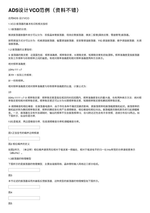
如下图所⽰,纵坐标是功率,f 0处是载波,两边是噪⾳功率,包括调频噪⾳功率和调幅噪⾳功率。
图1正弦信号的噪声边带频谱图2 相位噪声的定义如图2所⽰,(单边带)相位噪声通常⽤在相对于载波某⼀频偏处,相对于载波电平的归⼀化1Hz带宽的功率谱密度表⽰(dBc/Hz)。
1.3振荡器的物理模型下图所⽰的是振荡器的物理模型,主要由谐振⽹络、晶体管和输⼊⽹络这三部分组成。
CVW 全高清低延迟通墙IP流音视频传输设备用户操作指南 V1.0说明书
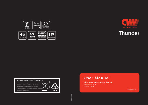
Structure & Interface
TX: 7074
Antenna Interface
Battery Interface
OLED Display MODE RESET LAN
SDI LOOP Out
SDI In DC-IN
Power Switch
Transmitter Key Operation
RESET
Press the “RESET” button for about 3s
During the restart of the coding-decoding board, the “RESET” string will always be displayed on the OLED display, and the string will disappear after the restart.
Thank you for choosing CVW's professional wireless HD audio and video transmission product. Read the following precautions carefully before using this product: 01
01
* Do not use this product for a long tiห้องสมุดไป่ตู้e in the sun or dusty place.
01
* Be sure to use this product within the temperature and humidity ranges.
02 * Do not operate the product under vibration or strong magnetic fields.
ADS软件的使用手册编写及应用_1_
ADS软件的使⽤⼿册编写及应⽤_1_ADS软件的使⽤⼿册编写及应⽤⼀.关于ADS软件⼀)ADS中的projects当⽤户对ADS中的designs进⾏建⽴,模拟和分析以完成设计任务时,将会产⽣⼀定量的数据,⽽projects正是对这些数据进⾏⾃动的组织和存储。
⼀个project包括:电路(circuit),版⾯(layout),模拟(simulation),分析(analysis)以及由于⽤户建⽴的designs和projects之间的连结⽽产⽣的designs的输出信息。
使⽤ADS的主窗⼝可以建⽴或打开projects。
当⽤户登陆ADS时,主窗⼝将被打开。
⼆)ADS中的designsADS中的designs是⽤来存储⽤户为完成设计任务⽽⽣成的原理图及版⾯设计信息。
⼀个designs包括:⼀个单独的原理图或电路图,或者包括若⼲原理图或电路图嵌⼊式的包含于⼀个单独的design中。
所有的designs都可以直接从主窗⼝打开或者从design窗⼝打开。
在⼀个design窗⼝中,⽤户可以做以下事情:建⽴或修改电路图和布线图增加变量和等式配置电路元件和模拟控制器制定版⾯,选择参数添加注释以及例证从电路中产⽣版⾯(版⾯中产⽣电路图)三)ADS中的模拟ADS软件提供模拟控制器功能,以便⽤户可以添加或配置模拟来测试⽤户的设计。
对于DSP设计来说,当⼀个模拟/射频设计仿真需要⼀个或多个不同的控制器时,就需要⼀个数据流控制器。
⽤户可以⾃⼰添加合适的控制器,也可以插⼊⼀个包含合适控制器的模板(template)。
模拟控制器的分类:1.数据流控制器:在使⽤Agilent Ptolemy模拟器时,⽤来控制混合同步数字信号来进⾏数字信号处理。
适⽤于所有的DSP设计。
2.DC :是射频/模拟电路设计模拟的基本控制器,提供拓扑检测和直流分析的功能。
适⽤于所有的射频/模拟设计。
3.AC:获得⼩信号转换参数,如电压增益,电流增益,线性电压或电流噪声。
欧姆科技 CIO-DAS80x 数据采集器说明书
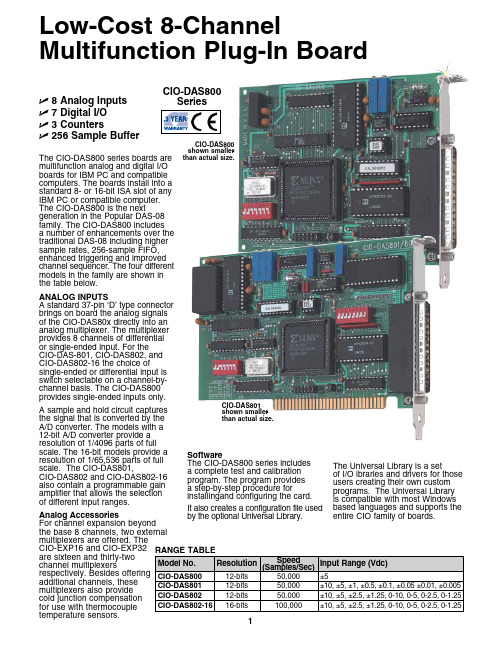
1ANALOG INPUTS A standard 37-pin ‘D’ type connector brings on board the analog signals of the CIO-DAS80x directly into an analog multiplexer. The multiplexer provides 8 channels of differential or single-ended input. For the CIO-DAS-801, CIO-DAS802, and CIO-DAS802-16 the choice of single-ended or differential input isswitch selectable on a channel-by-channel basis. The CIO-DAS800 provides single-ended inputs only.A sample and hold circuit captures the signal that is converted by the A/D converter. The models with a 12-bit A/D converter provide a resolution of 1/4096 parts of full scale. The 16-bit models provide a resolution of 1/65,536 parts of full scale. The CIO-DAS801, CIO-DAS802 and CIO-DAS802-16 also contain a programmable gain amplifier that allows the selection of different input ranges.Analog Accessories For channel expansion beyond the base 8 channels, two external multiplexers are offered. The CIO-EXP16 and CIO-EXP32 are sixteen and thirty-two channel multiplexers respectively. Besides offering additional channels, these multiplexers also provide cold junction compensation for use with thermocouple temperature sensors.Software The CIO-DAS800 series includes a complete test and calibration program. The program provides a step-by-step procedure for installingand configuring the card.It also creates a configuration file used by the optional Universal Library.The Universal Library is a set of I/O ibraries and drivers for those users creating their own custom programs. The Universal Library is compatible with most Windows based languages and supports the entire CIO family of boards.U 8 Analog InputsU 7 Digital I/OU 3 CountersU 256 Sample Buffer The CIO-DAS800 series boards are multifunction analog and digital I/O boards for IBM PC and compatible computers. The boards install into a standard 8- or 16-bit ISA slot of any IBM PC or compatible computer. The CIO-DAS800 is the next generation in the Popular DAS-08 family. The CIO-DAS800 includes a number of enhancements over the traditional DAS-08 including higher sample rates, 256-sample FIFO, enhanced triggering and improved channel sequencer. The four different models in the family are shown in the table below.CIO-DAS800 shown smaller than actual size.Low-Cost 8-Channel Multifunction Plug-In Board CIO-DAS801 shown smaller than actual size.CIO-DAS800 SeriesDIGITAL I/OInputs: 4-bitsInput Voltage: Low = 0.8 V max., High = 2.0 V min @20µA Outputs: 4-bitsOutput Voltage:Low=**************(sink), High=*************** (source)COUNTER/TIMERCounters:Three 16-bit down counters Type: 82C54Input Frequency: 10 MHz max. ENVIRONMENTAL Temperature Range:0 to 50°C (operating),-20 to 70°C (storage)Humidity: 0 to 90%non-condensingOMEGACARE SM extended warranty is available for models shown on this page.Ask your sales representatives for full details when placing order.Ordering Example:CI0-DAS802-16 board, CIO-TERMINAL screw terminal panel, OMEGACARE SM 1 year extended warranty for CIO-DAS802-16 (adds 1 year to standard 3 year warranty)and C37FF-2 cable.SpecificationsAnalog InputChannels: 8 single-ended or differential(CIO-801/802 and CIO-DAS802-16), 8 single-ended(CIO-DAS800) Resolution: 12-bit (CIO-DAS800 and CIO-801/802), 16-bit(CIO-DAS802-16)Accuracy: 0.01% of reading±1bit(CIO-DAS800 andCIO-801/802), 0.0015% of reading ±1.5bit (CIO-DAS802-16)Sample Speed: 50,000 samples/s(CIO-DAS800 andCIO-801/802), 100,000 samples/s(CIO-DAS802-16)Input Range: See range table Overvoltage: ±30 VLinearity: ±1-bit (CIO-DAS800 and CIO-801/802), ±1.5-bit CIO-802-16) Impedance: 100MW CIO-DAS802-16 shown smaller than actual size.An optional driver for LabViewis also available. The LabViewdriver works in conjunction withthe Universal Library, so bothare needed to use theCIO-DAS80x in LabVIEW.The CIO-DAS80x is alsocompatible with manyoff-the-shelf programsincluding Labtech, DASYLaband SnapMaster.2。
ADC ADSCOPE 医学液晶诊断仪用户指南说明书
Adscope®SpragueUso, cura emanutenzioneGrazie per aver scelto uno stetoscopio ADC® ADSCOPE®. Il tuo nuovo stetoscopio ADC®ADSCOPE® è progettato per offrire una sensibilità acustica insuperabile, una durata senza eguali e un comfort impareggiabile. Ogni componente è stato accuratamente progettato per massimizzare le prestazioni.Descrizione del dispositivo e uso previstoQuesto dispositivo è destinato esclusivamente a scopi diagnostici medici. Può essere usato per ascoltare il cuore, i polmoni e altri suoni corporei, oltre che per normale auscultazione. Il dispositivo non è progettato, venduto o destinato all'uso eccetto quanto indicato.Avvertenze generaliUna dichiarazione di avvertenza in questo manuale identifica una condizione o una pratica che, se non corretta o interrotta immediatamente, potrebbe portare a le-sioni, malattie o morte del paziente.ATTENZIONE:non utilizzare mai lo stetoscopio senza i tappi auricolari saldamente bloccati in posizione.NOTA:quando si spacchettano per la prima volta, i tubi Sprague potrebbero subire contrattempi dalla confezione.E 'normale. Per scoprire, appendere l'oscilloscopio per 24 ore a temperatura ambiente..Opzioni del toraceIl design ADC® Sprague utilizza cinque diversi supporti intercambiabili per il torace (3 campane e 2 diaframmi) per rilevare un'ampia gamma di frequenze in pazienti sia pediatrici che adulti. Il tamburo del pettine è in grado di alloggiare contemporaneamente 2 diversi accessori per il torace di vostra scelta. Selezionare il tipo che meglio si adatta all'appli-cazione paziente desiderata.Gli attacchi del cestello possono essere attaccati filettando in senso orario fino a stringere. Per rimuovere, ruotare in senso antiorario. (Figura 1)Selezione della cassaSu ADC® ADSCOPE® Spragues, l'intera capsula ruota di 180 °consentendo la selezione di un lato. (Solo un lato è operativo alla volta). Il meccanismo a valvola brevettato di ADC® elimina prati-camente tutte le perdite acustiche dal lato inutilizzabile.Per selezionare il lato in funzione, tenere il gambo del pettorale in una mano e ruotare il pettorale con l'altra mano fino a sentire un clic. Un leggero tocco sul diaframma o sulla campana aiuterà a determinare quale lato è in funzione.Gruppo diaframma adulto -per filtrare le frequenze più basse e accentuare le gamme più elevate negli adulti.Gruppo diaframma pediatrico-per rilevare soffi acuti nei neonati e nei bambini.Campana da 1 1/4 "- per rilevare suoni e mormorii bassi e medi negli adulti.1 "campanello -per rilevare suoni e mormorii bassi e medi nei bam-bini..3/4 "campanello - per rilevare suoni e mormorii bassi e medi nei bam-bini.Diaframma adultoattivatoattivatoChiave della cassaIl design brevettato e la chiave a fessura di ADC® con-sentono di serrare il gruppo pediatrico o adulto in modo si-curo come desiderato (per ridurre il rischio di perdita) senza timore di non riuscire a smontare il bordo per sostituire un diaframma usurato o rotto ( un problema che spesso affligge gli ambiti Sprague meno costosi)..Sostituzione del diaframmaferrandolo saldamente e ruotandolo in senso antiorario.Per allentare il bordo del diaframma, inserire la chiave nelledue fessure situate all'interno della porzione filettata, situata sul lato in-feriore del gruppo. Tenendo fermo il cerchio, girare la chiave in sensoantiorario per allentare il cerchio. Rimuovere il diaframma indossato esostituirlo con uno nuovo. Rimontare il bordo e stringere ruotando lachiave in senso orario fino a serrare. Quindi riassemblare il bordo deldiaframma sul tamburo del torace ruotandolo in senso orario fino a serrarlo.Regolazione della tensione della molla nei Binaurals Array Per ridurre la tensione, afferrare saldamente i binaurali con en-trambe le mani con le dita alla base del biauricolare, i pollici suciascun lato appena prima che i binaurali incontrino il tubo. Flet-tere la molla binaurale gradualmente fino a ottenere la tensionedesiderata. Per aumentare la tensione, afferrare i binaurals nellamano e stringere i tubi biauricolari gradualmente.Attenzione:un'eccessiva regolazione della tensione della molla potrebbe indebolire la molla.Cura e manutenzione• Evitare calore estremo, freddo, solventi o oli.• NON lasciare esposto alla luce solare diretta per periodi di tempo prolungati.• Binaurali e tubi possono essere puliti con alcool o acqua saponata delicata.• I auricolari possono essere svitati dai binaurali per una pulizia accurata.• Controllare periodicamente che i tappi auricolari siano ben fissati ai binaurali.• NON immergere lo stetoscopio in alcun liquido o soggetto alla sterilizzazione a vapore.• Se la sterilizzazione è necessaria, sterilizzare a gas solo.141517182134865791213101116Numero di riferimento1Codice articolo 640-01D Nome della parteAssemblaggio del tamburo della cassa Quantità1Elenco delle parti di ricambioGARANZIA LIMITATAAmerican Diagnostic Corporation (ADC®) garantisce i propri prodotti contro difetti di ma-teriali e lavorazione in condizioni di uso e manutenzione normali come segue:1. Il servizio di garanzia si estende all'acquirente al dettaglio originale e inizia con la data di consegna.2. Lo stetoscopio ADSCOPE® Sprague è garantito per cinque anni dalla data di acquisto (tutte le parti).Cosa è coperto:sostituzione di parti e manodopera.Cosa non coperto: Spese di trasporto da e verso ADC®. Danni causati da abuso, uso improprio, incidente o negligenza. Danni accidentali, speciali o consequenziali. Alcuni stati non consentono l'esclusione o la limitazione di danni incidentali, speciali o consequenziali, pertanto questa limitazione potrebbe non essere applicabile.Per ottenere il servizio di garanzia:inviare l'articolo (s) affrancatura pagato a ADC®, Attn: Repair Dept., 55 Commerce Dr., Hauppauge, NY 11788.Si prega di includere il proprio nome e indirizzo, numero di telefono, prova di acquisto e una breve nota spiegando il problema.Garanzia implicita:qualsiasi garanzia implicita deve avere una durata limitata ai termini della presente garanzia e in nessun caso oltre il prezzo di vendita originale (ad eccezione di dove proibito dalla legge).Questa garanzia ti conferisce diritti legali specifici e potresti avere altri diritti che variano da stato a stato.ADC55 Commerce Drive Hauppauge, NY 11788 ADC (UK) Ltd. Unit 6, PO14 1TH United KingdomIspezionato negli Stati Uniti.Fatto in Cina tel: 631-273-9600numero verde: 1-800-232-2670fax: 631-273-9659 *****************Questo manuale è disponibile online in una varietà di lingue, seguire i link per leopzioni di lingua:/carePer registrare il tuo prodotto, visita il nostro sito:/registerPER DOMANDE, COMMENTI, O SUGGERIMENTI CHIAMATA GRATUITA:1-800-ADC-2670 OPPURE VISITARE:/feedback。
VirtuoZoAds操作流程

数据准备
经过加密的ADS40一级影像,主要数据包 括: sup、odf、cam(相机文件)、ads(影 像文件); 坐标系参数; gcp(七参数文件); bin(高程修正文件)。
外业
内业
平面转换7参数:飞行坐标系统(WGS84)到产品所在坐标系统的转换参数。
一般,数据提供方会提供这7个参数的文本文件,用户只需手工输入即可; 若没有提供这7个参数,需要用控制点来解算这7个参数,一般至少需要6 个控制点。
2、创建立体模型。
单击菜单“模型管理”,选择划分模型的方式。有以下四种方式: 按标准图幅划分:根据标准图幅的定义和图幅格式划分模型。
用户可以选择图幅比例尺和图幅格式,外扩范围(单位为米)。单击“确认”, 划分的模型,会自动显示图幅名称。
程序会自动读取“前视、下视、后视”的sup文件;也可以手工输入, 从右侧影像列表中选中文件,单击左侧相应的
可以不设置正射 影像要采用的影像 文件,如果没有相 应的文件,选中下 视影像即可(一般 用下视影像来生成 正射影像)。 注意:检查左侧文件是否正确对应
内业
单击坐标文件右边的按钮,弹出如下对话框,设置坐标文件的文件名和路径:
内业
飞行坐标系统(WGS84):默认项,不用设置。 产品坐标系统:设置产品所在的坐标系统,包括系统的椭球信息和投影信息。 如下图所示:
单击“中央经度计算”,弹出如下图所示对话框:可以进行分带,或者输入经度, 选择单位,程序自动计算出中央经度。
内业
1、新建工程。单击“文件->新建”,
弹出工程参数设置对话框,如下图所示:
参数说明:
Project: 工程名称和路径 Sup path: 原始数据SUP文件路径 ADS Path: 原始数据影像文件路径 Odf Path:原始数据odf文件路径 CAM Path:原始数据相机文件路径,在原始数据相机文件夹(cam)下, 一般有ttc、v001、v002、(v003、v004)文件夹,此选项选择的最 后迭代计算的结果,如v004。
ADC ADSCOPE 诊断耳说明书

Adscope®SpragueGebrauch, Pflegeund WartungDanke, dass Sie sich für ein ADC® ADSCOPE® Stethoskop entschieden haben. Ihr neues ADC® ADSCOPE®-Stethoskop bietet unübertroffene akustische Empfindlichkeit, unübertroffene Haltbarkeit und unvergleichlichen Komfort. Jede Komponente wurde sorgfältig entwickelt, um die Leistung zu maximieren.Gerätebeschreibung und bestimmungsgemäße VerwendungDieses Gerät ist nur für medizinische Diagnosezwecke vorgesehen. Es kann zum Hören von Herz-, Lungen- und anderen Körpergeräuschen sowie zur normalen Auskultation ver-wendet werden. Das Gerät ist nicht für den Gebrauch ausgelegt, verkauft oder vorgesehen, außer wie angegeben.Allgemeine WarnungenEin Warnhinweis in diesem Handbuch identifiziert eine Bedingung oder Praxis, die, wenn sie nicht sofort korrigiert oder unterbrochen wird, zu Verletzungen, Krankheit oder Tod des Patienten führen kann.VORSICHT:Verwenden Sie niemals ein Stethoskop ohne fest einrastende Ohroliven.HINWEIS:Beim ersten Auspacken kann es beim Sprague-Schlauch zu Knickstellen kommen. Das ist normal. Entwirren Sie den Rahmen für 24 Stunden bei Raumtemperatur.BrustoptionenDas ADC® Sprague-Design verwendet fünf verschiedene austauschbare Brustaufsätze (3 Glocken und 2 Membranen), um einen breiten Frequenzbereich bei Kindern und Erwach-senen zu erkennen. Die Brusttrommel bietet Platz für 2 verschiedene Brustaufsätze Ihrer Wahl. Wählen Sie den Typ, der am besten für die beabsichtigte Patientenanwendung geeignet ist.Brustaufsätze können durch Aufschrauben im Uhrzeigersinn bis zum Anschlag fixiert werden. Zum Entfernen drehen Sie gegen den Uhrzeigersinn. (Abbildung 1)Selection of the ChestpieceBei ADC® ADSCOPE® Spragues dreht sich das gesamte Brust-stück um 180 °, so dass eine Seite ausgewählt werden kann. (Nur eine Seite ist gleichzeitig bedienbar). Der patentierte Ventilmecha-nismus von ADC® eliminiert praktisch alle akustischen Lecka-gen von der funktionsunfähigen Seite.Um die Seite in Betrieb zu nehmen, halten Sie den Brust-stückschaft in einer Hand und drehen Sie das Bruststück mit der anderen Hand, bis ein Klicken zu hören ist. Ein leichter Schlag auf die Membran oder Glocke hilft zu bestimmen, welche Seite auch in Betrieb ist.Adult Membrane Assembly -zum Ausfiltern tiefer Frequenzen und zum Akzentuieren der höheren Bereiche bei Erwachsenen.Pediatric Membrane Assembly -zur Erkennung von hohen Geräuschen bei Säuglingen und Kindern.1 1/4 "Glocke - zum Erkennen von tiefen und mittleren Lauten und Gemurmel bei Erwachsenen.1 "Glocke -zur Erkennung von niedrigen und mittleren Töne und Geräusche bei Kindern.3/4 "Glocke - zur Erkennung von niedrigen und mittleren Ton undGeräusch bei Säuglingen.Erwachsene MembranaktiviertPädiatrische MembranaktiviertBrustharnisch-SchlüsselDas von ADC® entwickelte Bruststückdesign undgeschlitzter Schlüssel ermöglichen es Ihnen, die pädiatrischeoder erwachsene Einheit so sicher zu befestigen, wie Siemöchten (um das Risiko eines Verlusts zu verringern), ohnedie Felge auseinanderbauen zu müssen, um eine abgenutzte oder gebrochene Membran zu ersetzen ( ein Problem, das oft weniger kostspielige Sprague-Scopes plagt).Ersetzen der MembranBaugruppe, indem Sie die Baugruppe fest greifen und gegenden Uhrzeigersinn drehen.Um den Membranrand zu lösen, führen Sie den Schlüssel in die zweiSchlitze im Gewindeteil an der Unterseite der Baugruppe ein. WährendSie die Felge ruhig halten, drehen Sie den Schlüssel gegen denUhrzeigersinn, um die Felge zu lockern. Abgenutzte Membrane entfer-nen und durch neue ersetzen. Felge wieder zusammenbauen und durch Drehen im Uhrzeigersinn bis zum Anschlag anziehen. Montieren Sie dann den Membranrand wieder auf der Brusttrommel, indem Sie ihn im Uhrzeigersinn bis zum Anschlag drehen.Einstellen der Federspannung in den Binauralenindem Sie beide Hände mit den Fingern an der Basis des Binau-rals festhalten, Daumen auf jeder Seite, kurz bevor die Binauraleauf den Schlauch treffen. Nach und nach binaurale Feder span-nen, bis die gewünschte Spannung erreicht ist. Um die Span-nung zu erhöhen, greifen Sie die Binaurale in die Hand unddrücken Sie die Binauralschläuche allmählich zusammen.Vorsicht:Übermäßige Einstellung der Federspannung könnte die Feder schwächen.Pflege und Wartung• Vermeiden Sie extreme Hitze, Kälte, Lösungsmittel oder Öle.• NICHT für längere Zeit direktem Sonnenlicht aussetzen.• Binaurale und Schläuche können mit Alkohol oder milder Seifenlauge abgewischt werden.• Ohreinsätze können für eine gründliche Reinigung von den Ohrbügeln abgeschraubt wer-den.• Überprüfen Sie regelmäßig, dass die Ohrpassstücke fest an den Binauralen befestigt sind.• Tauchen Sie das Stethoskop NICHT in Flüssigkeiten oder einer Dampfsterilisation.• Wenn eine Sterilisation erforderlich ist, nur mit Gas sterilisieren.141517182134865791213101116Referen-znummer1Artikel-nummer 640-01D Teilname Brusttrommeleinheit Menge 1ErsatzteillisteEINGESCHRÄNKTE GARANTIEAmerican Diagnostic Corporation (ADC®) gewährleistet, dass seine Produkte bei normaler Verwendung und Wartung wie folgt gegen Material- und Verarbeitungsfehler geschützt sind:1. Der Garantieservice gilt nur für den ursprünglichen Einzelhandelskäufer und beginnt mit dem Lieferdatum.2. Für Ihr ADSCOPE® Sprague-Stethoskop gilt eine Garantie von fünf Jahren ab Kaufdatum (alle Teile).Was ist abgedeckt: Ersatz von Teilen und Arbeit.Was nicht abgedeckt ist:Transportkosten von und zu ADC®. Schäden, die durch Miss-brauch, Missbrauch, Unfall oder Fahrlässigkeit verursacht werden. Neben-, Sonder- oder Folgeschäden. In einigen Staaten ist der Ausschluss oder die Beschränkung von Neben-, Sonder- oder Folgeschäden nicht zulässig, sodass diese Einschränkung möglicherweise nicht auf Sie zutrifft.Um Garantie-Service zu erhalten:Senden Sie Artikel an ADC®, Attn: Reparat-urabteilung, 55 Commerce Dr., Hauppauge, NY 11788. Bitte geben Sie Ihren Namen und Adresse, Telefonnummer, Kaufbeleg und eine kurze Beachten Sie das Problem.Implizite Garantie:Jede implizite Garantie ist zeitlich begrenzt auf die Bedingungen dieser Garantie und in keinem Fall über den ursprünglichen Verkaufspreis hinaus (außer wenn dies gesetzlich verboten ist).Diese Garantie gibt Ihnen bestimmte gesetzliche Rechte und Sie können weitere Rechte haben, die von Staat zu Staat variieren.ADC55 Commerce Drive Hauppauge, NY 11788 ADC (UK) Ltd. Unit 6, PO14 1TH United KingdomIn den USA geprüft.In China hergestellt tel: 631-273-9600gebührenfrei: 1-800-232-2670fax: 631-273-9659 *****************Dieses Handbuch ist online in ver-schiedenen Sprachen verfügbar. Folgen Sie den Links für Sprachoptionen:/careUm Ihr Produkt zu registrieren, besuchenSie uns unter:/registerFÜR FRAGEN, KOMMENTARE ODER VORSCHLÄGE MELDEN SIE KOSTENLOS:1-800-ADC-2670 ODER BESUCHEN:/feedback。
ADS80数字航摄系统操作流程

ADS80数字航摄系统操作流程0 引言ADS80是徕卡公司在2008年7月推出的推扫式数字航摄系统,该系统集成了高精度的惯性导航定向系统(IMU)和全球卫星定位系统(GPS) ,一次飞行就可以同时获取前视、底点和后视三度重叠、连续无缝的全色立体影像以及彩色影像和彩红外影像,独特的设计原理,在测绘生产中对比常规框幅式数字航摄系统具有较大的优势,尽管如此,我们也发现ADS80航摄系统成像完全依赖POS系统,系统组成较为复杂,,空中摄影时操作时设置选项较多,一旦设置错误,可能会对整个航摄架次产生很大的影响,可能造成巨大的经济损失,甚至会造成电子设备的损坏,为此我院利用多年的航摄经验结合ADS80航摄系统实际情况总结出了独具特色的ADS80数字航摄系统操作流程。
1 技术流程组成该技术流程由八个部分组成,每个部分对于航空摄影都至关重要,功能如下:1.飞行前协调飞行前跟领航员的沟通、协调是航空摄影能否顺利进行的重要的部分,飞行前协调包括:(1)对领航员介绍OC50导航界面;(2) 对领航员交代转弯坡度及飞行速度;(3) 对领航员交代GPS领航数据表;(4)对领航员介绍8字飞行方案;(5)其它飞行建议。
2.地面检查地面检查是飞机起飞之前对ADS80航摄系统开机条件进行检查,包括:(1)螺丝连接检查;(2)电缆连接正确检查;(3)打开摄影舱门检查;(4)镜头清洁检查;(5)ADS80按键零位置检查;(6)MM80插入确认检查。
3.地面通电测试检查飞机起飞前ADS80航摄系统需进行的通电测试,以确定其运转正常,航摄参数要在这时设置完成,包括:(1)开启地面电源;(2)打开空气开关;(3)PAV80开关调至REMOTE;(4)SH92开关调至REMOTE;(5)OC50开关调至ON;(6)CU80开关调至ON;(7)CU80 LED显示StartUP;(8)FCMS 主菜单启动是否正常;(9)CU80 LED显示READY;(10)U盘插入CU80;(11)飞行计划导入到CU80中;(12)进入硬盘管理菜单(①清空硬盘数据;②设置硬盘工作模式);(13)配置检查[Hardware](①确认镜头型号为ADS80;②确认MM80工作模式;③确认座架型号为PAV80);(14)配置检查[Global1](①确认时区为+8;②设置偏心分量);(15)进入FCMS飞行菜单;(16)GPS 检测通过;(17)MM80检测通过,存储方式正确;(18)MM80容量检测;(19)CU80检测通过;(20)PAV80检测通过,LED黄橙色;(21)SH92检测通过;(22)0C50显示界面正确;(23)等待4个LED全绿;(24)开始数据记录,数据通道及写入是否正确;(25)取景相机视频状态良好;(26)结束数据记录;(27)飞行计划的导入及检查;(①航线总数是否正确;②飞行高度是否正确;③分辨率是否正确);(28)退出FCMS飞行界面;(29)退出FCMS主菜单,直至CU80系统退出;(30)CU80开关调至OFF;(31)SH92开关调至OFF;(32)PAV80开关调至OFF;(33)0C50开关调至OFF;(34)关闭空气开关;(35)关闭摄影舱门;(36)断开地面电源的连接。
ADC Adscope 600系列医用耳朵式诊断器说明书
Adscope® StetoscopioIstruzioniper l'usoGrazie per aver scelto uno stetoscopio ADC® ADSCOPE®. Il tuo nuovo stetoscopio è progettato per offrire una sensibilità acustica senza pari, una durata senza pari e un comfort senza pari. Ogni componente è stato progettato con cura per massimizzare le prestazioni.Queste istruzioni per l'uso si applicano a tutti i modelli di stetoscopio Adscope: 600, 601, 602, 603, 604, 605, 606, 608, 612, 614, 615, 618 e 619.Descrizione del Dispositivo e uso PrevistoQuesto dispositivo è destinato esclusivamente a scopi diagnostici medici. Può essere utilizzato per l'auscultazione di suoni cardiaci, polmonari, intestinali e di altro tipo. Il dispositivo non è progettato, venduto o progettato per l'uso salvo quanto indicato. Avvertenze GeneraliUna dichiarazione di avvertenza in questo manuale identifica una condizione o pratica che, se non corretta o interrotta immediatamente, potrebbe causare lesioni al paziente, malattia o morte.AVVERTIMENTO: Non utilizzare mai lo stetoscopio senza i tappi delle orecchie bloccati saldamente in posizione.AVVERTIMENTO: Lo stetoscopio contiene piccole parti che possono presentare un rischio di soffocamento.AVVERTIMENTO: La contaminazione incrociata dello stetoscopio potrebbecausare infezione al paziente. Pulire e disinfettare lo stetoscopio tra gli usi come descritto in Pulizia, disinfezione e conservazione.AVVERTIMENTO: Le orecchie possono essere ingerite e causare pericolo di sof-focamento. Accertarsi che tutte le parti siano correttamente collegate e conservate.AVVERTIMENTO: Il tubo dello stetoscopio può essere un pericolo di strangola-mento. Tenere lontano dai bambini.Come utilizzare un petto a frequenza regolabile (modelli AFD - 600, 601, 603, 604, 606, 608, 612, 614, 615, 618 e 619)Gli adscopi con tecnologia AFD forniscono la risposta acustica migliorata di una campana e un diaframma tradizionali. Una guarnizione di gomma attorno al perimetro del diaframma consente di modificare la risposta in frequenza modificando la pressione di contatto.Selezione di una cassa combinata(Modelli a due facciate: 601, 602, 603, 604,605, 606, 608 e 619)Con gli stetoscopi combinati è possibile selezionarel'uso del diaframma per il monitoraggio dei suoni adalta frequenza o della campana aperta per il monitoraggiodella risposta a bassa frequenza.Per selezionare un lato, tenere lo stelo della valvola delcopricapo in una mano e ruotare il copricapo di 180 ° conl'altra mano fino a quando "scatta" in posizione. Lo steloha un punto inciso, che si allinea con il lato attivo.Per confermare quale lato è attivato, toccare leggermenteda un lato, quindi dall'altro, per ascoltare quale forniscela risposta positiva.(Fig. 1)(Fig. 2)Per una risposta a bassa frequenza(fase a campana) è sufficiente tenereil copricapo in posizione con unaleggera pressione. (Fig. 1)Per il monitoraggio ad alta frequenza (fase del diaframma) applicare una pressione decisa sul polpaccio. (Fig. 2)Diaframma AttivatoCampana AttivataConversione del Baule (solo 601, 608)la tensione la tensione Dell'auricolarePer ridurre la tensione, afferrare saldamente ibinaurali usando entrambe le mani con le dita alcentro della "Y" nel tubo, i pollici su ciascun latoin cui il tubo si dirama. Flettere i binaurali grad-ualmente fino ad ottenere la tensione desiderata.Per aumentare la tensione, afferrare i binaurali la mano e stringere gradualmente i tubi binaurali.ATTENZIONE: Una regolazione eccessiva potrebbe indebolire la molla.Gli Adscopes della serie Clinician sono dotati di tubi da 22 ". Se si desidera una lunghezza inferiore, rimuovere il castone dal tubo. Tagliare il tubo alla lunghezza desiderata con un rasoio affilato su una superficie dura. Per ammorbidire il tubo, utilizzare un asciugacapellia bassa temperatura per circa un minuto e reinserirelo stelo del copricapo nel tubo.ATTENZIONE:Lasciare raffreddare i tubi prima dell'uso.Accorciamento della lunghezza del tubo (SOLO modelli per medici)Sostituzione del DiaframmaCerchio a Scatto (PVC): Staccare il bordo e rimuovere il diaframma usurato. Sostituire con un nuovo diaframma e riattaccare il bordo allungando delicatamente il bordo fino a quando il bordo del castone si inserisce completamente nella pista all'interno del bordo.Sostituzione dei Frontalini (Modelli 618)Rimozione: Tieni il copricapo con una mano.Schiocca il vecchio piatto in diagonale da dietro.Sostituire: Posizionare la parte inferiore della nuovapiastra nella presa del castone. Fai scattare la partesuperiore saldamente in posizione.Pulizia, Disinfezione e Conservazione•Pulisci Adscope tra i pazienti usando una soluzione di alcool isopropilico al 70%, una salvietta con alcool isopropilico al 70% o una salvietta monouso con acqua e sapone. Assicurati di pulire tutte le superfici, inclusi copricapo, tubi, cuffia e auricolari.• Se si desidera, è possibile rimuovere il diaframma, l'anello della campana non freddo e i padiglioni per una pulizia accurata. Assicurarsi che tutte le parti siano completamente asciutte prima di rimontarle. Non rimuovere il castone.• Se conservato nella scatola originale, è possibile anche pulire il vassoio stampato per ridurre il rischio di ricontaminazione.• Evitare calore estremo, freddo, solventi o oli.• Non lasciare esposto alla luce solare diretta per periodi di tempo prolungati. • Controllare periodicamente che gli auricolari siano fissati saldamente all'auricolare e che non siano danneggiati.• Non immergere lo stetoscopio in alcun liquido.• Non sterilizzare a vapore. Se è necessaria la sterilizzazione, sterilizzare solocon gas.Sostituzione Degli AuricolariPer sostituire gli auricolari Adsoft TM Plus: Far scorrere l'adattatore per auricolare Adsoft Plus sull'adattatore fino a quando si blocca saldamente nel canale interno. Ripetere i passaggi per il secondo tubo uditivo.Garanzia LimitataSi prega di registrare lo stetoscopio online all'indirizzo:/register.ADC garantisce i suoi prodotti contro difetti nei materiali e nella lavorazione in condizioni normali di utilizzo e assistenza come segue:1. Il servizio di garanzia si estende esclusivamente all'acquirente al dettaglio originalee inizia con la data di consegna.2. Lo stetoscopio Adscope è garantito a vita.Cosa È Coperto: Sostituzione di parti e manodopera.Cosa Non È Coperto: Spese di trasporto verso ADC. Danni causati da abuso, uso improprio, incidente o negligenza. Danni accidentali, speciali o consequenziali. Alcuni stati non consentono l'esclusione o la limitazione di danni accidentali, speciali o consequenziali, pertanto questa limitazione potrebbe non essere applicabile.Per Ottenere Il Servizio Di Garanzia: Invia le spese postali pagate ad ADC, All'at-tenzione di: Reparto riparazioni, 55 Commerce Dr., Hauppauge, NY 11788. Includi il tuo nome e indirizzo, numero di telefono, prova di acquisto e una breve nota che spieghi il problema.Garanzia Implicita: Qualsiasi garanzia implicita deve essere limitata nella durata ai termini di questa garanzia e in nessun caso oltre il prezzo di vendita originale (tranne dove proibito dalla legge).Questa garanzia ti dà diritti legali specifici e potresti avere altri diritti che variano da stato a stato.Per I Consumatori AustralianiI nostri prodotti vengono forniti con garanzie che non possono essere escluse ai sensi della legge australiana sui consumatori. Hai diritto a una sostituzione o al rimborso per un guasto grave e un risarcimento per qualsiasi altra ragionevole perdita o danno preved-ibile. Hai anche il diritto di far riparare o sostituire la merce se la merce non è di qualità accettabile e il guasto non costituisce un grave guasto.IB p/n 9320D-00 rev 17 Stampato negli Stati UnitiPer registrare il tuo prodotto, vieni a trovarci a /registerADC 55 Commerce DriveHauppauge, NY 11788ADC (UK) Ltd.Unit 6, PO14 1THUnited Kingdom Tutti i modelli sono testati acusticamente e ispezionati negli Stati Uniti Tutti i modelli (tranne 619) assemblati e confezionati negli Stati Uniti Componenti realizzati a Taiwan e in Cina tel: 631-273-9600toll free: 1-800-232-2670fax: 631-273-9659 *****************。
实用化的ADS80航摄系统操作流程
实用化的ADS80航摄系统操作流程摘要:ads80数字航摄系统,是瑞士徕卡公司在2008年7月推出的三线阵推扫式数字航空摄影测量系统,该系统将gps/imu装置集成在内,使用fcms航摄飞行管理系统,自动化程度较高,但操作步骤比较繁琐,而且是全英文界面。
一旦设置错误可能会对整个航摄架次产生很大的影响,为此我院摄影员利用多年的航摄经验结合ads80航摄系统实际情况总结出了实用化、有具体指导意义的ads80航摄系统操作流程。
关键词:ads80 操作流程指导 gps/imu oc50 cu80 mm80引言ads80是徕卡公司在2008年7月推出的推扫式数字航摄系统,系统集成了gps/imu技术,拍摄时可以同时获取前视、底点和后视三个固定视角的、连续无缝的全色立体影像以及彩色影像和彩红外影像,独特的设计原理,在测绘生产中对比常规框幅式数字航摄系统具有较大的优势,fcms航摄飞行管理系统具有较高的自动化程度。
但操作菜单层级选项较多,尤其首次操作,有较多的设置项,而且是全英文界面,一旦设置错误,可能会影响整个航摄成果,造成巨大的经济损失,以下是我院摄影员利用多年的航摄经验结合ads80航摄系统实际情况总结出的实用化的ads80数字航摄系统操作流程。
1、技术流程组成该技术流程由八个部分组成,其中每个步骤都具有实际意义,具体如下:1.1飞行前协调实施航摄任务前,跟机组人员进行详细全面的沟通、协调是保证航空摄影工作顺利进行的必要环节,该环节主要沟通对象是机组领航员与飞行员,沟通内容包括:a)分发说明资料;b)讲解oc50领航显示器功能界面;c)说明转弯坡度及飞行速度要求;d)向领航员递交gps领航数据表;e)介绍8字飞行方案;f)向领航员说明断线飞行及断线补飞要求。
1.2 地面检查地面检查是飞机起飞之前对ads80航摄系统硬件结构及工作环境进行检查,包括:(a)螺丝连接检查;(b)电缆连接正确检查;(c)镜头遮挡检查;(d)镜头清洁检查;(e)pav80初始位置检查;(f)mm80插入确认检查。
CVOADS使用手册

CVO/ADS使用说明版本1.0到6.0适用/2001,1,4简介本手册简要描述如何用CVO-ADS做沥青测量,需要更多的资料,可查阅SHRP相关文件及AASHTO和ASTM规范。
本说明讨论下列内容:ü软件使用ü间隙设置ü测量系统安装ü温度确认和校正ü试样准备ü标准油的性能确认CVOADS 是 一套完整的分析功能超过AASHTO TP5测试协议要求的先进流变分析系统。
用户对这些特性感兴趣,可参阅详细讨论CVO特性的用户手册。
CVO配备有专利恒温室,可用于5-85°C范围的试样测试。
软件:软件提供一组标准的测试模板实现符合AASHTO标准的原样沥青(OB)、旋转薄膜烘箱残留沥青(RTFO)和压力老化后的沥青的分级。
有几种不同的方法执行标准沥青测试及各种方法的对照。
自动操作是理想的测试方式,设定初始温度、测试间隙对零,在振荡软件手动温度设置框键入测试温度。
部分用户喜欢使用手动操作设置测试温度。
无论使用手动或自动方法,正确的测试系统可在软件中自动选择(如:25毫米平行盘、1毫米间隙用于原样沥青和旋转薄模烘箱残留沥青测试,8毫米平行盘、2毫米间隙用于PAV老化后的沥青)手动操作:可以通过选择File》Open从振荡菜单中选择测试协议。
从RheologyData (*.dow)和Parameters(*.pow)中改变选项Files of Type(类型文件)。
标准测试放在BOHLIN子目录PG测试中。
打开测试参数文件,点击绿色箭头起动测试。
每个参数文件已预置了正确的测试系统(25mm平行盘、1mm间隙用于原样沥青和旋转薄模烘箱残留沥青;8mm平行盘、2mm间隙用于PAV后沥青。
) 自动操作:标准协议可以安装在BOHLIN软件用户定义测试窗口,只需点击相应的标题即可启动测试。
这样做的优点是只需点击需要的测试,测试就可立即启动。
软件将控制仪器到参数文件中选定的测试温度、等待AASHTO协议规定的时间,执行分级确认。
VIAVI Solutions CellAdvisor 自动测量应用说明书
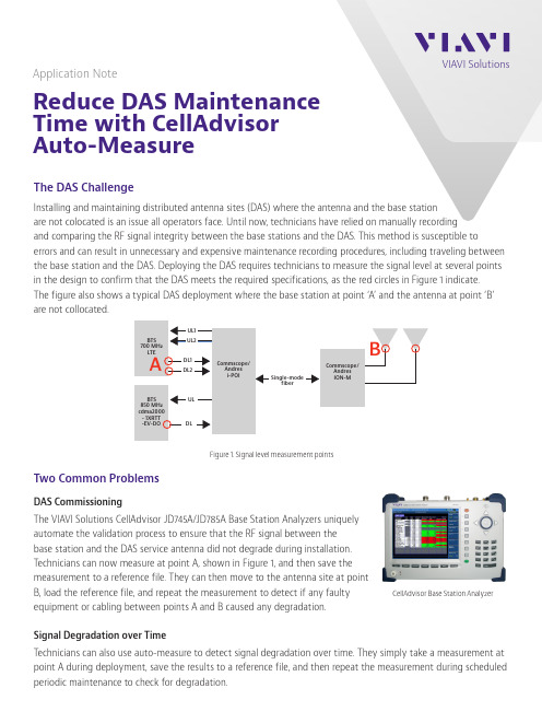
Application NoteReduce DAS Maintenance Time with CellAdvisor Auto-MeasureThe DAS ChallengeInstalling and maintaining distributed antenna sites (DAS) where the antenna and the base stationare not colocated is an issue all operators face. Until now, technicians have relied on manually recording and comparing the RF signal integrity between the base stations and the DAS. This method is susceptible toerrors and can result in unnecessary and expensive maintenance recording procedures, including traveling between the base station and the DAS. Deploying the DAS requires technicians to measure the signal level at several points in the design to confirm that the DAS meets the required specifications, as the red circles in Figure 1 indicate. The figure also shows a typical DAS deployment where the base station at point ‘A’ and the antenna at point ‘B’ are not collocated.Two Common ProblemsDAS CommissioningThe VIAVI Solutions CellAdvisor JD745A/JD785A Base Station Analyzers uniquelyautomate the validation process to ensure that the RF signal between thebase station and the DAS service antenna did not degrade during installation.T echnicians can now measure at point A, shown in Figure 1, and then save themeasurement to a reference file. They can then move to the antenna site at pointB, load the reference file, and repeat the measurement to detect if any faultyequipment or cabling between points A and B caused any degradation.Signal Degradation over TimeT echnicians can also use auto-measure to detect signal degradation over time. They simply take a measurement at point A during deployment, save the results to a reference file, and then repeat the measurement during scheduled periodic maintenance to check for degradation.CellAdvisor Base Station AnalyzerFigure 1. Signal level measurement points© 2021 VIAVI Solutions Inc. Product specifications and descriptions in this document are subject to change without notice.Patented as described at /patents celladvisor-automeasure-an-cpo-nse-ae 30175847 900 0314C ontact Us +1 844 GO VIAVI (+1 844 468 4284)To reach the VIAVI office nearest you, visit /contact VIAVI Solutions The Optimal DAS Testing SolutionVIAVI CellAdvisor JD745A/JD785A Base Station Analysers automate and guide users in measuring DAS, speeding up the deployment and testing process. As Figure 2 shows, the CellAdvisor guides technicians as they connect to point A and make a reference measurement, which is saved as a gold-standard reference file. T aking subsequent measurements at point A can help to detect degradation over time. Measurements taken at point B can help to detect issues between the base station and the antenna. Both measurement methods automatically compare results against the reference file to instantly alert users of any degradation.Instant Result AnalysisIn Auto-Measure mode, VIAVI CellAdvisor JD745A/JD785A Base Station Analyzers automaticallymeasure and display the saved reference values,the new measurement, the difference betweenpoints A and B, and a percentage difference forall parameters. User-configured limits instantlyalert technicians to problems, which eliminatesmisinterpreting results and saves significanttime, and it empowers them to decide whenmaintenance is really necessary. Also, test resultscan be saved in .CSV file format for furtheranalysis or report generation.For more information about DAS Auto-Measureor to request a demonstration, contactyour VIAVI account manager or visit www./go/mobile.Figure 2. Automated measurements and guiding users speedsdeployments and testingPoint A Point BFigure 3. Auto-Measure results。
Vicor设计指南和应用手册(CHINESE)

安装选择 表面安装插座系统(SurfMate) 穿孔插座安装系统(InMate)
技术术语汇编
节数 1 2 3 4 5 6页数 2-4 5 - 11 12 - 17 18 - 19 20 - 24 25 - 30
7
31 - 35
8
36 - 40
9
41 - 47
初级控制集成电路
次级控制集成电路
图 1-3 ─ 全型、小型、微型模块的功率处理和控制基本原理(* 微型系列没有 +/- SENSE 引脚)
第4页
(852)2956-1782 vicorhk@
Rev.4.0
设计指南和应用手册
全型、小型和微型系列 DC-DC 转换器及配件模块
10
48 - 52
11
53 - 55
12
56 - 61
13
62 - 66
14
67 - 71
15
72 - 75
16
76 - 79
17
80 - 87
(852)2956-1782 vicorhk@
Rev.4.0 第1页
1. 高密度 DC-DC 转换器技术
设计指南和应用手册
元件数目减少自然提高产品可靠性及降低成本,令模块 内多出来的空间,可以放置电磁和开关元件,集中处理
功率转换,意味着模块的功率转换性能可以做得更卓 越。
如有需要,可用电阻器调整输出电压高低。Vicor DC-DC 转换器模块有六种引脚类型、三种基板选择,及 齐备的数据表和不同的测试报告。模块的操作温度范围 在 -55℃ 到 100℃ 之间,并分成五个产品级别 — E、 C、T、H 和 M。
ADS 使用例程 说明书

ADS使用例程前言:ADS是一个开发ARM很好的环境,同样周立功单片机()推出的EasyARM2104实验套件也是学习ARM相当超值的入门工具。
由于配套实验书上对于如何做第一个实验方面给出的指导具体步骤不够清晰,新手一般都要摸索一阵子,所以本人写了如下一个ADS的使用例程,演示一个最简单的程序的运行范例。
另外,ADS是一个功能很强大的ARM开发软件,本人的水平也依然停留在初学的层次上,很多深层次的使用问题,设置参数问题需要大家一起仔细阅读英文的pdf使用说明,这里只是希望这篇文档能起到抛砖引玉的作用,把大家领进门。
花了3天时间写出的本文,肯定存在不少错误,加上本人也是新手,所以如果发现文中有错误希望大家指出。
我的e-mail:masashinakayama@注意:本例程要用程序控制周立功EasyARM2104上的LED1,完成该LED1亮暗闪烁。
首先我们假设ADS已经安装完毕(因为涉及版权问题,周公的配套光盘不含ADS软件。
请初学者各显神通,获得该软件)。
本例程使用的是ADS1.2 。
EesyJTAG驱动已经安装。
没安装的请仔细阅读周公配套光盘easyarm_drive\readme.txt安装过程。
EasyARM实验板上JP8 LED1跳线已经短接。
其余跳线设置正确。
(1)建立一个新的项目运行ADS的CodeWarrior IDE,点击File->New,弹出New对话框(如图1)图1 ADS新建工程对话框选择要建立的项目模板,初学者建议选择ARM Executable Image,建立一个ARM指令的项目。
ARM Executable Image 由ARM指令代码生成ELF格式的映像文件Thumb ARM Interworking Image 由ARM指令和Thumb指令混合代码生成ELF格式的映像文件Thumb Execuable Image 由Thumb指令代码生成的ELF格式的映像文件其余选项请参考ADS使用手册在Location项中设置项目的存放目录,并在Project name 项中输入新建项目的名称(本例取名ex_led),然后确定。
CVO STYLE REAR FENDER KITS说明书
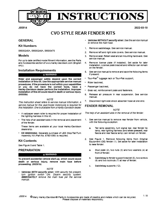
J059142022-03-10CVO STYLE REAR FENDER KITSGENERAL Kit Numbers59500245A,59500246A,59500470ModelsFor up to date certified model fitment information,see the Parts and Accessories section of (English only).Installation RequirementsWARNINGRider and passenger safety depend upon the correct installation of this e the appropriate service manual procedures.If the procedure is not within your capabilities or you do not have the correct tools,have a Harley-Davidson dealer perform the installation.Improper installation of this kit could result in death or serious injury.(00333b)NOTEThis instruction sheet refers to service manual information.A service manual for this year/model motorcycle is required for this installation.One is available from a Harley-Davidson dealer.•A wallpaper seam roller is required for proper installation of the lighting harness in this kit.•The help of an assistant aids in the removal and placement of the fender.These items are available at your local Harley-Davidson dealership.•Kit 59500246A:Separate purchase of LED Stop/Tail/Turn Assembly Kit (Part No.67801090)is required.Kit ContentsSee Figure 5and Table 1.PREPARATIONWARNINGTo prevent accidental vehicle start-up,which could cause death or serious injury,remove main fuse before proceeding.(00251b)NOTE•Vehicles WITH security siren:With security fob present,turn ignition switch ON.Disarm security system.IMMEDIATELY remove the main fuse per the service manual.•Vehicles WITHOUT security siren:See the service manual to remove the main fuse.1.Remove saddlebags.See service manual.2.Remove left and right side covers.See service manual.3.Remove seat.Retain seat and all mounting hardware.See service manual.4.Remove license plate (if installed).Set aside for later installation.License plate bracket and reflector can remain on the fender.5.See service manual to remove and save the following items if present:•Tour-Pak ®luggage rack or Tour-Pak support,•Rider backrest,•Passenger backrest,•Grab rail,reinforcement plate and fasteners.6.Release air pressure in rear suspension.See service manual.7.Disconnect right side shock absorber hose at one end.FENDER REMOVALNOTEThe help of an assistant aids in the removal of the fender.1.See service manual to remove rear fender from vehicle,with the following exception:a.Tail lamp assembly,turn signal bar,rear fender tip lamp,rear lighting harness (and when present ,rear fascia and rear fascia lamp)can remain on fender.2.See Figure 1.Remove following items from Original Equipment (OE)fender (1).Set aside for later installation to new fender:a.Stud plate (2),two nuts (3)and two washers (4)at front of fender.b.Saddlebag to fender support bracket (5),two screws (6)and two locknuts (7)at rear of fender.c.Saddlebag supports (12).1/8Many Harley-Davidson®Parts &Accessories are made of plastics and metals which can be recycled.J05914Please dispose of materials responsibly.that damage painted surfaces.NOTEThe two branches of rear lighting harness without adhesiveconduit remain outside the fender.2.Get stud plate(2)removed from OE fender.3.Position plate to inside front of fender with channelpositioned nearest wire hole.4.Loosely assemble plate to fender with the OE nuts(3)andwashers(4).Do not fully tighten.5.Install rear harness(5)to underside of fender:a.Feed main body of harness(with adhesive conduit),from outside,through hole(9)in front of fender.2/8J05914J059143/8License Lamp InstallationNOTESome license lamps have a tab(see Figure3inset,Item18) that prevents installation.Remove tab before proceeding.1.See Figure3.Assemble license lamp(2)and cover(4)tolicense plate bracket(1).2.Tighten screws(5).T orque:6.4–7.8N·m(57–69in-lbs)Hex socket head screw3.Get stud plate(11)and two foam tape pads(12)from kit.4.Remove liner from adhesive backing on one side of onepad.5.Carefully position pad to a flange of stud plate,on sideopposite of nuts,and press firmly into place.6.Repeat with second pad on remaining flange.7.Remove liner from exposed side of pads.8.Feed lamp wires(3)through license bracket(1)and hole(10)in fender(9).9.Hold stud plate(11)in place on underside of fender.10.Secure license plate bracket(1)to stud plate with washers(8)and screws(5).11.Tighten screws securely.12.Insert license lamp wires into two-way socket housing(14).See service manual.13.Secure with secondary lock(15).14.Plug two-way pin housing on rear harness into license lampsocket[45B].15.Install license lamp connector cover(16).16.Secure with a flange nut(17).Tighten.Torque:3.4–5.1N·m(30–45in-lbs)Hex flange nut17.Secure wire harness with clip on inside of fender.18.Install to reflector and bracket assembly(7)as shown. Center Stop/Tail Lamp Installation(If Equipped)Install new center stop/tail lamp from kit(59500245A).See service manual.Rear Fascia Installation1.See Figure1.Install a new fender mounting boss(11),from inside,through one of four holes in sides of fender.2.Place a washer(10)onto threads of boss and fasten witha nut(9).Tighten.Torque:20.3–27.1N·m(15–20ft-lbs)Hex nut3.Repeat for remaining three holes.4.See Figure4.Remove liner from adhesive backing of44.5x19x1.6mm(x in)rubber pad(2).5.Position pad to center of fascia(1),just below the slot asshown,and press firmly into place.6.Position fascia under rear edge of fender.7.Align three holes on each side of fascia with mating holesin the fender.8.Insert three studs of a stud plate(3),from beneath fender,through fender holes and fascia on one side.9.Install a fascia support bracket(stiffener plate,4)overstuds.10.Loosely install three flange nuts(5)onto stud threads.NOTE•U.S.models only:Fascia-mounted LED lamps are identical.•International models:Fascia-mounted LED lamps are bel on back of left side lamp is marked"LEFT".Right side lamp is marked"RIGHT".Remove blue film from lens faces before lamps are installed in fascia.11.Loosely fasten other side of fascia with remaining studplate,support bracket and flange nuts.12.Alternately tighten each flange nut.Torque:3.4–5.1N·m(30–45in-lbs)Hex flange nut13.Install a rear fascia lamp(6)into correct-side opening infascia from behind.14.Fasten with three black#10TORX®screws(7).15.Alternately tighten each screw.Torque:1.6–2.1N·m(14–18in-lbs)TORX pan head screw 16.Repeat for remaining fascia lamp.4/8J05914Figure4.Rear Fascia Installation Antenna Relocation on FLHX and FLHTRX Models1.See Figure5.Disconnect antenna cable from antenna baseassembly.2.Unscrew antenna mast from antenna base.3.Remove lower locknut.4.Remove antenna base from mounting bracket.5.Remove two screws and lockwashers retaining the antennamounting bracket.6.Remove and discard any cable straps securing antennacable to fender support and saddlebag rear support brackets.7.See Figure5.Position new antenna bracket(30)nearfender supports and fasten bracket to fender supports:a.Assemble thin washer(37)to screw threads.b.Install screws(36)and washers(37)through antennabracket from rear.c.See Figure5.Slide spacers(34and35)onto threadsthat are extending through bracket.Note spacerlengths.d.Align and fasten this bracket and fastener assemblyto fender support.Tighten.Torque:20.3–27.1N·m(15–20ft-lbs)Fastenerassembly8.Install tooth lockwasher(32)from kit onto larger threadsof antenna base(31)under hex nut(33).9.Insert antenna base through hole in antenna mountingbracket.10.Install second hex nut(33)onto threads of antenna base.11.Place a wrench on upper nut and tighten lower nut.Torque:8N·m(6ft-lbs)Lower nut12.Plug antenna cable connector into antenna base.13.Tighten knurled nut to secure connector to antenna base.14.Allow slack in cable at antenna base to avoid kinking orbinding at connection.15.Fasten antenna cable to fender support bar with a cablestrap.e a second cable strap to tie antenna cable(FLHXmodels,excess rear fascia lamp wires)to frame rail,near suspension air lines,underneath painted cover.17.DO NOT tie cable to air lines.18.Thread antenna mast assembly securely onto antennabase(31).FENDER INSTALLATIONNOTE•The help of an assistant aids in the placement of the fender onto the motorcycle.•Protect lower edges of fascia beneath tail lamps with tape to prevent mufflers damaging the paint during fender installation.1.Carefully roll forward the new fender into position betweenrear frame rails.2.See Figure5.Get four5/16-18x25.4mm(1in)long fendermounting screws(5)from kit.3.Loosely install a screw through rear frame rail into rearmostfender mounting boss on each side.4.Align front mounting holes.5.Loosely install remaining screws through frame rails intoforward fender mounting boss on each side.6.Get two5/16-18x25.4mm(1in)long fender mountingscrews and flanged locknuts saved earlier.J059145/87.Install screws,from the front,through saddlebag supportlower rear mounting holes and saddlebag to fender support bracket.8.Loosely install flanged locknuts onto screw threads.NOTEFLHX Models:The electrical caddy must be loosened to allow the harness connector to fit through.9.Route harness leg with gray four-way connector betweenfront of fender and left side fender support.10.Plug connector[18]into left side fascia lamp.11.Route harness leg with black four-way connector betweenfront of fender and right side fender support.12.Plug connector[19]into right side fascia lamp.13.Alternately tighten four fender mounting screws.Torque:20.3–27.1N·m(15–20ft-lbs)TORX pan head screw 14.Install rear shock absorber air hose to air valve assemblyon left side.15.See Figure1.Install saddlebag supports(12).16.Loosely install passenger grab strap.17.See e a clip(7)from kit to fasten a harnessleg to clip slot on underside of each saddlebag support.COMPLETIONNOTETo prevent possible damage to sound system,verify that ignition switch is OFF before installing main fuse.To prevent accidental vehicle start-up,which could cause death or serious injury,remove main fuse before proceeding.(00251b)1.Install main fuse.See service manual.2.Verify that all lights are working properly before putting thevehicle in service.6/8J05914Figure5.Service Parts,FL Touring CVO-Style Rear Fender KitsJ059147/8SERVICE PARTSTable 1.Service PartsPart Number Description (Quantity)Item 60463-09A 60472-09A Fender,rear (Prime paint,no center tail lamp opening)(kit 59500246A)Fender,rear (Prime paint,with center tail lamp opening)(kit 59500245A)159786-01Boss,fender mounting (4)259788-01Washer,fender mounting (4)37880Hex nut,1/2-13(4)43684Screw,pan head TORX,self-tapping,5/16-18x 25.4mm (1in)long (4)511100068Cushion,saddlebag support (2)669200313Clip (6)(kit 59500246A)Clip (2)(kits 59500245A,59500470)711891Spacer,rubber,adhesive-backed,44.5x 19x 1.6mm (x in)859500107Fascia,rear fender (unpainted)(kits 59500246A,59500245A)959500018Stud plate (2)1067900185Fascia support bracket (2)117499Large flange nut,1/4-20(7)1267800201LED Stop/Tail/Turn Assembly,Red Lens (kit 59500245A or 59500246A)1367800203LED Stop/Tail/Turn Assembly,Amber Lens,Right (kit 59500470)67800204LED Stop/tail/Turn Assembly,Amber Lens,Left (kit 59500470)3152Screw,pan head TORX,black,#10x 12.7mm (0.5in)long (6)1467900233Bracket,license plate1560934-10Cover,license light (unpainted)(kits 59500246A,59500245A)16940Screw,1/4-20x 19mm (0.75in)(4)1760920-09Light,license plate1874112-98BK Socket housing,2-way,black 1974152-98Secondary lock2067900232Gasket,upper license plate 2159840-09Stud plate2260916-09Connector cover2311100008Foam pad,adhesive-backed,license plate bracket (2)2467900244Reflector and bracket assembly 256119Washer (2)2610102Clip,adhesive-backed (2)286920072069200719Harness,rear lighting (kit 59500246A)Harness,rear lighting (kits 59500245A,59500470)2976555-09Antenna bracket,rear3076335-87Antenna base assembly (includes items 32-33)317129•Lock washer3276259-86•Nut (2)3312400091Spacer,antenna,front 3412400092Spacer,antenna,rear353148Screw,button head TORX,5/16-18x 41.3mm (1.62in)long,Grade 8(2)366702Flat washer (2)37Items used in kits 59500245A and 59500470only:68142-04Light assembly,tail lamp (includes items 39-44)3868558-03•Lens,tail lamp (includes item 40)3968026-99•.....Screw,tail lamp (2)4069187-03A •Bulb and socket assembly,tail lamp (includes item 42-44)4168167-04•.....Bulb,tail lamp,wedge mount 4273154-96BK •.....Socket housing,four-way 4373191-96•.....Socket terminal,#16-20AWG (3)4468066-99A Tail lamp base assembly (includes items 46-47)4568296-99A •.....Tail lamp base (chrome)4668830-99A •.....Circuit board and cover473022A Screw,socket head,1/4-20x 16mm (⅝in)long 487964J-nut49Kits 59500245A,59500470A,C Kit 59500246AB8/8J05914。
Bohlin ADS CVO

Bohlin ADS CVO-100型流变仪不清楚的问题如下:(1)测量的标准方法,特别是测试过程中的注意事项、数据解释和误差来源分析等。
(2)如何用标准液对流变仪进行正确的标定?采用original binder 模式还是cannon standard 模式?(3)如何进行频率扫描、振幅扫描、等变速率温度扫描及时间扫描等操作,请演示(4)进行了频率扫描、温度扫描后,如果进行时温叠加,得出主曲线?有没有相应的软件?(5)在作试验时,如何进行线性分析?如何利用SHRP linear analysis、model fit 和thiotopic analysis进行线性分析?沥青在SHRP分析时,针对不同老化程度的沥青,采用不同的应变控制,原因就是线弹性,如何在各个阶段进行线弹性分析?(6)怎么做蠕变试验?做蠕变恢复试验步骤及其相关参数的意义如下:①creep:a. shear stress剪应力:根据试验和规范要求,进行设置或改变参数;b. creep time(s) 蠕变时间:指做一个蠕变需要的总的时间;c. default sampling中的采样取模式,可采用linear(线性);log(对数);peseudo-log(半对数,默认设置)。
主要是画图时的区间,region times与creep times 相同;②recovery:a. 如果做恢复试验,则选中perform recovery;b. recovery times (恢复时间):指做一个恢复的总的时间间隔;c. default sampling中的采样模式,意义与creep 一样,而且两者最好一致。
③temperature:注意设置temperature equilibrium time(s),此值不仅是第一次蠕变试验的保温时间,也是以后各次蠕变之间的间隔时间。
④上面的设置是做一次的试验情况,如何设置重复上述试验过程?只需在No. of Repeats 下的矩形框中填入设置值即可。
- 1、下载文档前请自行甄别文档内容的完整性,平台不提供额外的编辑、内容补充、找答案等附加服务。
- 2、"仅部分预览"的文档,不可在线预览部分如存在完整性等问题,可反馈申请退款(可完整预览的文档不适用该条件!)。
- 3、如文档侵犯您的权益,请联系客服反馈,我们会尽快为您处理(人工客服工作时间:9:00-18:30)。
CVO/ADS使用说明版本1.0到6.0适用/2001,1,4简介本手册简要描述如何用CVO-ADS做沥青测量,需要更多的资料,可查阅SHRP相关文件及AASHTO和ASTM规范。
本说明讨论下列内容:ü软件使用ü间隙设置ü测量系统安装ü温度确认和校正ü试样准备ü标准油的性能确认CVOADS 是 一套完整的分析功能超过AASHTO TP5测试协议要求的先进流变分析系统。
用户对这些特性感兴趣,可参阅详细讨论CVO特性的用户手册。
CVO配备有专利恒温室,可用于5-85°C范围的试样测试。
软件:软件提供一组标准的测试模板实现符合AASHTO标准的原样沥青(OB)、旋转薄膜烘箱残留沥青(RTFO)和压力老化后的沥青的分级。
有几种不同的方法执行标准沥青测试及各种方法的对照。
自动操作是理想的测试方式,设定初始温度、测试间隙对零,在振荡软件手动温度设置框键入测试温度。
部分用户喜欢使用手动操作设置测试温度。
无论使用手动或自动方法,正确的测试系统可在软件中自动选择(如:25毫米平行盘、1毫米间隙用于原样沥青和旋转薄模烘箱残留沥青测试,8毫米平行盘、2毫米间隙用于PAV老化后的沥青)手动操作:可以通过选择File》Open从振荡菜单中选择测试协议。
从RheologyData (*.dow)和Parameters(*.pow)中改变选项Files of Type(类型文件)。
标准测试放在BOHLIN子目录PG测试中。
打开测试参数文件,点击绿色箭头起动测试。
每个参数文件已预置了正确的测试系统(25mm平行盘、1mm间隙用于原样沥青和旋转薄模烘箱残留沥青;8mm平行盘、2mm间隙用于PAV后沥青。
) 自动操作:标准协议可以安装在BOHLIN软件用户定义测试窗口,只需点击相应的标题即可启动测试。
这样做的优点是只需点击需要的测试,测试就可立即启动。
软件将控制仪器到参数文件中选定的测试温度、等待AASHTO协议规定的时间,执行分级确认。
确认协议由OB、RTFO、PAV等字母后加确认温度来识别。
如,PG64确认是在温度为64°C做测试。
相应的文件是OB64。
一组独立的协议用于确定未知的原样、RTFO和PAV沥青试样的等级。
在本测试中,OB和RTFO分级的初始测试温度是58°C。
软件将在58°C起始温度开始确认测试。
如果试样通过该温度确认测试,将增加6°C再重复确认试验,直到试样测试失败。
对于原样沥青G*/ sin(.)>=1.00 kPa 为通过,对于RTFO沥青 G*/sin(ä)>=2.20 kPa 为通过,否则为测试失败。
本测试的缺省起始测试温度设定为 58°C. 可以通过软件中的温度图标,选择手动温度、然后键入所需的起始测试温度,采用File》Save保存修改。
PAV分级测试中,初始测试温度设定为 22°C.软件将从22°C开始执行确认测试。
如果试样在该温度点通过确认测试,则减3°C,重复做确认测试直到确认测试失败,即G*sin(.)<=5000KPa。
本测试缺省启动温度为58。
该缺省值可以通过电击软件中的温度图标、选择手动温度、然后键入所需温度改变。
存储该改变,选择File, Save.Linearity(线性)-本测试执行TP5-98规范附录A1沥青线性测试。
该协议应力从25Pa到2000Pa分段增加,比较2%应变处和12%应变处得到的G*,如果12%处的G*小于2%处的G*的90%,材料视为非线性。
详见规范附录。
安装测量系统ADS试样测试中配有两上、下个测量系统。
原样沥青和RTFO沥青使用25mm平行盘1mm间隙;PAV试样测试使用8mm平行盘2mm间隙。
选定的测量系统需预先装入流变仪。
放置下测量系统到集水盘上、装上锁紧圈。
测量系统的锁紧圈应自由旋下,如果感到有阻力,重新插入测量系统,不要过度用力。
转动卡盘,滑动空气轴承锁向左锁住卡盘。
见图11图11-卡盘锁住顺时针旋转放松卡盘(从下向上看),放入集水盘到上测量系统,插入到卡盘内。
锁紧卡盘。
将白色塑料集水盘放置到位,水可覆盖上下盘。
由于卡盘上面开口尺寸限制,在安装25mm上测量系统盘时,必须先放入集水盘再安装锁紧上测量系统盘。
使用8mm小测试盘,可以在锁紧上测量盘后再装集水盘。
当装上测量盘:检查保证空气轴承轴在锁紧位置,插入上测量盘轴,仔细从底面扶住轴将其平滑放入卡盘直到轴完全插入、拧紧卡盘。
图4.安装上测试盘安装完成后,放松空气轴承卡盘,用手轻轻转动轴保证自由活动。
见图1。
图1-打开卡盘设定测试盘间隙对于精确的测量,上下测量盘之间正确的间隙设定是非常重要的。
间隙不正确会导致结果错误。
在流变仪中插入上下测量盘。
放入卡盘(见图11)按下CVO前面板上ZERO键。
在CVO出现动作前,需要按住并保持定点时间。
CVO现在自动寻找零位(上下测量盘刚接触位置),等待OK灯亮。
见图2。
按下UP按钮提升上测量盘到加入试样位置。
图2-发现零位显示装入试样加入试样时,试样的数量要合适。
按试样准备章节描述准备试样。
原样沥青和RTFO沥青使用25mm测量盘,初始间隙为1.05mm。
去除过多的试样,然后减少间隙到最终间隙1mm。
对于PAV试样,使用8mm测量盘,初始间隙为2.05mm,修边去除多余试样后设定间隙到2mm。
加试样时,首先设定Gap间隙为1.05mm。
按Gap键,然后按DOWN或UP按钮到达1.05mm的间隙,再按下Gap按钮锁住间隙设定。
放置试样到上下测量盘之间,按下向下箭头键,CVO-ADS下降到1。
05mm的初始设定间隙。
修剪去除过多的测试材料,使用至少4mm宽的工具。
下面是一些有益建议:•制作或购买好的修剪工具。
修剪工具•当在高温范围修剪试样时,工具无须加热,除非试样是改性沥青。
如果需要加热工具,加热到可以切下材料即可。
•当在中温范围加热修剪改性沥青或PAV沥青工具时,过热的工具可能引起太多的材料从平行盘之间流出。
加热时当心,避免损坏试样。
•相反,未加热的工具可能使材料从平行盘间拉出。
加热到合适的温度,需要有一定经验。
•当感觉材料修剪完成,稍加热工具,清除测量盘边流出材料,直到工具不再有残留材料。
注:加热修剪工具要避免工具太热。
试样现在可调整到1mm(对于25mm测试盘)或2mm(对于8mm测试盘)。
预置间隙调整到1mm,然后按向下箭头键,达到测试间隙。
放下并缩紧白色塑料集水盘,使水覆盖上下测量盘。
将卡盘拉向右边,放开转轴锁(见图9)PAV试样放置过程与此类似,只是初始测量间隙为2.05mm,最终间隙设定为2.00mm。
平行盘在设定间隙后要预热到45oC左右,以保证沥青和测试盘之间粘结牢靠。
注:•直接加流体沥青到下测试盘上。
•移开下测试盘加热,用手放入试样,保证试样与8mm测试盘接触。
再装入仪器。
•目的是为了粘结牢固。
试样加入摘要:•测试PAV老化试样,预热测试盘到45oC。
•增加间隙,流有足够空间。
•到入试样到下测试盘或使用硅胶模制作试样。
•放低上测试盘,夹紧试样。
•修剪测试盘边缘流出的材料。
•消除额外的用于修剪多余测试材料的0。
05mm间隙。
•放下并卡紧白色塑料集水盘。
•去除转轴锁。
试样准备加热沥青试样到可以流动,试样应放入135oC的烘箱内。
对于改性沥青,可能需要更高的温度。
不要超过163oC。
当沥青可以流动时,搅动沥青保证材料均匀、无气泡。
试样可以按下面两种方法之一来准备:•直接倾到材料到测量盘。
规范指明可以直接倾注沥青到可移动盘上。
•倾注到硅胶模上,冷却后转送到测试盘上。
到入试样后,检查气泡和试样是否均匀。
对于大多数材料,室温下一分钟冷却即可脱模。
试样可以拉下模具角检查。
见图12、13。
如果试样不易脱模,等多一、两分钟。
图12。
使用硅胶模到试样图 13 检查脱模情况从模具上取下材料,放置到测试盘的中心,见图14。
14图温度确认/校正本节描述确认/校正流变仪的步骤。
试样温度测量采用PT100,直接放置到浸入水槽中的下测试盘下面。
实际试样温度可能稍有不同,可以通过进行温度控制水浴循环器校正来补偿。
小幅度的调整即可使试样达到合适的温度。
如果要调整20-30度,或者不可能保持温度稳定,要联系厂家做进一步的校正。
在做校正前,请阅读故障查寻章节的内容。
1.设定流变仪到测试温度或期望的测试范围的中段。
2.安装上与需做测试相对应的测试盘。
3.确认/校正温度,需要温度计和万用表。
(Cannon温度计和福绿克万用表或兼容的测量仪器)在安装到CVO前,需要测量温度计厚度,然后在间隙设置中键入温度计厚度。
4.在温度计上涂上油保证良好的热传导。
乳胶温度计不防水,如果水进入胶片,可能出现短路。
5.通过白色的塑料盖,温度计的导线穿出。
导线从盖底到顶部拉出,25mm的圆盘温度计靠近测量盘(图5)6.将温度计与上下测量盘对中,按向下箭头键,直到温度计在上下测量盘之间刚好夹住。
图5 温度计导线 图6 温度计放置位置警告:不要压缩放置于上下测量盘中的温度计。
使用时要极其小心。
需要弯曲温度计盘引出导线10mm左右,防止导线折断。
不要在盘上弯曲。
7.放低并夹紧白色集水盘,水应从集水盘上面流出。
注:如果没有放到位,可能需要线夹。
(图7)8.连接温度计端部线夹到福绿克万用表。
•红-- VL2•黑 ---- COM9.让水浴温度稳定。
(约30分钟,或直到温度计读数稳定)10.将万用表设定到欧姆档,读取电阻数值(单位为千欧)。
数据读取后,应关闭万用表。
注:对温度计长时间通电可能导致温度计本身温度上升,影响温度测量精度。
11.根据测量的电阻,用温度计随机校正文件给出的公式计算温度注:有一个EXCEL的计算软件TEMPCAL.xls可以方便用于计算测量温度(可从BOHLINUSA网址下载)。
下图是TEMPCAL.XLS使用例子。
•万用表显示值 22.70 kΩ按下图键入•E4单元得出对应的计算温度•转换到EXCEL键入到输入框中的公式如下:=1000/(B1O+(DlO*LN(E2))+(F10*LN(E2)^3))-273•在E6单元键入目标温度。
•E8单元的公式是E6-E4,结果是水浴循环器需要键入的补偿值。
• a0,a 1, 和 a2的数值可在校正证明上查得,每个温度计都会有所不同。
故障诊断1.温度控制差/水从集水盘顶部溢出。
•需要最大的水流量。
•检查水槽底部绿色过滤器,在校正/确认温度前改变或调节水流速度。
注:这可能影响实际的水浴温度。
过滤器应清洁无脏物。
过滤器可能需要更换。
使用入口阀,调节进入流变仪的流体流速。
入口阀在连接到流变仪的管路上。
用于调节流体流动速度,保证试样浸入到流体中,而又不至于溢流。
