015 TC操作手册之---指针与内存操作
c51指针用法
c51指针用法
C51是一种常用的单片机,使用指针可以更灵活地操作内存和外设。
在C51中,指针可以用于访问和操作内存中的数据,也可以用于操作外设寄存器。
首先,我们可以使用指针来访问和操作内存中的数据。
在C51中,内存被分为不同的存储区域,如代码区、数据区和堆栈区。
通过使用指针,我们可以直接访问和修改这些存储区域中的数据。
例如,我们可以使用指针来读取和修改数组中的元素,而不需要使用数组索引。
这种方法可以提高程序的执行效率。
其次,指针还可以用于操作外设寄存器。
在单片机编程中,外设寄存器用于控制和配置外部设备,如GPIO(通用输入输出)、定时器和串口等。
通过使用指针,我们可以直接访问和修改这些寄存器的值,从而控制外部设备的行为。
例如,我们可以使用指针来设置GPIO引脚的状态,或者配置定时器的工作模式。
除了访问和操作内存和外设寄存器,指针还可以用于动态内存分配和数据结构的操作。
在C51中,我们可以使用指针来动态分配内存,并在运行时根据需要分配和释放内存。
这种灵活的内存管理方式可以提高程序的效率和灵活性。
此外,指针还可以用于创建和操作复杂的数据结构,如链表和树等。
通过使用指针,我们可以方便地插入、删除
和修改数据结构中的元素。
总之,C51中的指针用法非常重要,可以帮助我们更灵活地操作内存和外设。
通过使用指针,我们可以提高程序的执行效率,实现动态内存分配,以及创建和操作复杂的数据结构。
因此,熟练掌握C51指针的用法对于单片机编程非常重要。
pride 内存数据库 使用说明

PRIDE:A Data Abstraction Layer for Large-Scale2-tier Sensor NetworksWoochul Kang University of Virginia Email:wk5f@Sang H.SonUniversity of VirginiaEmail:son@John A.StankovicUniversity of VirginiaEmail:stankovic@Abstract—It is a challenging task to provide timely access to global data from sensors in large-scale sensor network applica-tions.Current data storage architectures for sensor networks have to make trade-offs between timeliness and scalability. PRIDE is a data abstraction layer for2-tier sensor networks, which enables timely access to global data from the sensor tier to all participating nodes in the upper storage tier.The design of PRIDE is heavily influenced by collaborative real-time ap-plications such as search-and-rescue tasks for high-rise building fires,in which multiple devices have to collect and manage data streams from massive sensors in cooperation.PRIDE achieves scalability,timeliness,andflexibility simultaneously for such applications by combining a model-driven full replication scheme and adaptive data quality control mechanism in the storage-tier. We show the viability of the proposed solution by implementing and evaluating it on a large-scale2-tier sensor network testbed. The experiment results show that the model-driven replication provides the benefit of full replication in a scalable and controlled manner.I.I NTRODUCTIONRecent advances in sensor technology and wireless connec-tivity have paved the way for next generation real-time appli-cations that are highly data-driven,where data represent real-world status.For many of these applications,data streams from sensors are managed and processed by application-specific devices such as PDAs,base stations,and micro servers.Fur-ther,as sensors are deployed in increasing numbers,a single device cannot handle all sensor streams due to their scale and geographic distribution.Often,a group of such devices need to collaborate to achieve a common goal.For instance,during a search-and-rescue task for a buildingfire,while PDAs carried byfirefighters collect data from nearby sensors to check the dynamic status of the building,a team of suchfirefighters have to collaborate by sharing their locally collected real-time data with peerfirefighters since each individualfirefighter has only limited information from nearby sensors[1].The building-wide situation assessment requires fusioning data from all(or most of)firefighters.As this scenario shows,lots of future real-time applications will interact with physical world via large numbers of un-derlying sensors.The data from the sensors will be managed by distributed devices in cooperation.These devices can be either stationary(e.g.,base stations)or mobile(e.g.,PDAs and smartphones).Sharing data,and allowing timely access to global data for each participating entity is mandatory for suc-cessful collaboration in such distributed real-time applications.Data replication[2]has been a key technique that enables each participating entity to share data and obtain an understanding of the global status without the need for a central server. In particular,for distributed real-time applications,the data replication is essential to avoid unpredictable communication delays[3][4].PRIDE(Predictive Replication In Distributed Embedded systems)is a data abstraction layer for devices performing collaborative real-time tasks.It is linked to an application(s) at each device,and provides transparent and timely access to global data from underlying sensors via a scalable and robust replication mechanism.Each participating device can transparently access the global data from all underlying sen-sors without noticing whether it is from local sensors,or from remote sensors,which are covered by peer devices. Since global data from all underlying sensors are available at each device,queries on global spatio-temporal data can be efficiently answered using local data access methods,e.g.,B+ tree indexing,without further communication.Further,since all participating devices share the same set of data,any of them can be a primary device that manages a sensor.For example,when entities(either sensor nodes or devices)are mobile,any device that is close to a sensor node can be a primary storage node of the sensor node.Thisflexibility via decoupling the data source tier(sensors)from the storage tier is very important if we consider the highly dynamic nature of wireless sensor network applications.Even with these advantages,the high overhead of repli-cation limits its applicability[2].Since potentially a vast number of sensor streams are involved,it is not generally possible to propagate every sensor measurement to all devices in the system.Moreover,the data arrival rate can be high and unpredictable.During critical situations,the data rates can significantly increase and exceed system capacity.If no corrective action is taken,queues will form and the laten-cies of queries will increase without bound.In the context of centralized systems,several intelligent resource allocation schemes have been proposed to dynamically control the high and unpredictable rate of sensor streams[5][6][7].However, no work has been done in the context of distributed and replicated systems.In this paper,we focus on providing a scalable and robust replication mechanism.The contributions of this paper are: 1)a model-driven scalable replication mechanism,which2significantly reduces the overall communication and computation overheads,2)a global snapshot management scheme for efficientsupport of spatial queries on global data,3)a control-theoretic quality-of-data management algo-rithm for robustness against unpredictable workload changes,and4)the implementation and evaluation of the proposed ap-proach on a real device with realistic workloads.To make the replication scalable,PRIDE provides a model-driven replication scheme,in which the models of sensor streams are replicated to peer storage nodes,instead of data themselves.Once a model for a sensor stream is replicated from a primary storage node of the sensor to peer nodes,the updates from the sensor are propagated to peer nodes only if the prediction from the current model is not accurate enough. Our evaluation in Section5shows that this model-driven approach makes PRIDE highly scalable by significantly re-ducing the communication/computation overheads.Moreover, the Kalmanfilter-based modeling technique in PRIDE is light-weight and highly adaptable because it dynamically adjusts its model parameters at run-time without training.Spatial queries on global data are efficiently supported by taking snapshots from the models periodically.The snapshot is an up-to-date reflection of the monitored situation.Given this fresh snapshot,PRIDE supports a rich set of local data orga-nization mechanisms such as B+tree indexing to efficiently process spatial queries.In PRIDE,the robustness against unpredictable workloads is achieved by dynamically adjusting the precision bounds at each node to maintain a proper level of system load,CPU utilization in particular.The coordination is made among the nodes such that relatively under-loaded nodes synchronize their precision bound with an relatively overloaded node. Using this coordination,we ensure that the congestion at the overloaded node is effectively resolved.To show the viability of the proposed approach,we imple-mented a prototype of PRIDE on a large-scale testbed com-posed of Nokia N810Internet tablets[8],a cluster computer, and a realistic sensor stream generator.We chose Nokia N810 since it represents emerging ubiquitous computing platforms such as PDAs,smartphones,and mobile computers,which will be expected to interact with ubiquitous sensors in the near future.Based on the prototype implementation,we in-vestigated system performance attributes such as communica-tion/computation loads,energy efficiency,and robustness.Our evaluation results demonstrate that PRIDE takes advantage of full replication in an efficient,highly robust and scalable manner.The rest of this paper is organized as follows.Section2 presents the overview of PRIDE.Section3presents the details of the model-driven replication.Section4discusses our pro-totype implemention,and Section5presents our experimental results.We present related work in Section6and conclusions in Section7.II.O VERVIEW OF PRIDEA.System ModelFig.1.A collaborative application on a2-tier sensor network. PRIDE envisions2-tier sensor network systems with a sensor tier and a storage tier as shown in Figure1.The sensor tier consists of a large number of cheap and simple sensors;S={s1,s2,...,s n},where s i is a sensor.Sensors are assumed to be highly constrained in resources,and per-form only primitive functions such as sensing and multi-hop communication without local storage.Sensors stream data or events to a nearest storage node.These sensors can be either stationary or mobile;e.g.,sensors attached to afirefighter are mobile.The storage tier consists of more powerful devices such as PDAs,smartphones,and base stations;D={d1,d2,...,d m}, where d i is a storage node.These devices are relatively resource-rich compared with sensor nodes.However,these devices also have limited resources in terms of processor cycles,memory,power,and bandwidth.Each storage node provides in-network storage for underlying sensors,and stores data from sensors in its vicinity.Each node supports multiple radios;an802.11radio to connect to a wireless mesh network and a802.15.4to communicate with underlying sensors.Each node in this tier can be either stationary(e.g.,base stations), or mobile(e.g.,smartphones and PDAs).The sensor tier and the storage tier have loose coupling; the storage node,which a sensor belongs to,can be changed dynamically without coordination between the two tiers.This loose coupling is required in many sensor network applications if we consider the highly dynamic nature of such systems.For example,the mobility of sensors and storage nodes makes the system design very complex and inflexible if two tiers are tightly coupled;a complex group management and hand-off procedure is required to handle the mobility of entities[9]. Applications at each storage node are linked to the PRIDE layer.Applications issue queries to underlying PRIDE layer either autonomously,or by simply forwarding queries from external users.In the search-and-rescue task example,each storage node serves as both an in-network data storage for nearby sensors and a device to run autonomous real-time applications for the mission;the applications collect data by issuing queries and analyzing the situation to report results to thefirefighter.Afterwards,a node refers to a storage node if it is not explicitly stated.3Fig.2.The architecture of PRIDE(Gray boxes).age ModelIn PRIDE,all nodes in the storage tier are homogeneous in terms of their roles;no asymmetrical function is placed on a sub-group of the nodes.All or part of the nodes in the storage tier form a replication group R to share the data from underlying sensors,where R⊂D.Once a node joins the replication group,updates from its local sensors are propagated to peer nodes;conversely,the node can receive updates from remote sensors via peer nodes.Any storage node,which is receiving updates directly from a sensor,becomes a primary node for the sensor,and it broadcasts the updates from the sensor to peer nodes.However,it should be noted that,as will be shown in Section3,the PRIDE layer at each node performs model-driven replication,instead of replicating sensor data,to make the replication efficient and scalable.PRIDE is characterized by the queries that it supports. PRIDE supports both temporal queries on each individual sensor stream and spatial queries on current global data.Tem-poral queries on sensor s i’s historical data can be answered using the model for s i.An example of temporal query is “What is the value of sensor s i5minutes ago?”For spatial queries,each storage node provides a snapshot on the entire set of underlying sensors(both local and remote sensors.)The snapshot is similar to a view in database ing the snapshot,PRIDE provides traditional data organization and access methods for efficient spatial query processing.The access methods can be applied to any attributes,e.g.,sensor value,sensor ID,and location;therefore,value-based queries can be efficiently supported.Basic operations on the access methods such as insertion,deletion,retrieval,and the iterating cursors are supported.Special operations such as join cursors for join operations are also supported by making indexes to multiple attributes,e.g.,temperature and location attributes. This join operation is required to efficiently support complex spatial queries such as“Return the current temperatures of sensors located at room#4.”III.PRIDE D ATA A BSTRACTION L AYERThe architecture of PRIDE is shown in Figure2.PRIDE consists of three key components:(i)filter&prediction engine,which is responsible for sensor streamfiltering,model update,and broadcasting of updates to peer nodes,(ii)query processor,which handles queries on spatial and temporal data by using a snapshot and temporal models,respectively,and (iii)feedback controller,which determines proper precision bounds of data for scalability and overload protection.A.Filter&Prediction EngineThe goals offilter&prediction engine are tofilter out updates from local sensors using models,and to synchronize models at each storage node.The premise of using models is that the physical phenomena observed by sensors can be captured by models and a large amount of sensor data can be filtered out using the models.In PRIDE,when a sensor Input:update v from sensor s iˆv=prediction from model for s i;1if|ˆv−v|≥δthen2broadcast to peer storage nodes;3update data for s i in the snapshot;4update model m i for s i;5store to cache for later temporal query processing;6else7discard v(or store for logging);8end9Algorithm2:OnUpdateFromPeer.stream s i is covered by PRIDE replication group R,each storage node in R maintains a model m i for s i.Therefore, all storage nodes in R maintain a same set of synchronized models,M={m1,m2,...,m n},for all sensor streams in underlying sensor tier.Each model m i for sensor s i are synchronized at run-time by s i’s current primary storage node (note that s i’s primary node can change during run-time because of the network topology changes either at sensor tier or storage tier).Algorithms1and2show the basic framework for model synchronization at a primary node and peer nodes,respec-tively.In Algorithm1,when an update v is received from sensor s i to its primary storage node d j,the model m i is looked up,and a prediction is made using m i.If the gap between the predicted value from the model,ˆv,and the sensor update v is less than the precision boundδ(line2),then the new data is discarded(or saved locally for logging.)This implies that the current models(both at the primary node and the peer nodes)are precise enough to predict the sensor output with the given precision bound.However,if the gap is bigger than the precision bound,this implies that the model cannot capture the current behavior of the sensor output.In this case, m i at the primary node is updated and v is broadcasted to all peer nodes(line3).In Algorithm2,as a reaction to the broadcast from d j,each peer node receives a new update v and updates its own model m i with v.The value v is stored in local caches at all nodes for later temporal query processing.4As shown in the Algorithms,the communication among nodes happens only when the model is not precise enough. Models,Filtering,and Prediction So far,we have not discussed a specific modeling technique in PRIDE.Several distinctive requirements guide the choice of modeling tech-nique in PRIDE.First,the computation and communication costs for model maintenance should be low since PRIDE han-dles a large number of sensors(and corresponding models for each sensor)with collaboration of multiple nodes.The cost of model maintenance linearly increases to the number of sensors. Second,the parameters of models should be obtained without an extensive learning process,because many collaborative real-time applications,e.g.,a search-and-rescue task in a building fire,are short-term and deployed without previous monitoring history.A statistical model that needs extensive historical data for model training is less applicable even with their highly efficientfiltering and prediction performance.Finally, the modeling should be general enough to be applied to a broad range of applications.Ad-hoc modeling techniques for a particular application cannot be generally used for other applications.Since PRIDE is a data abstraction layer for wide range of collaborative applications,the generality of modeling is important.To this end,we choose to use Kalmanfilter [10][6],which provides a systematic mechanism to estimate past,current,and future state of a system from noisy measure-ments.A short summary on Kalmanfilter follows.Kalman Filter:The Kalmanfilter model assumes the true state at time k is evolved from the state at(k−1)according tox k=F k x k−1+w k;(1) whereF k is the state transition matrix relating x k−1to x k;w k is the process noise,which follows N(0,Q k);At time k an observation z k of the true state x k is made according toz k=H k x k+v k(2) whereH k is the observation model;v k is the measurement noise,which follows N(0,R k); The Kalmanfilter is a recursive minimum mean-square error estimator.This means that only the estimated state from the previous time step and the current measurement are needed to compute the estimate for the current and future state. In contrast to batch estimation techniques,no history of observations is required.In what follows,the notationˆx n|m represents the estimate of x at time n given observations up to,and including time m.The state of afilter is defined by two variables:ˆx k|k:the estimate of the state at time k givenobservations up to time k.P k|k:the error covariance matrix(a measure of theestimated accuracy of the state estimate). Kalmanfilter has two distinct phases:Predict and Update. The predict phase uses the state estimate from the previous timestep k−1to produce an estimate of the state at the next timestep k.In the update phase,measurement information at the current timestep k is used to refine this prediction to arrive at a new more accurate state estimate,again for the current timestep k.When a new measurement z k is available from a sensor,the true state of the sensor is estimates using the previous predictionˆx k|k−1,and the weighted prediction error. The weight is called Kalman gain K k,and it is updated on each prediction/update cycle.The true state of the sensor is estimated as follows,ˆx k|k=ˆx k|k−1+K k(z k−H kˆx k|k−1).(3)P k|k=(I−K k H k)P k|k−1.(4) The Kalman gain K k is updated as follows,K k|k=P k|k−1H T k(H k P k|k−1H T k+R k).(5) At each prediction step,the next state of the sensor is predicted by,ˆx k|k−1=F kˆx k−1|k−1.(6) Example:For instance,a temperature sensor can be described by the linear state space,x k= x dxdtis the derivative of the temperature with respect to time.As a new(noisy)measurement z k arrives from the sensor1,the true state and model parameters are estimated by Equations3-5.The future state of the sensor at(k+1)th time step after∆t can be predicted using the Equation6, where the state transition matrix isF= 1∆t01 .(7) It should be noted that the parameters for Kalmanfilter,e.g., K and P,do not have to be accurate in the beginning;they can be estimated at run-time and their accuracy improves gradually by having more sensor measurements.We do not need massive past data for modeling at deployment time.In addition,the update cycle of Kalmanfilter(Equations3-5) is performed at all storage nodes when a new measurement is broadcasted as shown in Algorithm1(line5)and Algorithm2 (line2).No further communication is required to synchronize the parameters of the models.Finally,as will be shown in Section5,the prediction/update cycle of Kalmanfilter incurs insignificant overhead to the system.1Note that the temperature component of zk is directly acquired from the sensor,and dx5B.Query ProcessorThe query processor of PRIDE supports both temporal queries and spatial queries with planned extension to support spatio-temporal queries.Temporal Queries:Historical data for each sensor stream can be processed in any storage node by exploiting data at the local cache and linear smoother[10].Unlike the estimation of current and future states using one Kalmanfilter,the optimized estimation of historical data(sometimes called smoothing) requires two Kalmanfilters,a forwardfilterˆx and a backward filterˆx b.Smoothing is a non-real-time data processing scheme that uses all measurements between0and T to estimate the state of a system at a certain time t,where0≤t≤T(see Figure3.)The smoothed estimateˆx(t|T)can be obtained as a linear combination of the twofilters as follows.ˆx(t|T)=Aˆx(t)+A′ˆx(t)b,(8) where A and A′are weighting matrices.For detailed discus-sion on smoothing techniques using Kalmanfilters,the reader is referred to[10].Fig.3.Smoothing for temporal query processing.Spatial Queries:Each storage node maintains a snapshot for all underlying local and remote sensors to handle queries on global spatial data.Each element(or data object)of the snapshot is an up-to-date value from the corresponding sensor.The snapshot is dynamically updated either by new measurements from sensors or by models2.The Algorithm1 (line4)and Algorithm2(line1)show the snapshot updates when a new observation is pushed from a local sensor and a peer node,respectively.As explained in the previous section, there is no communication among storage nodes when models well represent the current observations from sensors.When there is no update from peer nodes,the freshness of values in the snapshot deteriorate over time.To maintain the freshness of the snapshot even when there is no updates from peer nodes,each value in the snapshot is periodically updated by its local model.Each storage node can estimate the current state of sensor s i using Equation6without communication to the primary storage node of s i.For example,a temperature after30seconds can be predicted by setting∆t of transition matrix in Equation7to30seconds.The period of update of data object i for sensor s i is determined,such that the precision boundδis observed. Intuitively,when a sensor value changes rapidly,the data object should be updated more frequently to make the data object in the snapshot valid.In the example of Section3.1.1, 2Note that the data structures for the snapshot such as indexes are also updated when each value of the snapshot is updated.the period can be dynamically estimated as follows:p[i]=δ/dxdtis the absolute validity interval(avi)before the data object in the snapshot violates the precision bound,which is±δ.The update period should be as short as the half of the avi to make the data object fresh[11].Since each storage node has an up-to-date snapshot,spatial queries on global data from sensors can be efficiently han-dled using local data access methods(e.g.,B+tree)without incurring further communication delays.(a)δ=5C(b)δ=10CFig.4.Varying data precision.Figure4shows how the value of one data object in the snapshot changes over time when we apply different precision bounds.As the precision bound is getting bigger,the gap be-tween the real state of the sensor(dashed lines)and the current value at the snapshot(solid lines)increases.In the solid lines, the discontinued points are where the model prediction and the real measurement from the sensor are bigger than the precision bound,and subsequent communication is made among storage nodes for model synchronization.For applications and users, maintaining the smaller precision bound implies having a more accurate view on the monitored situation.However, the overhead also increases as we have the smaller precision bound.Given the unpredictable data arrival rates and resource constraints,compromising the data quality for system sur-vivability is unavoidable in many situations.In PRIDE,we consider processor cycles as the primary limited resource,and the resource allocation is performed to maintain the desired CPU utilization.The utilization control is used to enforce appropriate schedulable utilization bounds of applications can be guaranteed despite significant uncertainties in system work-loads[12][5].In utilization control,it is assumed that any cycles that are recovered as a result of control in PRIDE layer are used sensibly by the scheduler in the application layer to relieve the congestion,or to save power[12][5].It can also enhance system survivability by providing overload protection against workloadfluctuation.Specification:At each node,the system specification U,δmax consists of a utilization specification U and the precision specificationδmax.The desired utilization U∈[0..1]gives the required CPU utilization not to overload the system while satisfying the target system performance6 such as latency,and energy consumption.The precisionspecificationδmax denotes the maximum tolerable precision bound.Note there is no lower bound on the precision as in general users require a precision bound as short as possible (if the system is not overloaded.)Local Feedback Control to Guarantee the System Spec-ification:Using feedback control has shown to be very effec-tive for a large class of computing systems that exhibit unpre-dictable workloads and model inaccuracies[13].Therefore,to guarantee the system specification without a priori knowledge of the workload or accurate system model we apply feedbackcontrol.Fig.5.The feedback control loop.The overall feedback control loop at each storage node is shown in Figure5.Let T is the sampling period.The utilization u(k)is measured at each sampling instant0T,1T,2T,...and the difference between the target utilization and u(k)is fed into the ing the difference,the controller computes a local precision boundδ(k)such that u(k)converges to U. Thefirst step for local controller design is modeling the target system(storage node)by relatingδ(k)to u(k).We model the the relationship betwenδ(k)and u(k)by using profiling and statistical methods[13].Sinceδ(k)has higher impact on u(k)as the size of the replication group increases, we need different models for different sizes of the group. We change the number of members of the replication group exponentially from2to64and have tuned a set offirst order models G n(z),where n∈{2,4,8,16,32,64}.G n(z)is the z-transform transfer function of thefirst-order models,in which n is the size of the replication group.After the modeling, we design a controller for the model.We have found that a proportional integral(PI)controller[13]is sufficient in terms of providing a zero steady-state error,i.e.,a zero difference between u(k)and the target utilization bound.Further,a gain scheduling technique[13]have been used to apply different controller gains for different size of replication groups.For instance,the gain for G32(z)is applied if the size of a replication group is bigger than24and less than or equal to48. Due to space limitation we do not provide a full description of the design and tuning methods.Coordination among Replication Group Members:If each node independently sets its own precision bound,the net precision bound of data becomes unpredictable.For example, at node d j,the precision bounds for local sensor streams are determined by d j itself while the precision bounds for remote sensor streams are determined by their own primary storage nodes.PRIDE takes a conservative approach in coordinating stor-age nodes in the group.As Algorithm3shows,the global precision bound for the k th period is determined by taking the maximum from the precision bounds of all nodes in theInput:myid:my storage id number/*Get localδ.*/1measure u(k)from monitor;2calculateδmyid(k)from local controller;3foreach peer node d in R−˘d myid¯do4/*Exchange localδs.*/5/*Use piggyback to save communication cost.*/ 6sendδmyid(k)to d;7receiveδi(k)from d;8end9/*Get thefinal globalδ.*/10δglobal(k)=max(δi(k)),where i∈R;11。
浙江大学操作系统实验A4纸
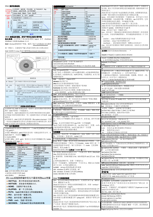
LINUX系统是多进程、多用户和交互式的计算环境。
退出系统文本界面下按<Ctrl-D>键或logout命令shutdown shutdown –h 8:00 shutdown –h +3Shell 是Linux系统的用户界面,提供了用户与内核进行交互操作的一种接口。
它接收用户输入的命令并把它送入内核去执行Shell也被称为Linux的命令解释器(command interpreter)Shell命令可以被分为内部命令和外部命令。
1.内部命令是shell本身包含的一些命令,这些内部命令的代码是整个shell代码的一个组成部分;2.内部命令,shell是通过执行自己代码中相应的部分来完成的3.外部命令的代码则存放在一些二进制的可执行文件或者shell 脚本中4.外部命令,shell会到文件系统结构(file system structure)中的一些目录去搜索那些文件名与外部命令的名字相同的文件,因为shell认为这些文件中就存放了将要执行的代码。
Shell 命令搜索路径1.Shell搜索的目录的名字都保存在一个shell变量PATH(在TC shell chsh命令来改变默认登录shell-l选项显示系统可用的shellecho $SHELL /bin/bash passwd修改密码/etc/passwd记录每一个用户的shell程序root:x:0:0:root:/root:/bin/bash[用户名]:[密码]:[UID]:[GID]:[身份描述]:[主目录]:[登录shell]manman -S2 open#选择第二个section1用户命令,2系统调用,3语言函数库调用,4设备和网络界面,5文件格式,6游戏和示范,troff的环境、7表格和宏,8关于系统维护的命令info<Q>退出<Space>滚屏whoam i:显示用户名gzip [opt][filename-list]-d 解压缩文件gzip 1.txt得到1.txt.gz文件gunzip执行解压缩zcat [opt][filename-list]解压文件输出到标准输出设备tar-c 建立备份文件-z压缩/解压一个存档文件-v详细地显示文件处理过程:用功能字母x解压文件的过程或存档文件的过程-f Arch 用Arch作为存档或恢复文件的档案文件-x从磁带中解压(恢复)文件;如果没有指定,默认对整条磁带址的特殊的表;模块所声明的任何全局符号都成为内核符号表的一部分;内核符号表出于内核代码段的_ksymtab,其开始地址和结束地址由C编译器所产生的两个符号来指定:_start_ksymtab和_stop_ksymtab从文件/proc/ksyms中以文本的方式读取内存地址符号名称【所属模块】模块引用计数:计数器存放在module对象的ecount域;当开始执行模块操作时,递增计数器;在操作结束时,递减这个计数器;维护三个宏__MOD_INC_USE_COUNT模块计数+1__MOD_DEC_USE_COUNT模块计数-1__MOD_IN_USE 计数非0时返回真;计数器的值为0时,可以卸载这个模块;计数器的当前值可以在/proc/modules(lsmod)中每一项的第三个域找到模块依赖:一个模块A引用另一个模块B所到处的符号存储管理保护模式下i386提供虚拟存储器的硬件机制i386的地址转换机制:地址总线32(36)位,物理内存4(64)GB;指令系统提供的逻辑地址为48位,虚地址空间64T虚拟内存(4G),内核空间(最高的1G字节由所有进程共享,存放内核代码和数据)和用户空间(较低的3G字节存放用户程序的代码和数据),每个进程最大拥有3G字节私有虚存空间;地址转换(通过页表把虚存空间的一个地址转换为物理空间中的实际地址) 进程用户空间的管理每个程序经编译、链接后形成的二进制映像文件有一个代码段和数据段进程运行是须有独占的堆栈空间进程用户空间linux把进程的用户空间划分为一个个区间,便于管理;一个进程的用户地址空间按主要由mm_struct和vm_area_structts结构来描述;mm_struct结构对进程整个用户空间进行描述;vm_area_structs结构对用户空间中各个区间(简称虚存区)进行描述mm_struct结构首地址在task_struct成员项mm中:struct mm_struct*mminclude/linux/sched.ccount(对mm_struct结构的引用进行计数。
汇编语言课后习题答案 王爽主编

补全编程,利用jcxz指令,实现在内存2000H段中查找第一个值为0的字节,找到后,将它的偏移地址存储在dx中。
assume cs:codecode segmentstart: mov ax,2000hmov ds,axmov bx,0s: mov ch,0mov cl,[bx]jcxz ok ;当cx=0时,CS:IP指向OKinc bxjmp short sok: mov dx,bxmov ax ,4c00hint 21hcode endsend start检测点9.3补全编程,利用loop指令,实现在内存2000H段中查找第一个值为0的字节,找到后,将它的偏移地址存储在dx中。
assume cs:codecode segmentstart: mov ax,2000hmov ds,axmov bx,0s:mov cl,[bx]mov ch,0inc cxinc bxloop sok:dec bxmov dx,bxmov ax,4c00hint 21hcode endsend start书P101,执行loop s时,首先要将(cx)减1。
“loop 标号”相当于dec cxif((cx)≠0) jmp short 标号检测点10.1补全程序,实现从内存1000:0000处开始执行指令。
assume cs:codestack segmentdb 16 dup (0)stack endscode segmentstart: mov ax,stackmov ss,axmov sp,16mov ax, 1000hmov ax, 0push axretfcode endsend start执行reft指令时,相当于进行:pop ippop cs根据栈先进后出原则,应先将段地址cs入栈,再将偏移地址ip入栈。
检测点10.3下面的程序执行后,ax中的数值为多少?内存地址机器码汇编指令执行后情况1000:0 b8 00 00 mov ax,0 ax=0,ip指向1000:31000:3 9a 09 00 00 10 call far ptr s pop cs,pop ip,ip指向1000:91000:8 40 inc ax1000:9 58 s:pop ax ax=8hadd ax,ax ax=10hpop bx bx=1000hadd ax,bx ax=1010h用debug进行跟踪确认,“call far ptr s”是先将该指令后的第一个字节段地址cs=1000h入栈,再将偏移地址ip=8h入栈,最后转到标号处执行指令。
微机原理及应用试卷(6套)含答案
学院:**学院专业班级:电子01 命题共4页第页1一填空题(每空1分,共25分)1.两个无符号数比较大小时,8086CPU用标志寄存器中的(1)标志判断结果。
2.内存单元1999H:0010H的段内偏移地址为(2),物理地址为(3);若(BP)=0010H,用指令MOV AL,[BP]取出该单元的内容,段寄存器(4)的值应为1999H。
3.8086CPU的寄存器CS:IP总是指示(5)地址,复位后CS:IP的值为(6),取出一个指令字节后,(7)自动加1。
在软件上可以通过(8)和(9)指令来改变IP的内容。
在硬件上可以用(10)或(11)来改变IP的内容。
4.在一个微机系统中有多个中断源,当出现两个中断源同时提出(12)时,CPU响应(13)的中断源,在此中断源的中断处理完毕后,再响应(14)的中断源。
5.8086/8088微处理器是否响应INTR引脚的信号由标志位(15)控制。
6.在80X86微处理器中,指令分配给寄存器SP的默认段寄存器是(16)。
7.INT 40H指令引发的中断,其中断向量存放在(17)H:(18)H开始的4个字节。
8.当ALE有效时,8086/8088的AD0-AD15引脚上传送的是(19)信息。
9.若一个数据块在内存中的起始地址为80A0H:1000H,则这个数据块的起始地址的物理地址为(20)。
10.分别用一条指令实现下列功能:1)栈顶内容弹出送BX(21)2)CX的内容加1,不影响进位标志位(22)3)AL的高四位置1(23)4)清进位标志(24)5)子程序结束返回(25)二选择题(10分)1Intel 8253/8254有()个16位计数器通道。
A、1B、2C、3D、42当8255A的端口A、端口B均工作在方式0的输入方式时,端口C可以作为()使用。
A、两个4位I/O端口或1个8位I/O端口B、状态端口C、部分引脚作端口A、端口B的联络信号D、全部作联络信号3欲使8086CPU工作在最大方式,其引脚MXMN应接()电平。
dsp复习重点电信

第二章1、DSP芯片内有3个CPU状态控制寄存器,用于表示工作状态和控制之用,分别说明是哪3个寄存器,并指出其中的状态位或者控制位。
ARP,DP,XF,INTM,IPTR,MP/MC,OVLY,DROM的作用。
’C54x提供三个16位寄存器来作为CPU状态和控制寄存器,它们分别为:状态寄存器0(ST0)状态寄存器1(ST1)工作方式状态寄存器(PMST) ST0和ST1主要包含各种工作条件和工作方式的状态;PMST包含存储器的设置状态和其他控制信息。
1.状态寄存器0(ST0)表示寻址方式和运行状态。
DP:数据存储器页指针。
用来与指令中提供的7位地址结合形成1个16位数据存储器的地址。
OVA/B:累加器A/B的溢出标志。
用来反映A/B是否产生溢出。
C:进位标志位。
用来保存ALU加减运算时所产生的进/借位。
TC:测试/控制标志。
用来保存ALU测试操作的结果。
ARP:辅助寄存器指针。
用来选择使用单操作数间接寻址时的辅助寄存器AR0~AR7。
2.状态寄存器1 (ST1)表示寻址要求、初始状态的设置、I/O及中断的控制等。
BRAF:块重复操作标志位。
用来指示当前是否在执行块重复操作。
BRAF=0 表示当前不进行重复块操作;BRAF=1 表示当前正在进行块重复操作。
CPL:直接寻址编辑方式标志位;用来指示直接寻址选用何种指针。
CPL=0 选用数据页指针DP的直接寻址;CPL=1 选用堆栈指针SP的直接寻址。
XF:外部XF引脚状态控制位。
用来控制XF通用外部输出引脚的状态。
执行SSBX XF=1 XF通用输出引脚为1;执行RSBX XF=0 XF通用输出引脚为0。
HM:保持方式位;响应HOLD信号时,指示CPU是否继续执行内部操作。
HM=0 CPU从内部程序存储器取指,继续执行内部操作。
HM=1 CPU停止内部操作。
INTM:中断总开关INTM=0 开放全部可屏蔽中断;INTM=1 禁止所有可屏蔽中断。
0:保留位,未被使用,总是读为0。
彻底搞定C指针(最新修订版)

彻底搞定C指针(完全版·修订增补版)著=姚云飞修订=丁正宇前言姚云飞先生的大作《彻底搞定C指针》是互联网上中文C/C++界内为数不多的专门阐述C指针问题的优秀文献资源之一。
正如书名所示,对于那些学习了C基础知识却始终对C指针不得要领的读者,或者那些已经长期被C指针困扰的读者,作者致力于彻底解决他们在这方面的难题。
为了达到这个目的,作者运用了许多生动与亲切的例子,深入浅出地讲透了C指针的原理与机制,并辅以编程实践中最常用的惯例和技巧作为示范。
《彻底搞定C指针》是互联网上下载次数最多的针对C指针问题的中文资源之一。
现在,经由修订者的重新修订、编辑与排版,本书的《完全版·修订增补版》全新登场。
新版本中的技术用语更加清楚严谨,行文的结构层次更加分明,例子中的程序代码均通过编译以测试其精准性。
修订者希望这份新的成果能够令各位读者在C编程方面获得更多的益处,同时也期待着读者们宝贵的反馈信息。
再次向姚云飞先生致敬!目录前言 (1)目录 (2)修订说明 (3)A类:规范化 (3)B类:更正 (3)C类:明晰化 (4)D类:编译器 (4)第壹篇变量的内存实质 (5)1.先来理解C语言中变量的实质 (5)2.赋值给变量 (6)3.变量在哪里?(即我想知道变量的地址) (7)第贰篇指针是什么? (8)1.指针是什么东西 (8)第叁篇指针与数组名 (11)1. 通过数组名访问数组元素 (11)2.通过指针访问数组元素 (11)3.数组名与指针变量的区别 (12)4.声明指针常量 (13)第肆篇const int *pi与int *const pi的区别 (14)1. 从const int i 说起 (14)2.const int *pi的语义 (15)3. 再看int *const pi (16)4.补充三种情况 (18)第伍篇函数参数的传递 (20)1.三道考题 (20)2. 函数参数传递方式之一:值传递 (23)3. 函数参数传递方式之二:地址传递 (26)4. 函数参数传递方式之三:引用传递 (27)第陆篇指向另一指针的指针 (30)1. 回顾指针概念 (30)2.指针的地址与指向另一指针地址的指针 (31)3. 一个应用实例 (32)第柒篇函数名与函数指针 (37)1. 通常的函数调用 (37)2.函数指针变量的声明 (38)3.通过函数指针变量调用函数 (38)4.调用函数的其它书写格式 (39)5.定义某一函数的指针类型 (42)6. 函数指针作为某个函数的参数 (44)修订说明A类:规范化A1. C程序的代码段,以及行文中的代码的字体,均统一调整为Courier New,例如:- 类型说明符“int”、变量名“a”、地址表达式“&a”、函数名“Exchg1”等等均作调整。
Windows程序设计课程复习题
Windows程序设计复习题一选择题1 下列程序设计方法中,()是一种基于对象的程序设计方法。
A: MFC程序设计B: 使用WindowsAPI编程C: 使用VisualBasic语言编程 D: 使用C#程序设计语言编程2 MFC程序框架中,最先执行的函数是()。
A: WinMain函数B: CWinApp类的构造函数C: CWinApp类的InitInstance函数D: Cwnd的OnCreate函数3 CWinApp类中用()成员函数实现了对消息环的封装。
A: InitInstance( ) B: Run()C: OnIdle() D: WndProc()4 消息的4个参数中,表示消息类型的参数是()。
A: HWND hwnd B: messageID C: wParam D: lParam5下列各消息中,与程序的菜单命令、工具栏按钮或对话框按钮相对应的消息是()。
A: WM_CHAR B: WM_COMMAND C: WM_CREATE D: WM_PAINT6 MFC消息映射机制中,下列消息映射表BEGIN_MESSAGE_MAP(CGraphicsView, CScrollView)ON_WM_PAINT()END_MESSAGE_MAP()把WM_PAINT消息映射到()。
A: CGraphicsView类OnPaint函数B: CGraphicsView类OnDraw函数。
C: CScrollView类的OnPaint函数D: CScrollView类的OnDraw成员函数。
7 下列MFC类中,不直接支持消息映射的MFC基类是(),A: CCmdTarget B: CWinAPP C: CWnd D: CMap8 下列集合类中,其内部是使用散列表技术实现的MFC类的是()。
A: CArray B: CList C: CMap D: CPtrList9 下列CWnd类成员函数中,用于任何消息的可覆盖函数是()。
C指针详解(经典,非常详细)

总结课:让你不再害怕指针指针所具有的四个要素:指针的类型,指针所指向的类型,指针指向的内存区,指针自身占据的内存。
0前言:复杂类型说明要了解指针,多多少少会出现一些比较复杂的类型,所以我先介绍一下如何完全理解一个复杂类型,要理解复杂类型其实很简单,一个类型里会出现很多运算符,他们也像普通的表达式一样,有优先级,其优先级和运算优先级一样,所以我总结了一下其原则:从变量名处起,根据运算符优先级结合,一步一步分析.下面让我们先从简单的类型开始慢慢分析吧:int p;//这是一个普通的整型变量int*p;//首先从P处开始,先与*结合,所以说明P是一//个指针,然后再与int结合,说明指针所指向//的内容的类型为int型.所以P是一个返回整//型数据的指针int p[3];//首先从P处开始,先与[]结合,说明P是一个数//组,然后与int结合,说明数组里的元素是整//型的,所以P是一个由整型数据组成的数组int*p[3];//首先从P处开始,先与[]结合,因为其优先级//比*高,所以P是一个数组,然后再与*结合,说明//数组里的元素是指针类型,然后再与int结合,//说明指针所指向的内容的类型是整型的,所以//P是一个由返回整型数据的指针所组成的数组int(*p)[3];//首先从P处开始,先与*结合,说明P是一个指针//然后再与[]结合(与"()"这步可以忽略,只是为//了改变优先级),说明指针所指向的内容是一个//数组,然后再与int 结合,说明数组里的元素是//整型的.所以P 是一个指向由整型数据组成的数//组的指针int**p;//首先从P开始,先与*结合,说是P是一个指针,然//后再与*结合,说明指针所指向的元素是指针,然//后再与int 结合,说明该指针所指向的元素是整//型数据.由于二级指针以及更高级的指针极少用//在复杂的类型中,所以后面更复杂的类型我们就//不考虑多级指针了,最多只考虑一级指针.int p(int);//从P处起,先与()结合,说明P是一个函数,然后进入//()里分析,说明该函数有一个整型变量的参数//然后再与外面的int结合,说明函数的返回值是//一个整型数据int(*p)(int);//从P处开始,先与指针结合,说明P是一个指针,然后与//()结合,说明指针指向的是一个函数,然后再与()里的//int结合,说明函数有一个int型的参数,再与最外层的//int结合,说明函数的返回类型是整型,所以P是一个指//向有一个整型参数且返回类型为整型的函数的指针int*(*p(int))[3];//可以先跳过,不看这个类型,过于复杂//从P开始,先与()结合,说明P是一个函数,然后进//入()里面,与int结合,说明函数有一个整型变量//参数,然后再与外面的*结合,说明函数返回的是//一个指针,,然后到最外面一层,先与[]结合,说明//返回的指针指向的是一个数组,然后再与*结合,说//明数组里的元素是指针,然后再与int结合,说明指//针指向的内容是整型数据.所以P是一个参数为一个//整数据且返回一个指向由整型指针变量组成的数组//的指针变量的函数.说到这里也就差不多了,我们的任务也就这么多,理解了这几个类型,其它的类型对我们来说也是小菜了,不过我们一般不会用太复杂的类型,那样会大大减小程序的可读性,请慎用,这上面的几种类型已经足够我们用了.1、细说指针指针是一个特殊的变量,它里面存储的数值被解释成为内存里的一个地址。
Tc简介
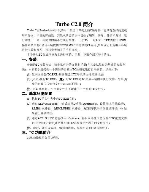
Turbo C2.0简介Turbo C由Borland公司开发的用于微型计算机上的C编译器。
它具有友好的集成用户界面、丰富的库函数。
其集成功能模块中包括了编辑、编译、链接和调试、运行功能于一体。
其提供的编译方式有两种:一是TC;一是TCC。
TCC类似于UNIX 操作系统中的C语言环境提供的CC和MS C中提供的CL命令(如果以它们为编译环境进行实验和开发,可以参考相关的手册资料)。
本手册以TC集成环境为主进行实验。
因此,下面介绍其基本情况。
一.安装传统的TC安装方法,请参见有关的文献和手册(尤其是以软盘为基础的安装方法)。
本实验手册提供一个简洁的自解压TC压缩包进行自动安装。
步骤如下:(1)复制压缩包(TC.EXE)到准备建立TC环境的文件夹或目录;(2)(双击)执行TC.EXE;(注:此TC.EXE是TC集成环境的可执行文件,与第(1)步的自解压压缩包文件TC.EXE不同!)注:可以观察到,在当前文件夹下新建了一个新的TC文件夹。
二.基本环境配置(1)执行TC子文件夹中的TC.EXE文件;(2)通过ALT+O(Options),然后选择D功能(Directories),设置基本寻找路径:1)LIB目录路径;2)INCLUDE目录路径;3)C程序代码所在目录路径;4) 结果输出目录路径;(3)通过ALT+O下的S功能(Save Options),将目录路径信息保存在TC配置文件TCCONFIG.TC中(通常都在TC.EXE执行文件所在的文件夹中) 注:此时,就可以编辑、编译和链接、执行相关的C语言程序了。
三.TC功能简介总体功能模块如图1所示。
图1 Turbo C主界面(编辑界面)运行TC进入的集成环境主界面(图1),可以看到有File, Edit, Run, Compile, Project, Options, Debug, Break/Watch等功能模块。
其中,各菜单项名的第一个字符是红色,表明该字符是选择该菜单项的热键。
PMON使用手册

STC单片机中双数据指针的使用方法[宝典]
![STC单片机中双数据指针的使用方法[宝典]](https://img.taocdn.com/s3/m/73b03b7ea55177232f60ddccda38376baf1fe0e3.png)
STC单片机中双数据指针的使用方法STC89系列单片机对数据指针也进行了扩展,由传统51的单数据指针,变成了双数据指针,并设置了相应的特殊功能寄存器对其进行控制,从而为应用系统设计中数据快速切换与访问提供了条件。
下面就对双数据指针的使用方法进行介绍。
在介绍中会涉及较多的汇编语言的内容,但非常简单,读者可以翻阅相关手册,或依程序中的注释理解。
双数据指针特殊功能寄存器GF2:通用功能用户自定义位DPS:DPTR寄存器选择位0:DPTR0被选中1:DPTR1被选中单片机中有两个16位的数据指针,DPTR0与DPTR1。
当DPS选择位为0时,选DPTR0,当DPS选择位为1时,选择DPTR1。
AUXR1特殊功能寄存器,位于A2H单元中,其中的位是不可以位寻址的。
但可以采用位操作的方式对DPS位进行置1或清零。
由于DPS位位于第0位,因此可以对AUXR1寄存器用INC(汇编中为INC,C中可以用++运算符),使DPS位反转,由0变为1或由1变为0,即实现双数据指针的快速切换。
用以下应用例程来说明其使用方法(只含核心代码):;此程序用以说明STC单片机中双数据指针的使用方法CLR A ;累加器A清零MOV AUXR1,A ;将A的值0传送给AUXR1,选中DPTR0MOV DPTR,#1FFH;向DPTR0中装入地址1FFHMOV A,#000H ;向累加器A中装入000HMOVX @DPTR,A ;将A的值传送到DPTR0所指向的外部存储单元中去MOV DPTR,#2FFH;向DPTR0中装入地址2FFHMOV A,#0FFH ;向累加器A中装入0FFHMOVX @DPTR,A ;将A的值传送到DPTR0所指向的外部存储单元中去ORL AUXR1,#01H ;将DPS位置1,选中DPTR1MOV DPTR,#1FFH ;向DPTR1中装入地址1FFHMOVX A,@DPTR ;将DPTR1指向的外部储存单元中的值传送给AMOV P2,A ;将A中的值输出在P2口上LCALL L?0008 ;调用延时程序ANL AUXR1,#0FEH;将DPS位清零,选中DPTR0,请注意前面的程序是使用DPTR1,此时DPTR0中的地址并;没变仍是2FFHMOVX A,@DPTR;将DPTR0所指向的外部存储单元(地址为2FFH)中的值传送给AMOV P2,A ;将A中的值输出在P2口上LCALL L?0008 ;调用延时程序ORL AUXR1,#01H ;将DPS位置1,选中DPTR1,此时DPTR1中的地址值为1FFHMOVX A,@DPTR;将DPTR1指向的外部存储单元中的值传送给A,即1FFH地址单元上的值,000HMOV P2,A ;将A中的值输出在P2口上LCALL L?0009 ;调用延时程序ANL AUXR1,#0FEH ;将DPS位清零,选中DPTR0,DPTR0中的地址值仍为2FFHMOVX A,@DPTR;将DPTR0指向的外部存储单元中的值传送给A,即2FFH地址单元上的值,0FFHMOV P2,A ;将A中的值输出在P2口上NON_STOP:。
高质量C编程指南(1)

横河资料 功能块

CS 1000/CS 3000ReferenceFunction Block Details 功能块详细说明CONTENTS 目录PART-C Function Block Common C部分功能块C1. Structure of a Function Block ..................................................C1-1 功能块的构成C2. I/O Connection ..........................................................................C2-1 输入输出连接C2.1 Data Connection ........................................................................................... C2-3 数据连接C2.2 Terminal Connection................................................................................... C2-13 未端连接C2.2.1 Connection between Function Blocks ........................................... C2-14 功能块之间的连接C2.2.2 Connection by a Switch Block (SW-33, SW-91) ............................ C2-16 开关模块的连接C2.3 Sequence Connection ................................................................................ C2-19 序列连接C2.4 Connection between Control Stations....................................................... C2-22 控制点的连接C2.5 I/O Connection Information ........................................................................ C2-25 输入输出连接信息C3. Input Processing ......................................................................C3-1 输入处理C3.1 Input Signal Conversion ............................................................................... C3-5 输入信号的变换(转换)C3.1.1 Input Signal Conversions Common to Regulatory Control Blocksand Calculation Blocks ................................................................... C3-7 一般的输入信号到普通控制块和计算快C3.1.2 Input Signal Conversion for Logic Operation Blocks ...................... C3-19 输入信号连接逻辑运算快C3.2 Digital Filter ................................................................................................. C3-20 数字滤波C3.3 Integration ................................................................................................... C3-23 整合C3.4 PV/FV/CPV Overshoot ................................................................................ C3-26 Pv/fv/cpv 溢出C3.5 Calibration ................................................................................................... C3-28校准C3.6 Input Proce ssing in the Unsteady State .................................................... C3-30 动态的输入处理(操作)C3.6.1 Input Processing of the Regulatory Control Block inUnsteady State ........................................ C3-32普通控制块的动态的输入处理C3.6.2 Input Processing of the Calculation Block in Unsteady State ......... C3-34 动态的计算块输入处理C3.7 Input Proce ssing for Sequence Connection ............................................. C3-38 顺序快的输入处理C4. Output Processing....................................................................C4-1 输出处理(操作)C4.1 Output Limiter ............................................................................................... C4-8 输出限制C4.2 Output Velocity Limiter ............................................................................... C4-11 输出变化限制C4.3 Output Clamp .............................................................................................. C4-12 输出固定C4.4 Pre set Manipulated Output......................................................................... C4-19 预设操作输出C4.5 Output Tracking .......................................................................................... C4-21 输出跟踪C4.6 Output Range Tracking ............................................................................... C4-25 输出范围跟踪C4.7 Manipulated Output Index .......................................................................... C4-28 操作输出指示C4.8 Output Signal Conversion .......................................................................... C4-29 输出信号转换C4.8.1 No-Conversion ............................................................................. C4-32C4.8.2 Pulse Width Output Conversion .................................................... C4-36 脉冲输出转换C4.8.3 Communication Output Conversion .............................................. C4-42 通讯输出的转换C4.8.4 Output Signal Conversion of Logic Operation Blocks .................... C4-43 输出信号转换到逻辑运算块C4.9 Auxiliary Output .......................................................................................... C4-44 辅助输出C4.10 Output Proce ssing in Unsteady State ....................................................... C4-48 动态的辅助输出C4.11 CPV Pushback ............................................................................................ C4-49 运算输出协议C4.12 Output Proce ssing in Sequence Connection ............................................ C4-52 顺序连接的输出处理C5. Alarm Processing – FCS .........................................................C5-1报警处理C5.1 Input Open Alarm Check .............................................................................. C5-6 输入开路报警检查C5.2 Input Error Alarm Check ............................................................................... C5-8 输入误差报警检查C5.3 Input High-High and Low-Low Limit Alarm Check .................................... C5-10 输入高高限或者低低限报警检查C5.4 Input High and Low Limit Alarm Check ..................................................... C5-13 输入高限或者低限报警检查C5.5 Input Velocity Alarm Check ........................................................................ C5-16 输入点报警检查C5.6 Deviation Alarm Check ............................................................................... C5-19 偏差报警检查C5.7 Output Open Alarm Check ......................................................................... C5-24 输出开路报警检查C5.8 Output Fail Alarm Check ............................................................................ C5-26 输出故障报警检查C5.9 Output High and Low Limit Alarm Check .................................................. C5-27 输出高限或者低限报警检查C5.10 Bad Connection Status Alarm Check ........................................................ C5-29 C5.11 Proce ss Alarm Message ............................................................................. C5-30 过程报警报告C5.12 System Alarm Message 系统报警报告................................................. C5-31C5.13 Deactivate Alarm Detection 取消的报警监测............................................C5-32C5.14 Alarm Inhibition (Alarm OFF) 禁止的报警.................................... C5-33C5.15 Classification of Alarm Actions Based on Alarm Priority ......................... C5-35 分类的报警优先权限C5.15.1 Alarm Display Flashing Actions 报警显示闪光动作.................. C5-36C5.15.2 Repeated Warning Alarm 重复报警................................................ C5-38 C5.16 Alarm Processing Levels 报警处理的色彩级别 ................................... C5-39 C6. Block Mode and Status 模块的模式和状态....................C6-1 C6.1 Block Mode 块模式.................................................................. C6-2 C6.1.1 Basic Block Mode 基本块模式............................................... C6-3C6.1.2 Compound Block Mode 复合块模式....................................... C6-5C6.1.3 Block Mode Transition模块变换...................................... C6-13C6.1.4 Block Mode Change Command模块更改命令. ............................ C6-20C6.1.5 Block Mode Transition Condition模块转型的条件 ........... C6-21C6.2 Block Status................................................................................ C6-27C6.3 Alarm Status ................................................................................................ C6-28C6.4 Data Status .................................................................................................. C6-32C7. Process Timing ........................................................................ C7-1C7.1 Process Timing for Regulatory Control Block ............................................ C7-3 C7.1.1 Scan Period .................................................................................... C7-4C7.1.2 Order of Process Execution ............................................................ C7-7C7.1.3 Timing of Process I/O ................................................................... C7-11C7.1.4 Control Period for Controller Block ................................................ C7-26C7.2 Process Timing of Calculation Block......................................................... C7-30C7.3 Process Timing for Sequence Control Block ............................................ C7-35 C7.3.1 Execution Timing for Sequence Control Blocks ............................. C7-36C7.3.2 Output Timing of Sequence Table Blocks (ST16, ST16E).............. C7-40C7.3.3 Output Timing of a LC64 Logic Chart Block ................................... C7-41C7.3.4 Combination of Execution Timing and Output Timing .................... C7-42C7.3.5 Control Period and Control Phase for Sequence Table Blocks(ST16, ST16E).............................................................................. C7-43C7.3.6 Control Period and Control Phase for Logic Chart Block (LC64) .... C7-45C1. Structure of a Function Block 功能块结构A function block consists of the following components:一个功能块包括以下部分• Input and output terminals that exchange data with devices outside of the external function block输入和输出终端,与外部设备交换数据的外部功能块• Four processing functions of input processing, calculation processing, output processing, and alarm processing四个处理功能的输入处理,计算处理,输出处理,并报警处理• Constants and variable data used to execute processing functions. Especially,an abbreviated name called “data item” is assigned to data that is referenced orset during the operation.常量和变量用来执行数据处理功能。
高质量程序设计指南C++ C语言(经典第1版)林锐

2001
Page 3 of 101
高质量 C++/C 编程指南,v 1.0
2001年7月24日高质量cc编程指南v10版本历史版本状态作者参与者起止日期备注v09林锐200171至林锐起草草稿文件2001718v10林锐2001718至朱洪海审查v09正式文件2001724林锐修正草稿中的错误2001page2of101高质量cc编程指南v10目录目录前言6第1章文件结构1111版权和版本的声明1112头文件的结构1213定义文件的结构1314头文件的作用1315目录结构14第2章程序的版式1521空行1522代码行1623代码行内的空格1724对齐1825长行拆分1926修饰符的位置1927注释2028类的版式21第3章命名规则2231共性规则2232简单的windows应用程序命名规则2333简单的unix应用程序命名规则25第4章表达式和基本语句2641运算符的优先级2642复合表达式2743if语句2744循环语句的效率2945for语句的循环控制变量3046switch语句3047goto语句31第5章常量3351为什么需要常量3352const与define的比较3353常量定义规则3354类中的常量34第6章函数设计362001page3of101高质量cc编程指南v1061参数的规则3662返回值的规则3763函数内部实现的规则3964其它建议4065使用断言4166引用与指针的比较42第7章内存管理4471内存分配方式4472常见的内存错误及其对策4473指针与数组的对比4574指针参数是如何01-7-1 至 2001-7-18 2001-7-18 至 2001-7-24
pointer 使用方法

pointer 使用方法**引言**在C 和C++ 编程中,指针(pointer)是一种非常重要且强大的概念。
掌握指针的使用方法对于成为一名优秀的程序员至关重要。
本文将详细介绍指针的使用方法,帮助你更好地理解和运用指针。
**pointer 基本概念**指针是一种变量,它的值是另一个变量的内存地址。
在C/C++ 中,指针主要用于访问和操作内存中的数据。
指针变量声明的一般形式为:`type*variable_name`,其中`type` 表示指针指向的变量的数据类型,`variable_name` 表示指针变量名。
**pointer 使用方法**1.声明指针变量:如前所述,声明指针变量的一般形式为`type*variable_name`。
2.取地址运算:使用`&` 运算符获取一个变量的地址。
例如,若`a` 是一个整型变量,可以表示为`int a;`,则`&a` 表示变量`a` 的地址。
3.解引用运算:使用`*` 运算符访问指针指向的变量值。
例如,若`p` 是一个整型指针,可以表示为`int *p;`,则`*p` 表示指针`p` 指向的变量值。
4.指针运算:指针之间可以进行加减运算,如`p + 1` 表示指针`p` 向后移动一个存储单位(指针指向的数据类型的大小)。
**指针与数组**数组在C/C++ 中是一种重要的数据结构。
数组名实际上是一个指针,它指向数组的第一个元素。
例如,若`arr` 是一个整型数组,可以表示为`int arr[5];`,则`arr` 是一个指向整型的指针,数组的第一个元素值为`arr[0]`。
**指针与函数**在C/C++ 中,函数可以接受指针参数。
这允许函数修改传递给它的变量的值。
此外,指针还可以用于返回函数值。
例如,以下函数接受一个整型指针,并将乘以2 后的值存储在该指针指向的地址:```cvoid multiplyByTwo(int *p) {*p = *p * 2;}```**指针与字符串**在C/C++ 中,字符串是一种特殊的数组,可以用指针表示。
汇编语言程序设计教程(第二版)习题参考答案
汇编语言程序设计教程(第二版)习题参考答案第1章计算机基础知识1.计算机的应用分哪几个方面,请举例说明书中未提到的领域的计算机应用。
科学计算、数据处理、计算机控制、计算机辅助设计、人工智能、企业管理、家用电器、网络应用。
书中未提及的如:远程教育、住宅小区控制、飞行系统控制与管理等。
2.简述计算机的发展过程,请查阅相关资料,列出微机的发展过程。
电子管、晶体管、集成电路、大规模集成电路以IBM为例,微机的发展:4004、8008、8080、8086/8088、80286、80386、80486、Pentium 系列3.计算机的字长是怎么定义的,试举例说明。
计算机能同时处理二进制信息的位宽定义为计算机的字长。
如8086能同时进行16位二进制数据的运算、存储和传输等操作,该机器的字长为16位。
4.汇编语言中的基本数据类型有哪些?数值型数据和非数值型数据。
非数值数据如字符、字符串、逻辑值等。
(1)7BCH=011110111100B=1980D(2)562Q=101110010B=370D(3)90D=01011010B=5AH(4)1110100.111B=164.7Q=74.EH30H~39H 41H~5AH 61H~7AH9.在汇编语言中,如何表示二进制、八进制、十进制和十六进制的数值?用相应进制的数值加上进制标记即可。
二进制用B,如10101010B八进制用Q,如437Q。
十进制用D或不用,如54D,或54。
十六进制用H,如27A8H10.完成下列二进制数的加减运算。
(1)10101010 + 11110000 (2)11001100 + 01010100=110011010 =100100000(3)11011010 - 01010010 (4)11101110 - 01001101=10001000 =1010000111.完成下列十六进制数的加减运算。
(1)0FEA9 - 8888=7621H (2)0FFFF - 1234=EDCBH(3)0EAC0 + 0028=EAE8H (4)3ABC + 1678=5134H12.完成下列BCD码的运算。
富士通单片机C语言手册(基础篇)

C 语言手册基ຫໍສະໝຸດ 篇3.1.2 无参数函数的定义方法 ............................................................................ 21 3.1.3 有参数函数的定义方法 ............................................................................ 21 3.1.4 空函数的定义方法 ................................................................................... 22 3.1.5 函数的返回值 .......................................................................................... 22 第二节 函数的调用 ............................................................................................. 22 3.2.1 函数的调用形式 ....................................................................................... 22 3.2.2 对被调用函数的说明................................................................................ 23 3.2.3 函数的参数和传递方式 ...........................................................
RPGLE 编程基础

RPGLE 编程基础本章主要介绍RPGLE语言的基础知识,包括规范表,操作码,编译方法等,通过本章的学习了解并初步掌握RPGLE的基本操作码并应用于简单编程,能编译程序并查看跟踪错误,能使用单步调试源码方法,并能读懂简单的RPGLE程序。
1 RPGLE规范表•H表(Control):指定程序使用的数据区•F表(File Description):文件说明•I表(Input):说明输入文件记录结构和数据•C表(Calculation):程序主体•O表(Output):说明输出文件记录结构常用的表有F表,D表,C表2 操作码简介RPGⅣ程序设计语言允许对数据进行多种类型的操作。
在计算规范表中写入的操作码指出要做的操作,通常是操作的缩写。
下表概括说明了每个操作码。
·一个空列表示此字段必须为空·所有下划线的字段都是必须的·一个下划线区域表明此位置没有结果指示器符号符号说明(H)四舍五入(整数的数值型结果)(N)不锁定记录(P)用空格或零填充结果(D)操作描述符或日期字段(T)时间字段(Z)时间标记字段+ 正的- 负的BL 空格BN 数值型空格BOF 文件头EOF 文件尾EQ 等于ER 错误FD 找到HI 大于IN 指示器LD 小于LR 最后一个记录 NR 没有找到记录 NU 数字OF offON onZ 零ZB 零或空格3 程序代码行的编写3.1 最简单的RPGLE程序为便于理解,这里写一个最简单的RPGLE程序CL0N01Factor1+++++++Opcode&ExtFactor2+++++++Result++++++++Len++D+HiLoEq*************** Beginning of data ************************************* 0001.00 C 'HELLO WORLD' DSPLY 0002.00 C RETURN****************** End of data ****************************************这个程序编译成功,并调用(CALL 程序名),就是在屏幕上反白显示“HELLO WORLD”字样。
- 1、下载文档前请自行甄别文档内容的完整性,平台不提供额外的编辑、内容补充、找答案等附加服务。
- 2、"仅部分预览"的文档,不可在线预览部分如存在完整性等问题,可反馈申请退款(可完整预览的文档不适用该条件!)。
- 3、如文档侵犯您的权益,请联系客服反馈,我们会尽快为您处理(人工客服工作时间:9:00-18:30)。
可以用相等测试运算符和关系运算符比较两个指针,但是除非他们指向同一个数组中的元素,否则这种比较一般没有意义。相等测试运算符则一般用来判断某个指针是否是NULL,这在本文后面提到内存操作中有一定的用途。
C语言中的数组和指针有着密切的关系,他们几乎可以互换,实际上数组名可以被认为是一个常量指针,假设a是有五个元素的整数数组,又已用赋值语句
一般的结构包含若干成员,而自引用结构必定包含一个指针成员,该指针指向与自身同一个类型的结构。例如,如下结构定义就定义了一个自引用结构:
struct node{
int data;
struct node *nextptr;
};
通过链节nextptr可以把一个struct node类型的结构与另一个同类型的结构链在一起。我们可以通过自引用结构建立有用的数据结构,如链表、队列、堆栈和树。考虑到篇幅问题与难度关系,笔者仅就比较基本的单向链表给出机械工业出版社《C程序设计教程》(第二版)中的源程序。我不推荐初学者过早接触数据结构,因为其中涉及了二级指针和自引用结构的大量应用,在打牢基础之前基本不可能完全读懂程序就更不要说运用了。对数据结构有兴趣的同学可以再和我进行交流。
例如程序已用声明语句
int *ptra, a=3;
声明了整型变量a(值为3)与指向整数值的指针a,那么通过赋值语句
ptra=&a;
就可以把变量a的地址赋给指针变量ptra。需要注意的是不可将运算符&用于常量、表达式或存储类别被声明为register的变量上。被赋值后的指针可以通过运算符*获得它所指向的对象的值,这叫做“指针的复引用”,例如打印语句
void malloc(size_t size); 分配由size指定大小的对象空间。函数返回一个空指针或指向所分配空间的指针。
void *realloc(void *ptr, size_t size); 将ptr所指对象的大小改为size指定的大小。在新旧空间的较小空间中的对象的内容不被改变。如果新空间大,该对象新分配部分的值是不确定的。若ptr是空指针,函数realloc的行为类似指定空间的函数malloc。如果size为零且ptr不是空指针,其释放所指向的对象。函数realloc返回一个空指针或指向可能移动了的分配空间的指针。
char s[]="this is a test.";
for (;*s='\0';s++)
printf("%c", *s);
是错误的,因为它试图在循环中改变s的值,而s实际上是一个常量指针。
在本部分的最后,说一说指向函数的指针。指向函数的指针包含了该函数在内存中的地址,函数名实际上就是完成函数任务的代码在内存中的起始地址。函数指针常用在菜单驱动系统中。
void swap(int *a, int *b)
{
int temp;
temp=*a;
*a=*b;
*b=temp;
}
就实现了两个整数的交换,在调用函数swap时,需要用两个地址(或两个指向整数的指针)作为参数,比如
swap(&num1, &num2);
其中num1和num2是两个整型变量,这样他们的值通过调用swap函数便得到了交换。需要指出的是,传递数组不需要使用运算符&, 因为数组名实际上是一个常量指针,然而传递数组元素就不同了,仍需要以元素的地址作为参数才能在函数中修改元素的值并返回调用函数。
由此可见,尽管指针通常以变量的地址作为其值,但有时候它指向的地址根本就没有变量名,这时候只能通过复引用指针进行一系列的操作。
D——能有效地表示复杂的数据结构(本部分内容建议初学者在弄清一切基本概念之前可以先不看)
在初学者接触令人费解的数据结构之前,必须先了解两个新的概念——“指向指针的指针”(也称二级指针)和“自引用结构”。
数组的各元素在内存中是连续存放的,这是指针运算的基础。现在假设在一台整数占4个字节的机器上,指针ptr被初始化指向整型数组a(共有三个元素)的元素a[0],而a[0]的地址是40000,那么各个变量的地址就会如下表所示:
表达式 ptra &a[0] &a[1] &a[2]
表达式的意义 指针ptra的值 元素a[0]的地址 元素a[1]的地址 元素a[2]的地址
一级指针包含一个地址,该地址中存放具体的值,而二级指针包含的地址中存放的是另一个地址,因此也可以说二级指针是指向指针的指针。
声明一个二级指针要使用**,例如:
int **ptr;
声明了一个指向整数的二级指针。二级指针到底有什么用呢?其实就像通过给函数传递地址,我们就可以修改具体的值一样,给一个函数传递二级指针,就可以将修改地址并将其返回调用函数,这在数据结构的管理上相当重要。
注:这些函数的原型在通用工具头文件<stdlib.h>中。
运用这些函数我们可以实现动态数据结构的处理,举个简单的例子,我们要模拟建立变长数组,只需使用如下语句:
int n, *ptr;
scanf("%d", &n);
ptr=malloc(n*sizeof(int));
这样,系统就分配了存放有n个元素的数组所需要的空间,ptr存储了分配内存的首地址,之后通过指针的复引用即可进行赋值等操作。需要提醒的是,如果没有可用的内存,在调用malloc函数时就返回NULL指针,所以这时一般应判断一下指针是否为NULL再进行下一组
如前文所述,数组名与字符串名都是常量指针,指针和数组名有时候是可以替代的。用指针编写数组下标标达式可节省编译时间,而且有时表示相对偏移量会更加方便,这方面的技巧本文就不多介绍了。
C——能动态地分配空间并直接处理内存地址
不像BASIC等一些其他高级语言,C语言要求同一层次中声明语句不能被置于任何执行语句之后,这决定了C中的数组是完全静态的,因为数组的长度必须在声明的时候确定,也就是说不能通过输入语句之类的方法临时决定数组的大小,要想建立和维护动态的数据结构就需要实现动态的内存分配并运用指针进行操作。
printf("%d", *ptra);
就会打印出指针变量ptra所指向的对象的值(也就是a的值)3。如果被复引用的指针没有被正确的初始化或没有指向具体的内存单元都会导致致命的执行错误或意外地修改重要的数据。printf的转换说明符%p以十六进制整数形式输出内存地址,例如在以上的赋值后,打印语句
五、学习指针与内存的一点建议
ptra+=2;
的结果是40000+4*2=40008, ptra也随之指向元素a[2],同理,诸如语句
ptra-=2;
ptra++;
++ptra;
ptra--;
ptra--;
等的运算原理也都与此相同,至于指针与指针相减,则会得到在两个地址之间所包含的数组元素的个数,例如ptra1包含存储单元40008,ptra2包含存储单元40000,那么语句
给函数传递参数的方式有两种,即传值和传引用,C语言中的所有函数调用都是传值调用,但可以用指针和间接引用运算符模拟传引用调用。在调用某个函数时,如果需要在被调用的函数中修改参数值,应该给函数传递参数的地址。当把变量的地址传递给函数时,可以在函数中用间接引用运算符*修改调用函数中内存单元中的该变量的值。比如我们无法在只用传值调用的情况下在函数中完成两个数的交换,因为它要求修改两个参数的值,但通过传地址模拟传引用调用即可轻松地实现这一点,例如函数:
表达式的值 40000 40000 40004 40008
必须注意,指针运算不同于常规的算术运算,一般地,40000+2的结果是40002,但当一个指针加上或减去一个整数时,指针并非简单地加上或减去该整数值,而是加上该整数与指针引用对象大小的乘积,而对象的大小则和机器与对象的数据类型有关。例如在上述情况下,语句
ptr1 = (int *) ptr2;
来实现。唯一例外的是指向void类型的指针(即void *),因为它可以表示任何类型的指针。任何类型的指针都可以赋给指向void类型的指针,指向void类型的指针也可以赋给任何类型的指针,这两种情况都不需要使用强制类型转换。
但是由于编译器不能根据类型确定void *类型的指针到底要引用多少个字节数,所以复引用void *指针是一种语法错误。
TC操作手册之---指针与内存操作
下面来介绍C语言功能最强大的特点,同时也是相对而言比较难掌握的概念之一——指针。
一、指针的基本概念
如同其它基本类型的变量一样,指针也是一种变量,但它是一种把内存地址作为其值的变量。因为指针通常包含的是一个拥有具体值的变量的地址,所以它可以间接地引用一个值。
二、指针变量的声明、初始化和运算符
声明语句
int *ptra, a;
声明了一个整型变量a与一个指向整数值的指针ptra,也就是说,在声明语句中使用*(称为“间接引用运算符”)即表示被声明的变量是一个指针。指针可被声明为指向任何数据类型。需要强调的是,在此语句中变量a只被声明为一个整型变量,这是因为间接引用运算符*并不针对一条声明语句中的所有变量,所以每一个指针都必须在其名字前面用前缀*声明。指针应该用声明语句或赋值语句初始化,可以把指针初始化为0、NULL或某个地址,具有值0或NULL的指针不指向任何值,而要想把某个变量地址赋给指针,需使用单目运算符&(称为“地址运算符”)。
ptra = a;
将第一个元素的地址赋给了指向整数的指针ptra,那么如下的一组表达式是等价的:
a[3] ptra[3] *(ptra+3) *(a+3)
它们都表示数组中第四个元素的值。
