电源方案12v1.5A详细设计
直流稳压电源实验报告

实验报告——直流稳压电源班级:13专电子2班学号:2013253827姓名:冯杰指导老师:戴仁村一、课程内容的概述各种电子电路和电子设备都需要稳定的直流电源,但电网提供的是50HZ的正弦交流电,这就需要将电网的交流电转换稳定的直流电,直流稳压电路就是实现这种转换的电子电路。
当今社会人们极大的享受着电子设备带来的便利,但是任何电子设备都有一个共同的电路--电源电路。
大到超级计算机、小到袖珍计算器,所有的电子设备都必须在电源电路的支持下才能正常工作。
当然这些电源电路的样式、复杂程度千差万别。
超级计算机的电源电路本身就是一套复杂的电源系统。
通过这套电源系统,超级计算机各部分都能够得到持续稳定、符合各种复杂规范的电源供应。
袖珍计算器则是简单多的电池电源电路。
不过你可不要小看了这个电池电源电路,比较新型的电路完全具备电池能量提醒、掉电保护等高级功能。
可以说电源电路是一切电子设备的基础,没有电源电路就不会有如此种类繁多的电子设备。
由于电子技术的特性,电子设备对电源电路的要求就是能够提供持续稳定、满足负载要求的电能,而且通常情况下都要求提供稳定的直流电能。
提供这种稳定的直流电能的电源就是直流稳压电源。
直流稳压电源在电源技术中占有十分重要的地位。
直流稳压电源的技术指标可以分为两大类:一类是特性指标,反映直流稳压电源的固有特性,如输入电压、输出电压、输出电流、输出电压调节范围;另一类是质量指标,反映直流稳压电源的优劣,包括稳定度、等效内阻(输出电阻)、纹波电压及温度系数等。
二、电路的设计框图及概述1、直流稳压电源设计思路①电网供电电压交流220V(有效值)50Hz,要获得低压直流输出,首先必须采用电源变压器将电网电压降低获得所需要交流电压。
②降压后的交流电压,通过整流电路变成单向直流电,但其幅度变化大(即脉动大)。
③脉动大的直流电压须经过滤波、稳压电路变成平滑,脉动小的直流电,即将交流成分滤掉,保留其直流成分。
直流稳压电源实验报告

实验报告——直流稳压电源班级:13专电子2班学号:2013253827姓名:冯杰指导老师:戴仁村一、课程内容的概述各种电子电路和电子设备都需要稳定的直流电源,但电网提供的是50HZ的正弦交流电,这就需要将电网的交流电转换稳定的直流电,直流稳压电路就是实现这种转换的电子电路。
当今社会人们极大的享受着电子设备带来的便利,但是任何电子设备都有一个共同的电路--电源电路。
大到超级计算机、小到袖珍计算器,所有的电子设备都必须在电源电路的支持下才能正常工作。
当然这些电源电路的样式、复杂程度千差万别。
超级计算机的电源电路本身就是一套复杂的电源系统。
通过这套电源系统,超级计算机各部分都能够得到持续稳定、符合各种复杂规范的电源供应。
袖珍计算器则是简单多的电池电源电路。
不过你可不要小看了这个电池电源电路,比较新型的电路完全具备电池能量提醒、掉电保护等高级功能。
可以说电源电路是一切电子设备的基础,没有电源电路就不会有如此种类繁多的电子设备。
由于电子技术的特性,电子设备对电源电路的要求就是能够提供持续稳定、满足负载要求的电能,而且通常情况下都要求提供稳定的直流电能。
提供这种稳定的直流电能的电源就是直流稳压电源。
直流稳压电源在电源技术中占有十分重要的地位。
直流稳压电源的技术指标可以分为两大类:一类是特性指标,反映直流稳压电源的固有特性,如输入电压、输出电压、输出电流、输出电压调节范围;另一类是质量指标,反映直流稳压电源的优劣,包括稳定度、等效内阻(输出电阻)、纹波电压及温度系数等。
二、电路的设计框图及概述1、直流稳压电源设计思路①电网供电电压交流220V(有效值)50Hz,要获得低压直流输出,首先必须采用电源变压器将电网电压降低获得所需要交流电压。
②降压后的交流电压,通过整流电路变成单向直流电,但其幅度变化大(即脉动大)。
③脉动大的直流电压须经过滤波、稳压电路变成平滑,脉动小的直流电,即将交流成分滤掉,保留其直流成分。
开关电源的设计及计算
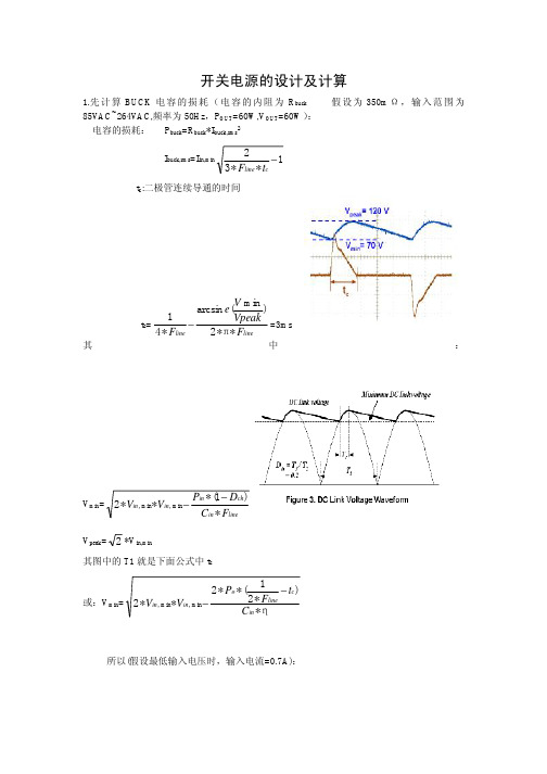
开关电源的设计及计算1.先计算BUCK 电容的损耗(电容的内阻为R buck 假设为350m Ω,输入范围为85VAC~264VAC,频率为50Hz ,P OUT =60W,V OUT =60W ):电容的损耗:P buck =R buck *I buck,rms 2I buck,rms =I in,min1**32−cline t F t c :二极管连续导通的时间t c =linelineF VpeakV e F **2)min(arcsin *41π−=3ms其中:V min =linein ch in in in F C D P V V *)1(***2min ,min ,−−V peak =2*V in,min其图中的T1就是下面公式中t c或:V min =η*)*21(**2**2min ,min ,in c line o in in C t F P V V −−所以(假设最低输入电压时,输入电流=0.7A):I buck,rms =I in,min1**32−cline t F =0.7*13*50*32−=1.3A P buck =350m*1.32=0.95W第一步计算电容损耗是为了使用其中的t c 值,电容的容量一般通用范围选2~3μ/W ,固定电压为1μ/W2.输入交流整流桥的计算(假设V TO =0.7V,R d =70m Ω)在同一个时间内有两个二极管同时导通,半个周期内两个二极管连续导通I d,rms =c line in t F I **3min ,=m3*50*37.0=1.04AP diodes =2*(V TO *2min ,in I +R d *I d,rms 2)=2*(0.7*27.0+70m*1.042)=640mW 一个周期内桥堆损耗为:P BR=2*P diodes =2*640m=1.28W桥堆功耗超过1.5W 时,我个人认为应加散热器(特别是电源的使用环境温度较高时)变压器和初级开关MOS :反激式开关电源有两种模式CCM 和DCM ,各有优缺点。
双12v电源实验报告

双12v电源实验报告1设计任务及要求设计一个输入220V 交流电压,经双路变压(两路16V )、整流、双路稳压后输出±12V 直流电压电源。
完成电路原理设计,元件选取及参数计算,并完成PCB 制板,进行软件仿真。
2直流稳压电源在电子电路及设备中,一般都需要稳定的直流电源供电,提供这种稳定的直流电能的电源就是直流稳压电源。
直流稳压电源在电源技术中占有十分重要的地位。
它由变压、整流、滤波、稳压四部分电路组成,如图1-1所示:图1-1直流电源的方框图(1)降压变压器,它将电网220V 交流电压变换成符合需要的交流电压,并送给整流电路,变压器的变比由变压器的副边电压确定。
(2)整流电路,整流电路将交流电压变换成脉动的直流电压。
再经滤波电路滤除较大的纹波成分,输出纹波较小的直流电压。
常用的整流滤波电路有全波整流滤波、桥式整流滤波等。
(3)滤波电路,可以将整流电路输出电压中的交流成分大部分加以滤除,从而得到比较平滑的直流电压。
(4)稳压电路,稳压电路的功能是使输出的直流电压稳定,不随交流电网电压和负载的变化而变化。
常用的集成稳压器有固定式三端稳压器与可调式三端稳压器。
工频交流脉动直流直流负载3电路设计整体原理图如图3-1所示:图3-1整体电路原理图3.1变压器按设计要求,变压器为220V输入双路16V输出,考虑到负载功率的问题,应该选择功率较大的变压器,本设计中选定EI型全铜变压器220V 转16V交流35W电感变压器。
35W已经完全满足设计要求和安全功率。
原理图和PCB封装分别如图3-2和图3-3所示:图3-2变压器原理图图3-3变压器PCB封装3.2整流电路本次设计采用单相桥式整流电路,它由四只二极管组成,其构成原u的整个周期内,负载上的电压和电流方则就是保证在变压器副边电压2向始终不变。
整流桥如图3-4所示图3-4单相桥式整流路在u2的正半周内,二极管D1、D3导通,D2、D4截止;u2的负半周内,D2、D4导通,D1、D3截止。
稳压电源设计

前言电子设备给人们日常生活带来极大便利,所有的电子设备只有在电源电路的支持下才能正常工作。
电子设备对电源电路的要求是能够提供持续稳定、满足负载要求的电能,而且通常情况下都要求提供稳定的直流电能。
提供这种稳定的直流电能的电源就是直流稳压电源。
论文描述了稳压电源的发展概况、主要组成部分以及常用器件和典型电路,揭示了稳压电源的工作原理。
详细介绍了设计方案的选择,变压、整流、滤波、稳压和保护电路等各个组成部分的选型和参数计算,并通过PROTEUS仿真电路中模拟的电压表和电流表显示出来。
给出了设计原理图。
对电路板进行了调试,文中给出了具体的调试过程、调试结果,以及调试过程中遇到的问题和解决方案,最终达到了设计要求。
目录摘要............................................. 错误!未定义书签。
第一章绪论 (5)1.1课题的研究背景及意义 (5)1.2稳压电源的发展 (5)1.3课题研究方法 (6)第二章设计内容及要求 (7)2.1 设计的目的及主要任务 (7)2.1.1 设计目的 (7)2.1.2 设计的主要任务及性能指标 (7)2.2 设计思想 (7)2.3 方案设定 (8)2.4 单元电路 (9)2.4.1电源变压器 (9)2.4.2整流电路 (10)2.4.3 滤波电路 (10)2.4.4 稳压电路 (11)2.5参数计算及器件选择 (12)2.5.1集成稳压器的选择 (12)2.5.2 电源变压器的选择 (12)2.5.3整流二极管及滤波电容的选择 (12)第三章稳压电源的分类、组成及技术指标 (14)3.1稳压电源的分类 (14)3.2直流稳压电源的基本组成 (14)3.3直流稳压电源的技术指标 (15)3.3.1特性指标 (15)3.3.2质量指标 (16)3.3.3极限指标 (16)第四章稳压电源常用元器件及电路 (17)4.1晶体二极管 (17)4.1.1晶体二极管的工作原理 (17)4.1.2硅整流二极管的主要参数及定义 (17)4.2整流电路 (17)4.2.1单相半波整流电路 (17)4.2.2单相全波整流电路 (18)4.2.3单相桥式整流电路 (19)4.3滤波电路 (20)4.3.1电容滤波电路 (20)4.3.2电感滤波电路 (21)4.3.3复合滤波电路 (21)4.4稳压电路 (22)4.4.1稳压管稳压电路 (22)4.4.2串联反馈型稳压电路 (22)4.4.3集成稳压电路 (23)4.5保护电路 (23)4.5.1过流保护 (23)4.5.2过热保护 (24)第五章电源的设计及制作 (26)第六章稳压电源的调试 (27)参考文献 (28)自我评价 (29)附录一 (30)附录二 (31)摘要本次试验从电源出发,利用学过的个中点血知识和有关经验,提出一项简单实用的多路直流电源设计方案,也是本次课程设计的目的。
基于ADP3181的交错并联同步BUCK电路的设计
基于ADP3181的交错并联同步BUCK电路的设计摘要:介绍了美国模拟器件公司的专用于电压调节模块(VRM)的开关电源控制芯片控制芯片ADP3181的主要特点,并设计了基于此芯片的三相交错并联同步整流BUCK电路,阐述了主电路和控制芯片外围电路的设计,给出了实验结果。
关键词:ADP3181 BUCK 交错并联设计微处理器及数字信号处理器(DSP)的不断发展给供电系统电压调节模块(VRM)带来了极大的挑战,主要表现在:(1)输出电压输出电压的降低。
目前VRM的输出电压大多数为1.3V~1.5V,为进一步提高速度,未来将要求输出电压降到1V以下。
(2)输出电流的增大。
芯片要求VRM的输出电流高达150A。
(3)微处理器的工作时钟频率已经高达2GHz~3GHz,未来几年将会达到4GHz,甚至10GHz。
因此,电流的瞬态变化非常大,将达到450A/?滋s。
(4)VRM 作为微处理器的供电单元,有限的主板空间要求其具有高效率、高功率密度和小体积。
因此,目前的VRM模块都采用多相多相交错并联的同步整流BUCK电路。
在相同的输出条件下,采用多相并联技术可有效减小每相滤波电感的体积,且开关管的电流仅仅是输出电流的几分之一,同时每相开关频率也可降低为原来的几分之一。
这样就可以减小输出电流纹波和降低开关损耗,从而提高变流器效率。
针对这种情况,许多电源管理芯片公司相继推出了用于低电压大电流VRM模块的多相输出高性能控制芯片,例如Intersil公司推出的ISL6566、ISL6566A,AD公司推出的ADP3181、ADP3191等。
这些器件实现了最快速的瞬态响应和最少数量的输出电容器,为业界提供了集成度最高且最经济的电源管理解决方案。
笔者在介绍了ADP3181芯片特点的基础上,设计了输入为12V、输出电压为1.5V、额定负载电流负载电流为65A的三相交错并联同步整流电路。
1 ADP3181内部结构及其特点 ADP3181是美国模拟器件公司推出的专用于多相同步BUCK电路的开关控制芯片,广泛应用于输入为12V的主板CPU供电电源上。
PQ3230反激变压器Microsoft Word 文档

3842电源,输入85~265V 输出 +/-18V 2A +12V 1.5A 48V 0.2A 用PQ3230做,NP 0.4*3 28T NS 0.4*4 6T 0.4*2 4T 0.25 16T,磁芯PC44,LP:380 ,实测温度为90度,线包外层,室温15度左右,请问设计上能改改,使温度下降点吗?回复1帖2帖itmsz团长917七2009-12-28 14:22回复2帖3帖cwhuang排长120六2009-12-28 17:46你的占空比选得过大,造成反激电压过高,故造成温升系数过大,你使用的UC3843,MOS管可能使IRF840去驱动,IRF840最高耐压为500V,我给你的设计如下,Np=20Tsx0.4mmx9股 Ns12v=3Tsx0.4mmx5股Ns18v=4Tsx0.4mmx6股 Ns48v=12Tsx0.31mmLP=0.1mH,选成多股数的主要目的是控制wire的集肤效应,也是减少散热的主要途径,但我有一事不明,在你的设计中,为值没有辅助绕组,是不是48V为辅助绕组,还有制样完成后,要进行调试,没有一次通过的电源或变压器,一个成功的设计要经过多少调试,才能让其稳定工作.由于时间的关系,上面的数据没有给你详细给你说明.还有你的原理图有点问题.回复3帖4帖zhouyh118旅长1594五2009-12-28 18:083842谢谢你的回复,反馈组忘了写了,是0.4*2 5T.,附电路,请帮忙分析。
回复4帖5帖cwhuang排长120四2009-12-29 17:08你的辅助绕组的相位标反了,应是3脚为起线,4脚为出线,才能到反激为你的IC供电.你的电路为什么不设计成TL431反馈,那样成本才不会太大,你用7815三端稳定器经济性和稳定不是太好,你打样了吗?回复5帖6帖cwhuang排长120三2009-12-29 17:16你的反馈绕组是不是12V,如果是请提高至15V,那样才能便稳定给IC供电,按我的方案试试看,你是否有板,如果有,先打样装机,测试看负载和空载是否合格,再调试,一个成功的工RD的经验是从调试中得到的.回复6帖7帖zhouyh118旅长1594二2009-12-29 19:06好的,谢谢你的帮助,我明天做个试一下。
小区商铺学校联网报警方案书

建 设 方 案 书建设单位:小区商铺校园防盗报警系统概述自动安全报警系统(简称CLSS)是现代科技发展的一种高科技产品。
它把人为管理、安全防范、信息处理有机地结合一起,使现代化管理手段有了极大的提高。
现代建筑群中所安装的CLSS系统应充分体现其现代化、科学化、综合化,同时其选用的设备应考虑先进性、可靠性、实用性,外形美观、布局合理,真正体现保安自动化、操作简单化。
近几年来,随着无线数据传输技术的成熟以及它拥有强大的功能、使用方法简单、免布线等明显的优点,无线安全自动报警系统在最近得到了飞速发展。
它使管理人员在控制室中就能观察到监控区域内的所有重要地点的情况,为保安系统提供良好的效果,同时也为降低区域内各种安全突发事件提供了良好的手段。
现代生活当中随着人们生活水平的提高,居民的安全意识也大大提高,现在新一代智能化小区所具备的保安系统除传统的技防之外更安装了安全自动报警系统,它完全解决了人力监控的弊端,并有效地防止生活上的一些突发事件的发生,如入室打劫、偷盗、煤气泄漏、火灾等事故都可以迅速消灭在萌芽状态。
它完全可以监控到房间的每一个角落而又不担心隐私外泄,是目前较为理想性价比较高的产品。
结合甲方的实际情况及甲方要求,我们本着配套齐全、功能完备、经济合理的原则做出了本系统的总体方案,下面我们将分别就设计思想,系统配置等做出详细的阐述。
一、设计原则自动安全报警系统是一种以预防、自动监控为主的内部封闭型监控管理网络,它可在规定范围内通过无线的方式传输各种意外、事故的数据信号,实行远距离监控,及时发现并处理问题。
自动安全报警系统的应用已经成为现代智能化小区及工厂、企业的保安、管理系统中一个必不可少的重要组成部分,它通过在楼层通道、房间、重要通道等处设置各类型探头,对现场的安全隐患进行自动监测控制,可以直观地掌握现场情况和记录事件事实,及时发现并避免可能发生的突发事件,为小区的安全运行与企业管理提供事实依据。
电源电路原理及维修

0.8
5
250K
3 RT
设置最大开启时间 连接电阻设置最大开启时间
1
5
70
4
RTZC 设置延迟时间
连接电阻设置过零点到开启的延迟时
0.9
5
20
间
5 IS
电流检测输入
电流检测输入
0
0
0
6
GND 接地
接地
0
0
0
7
OUT 驱动输出
输出驱动MOSTP
驱动脉冲
4.5
7
说电8 明压:值为VC数C字表FL电U源CK-45测量结果;IC供电
电源板参数介绍
电源板输入特性 输入电压:100~240V 50/60Hz 输入电流:120Vac满载时1.8A, 220Vac满载时1.0A 电源效率:满载时≥82% 待机功耗:≤0.5W PS-ON : 0~0.8V:关; ≥2V:开(实测东芝55U2600 1.3V)
电源输出特性
项目 输出电压 输出最小电流 输出额定电流 输出峰值电流 纹波噪声
待机时,PW-ON低电平,Q106截止,U103截止,Q104截止,无PFC VCC输出。
电源模块介绍
PFC模块(5591 芯片介绍)
引脚 标识
功能
说明
正常工作电压 (V)
对地正向阻值 (KΩ)
对地反向阻值 (KΩ)
1
FB
FB电压输入
监控PFC输出电压的输入
2.45
5
22
2
COMP 补偿
误差放大器输出端
电源模块介绍
背光驱动模块
工作原理: 84V供电给由L201、Q202、D201、C203、C204组成BOOST升压电路。 BOOST开关管受控于驱动IC MP3389A,12V经R207、JP1,C209滤波后进入IC第19脚(VIN)供电端, 经内部LDO稳压从20脚输出6V VCC,此脚外接C213滤波,ZD202稳压管起保护作用,VCC供IC内部电 路使用。BL-ON为背光开关信号,当BL-EN输入高电平,经R204、R218分压,C208滤除干扰后,进入 IC第EN脚,控制IC工作,同时BL-ON经R209、R217分压进入IC第ADIM脚,该脚电平>1.5V,没有模拟 调光。若BL-ON低电平时IC关闭。BL-ADJ为PWM调光信号,经R205、R219分压后输入IC第PWM脚, 作为PWM调光用,此时输入信号控制LED同步调光。 IC COMP脚外接R223、C212阻容网络,作为反馈环路相位调整。 IC OSC脚外接R227设定MOS管驱动脉冲的开关频率,公式: 。
详细技术参数一览表
详尽技术参数一览表序号 设备名称参数要求单位数目一、平台整体要求: 1、平台基本要求1)要求该工具平台能够知足学生经过软件模拟学习物联网感知层的硬件设备, 能够在软件环境下进行 RFID 、WSN 等各样设备的仿真切验。
2)要求上位机程序能够操作真切的硬件设备,也能够操作虚假 仿真中的仿真设备, 经过软件模拟出来的设备拥有和真切设备完 全一致的特征及接口。
供给 WiFi 、 Zigbee 有关的通信协议仿真能力。
3)要求该平台是纯软件系统,可直接部署在教课机房或学生自 己的电脑上,具备较强的灵巧性。
4)要求该平台能够虚假不一样应用处景,并与基础实验及开发实验相联合。
5)要求该平台拥有简单易用, 操作便利、 工程迅速搭建等功能。
2、平台功能要求:★ 1)要求供给完好的工程管理功能,包含新建、封闭、另存、导入等功能;★ 2)要求供给经过拖拽的方式进行工程内容编写功能; 3)要求每个模拟的设备模块化办理,实现对设备全部接口的完整仿真;物联网虚包含接口指令、1★ 4)要求将 RFID 设备的内部运转体制进行仿真,拟仿真切信令交互方式、卡的储存构造等;验平台套1★ 5)要求将 WSN 设备的网关及各样传感器的功能进行仿真,并 供给多种环境模拟器来保证明验的进行; 6)要求供给设备对齐、设备名称自定义等功能;★ 7)要求该平台可同时进行多个工程搭建及管理功能; ★ 8)要求该平台不限制硬件设备在每个工程中的使用次数; ★ 9)要求供给预制模板功能,关于复杂且常常用到的工程可提 前预制模板,无需让学生每次实验都从头搭建工程。
★ 3、设备种类要求: 该平台起码能够虚假出以下设备,以知足 教课使用。
1)电源: 3V2A 、 5V2A 、 9V1.5A 、 12V1A 等。
2) 15693 RFID 设备: 15693 读写器、 15693 标签、 15693 读写天线、 15693 多路复用器等。
3) RFID 14443 设备: 14443 读写器、 14443 标签。
TOP223Y开关电源设计
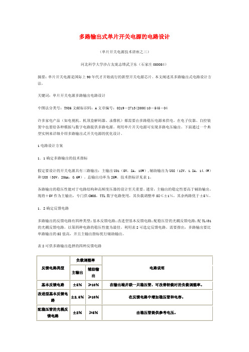
图 2 次级绕组的两种绕制方法 (a)分离式绕法(b)堆叠式绕法 另一种是堆叠式绕法。表 3 列出二者的优缺点,可供 表 3 次级绕组两种绕法的比较
绕制 方法
优点
缺点
分离 排列具有灵活性,可将输出电流较大的某 1 因漏感较大,在输出滤波电容上会产生峰值充电效 式绕 一路输出靠近初级,能把漏感引起的能量 应,导致轻载下的负载调整率变差。2 制造成本较高。 法 堆叠 式绕 法 损失减至最小。 1 能加强磁耦合。2 能改善轻载时的 稳压性能。3 骨架上的引脚较少(仅 4 个)。4 制造成本低。 3 骨架上的引脚较多(共 6 个)。 1 电压最低(或最高)的绕组须靠近初级。2 为降低 大电流时的漏感缺乏灵活性。
参考。图 2 分别示出它们的结构。分离式的每个绕组上仅传输与该路特定负载有关的电流。因 3 个次级绕 组互相独立,故在确定各绕组的排列顺序上有一定灵活性。现考虑到 5V(2A)和 12V(1.2A)输出绝大部 分的功率,因此可将这两个绕组中的一个靠近初级。最佳排列顺序是先绕 5V,再绕 12V,最后绕 30V,使 次级各绕组之间耦合最好,漏感最小。反之,若将 30V 绕组紧靠初级,由于 5V 及 12V 漏感较大,就会降低 电源效率,并且增加干扰。 堆叠式绕法是变压器生产厂家经常采用的方法。其特点是由 5V 绕组给 12V 绕组提供部分匝数及接地端;而 30V 绕组中则包含 5V、12V 绕组和新增加的匝数。各绕组的线径必须满足该路输出电流与其他路输出流过 它上面电流总和的要求。堆叠式绕法的技术先进,不仅能节省导线,减少绕组体积和降低成本,还可增加 绕组之间的互感量,加强耦合程度。举例说明,当 5V 输出满载,而 12V 和 30V 输出轻载时,由于 5V 兼作 12V、30V 的一部分,因此能减小这些绕组的漏感,可以避免因漏感使 12V 和 30V 输出电路中的滤波电容被 尖峰电压充电到峰值(亦称峰值充电效应),而引起输出电压不稳定。堆叠式绕法的不足之处是在确定哪 个次级绕组靠近初级时,灵活性较差。现将 5V 绕组作为次级绕组的始端。 在绕制时,特别推荐将多股导线并联后平行绕在骨架上。这样,能保证良好的覆盖性,增强初级与次级的 耦合程度。
TOP223Y开关电源设计实例
多路输出式单片开关电源的电路设计(单片开关电源技术讲座之三)河北科学大学沙占友庞志锋武卫东(石家庄050054)摘要:单片开关电源是国际上90年代才开始流行的新型开关电源芯片。
本文阐述其多路输出式电路设计方法。
关键词:单片开关电源多路输出电路设计中图法分类号:TN86文献标识码:A文章编号:0219-2713(2000)10-545-04许多家电产品(如电视机、机顶盒解码器、录像机)都需要由多路稳压电源来供电。
在电子仪器、自控装置中也要给各种模拟与数字电路提供多路电源。
利用单片开关电源可实现多路电压输出。
下面通过一个典型实例来详细介绍多路输出式开关电源的优化设计。
1电路设计方案1.1确定多路输出的技术指标假定要设计的开关电源具有三路输出:主输出UO1(5V,2A,10W),辅助输出为UO2(12V,1.2A,14.4W)和UO3(30V,20mA,0.6W)。
总输出功率为25W。
技术指标详见表1。
各路输出的稳压性能对于电路结构和高频变压器的设计至关重要。
通常,主输出的稳定性要高于辅助输出。
现将+5V作为主输出,专门供CMOS,TTL数字电路使用,其负载调整率SI≤±1%,其余两路优于±5%。
1.2确定反馈电路多路输出的反馈电路有四种类型:基本反馈电路;改进型基本反馈电路;配稳压管的光耦反馈电路;配TL431的光耦反馈电路。
以第四种电路的稳压性能为最佳。
利用表2可选定反馈电路。
需要指出,多路输出要比单路输出的SI值高,并且主输出指标优行辅助输出。
表2可供多路输出选择的四种反馈电路配TL431的光耦反馈电路±1%≤5%由TL431提供高稳定度的参考电压,主输出作为主要反馈信号,其余各路输出按一定比例反馈。
(1)基本反馈电路是利用反馈绕组间接获取输出电压的变化信号,因此不需要使用光耦合器。
该方案的电路最为简单,但开关电源的稳定性不高,难于把负载调整率SI降至±5%以下。
环形变压器初级匝数与线径计算

环形变压器初级匝数与线径计算环形变压器是一种常见的电力变压器,其结构呈环形,通常由两个或多个环形绕组组成。
通过改变不同绕组的匝数,可以实现不同的电压变换。
初级匝数和线径的计算对于环形变压器的设计和使用非常重要。
下面将详细介绍环形变压器初级匝数与线径的计算方法。
首先,我们需要明确一些基本概念。
初级匝数是指环形变压器的输入绕组的匝数,也就是连接电源的那一侧。
线径是指绕组中导线的直径或横截面积。
初级匝数和线径的选择与许多因素有关,包括所需的额定功率、输入电压和输出电压等。
为了计算环形变压器的初级匝数,我们可以使用下面的公式:N1 = (V1 × I1) / (4.44 × f × Bm × Ac × δ)其中,N1表示初级匝数,V1表示输入电压,I1表示输入电流,f 表示工作频率,Bm表示磁感应强度,Ac表示磁芯截面积,δ表示磁芯中心的饱和磁通密度。
假设我们需要设计一个输入电压为220V、输出电压为12V的环形变压器,工作频率为50Hz,磁感应强度为1.2T,磁芯截面积为20cm²,磁芯中心的饱和磁通密度为1.8T:N1 = (220 × I1) / (4.44 × 50 × 1.2 × 20 × 1.8)为了进一步计算初级匝数,我们需要知道输入电流I1的数值。
输入电流的数值可以通过所需的输出功率和输出电压来确定。
功率的计算公式为:P = V2 × I2其中,P表示输出功率,V2表示输出电压,I2表示输出电流。
如果我们需要设计一个输出功率为100W的环形变压器,输出电压为12V,则输出电流I2为:I2 = P / V2 = 100 / 12 = 8.33A现在我们可以将输入电流I1值代入初级匝数的计算公式中:N1 = (220 × 8.33) / (4.44 × 50 × 1.2 × 20 × 1.8)通过计算得到初级匝数N1的值,接下来我们可以计算线径。
LED驱动电源毕业设计
LED驱动电源的设计前言大功率LED特点及与其他光源比较LED被称为“绿色光源”当之无愧。
在照明行业中,将其与传统光源比较分析,某些方面表现出难以替代的优点:LED作为光源用于照明具有以下点:(1)耗电量低:光效为75lm/W的LED较同等亮度的白炽灯耗电减少约80%;(2)寿命长:产品寿命长达5万小时,24小时连续点亮可用7年;(3)亮度和色彩的动态控制容易:可实现亮度连续可调,色彩纯度高,可实现色彩动态变换和数字化控制;(4)外形尺寸灵活:可实现与建筑的有机融合,达到只见光不见灯的效果;(5)环保:无有害金属汞,无红外和紫外线辐射;(6)颜色:鲜艳饱和、纯正,无需滤光镜,可用红绿蓝三色元素调成各种不同的颜色,可实现多变、逐变、混光效果,显色效果极佳。
集这么多优点于一身,更让我们感受到大力推广使用LED是一项很有价值的工作。
因此,我们此次设计大功率LED驱动电路就是为了了解LED以及驱动的原理,从而学会制作大功率LED驱动电路。
而且通过制作进一步的了解各种在制作中用到的中小规模集成电路的作用及实用方法。
1 方案论证与选择大功率LED驱动方案现在还不成熟,考虑成本和性能有以下驱动方式,恒压驱动、恒流驱动、集成芯片驱动,各自有各自的优缺点。
1.1 恒压驱动采用阻容降压加上一个稳压二极管稳压的恒压驱动方式给LED供电(如图1.1-1),这样驱动LED的方式存在缺陷,主要是效率低,在降压电阻上消耗大量电能,甚至有可能超过LED所消耗的电能,且无法提供大电流驱动,因为电流越大,消耗在降压电阻上的电能就越大,所以很多产品的LED不敢采用并联方式,均采用串联方式降低电流。
其次是稳定电压的能力差无法保证通过LED电流不超过其正常工作值,设计产品时都会采用降低LED两端电压来供电驱动,这样是以降低LED亮度为代价的。
采用阻容降压方式驱动LED的亮度不能稳定,当供电电源电压低时LED的亮度变暗,供电电源电压高时LED 的亮度变亮些,LED正向电压的任何变化都会导致LED电流的变化。
电源电路图详解

电源电路图详解!用电路元件符号表示电路连接的图,叫电路图。
电路图是人们为研究、工程规划的需要,用物理电学标准化的符号绘制的一种表示各元器件组成及器件关系的原理布局图,可以得知组件间的工作原理,为分析性能、安装电子、电器产品提供规划方案。
电路图是电子工程师必学的基本技能之一,本文集合了稳压电源、DCDC转换电源、开关电源、充电电路、恒流源相关的经典电路资料,为工程师提供最新鲜的电路图参考资料,超全超详细,只能帮你到这了!一、稳压电源1、3~25V电压可调稳压电路图此稳压电源可调范围在3.5V~25V之间任意调节,输出电流大,并采用可调稳压管式电路,从而得到满意平稳的输出电压。
工作原理:经整流滤波后直流电压由R1提供给调整管的基极,使调整管导通,在V1导通时电压经过RP、R2使V2导通,接着V3也导通,这时V1、V2、V3的发射极和集电极电压不再变化(其作用完全与稳压管一样)。
调节RP,可得到平稳的输出电压,R1、RP、R2与R3比值决定本电路输出的电压值。
元器件选择:变压器T选用80W~100W,输入AC220V,输出双绕组AC28V。
FU1选用1A,FU2选用3A~5A。
VD1、VD2选用6A02。
RP选用1W左右普通电位器,阻值为250K~330K,C1选用3300µF/35V电解电容,C2、C3选用0.1µF 独石电容,C4选用470µF/35V电解电容。
R1选用180~220Ω/0.1W~1W,R2、R4、R5选用10KΩ、1/8W。
V1选用2N3055,V2选用3DG180或2SC3953,V3选用3CG12或3CG80。
2、10A3~15V稳压可调电源电路图无论检修电脑还是电子制作都离不开稳压电源,下面介绍一款直流电压从3V到15V连续可调的稳压电源,最大电流可达10A,该电路用了具有温度补偿特性的,高精度的标准电压源集成电路TL431,使稳压精度更高,如果没有特殊要求,基本能满足正常维修使用,电路见下图。
数控直流稳压电源毕业设计

数控直流稳压电源毕业设计智能控制设计大赛数控直流稳压电源目录摘要 (3)一、方案论证与比较 (4)1. 1系统供电部分 (4)1.2 控制器部分 (4)1. 3 显示部分 (4)1.4 键盘部分 (4)1. 5 数模/模数转换部分 (4)1. 6 掉电记忆部分 (5)二、系统的具体设计及实现 (5)2.1系统总框图 (5)2.2硬件设计 (6)2.2.1电源模块 (6)2.2.2DA转换模块 (6)2.2.3电压调整模块 (7)2.2.4键盘模块 (8)2.2.5EEPROM拓展模块 (8)2.2.6显示模块 (9)2.3软件设计 (10)2.3.1主程序流程 (10)2.3.2键盘程序流程 (11)2.3.3EEPROM读写流程 (12)2.3.4DAC0832程序流程 (13)2.3.5TLC1543程序流程 (13)三、测试、结果及分析 (14)3.1基本功能 (14)3.2发挥功能部分 (14)3.3其他发挥部分 (15)3.4详细的测试数据 (15)四、总结 (16)参考文献 (17)附录一、完整的系统原理图............................................................18附录二、完整的系统源代码 (19)数控直流稳压电源设计任务与要求一、设计任务设计并制作一个直流可调稳压电源。
二、设计要求1、基本要求:1)当输入交流电压为220v±10%时,输出电压在3-13v可调;2)额定电流为0.5A,且纹波不大于10mV;3)使用按键设定电压,同时具有常用电平快速切换功能(3v、5v、6v、9v、12v),设定后按键可锁定,防止误触;4)显示设定电压和测量电压,显示精度为0.01v。
2、扩展要求:1)输出电压在0-13v可调;2)额定电流为1A,且纹波不大于1mV;3)掉电后可记忆上次的设定值;4)两级过流保护功能,当电流超过额定值的20%达5秒时,电路作断开操作;当电流超过额定值的50%时,电路立即断开。
开关电源的PCB布线要求

开关电源的PCB布线设计开关电源PCB排版是开发电源产品中的一个重要过程。
许多情况下,一个在纸上设计得非常完美的电源可能在初次调试时无法正常工作,原因是该电源的PCB排版存在着许多问题.0、引言为了适应电子产品飞快的更新换代节奏,产品设计工程师更倾向于选择在市场上很容易采购到的AC/DC适配器,并把多组直流电源直接安装在系统的线路板上。
由于开关电源产生的电磁干扰会影响到其电子产品的正常工作,正确的电源PCB排版就变得非常重要。
开关电源PCB排版与数字电路PCB排版完全不一样。
在数字电路排版中,许多数字芯片可以通过PCB软件来自动排列,且芯片之间的连接线可以通过PCB软件来自动连接。
用自动排版方式排出的开关电源肯定无法正常工作。
所以,没计人员需要对开关电源PCB排版基本规则和开关电源工作原理有一定的了解。
1、开关电源PCB排版基本要点1.1 电容高频滤波特性图1是电容器基本结构和高频等效模型。
电容的基本公式是式(1)显示,减小电容器极板之间的距离(d)和增加极板的截面积(A)将增加电容器的电容量。
电容通常存在等效串联电阻(ESR)和等效串联电感(ESL)二个寄生参数。
图2是电容器在不同工作频率下的阻抗(Zc)。
一个电容器的谐振频率(fo)可以从它自身电容量(C)和等效串联电感量(LESL)得到,即当一个电容器工作频率在fo以下时,其阻抗随频率的上升而减小,即当电容器工作频率在fo以上时,其阻抗会随频率的上升而增加,即当电容器工作频率接近fo时,电容阻抗就等于它的等效串联电阻(RESR)。
电解电容器一般都有很大的电容量和很大的等效串联电感。
由于它的谐振频率很低,所以只能使用在低频滤波上。
钽电容器一般都有较大电容量和较小等效串联电感,因而它的谐振频率会高于电解电容器,并能使用在中高频滤波上。
瓷片电容器电容量和等效串联电感一般都很小,因而它的谐振频率远高于电解电容器和钽电容器,所以能使用在高频滤波和旁路电路上。
大功率开关电源设计

2016届毕业设计方案课题名称:《大功率开关电源的设计》所在学院牵引与动力学院班级动车134班姓名李升学号 ************指导老师2016届毕业设计任务书一、课题名称:多路输出单端反激式开关电源设计二、指导老师:邓小木三、设计内容与要求:1、课题概述:开关电源是通过控制开关晶体管开通和关断时间比率,维持稳定输出电压的一种电源。
开关电源被誉为高效节能电源,它代表着稳压电源的发展方向,现已成为稳压电源的主流产品。
开关电源内部关键元器件工作在高频开关状态,本身消耗的能量很低,电源效率可达80%一90%,比普通线性稳压电源效率提高近一倍。
本课题是设计多路输出单端反激式开关稳压电源。
主电路采用多路输出单端反激变换器结构,采用控制芯片UC3844实现电压电流双闭环控制,系统工作频率在50kHZ,输出+/-5V/0.5A(共4路),+/-12V/1A,,24V/1A 共7路隔离的电压。
2、设计内容与要求:1. 设计任务1)多路输出高频开关变压器设计;2)UC3844外围电路设计;3)开关电源保护电路设计;4)用PROTEL DXP绘制电路原理图,并制作PCB;5)开关电源焊接、调试;2.技术指标1)开关电源的输入电压:AC 185~250V2)开关电源输出电压及电流:+/-5V/0.5A(共4路),+/-12V/1A,,24V/1.5A3)开关电源的开关频率:50kHZ4)开关电源的效率:≥80%四、设计参考书1)张占松,蔡宣三.开关电源的原理与设计[M],北京:电子工业出版社,2004.2)周志敏,周纪海,纪爱华.开关电源实用电路[M],北京:中国电力出版社,2006. 3)黄继昌.电源专用集成电路及其应用[M],北京:人民邮电出版社,2006.4)王增福,李昶,魏永明.新编常用稳压电源电路[M],北京:电子工业出版社,2006. 5)黄俊,王兆安.电力电子变流技术[M],北京:机械工业出版社,2006.五、设计说明书要求1、封面2、目录3、内容摘要(200-400字左右,中英文)4、引言5、正文(设计方案比较与选择,设计方案原理、分析、论证,设计结果的说明及特点)6、结束语7、附录(参考文献、图纸、材料清单等)六、设计进程安排第1周:资料准备与借阅,了解课题思路。
冠能dm6-90说明书
冠能dm6-90说明书我给大家分享一下有关冠能DM6-90移动电源的一些相关信息。
首先来看一下产品信息:电源类型为LFA型1 KW (65 Ah)数码照相机供电型/输出型。
一、产品外观从产品外观上来看,冠能DM6-90移动电源确实让我眼前一亮,尤其是在外观设计方面,其给我的第一印象就是非常的简洁大方,机身尺寸为73.7*63.7*56.4 mm,重约120 g,在正常的重量下,机身厚度在5.2 mm左右,从外观上来说还是挺漂亮的。
同时还可以看到顶部采用了双插孔设计,其中可以插Micro USB接口和Type-C接口,插孔分别位于顶部两侧和底部的左右两侧。
除此之外,冠能DM6-90移动电源内部还配备了一个5 V/1.5 A智能电子稳压芯片和两个USB3.2 B接口,其中5 V/1.5 A智能电子稳压芯片可以实现高达10 A的电流输出速度;2个USB3.2 B接口用于充电时传输数据;而4个USB3.1 B接口则可以为数码相机提供一个强劲的电流输出能力。
在产品的顶部是产品的主要特色功能:智能显示电量和充电状态;三重防呆设计;五维安全保障;电源指示灯。
从产品的侧面来看,顶部与底部呈直角设计且还带有倒角设计。
二、产品参数及特点产品名称:冠能DM6-90移动电源。
功率:100 W (1 A)数码照相机供电(1 A)供电型/输出型,最高输出60 W (65 W),使用说明书上标明的额定电压为3.3 V-5V3C,最高输入电压为9 V,输出电压也达到9 V。
产品参数与包装内容相关:名称、参数、说明书、充电协议、接口配置及特价券等相关信息都在包装内进行了详细的介绍,但在电池容量方面,其内置容量为5000 mAh的锂离子电芯,并且还拥有5 A大电流充电接口以及双Type-C插口。
使用说明书上标明电池重量为206 g。
同时在产品说明书上也进行了相应的标注。
三、使用说明将移动电源的尾部电源插头插到电源线上,然后将电源线的一端插到电池的电源线上。
- 1、下载文档前请自行甄别文档内容的完整性,平台不提供额外的编辑、内容补充、找答案等附加服务。
- 2、"仅部分预览"的文档,不可在线预览部分如存在完整性等问题,可反馈申请退款(可完整预览的文档不适用该条件!)。
- 3、如文档侵犯您的权益,请联系客服反馈,我们会尽快为您处理(人工客服工作时间:9:00-18:30)。
Ref.
F1 VDR1 L1 L2 L3 R1,R2 R3,R4, R5 R6 R7 R8 R9 R10 R11 R12 R13 R14 R15 R16 R17,R18 C1 C2 C3 C4 C5 C6 C7 C8 C9 CX1 U1 D1,D2,D3,D4,D5 D6,D8 D7 D9 Q1 T1
Page: 9
9. Output Voltage Rising time
90VAC, No Load TRising=10.0mS
90VAC, Full Load TRising=26.4mS
Cost (US Cent) / unit
Sub-Total (Cent)
12V, 1.5A Adapter
iWatt Confidential – Do Not Copy
8 Feb 2007
Page: 6
6. Regulation, Ripple and Efficiency Measurement
iWatt Confidential – Do Not Copy
8 Feb 2007
Page: 2
2. Schematic
12V, 1.5A Adapter
iWatt Confidential – Do Not Copy
8 Feb 2007
Page: 3
3. Circuit Board Photograph
1(S) 4 (S) T1-B (F) T1-A (S)
2UEW 0.3mmx1 30T 2UEW 0.18mmx3 17T– Shield Triple Insulated Wire 0.55mmx1 13T – Secondary
Cut wire and leave it open at the end of winding
4. Transformer Construction
SCHEMATIC
Winding Direction Clockwise looking from Bottom side of Bobbin
Bottom Side
1
T1-B
13T Secondary
Primary
90T
T1-A 2 4
Bias/Sense 13T
EE25 Transformer
Top side
Primary Side
Secondary Side
Bottom side
iW1689 Digital Controller 12V, 1.5A Adapter iWatt Confidential – Do Not Copy 8 Feb 2007 Page: 4
90VAC, Full Load VOUT_MAX=11.96V
264VAC, No Load VOUT_MAX=12.52V
264VAC, Full Load VOUT_MAX=11.96V
12V, 1.5A Adapter
iWatt Confidential – Do Not Copy
8 Feb 2007
4 (F) 5 (S) T1-B(F)
2UEW0.18x4 13T –Bias Tape 1 Turn Triple Insulated Wire 0.55mmx1 13T – Secondary
1 4
5
ELECTRICAL SPECIFICATIONS:
1. 2. 3. Primary Inductance (Lp) = 650uH @10KHz Primary Leakage Inductance (Lk) < 40uH @10KHz Electrical Strength = 3KV 50/60Hz, 1 Min. (Test between pinsБайду номын сангаас1~5 to pins T1-A~T1-B)
7. Output VI Characteristics
VIN=90VAC,Temp.25℃ VIN=264VAC,Temp.25℃
V (2V/Div)
V (2V/Div)
I (0.5A/Div)
I (0.5A/Div)
Note: Output voltage is measured at DC cable end.
1. Specification
Description
Input Voltage Frequency No-load Input Power (264VAC) Output Output Voltage Output Current Output Ripple Voltage Total Output Power Continuous Output Power Over Current Protection Efficiency Environmental Conducted EMI Safety Ambient Temperature TAMB Meets CISPR22B / EN55022B Designed to meet IEC950, UL1950 Class II 0 40 °C
Description
FUSE,2A/250V 07K471 UU9.8, 25mH min. DM-Chock,Φ6X8,8uH CM-Chock,Φ10x5x6,600uH 2.4M,SMD-1206 820K,SMD-1206 68K, 2W 68R, 1W 10K,SMD-0603 TRIM,SMD-0603 2.7K,SMD-0603 8.2Kk,SMD-0805 10R,1/8W 1R,SMD-0805 22K, SMD-0805 10R, SMD-1206 1.5K,SMD-1206 100R,SMD-0805 1.0M,SMD-1206 33uF/400V,13x25.5,E-CAP 105℃ 1000uF/16V,10x20 ,E-CAP 105℃ 2.2nF,500V MIN 22pF,SMD-0805 1nF,SMD-0805 0.1uF,SMD-0805 22uF/50V,5x11.5,E-CAP 85℃ 330uF,6.3x11.5,E-CAP 85℃ 1nF/100V,SMD-0805 0.22uF,X-CAP,X2 iW1689,SOT23-5 FR107, DO-41 1N4148,SMD-DL35 FR104,DO-41 Y2010DN,TO-220 FQPF5N60C,TO-220 EE25 Total BOM (Based on 100K/M volume)
iW1689 Design with MOSFET For 12V1.5A Adapter
General Design Specification : 1. 2. 3. 4. AC Input Range 90-264Vac DC Output 12V, 1.5A Max Ripple 200mVp-p No Y-Cap design
T1-A(S) 2 (F)
2UEW 0.3mmx1 30T 2UEW 0.3mmx1 30T
MATERIALS:
1. 2. 3. 4. 5. Core : EE25 (Ferrite Material TDK PC40 or equivalent) Bobbin : EE25Horizontal with Extended Secondary stub. Magnet Wires (Pri) : Type 2-UEW – size see details Magnet Wire (Sec) : Triple Insulated Wires – size see details 1 Layer Insulation Tape : 1 4 Turn of 3M1298 or equivalent.
Free convection, sea level
Symbol
VIN fLINE
Min
90 47
Typ
Max
264
Units
VAC Hz W V A mVP_P
2 Wire
Comment
50/60
63 0.5
VOUT IOUT VRIPPLE
11.4 0
12
12.6 1.5 200
Measured at the End of DC Output cable
IOUT=1.5A @TA = 25 ℃ 20 MHz Bandwidth
POUT IOUT_MAX
18 2 78
W A %
Auto-restart
η
Measured at end of PCB, VIN = 90VAC POUT = 18W. (TA = 25 ℃)
12V, 1.5A Adapter
Page: 5
5. Bill of Material
Item
1 2 3 4 5 6 7 8 9 10 11 12 13 14 15 16 17 18 19 20 21 22 23 24 25 26 27 28 29 30 31 32 33 34 35 36 37
Qty.
1 1 1 1 1 2 2 1 1 1 1 1 1 1 1 1 1 1 1 2 1 1 1 1 1 1 1 1 1 1 1 5 2 1 1 1 1
VIN (VAC) IIN(mA) 8.9 117 90 208 298 392 9 98 115 174 247 318 16 60 230 103 146 187 18 56 264 94 132 168 PIN(W) 0.226 5.71 11.13 16.80 22.62 0.259 5.68 11.13 16.62 22.20 0.457 6.08 11.45 16.73 21.94 0.478 6.35 11.65 16.82 22.08 VOUT(V) 12.41 12.22 12.19 12.17 12.13 12.43 12.22 12.19 12.16 12.14 12.40 12.22 12.20 12.17 12.16 12.40 12.22 12.20 12.18 12.15 IOUT(A) 0 0.375 0.750 1.125 1.500 0 0.375 0.750 1.125 1.500 0 0.375 0.750 1.125 1.500 0 0.375 0.750 1.125 1.500 VRIPPLE (mVP-P) 20 102 100 165 190 20 90 110 140 145 20 90 105 120 120 22 90 120 130 120 4.583 9.150 13.703 18.225 72.17 78.54 81.47 82.54 Note: Output voltage measures end of PCB end 12V, 1.5A Adapter iWatt Confidential – Do Not Copy 8 Feb 2007 Page: 7 1.83 204 78.68 4.583 9.150 13.691 18.240 75.37 79.91 81.84 83.14 1.83 182 80.06 4.583 9.143 13.680 18.210 80.68 82.14 82.31 82.03 75.01 1.88 107 81.79 4.583 9.143 13.691 18.195 80.25 82.14 81.50 80.44 1.85 87 81.08 Meet CEC With lot of margins ! POUT (W) η(%) OCP (A) PIN_S/C (mW) Average η (%) CEC Standard η (%)
