派克液压系统UP3000-100国电使用说明书
Parker Hannifin PV系列电控油泵安装和设置手册说明书

Bulletin Hy11 PVI017/GBInstallation and setupmanualElectro-hydrauliccontrol for PV seriesDesign series³40, PV plusVariable displacementaxial piston pumpParker Hannifin GmbHHydraulic Controls DivisionGutenbergstr. 3841564 Kaarst, GermanyTel.:(+49) 2131-513-0Fax:(+49) 2131-513-230Figure 2: electronic module PQ0*-F00Figure 3: circuit diagram for electronic module PQ0*-F00compensator option, code PQ0*-P00 is shown in figure 5.Figure 5: electronic module PQ0*-P00 Beside the functions of version PQ0*-F00 for the proportional displacement control described in chapter 1 it also offers the control of a proportional pressure pilot valve type DSAE1007P07KLAF.Figure 6 shows the electronic circuit of this control electronic. The upper part is exactly what has been described in chapter 1 for module PQ0*-F00.The maximum current requirement for version PQ0*-P00 reaches up to 2.8 A, because now two proportional solenoids need to be supplied.The lower part in figure 6 shows the control of the proportional pressure pilot valve. Also for pressure setting either a voltage command (0 - 10 V) or a current command (0 - 20 mA) can be used. Also this command signal can be controlled by a potentiometer connected to the reference voltage pin 34.The pressure control circuit is equipped with an electronic network that linearizes the characteristic of the proportional pressure pilot valve (pressure over input signal). This network is dimensioned for Parker pressure valves.Figure 8: electronic module PQ0*-Q00The electronic circuit of this module is shown in figure 9. The difference to the circuit shown in figure 6 is the additional interfacefor a pressure sensor and the PID controllerfor a closed loop pressure control.As shown in figure 7, the pressure sensoris positioned in the pilot circuit. According to the differential pressure adjusted at the compensator valve, the system pressure is higher than the controlled pressure.Figure 9: electronic circuit of module PQ0*-Q00displacement.Figure 11: electronic module PQ0*-L00hydraulic circuit of a pump with ...WPR control (with shuttle valve subplate)Figure 16:shuttle valve subplate for p-Q-controlled pumps, code ...WPRsolenoid current,displacement control stagedisplacement control valve,code PVCF*PV**shuttle valve subplatepressure compensator stage, code PVCF*P2**f l o w Qpressure p 1pressuredisplacementshuttle valve insertinternal pressure port, G 1/4“ (second port opposite side)Figure 21: inductive positon transducer (LVDT), outside viewMAX-adjustment:Next the command for the displacement is to be increased, until the maximum displacement of the pump is reached. That can either be monitored by using the diagnosis output or a flow meter at the pump outlet. The maximum displacement is reached, if the displacement / flow does not further increase, even when the input command is still raised.In a control situation the solenoid should draw approx. 60 % of its nominal current (no-minal current 1,3 A; current in control situation 750 mA). Under these conditions the soleno-id provides approx. 50 % of its nominal force.That leads to a similar response for on- and offstroking. By turning the adjustment screw,this can be achieved. Clockwise turning increases the solenoid current (force).lock nutelectrical connectionset screw (basic adjustment of control valve)Figure 23: displacement control valve Figure 24: proportional displacement control valve with open set screwParker Hannifin GmbHHydraulic Controls Division Gutenbergstr. 38D 41564 KaarstTel.:+49 2131-513-0Fax:+49 2131-513-230Copyright 2001 by Parker Hannifin GmbH。
UPS界面说明和使用说明.docx
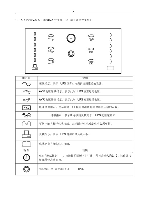
1.APC2200VA/ APC3000VA 台式机、 2U 机(联锁设备用):TEST指示灯说明在线指示,表示UPS正将市电提供给所连接的设备。
AVR电压降低指示,表示此时UPS校正过高电压。
AVR电压升高指示,表示此时UPS校正过低电压。
电池供电指示,表示此时UPS将电池能量提供给所连接的设备。
过载指示,表示所连接的负载高于UPS的额定功率。
更换电池 / 断开电池指示,表示断开电池或是电池必须更换。
负载指示,表示UPS电源所带负载大小。
电池充电 / 市电电压指示。
特性功能开机 / 测试按钮: 1、持续按前面板“ I ”键 1 秒可启动 UPS;2、按住此按TEST钮几秒钟启动自检。
关机按钮:按下此按钮可关闭UPS。
2.APC1000/ APC1500/ APC2000(联锁 /TDCS/ 列控设备用 ):TEST指示灯说明负载指示,表示 UPS电源所带负载大小。
电池充电 / 市电电压指示。
在线指示,表示 UPS正将市电提供给所连接的设备。
过载指示,表示所连接的负载高于UPS的额定功率。
电池供电指示,表示此时UPS将电池能量提供给所连接的设备。
故障指示灯:此灯亮表示UPS发生异常状况。
旁路指示灯:此灯亮表示负载电力直接由市电提供。
更换电池 / 断开电池指示,表示断开电池或是电池必须更换。
特性功能开机 / 测试按钮: 1、持续按前面板“ I ”键 1 秒可启动 UPS;2、按住此TEST按钮几秒钟启动自检。
关机按钮:按下此按钮可关闭UPS。
3.SANTEK_C1KR/C2KR (TDCS/CTC 设备用):1UPS ON2BATTERY3BYPASS4AC INPUT5ALARM指示灯说明负载指示灯: 1#~5#灯,表示在市电模式下负载容量。
电池容量指示灯: 1#~5#灯,表示在电池放电模式下电池容量。
UPS ON逆变指示灯 : 此灯亮表示负载电力由市电或电池经UPS提供。
BATTERY电池指示灯:此灯亮表示负载电力由电池经UPS提供。
液压精品培训资料派克:典型液压回路基本液压回路

制阀的切换,可以实现执行机构的往复运动或旋转运动。
02 03
换向阀
换向阀是方向控制回路中的核心元件,通过改变阀芯的位置来控制油液 的流动方向。根据结构和工作原理,换向阀可分为电磁换向阀、电液换 向阀和手动换向阀等。
典型应用
方向控制回路广泛应用于各种机械设备的液压系统中,如挖掘机、起重 机和机床等,实现执行机构的往复运动或旋转运动。
压力阀
控制油液压力,如溢流阀、减压阀、顺序阀等。
派克阀
• 流量阀:控制油液流量,如节流阀、调速阀等。
派克阀
应用场合 方向阀广泛应用于各种机械设备的液压系统。
压力阀和流量阀根据具体需求选择使用。
派克辅件
油箱
储存油液,散热冷却,去除气泡。
滤油器
过滤油液中的杂质和颗粒物,保持油液清洁。
派克辅件
• 密封件:防止油液泄漏和外部杂质进入系统。
压力控制回路
压力控制回路概述
压力控制回路是用于控制液压系统中油液压力的 回路。通过压力控制阀的调节,可以实现系统压 力的稳定或调节。
减压阀
减压阀是用于降低系统压力的元件,通过调节减 压阀的出口压力,可以实现执行机构所需的工作 压力。
溢流阀
溢流阀是压力控制回路中的重要元件,其作用是 限制系统最高压力,防止液压系统过载。当系统 压力超过溢流阀的设定压力时,溢流阀打开,油 液溢回油箱。
常工作和性能。
液压系统的分类
01
02
03
按传动方式分类
分为容积式液压传动和静 液式液压传动。
按工作介质分类
分为水液压传动和油液压 传动。
按能源形式分类
分为机械能液压传动、电 能液压传动和气压液压传 动等。
02
派克系列伺服阀安全操作及保养规程

派克系列伺服阀安全操作及保养规程伺服阀是一种在工程机械中广泛使用的重要液压元件。
为了确保机器的安全性能并延长使用寿命,对伺服阀的安全操作和保养至关重要。
安全操作1. 管理人员应对设备安全性能有深刻认识管理人员应该了解伺服阀的运作原理和相关的安全知识,以指导操作人员进行正确的操作和维修,确保设备的安全性能。
2. 操作人员应该经过专业培训操作人员应该经过相关机械设备的操作和维护培训,熟悉伺服阀的结构和工作原理,如何正确操作伺服阀,以及如何发现和解决设备故障。
3. 操作前应检查伺服阀的正常工作状态在操作伺服阀之前,必须检查各个连接部位的准确性,防止管道系统中的脏物、油泥等杂物进入伺服阀。
同时,要确保液压系统的压力和流量稳定,以确保伺服阀的正常工作状态。
4. 操作时应注意安全在操作伺服阀时,应注意操作规范,随时关注液压系统的压力和温度,防止操作员受伤或设备受损。
5. 关机后应注意设备安全在操作结束后,应关闭伺服阀开关,保留操作记录和安全事故记录,以及在伺服阀设备上贴上停机通知,防止其他人员误操作,造成设备和人员伤害。
保养规程伺服阀在使用了一段时间之后,需要进行定期保养来延长寿命和确保正常操作。
保养的主要内容如下:1. 定期更换油液油液是伺服阀正常工作的重要条件。
使用过长时间的油液含有很多杂质和水分,会严重影响伺服阀的工作性能。
因此,应定期更换油液并清洗油液管道系统。
2. 检查伺服阀管路和连接件伺服阀管路和连接件的损坏、老化和松动都会直接影响伺服阀的正常工作,因此应经常检查伺服阀管路和连接件是否正常。
3. 检查电磁阀组件和联轴器的工作状态电磁阀组件和联轴器等配件是伺服阀正常工作的核心部件之一,应该定期检查它们的工作状态,检查是否有磨损和松动现象,及时发现和解决问题。
4. 定期更换密封件伺服阀的密封件是伺服阀正常工作的保障。
长期使用后,密封件会因过度磨损而老化,导致液压系统泄漏。
因此,应定期对伺服阀进行密封件更换和维护。
液压系统使用说明书
液压操作中工作液的管理为获得液压设备较高的效率,预防事故的发生和保证稳定的性能,要进行一系列的维护和管理工作,而其中液压操作中工作液的维护和管理尤其特别重要,因此必须和液压工作液制造者一起预先充分考虑保养维护和管理的主要内容。
工作液的保养和维护的简单说明以及长期使用油的液压设备所必需检查的内容如下:1.工作液的种类使用L-HM46液压介质。
2.粘滞度范围所使用的工作液粘滞度范围从41.4-50.6厘司该粘滞度范围一般相当于工作液温度40°C,希望从工作液的制造者那里获得和所使用的液体操作液有关的粘滞度温度曲线。
3.清洁度系统要求NAS1638-※级4.定期检查试运行的初级阶段:运行500小时之后。
正常运转:2000小时。
取约1升工作液作为式样,请工作液的制造者进行对它检验。
5.更换正常的更换周期通常是4500小时,尽管检查结果是正常的,一般说来,应将全部液压工作液旧的尽可能的全部更换。
6.每天检查事项(1)变色—这种变色是由于水或空气的侵入而产生的。
(2)气味—特殊气味是由与油的玷污及变质之后而产生的。
(3)外界物质的侵入—由于外界物质的侵入有时造成工作液的提前变质。
(4)除水—从油储藏室最底部的排水管排水,每月进行一次。
试车运行的准备管道:充分的冲洗:杂质的等级10级以内NAS1638;管夹应准备充分:通常在直管路上,间隔1000MM-2000MM,当管道振动较大或弯曲点过多的情况下,管夹间距尽可能小一些;应有足够的耐压力:是工作压力的1.25-1.5倍。
电气:确定电机的运转方向:一般参照液压泵顶部铭牌上箭头方向和液压设备的装配图检查电机的运转方向。
特殊要求应先断开电机和油泵之间的连轴器,然后然电机单独运行以确定电机的旋转方向。
电磁控制阀的导电性实验:检查电路和电磁控制阀的一致性。
给每个电磁控制阀单独通电以确定磁体是否按照说明进行动作。
试车的程序1.加油加油时使用滤油小车,同时应注意不要让外界杂质或水进入到油箱中。
apc smart-ups 3000ux使用说明书
apc smart-ups 3000ux使用说明书输出输出功率容量 2700 瓦数/3000 VA最大可配置功率 2700 瓦数/3000 VA额定输出电压 230V输出电压失真满负荷时低于 5%输出频率(与主频率同步) 47 - 53 Hz(50 Hz 标称值),57 - 63 Hz( 60 Hz 标称值)波峰因数 up to 5 : 1 波形类型正弦波输出连接 (8) IEC 320 C13(2) IEC Jumpers(1) IEC 320 C19 输出电压可调范围可设置为220、230或240 输出电压输入额定输入电压 230V输入频率 50/60 Hz +/- 3 Hz (自动适应)输入端子类型 Schuko CEE 7 / EU1-16PBritish BS1363AIEC-320 C20 inlet 工作电压范围 160 - 286V输入电压范围 151 - 302V输出线长度 1.83米SUA系列的性能与优势可用性自动升压/降压无需使用电池,通过校正高低电压提供较好的可用性。
电源调节保护所连接的负载免受浪涌、尖峰电压、闪电和其他电源扰动的影响。
of work enthusiasm and forward-looking. The difficulties and problems of individual cadres indifferent masses as the buck passing, long, make some simple complex problems. Some cadres general talk about pay, do not take the initiative to undertake for the bitter and tired of the work, the lack of courage to play a positive attitude." corrective measures: (LED Leadership: Luo Mingjun, rectification time: before September 25th, insist for a long time) 1, effectively solve the enterprise less, help is not enough. In order to "turn style, solve problems, and do practical things, heart to heart" as the core, in accordance with the provisions of division of Labor Bureau, by the Bureau of Party members and cadres room composition the working group , to help enterprises solve problems, promote the construction of major projects; close ties with the masses, to ask for the people, ask for people to know the people, public opinion, the people, improve people's livelihood.智能电池管理通过智能、精确的充电技术获得最佳的电池性能、寿命和可靠性。
系列派克柱塞泵安全操作及保养规程
系列派克柱塞泵安全操作及保养规程一、安全操作规程:1.操作前检查:在使用派克柱塞泵之前,必须检查泵的外观,确定没有异常现象,如泄露、油污等。
还要检查泵的电动机、电缆和开关是否正常。
2.清洁工作面:操作时应保持工作台面干净整洁,防止杂物进入泵内部。
3.引导学正常位置:在进行操作之前,应将引导轨道和调节阀等部件拧紧,使其固定在正常位置上。
4.液压系统调整:在进行液压系统调整时,应按照操作手册的要求进行,不可擅自修改。
5.安全阀的调整:在使用派克柱塞泵时,要确保安全阀的调整与工作压力的需求相匹配。
不得超过允许的最高压力限制。
6.提交实例运行:在运行派克柱塞泵之前,应进行空载试运行,并观察是否有异常情况。
如发现有异常现象,应及时停止操作,并进行检查和维修。
7.异常情况操作:如果在使用派克柱塞泵时发生异常情况,如噪音、温度过高等,应立即停止操作,并进行检查和维修。
二、保养方法:1.泵体清洗:定期对派克柱塞泵进行清洗,确保泵体内部无杂物积存,以免影响泵的正常工作。
2.润滑维护:派克柱塞泵的润滑油需要定期更换,以保持泵运转的顺畅。
在更换润滑油时,应按照操作手册的要求选择合适的润滑油,并按照要求添加到泵体内部。
3.密封件维护:定期检查派克柱塞泵的密封件,如发现有磨损或老化的情况,应及时更换,以确保泵的密封效果。
4.阀门和管道维护:定期检查派克柱塞泵的阀门和管道,如发现有泄漏或堵塞的情况,应及时进行修理或更换。
5.温度控制:派克柱塞泵在工作过程中要注意控制温度,不得超过允许的最高温度限制。
如果发现温度过高,应及时停止操作并检查原因。
本文介绍了系列派克柱塞泵的安全操作规程和保养方法,只有正确的操作和定期的保养,才能确保派克柱塞泵的正常工作和延长使用寿命。
在使用派克柱塞泵时,应加强操作技能培训,提高操作员的操作水平,以最大程度地确保操作的安全性和泵的可靠性。
中低压配电管理系统操作说明书
SmartPM3000中低压配电管理系统操作说明书@珠海派诺科技股份有限公司目录第一章系统运行环境............................................ 错误!未定义书签。
系统硬件配置 ................................................ 错误!未定义书签。
系统的运行环境 .............................................. 错误!未定义书签。
打印机设置 .................................................. 错误!未定义书签。
第二章系统基本操作............................................ 错误!未定义书签。
系统登陆与退出 .............................................. 错误!未定义书签。
系统登陆 ................................................. 错误!未定义书签。
系统退出 ................................................. 错误!未定义书签。
系统画面操作 ................................................ 错误!未定义书签。
主菜单进入 ............................................... 错误!未定义书签。
菜单栏 ................................................... 错误!未定义书签。
工具栏及右键菜单.......................................... 错误!未定义书签。
告警显示.................................................... 错误!未定义书签。
Parker Hannifin 品牌的液压 кар托尔系统说明书
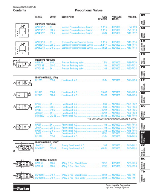
Catalog HY15-3502/USProportional Valves ContentsParker Hannifin CorporationPV1Proportional Control ValvesCatalog HY15-3502/USTechnical TipsParker Hannifin CorporationINTRODUCTIONThis technical tips section is designed to help familiarize you with the Parker line of Proportional Valves. In this section we present common options, technical terms, as well as a brief synopsis of the operation and applications of the various products offered in this section. The intent of this section is to help you in selecting the best products for your application.Seals: The majority of the products are available in Nitrile or Fluorocarbon Seals. The Winner’s Circle products feature a standard 4301 Polyurethane“D”-Ring. The “D”-Ring eliminates the need for backup rings. You should match the seal compatibility to the temperature and fluid being used in your application.Overrides: Overrides are standard on many of the Parker proportional valves. The override is generally a push type that is flush with the end of the tube. Consult the individual catalog pages for more details.TECHNICAL TERMSTo help in applying our proportional valve line of product, we have listed some technical terms below,as well as some helpful hints in applying our valves.Ohm’s Law: Electrical current is generated as a result of the relationship between input voltage and the resistance to the flow of electrical current. It is represented in equation form by I = V/R (or V=IR),where I is current, V is voltage and R is resistance.This is an important relationship to remember when dealing with any electrically operated valves.Proportional valves allow varying control of flow or pressure, dependant on the current signal provided.As coils heat up, their resistance rises. This means a higher voltage must be available to maintain the same amount of pressure or flow. Thus, the application needs to be designed such that the full on position is about 70% of the initial current draw. On the individual catalog pages a maximum control current is specified to help in applying our proportional valves.PWM: Pulse Width Modulation (PWM) is the preferred signal for controlling electrical current. PWM is on / off voltage in a square wave form. The percent “on” time or duty cycle provides the average voltage. The valve driver adjusts the duty cycle to obtain current control.We recommend valve drivers with current control for optimum performance. PWM signals also usually provide dither for the proportional valve. Dither is asmall back and forth movement of the valve spool around its set position. This rapid movement reduces the friction of the valve and leads to faster, more accurate response.PWM Frequency: The frequency of a PWM signal is the rate at which the signal is turned on and off.Parker’s analog proportional valves are designed to work with low frequency responses between 100-400Hz. The performance curves on our catalog pages were performed with a PWM signal at 200 Hz.Hysteresis: Due to various factors, the performance of a proportional valve will show a slightly differentperformance when the current signal is increasing than it will when the signal is being decreased. This difference is usually expressed as a percentage of total input change and is referred to as the hysteresis of the valve.Deadband: Cracking or deadband refers to theamount of the control signal that is needed to produce any movement of the spool. Thus, a 20% deadband means that 20% of the control signal is needed before the spool will move.COMMON OPTIONSAs you will see, Parker offers a variety of Proportional Valve products. As such, some of the options mentioned below may not be available on all valves. Consult the model coding and dimensions for each valve for specifics.Here are some of the common options available.Catalog HY15-3502/USProportional Control Valves Technical TipsParker Hannifin CorporationPV2PV3Proportional Control ValvesCatalog HY15-3502/USTechnical TipsParker Hannifin CorporationCatalog HY15-3502/USProportional Control Valves Technical TipsParker Hannifin CorporationPV4PV5Proportional Control ValvesCatalog HY15-3502/USTechnical TipsParker Hannifin Corporation。
液压泵使用说明书

液压泵使用说明书 The latest revision on November 22, 2020液压泵站目录第一章一般说明1-1 前言1-2 液压站出厂保证第二章液压站的运转2-1 液压站运转前的注意事项2-2 液压站的运转说明及注意事项第三章系统的结构3-1 液压系统的结构3-2 电气系统第四章液压站的常见故障处理及维护保养4-1 常见故障诊断与排除4-2 易损件明细表第一章一般说明1-1 前言本说明书就系统的组成、参数和功能操作及常见故障加以说明。
一般说来液压系统大部分的故障和事故,通过制定的维修方案也就是定期维护是可以预防和避免的。
所以本厂建议用户根据此说明书制定适合该套系统的维修计划,进行定期的维护以减少故障停机。
1-2本厂对液压站出厂后的质量保证我厂提供的液压系统总成,在产品交验一年内发生的故障,经确认责任在我厂的,我厂将负全部责任,进行免费维修或调换。
但对于以下的几种情况,我厂不负任何责任。
1)用户擅自更改超载保护装置的场合。
如,用户超载使用而造成的故障及元件的损坏由用户自己负责。
2)用户对液压系统使用方法不当的场合。
如,以后对过滤器修理检查后,漏装过滤器滤芯。
3)由于系统液压油在劣化状态下使用而造成的事故由用户自己承担责任。
4)不经我厂同意,擅自分解拆装油泵、控制阀、电动机等零部件而造成的损失本公司不承担任何责任。
5)因不可抗拒的自然因素带来的损坏。
6)下列消耗品亦不属于保证系列:密封件、工作介质、滤芯等易耗品不属于保证系列内的对象。
第二章液压系统的运转2-1 运转前的确认事项a)确认油箱工作油的液位;b)检查连接控制板上的主开关;c)检查过滤器的清洁度,如有必要,可更换;d)检查控制装置是否有报警信号,如有必要,复位存在的信号。
2-2液压站的运转说明及注意事项准备工作完成后,请按以下程序进行操作:a)合上主电源开关;b)按下电源控制按钮;c)按下工作需要开启泵;d)系统处于无人监控状态时,必须停机。
液压系统使用说明书
液压系统型号:YZL-10-160C-GX-00使用说明书扬州中茂液压机械有限公司2013年6月一、概述该液压系统采用高质量液压元件,具有操作方便、动作可靠、综合能力强、便于维护、保养等特点。
符合国标GB3766-1983《液压系统通用技术条件》中的各项技术条件二、技术参数:1、液压系统额定压力14Mpa2、系统最大流量18L/min3、电机功率5.5KW; n=1450r/min; 电压=380V/50Hz4、邮箱容积0.16m3三、液压原理图(见附图)四、液压系统安装说明1、产品运抵施工现场后,打开包装,仔细检查各部分是否满足合同供货要求,有无损坏现象,否则应及时与生产厂家联系。
2、液压系统和液压缸油口及其它外露口堵盖及包扎物在设备配管前不得脱落,以免对液压系统造成污染。
3、按液压系统原理图正确安装及配管,注意接口和配管密封的清洁。
钢管焊接时焊后需去除氧化皮,并进行酸洗和清洗。
4、液压缸与机架的联接罗栓必须紧固可靠。
五、调试1、安装完毕后应首先确认液压系统有无被污染的地方。
确认没有污染后再进行加油,加油时为防止污染应将液压油用滤油机过滤后,再经过空滤器滤网进行加油,切不可将空滤器滤网卸下加油。
2、加油完毕后将溢流伐手轮旋松(位置在阀块上方),点动电机,确认电机转向正确后,调整油泵调整罗钉。
(注意:油泵如长期闲置未用,重新启用时启动前必须通过泵回油口充满清洁的油液)3、一切正常后,启用电机旋转溢流伐手轮,观察压力表,先在低压下运行一段时间。
操纵电器箱按钮使液压缸缓慢往复运动几次排除系统内空气,并调整溢流伐使液压系统处于正常压力状态。
调整手柄正旋进,压力上升,调整手柄反旋出,压力下降。
4、调整集成块上的溢流伐使其达到所须的工作压力,但不可越过额定压力。
六、维护与保养1、使用中要经常保持设备清洁卫生,特别防止液压油的污染。
经常检查有无松动、漏油的地方,随时注意观察压力变化情况,检查电机、油泵的温度,发现问题及时处理。
Parker Hannifin 液压自动泵系统Check Valves手册说明书
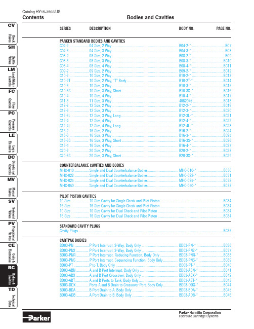
Bodies and CavitiesContentsParker Hannifin CorporationPARKER STANDARD BODIES AND CAVITIESC04-2....................04 Size, 2 Way.......................................................................B04-2-*...................................BC7C04-3....................04 Size, 3 Way.......................................................................B04-3-*...................................BC8C08-2....................08 Size, 2 Way.......................................................................B08-2-*...................................BC9C08-3....................08 Size, 3 Way.......................................................................B08-3-*.................................BC10C08-4....................08 Size, 4 Way.......................................................................B08-4-*.................................BC11C09-2....................09 Size, 2 Way.......................................................................B09-2-*.................................BC12C10-2....................10 Size, 2 Way.......................................................................B10-2-*.................................BC13C10-2T ..................10 Size, 2 Way, “T” Body.......................................................B10-2T-*...............................BC14C10-3....................10 Size, 3 Way.......................................................................B10-3-*.................................BC15C10-3S ..................10 Size, 3 Way, Short ............................................................B10-3S-*...............................BC16C10-4....................10 Size, 4 Way.......................................................................B10-4-*.................................BC17C11-3....................11 Size, 3 Way.......................................................................4082075................................BC18C12-2....................12 Size, 2 Way.......................................................................B12-2-*.................................BC19C12-3....................12 Size, 3 Way.......................................................................B12-3-*.................................BC20C12-3L ..................12 Size, 3 Way, Long.............................................................B12-3L-*...............................BC21C12-4....................12 Size, 4 Way.......................................................................B12-4-*.................................BC22C12-4L ..................12 Size, 4 Way, Long.............................................................B12-4L-*...............................BC23C16-2....................16 Size, 2 Way.......................................................................B16-2-*.................................BC24C16-3....................16 Size, 3 Way.......................................................................B16-3-*.................................BC25C16-3S ..................16 Size, 3 Way, Short ............................................................B16-3S-*...............................BC26C16-4....................16 Size, 4 Way.......................................................................B16-4-*.................................BC27C20-2....................20 Size, 2 Way.......................................................................B20-2-*.................................BC28C20-3S ..................20 Size, 3 Way, Short ............................................................B20-3S-*...............................BC29COUNTERBALANCE CAVITIES AND BODIESMHC-010...............Single and Dual Counterbalance Bodies................................MHC-010-*...........................BC30MHC-022...............Single and Dual Counterbalance Bodies................................MHC-022-*...........................BC31MHC-025...............Single and Dual Counterbalance Bodies................................MHC-025-*...........................BC32MHC-050...............Single and Dual Counterbalance Bodies................................MHC-050-*...........................BC33PILOT PISTON CAVITIES10 Size...................10 Size Cavity for Single Check and Pilot Piston...................................................................BC3416 Size...................16 Size Cavity for Single Check and Pilot Piston...................................................................BC3410 Size...................10 Size Cavity for Dual Check and Pilot Piston......................................................................BC3416 Size...................16 Size Cavity for Dual Check and Pilot Piston......................................................................BC34STANDARD CAVITY PLUGSCavity Plugs ..........................................................................................................................................................BC35CARTPAK BODIESBD03-PN ...............P Port Interrupt, 2-Way, Body Only .......................................BD03-PN-*............................BC36BD03-PN2.............P Port Interrupt, 2-Way, Body Only .......................................BD03-PN2-*..........................BC37BD03-PNR.............P Port Interrupt, Reducing Function, Body Only ...................BD03-PNR-*..........................BC38BD03-PNS .............P Port Interrupt, Sequencing Function, Body Only................BD03-PNS-*..........................BC39BD03-PT................P to T, Body Only...................................................................BD03-PT-*.............................BC40BD03-ABN .............A and B Port Interrupt, Body Only.........................................BD03-ABN-*..........................BC41BD03-ABX .............A and B Port Crossover, Body Only.......................................BD03-ABX-*..........................BC42BD03-ABT..............A and B Ports to Tank, Body Only..........................................BD03-ABT-*..........................BC43BD03-DDX.............Ports A and B Drain to Crossover Port, Body Only................BD03-DDX-*..........................BC44BD03-BDA .............B Port Drain to A, Body Only .................................................BD03-BDA-*..........................BC45BD03-ADB .............A Port Drain to B, Body Only .................................................BD03-ADB-*..........................BC46SERIESDESCRIPTIONBODY NO.PAGE NO.Bodies and Cavities ContentsParker Hannifin CorporationSERIES DESCRIPTION BODY NO.PAGE NO.SPECIAL BODIES AND CAVITIESCAV0W-2...............2 Port....................................................................................LB1079*................................BC47 CAVSW-3...............3 Port....................................................................................LB1081*................................BC48 CAVT11A...............3 Port or 4 Port Dual.............................................................LB1082*................................BC49 CAVT21A...............4 Port....................................................................................LB1083*................................BC50 2C..........................2 Port....................................................................................LB1021*................................BC51 2G..........................2 Port....................................................................................LB1032*................................BC52 2R..........................2 Port....................................................................................LB105**................................BC53 2U..........................2 Port....................................................................................LB102**................................BC54 2X..........................2 Port....................................................................................LB1051*................................BC55 3A..........................3 Port....................................................................................LB100**................................BC56 3C..........................3 Port or 4 Port Dual.............................................................LB100**................................BC57 3J..........................3 Port....................................................................................LB1009*................................BC58 3K..........................3 Port....................................................................................................................................BC59 3M.........................3 Port or 4 Port Dual.............................................................LB100**................................BC60 3X..........................3 Port....................................................................................LB1055*................................BC61 3Z..........................3 Port....................................................................................LB103**................................BC62 4C..........................4 Port....................................................................................LB1056*................................BC63 5A..........................5 Port....................................................................................LB103**................................BC64 53-1.......................3 Port or 4 Port Dual.............................................................LB1031*................................BC65 54-1.......................3 Port....................................................................................LB10591................................BC66 68-1.......................3 Port or 4 Port Dual.............................................................LB102**................................BC67 91-1.......................3 Port....................................................................................LB1015*................................BC68 100-1.....................5 Port....................................................................................LB1031*................................BC69BC1Bodies and CavitiesCatalog HY15-3502/USTechnical TipsParker Hannifin CorporationBC2Catalog HY15-3502/USBodies and CavitiesTechnical TipsParker Hannifin Corporation COMMON OPTIONS & FEATURES (Cont.)Pressure Drop: The pressure drop through a line body is fairly minimal. Each catalog page shows a pressure drop curve. This should be added to the pressure drop through the cartridge when trying to estimate total pressure drop for a function.Porting: Parker offers a variety of port sizes and types for each line body. While NPT or pipe ports were once very popular and are still offered, we recommend SAE ports for new applications. SAE ports and fittings provide a more secure connection than pipe ports.BSPP ports are also available.Port Numbering Change: With this catalog, we have re-numbered the ports on our 3-way line bodies. In the past, three way bodies were numbered with the nose231321Previous Design Current Designbeing port 1, the middle port labeled (3), and the top port labeled (2). Over the years, this has caused some confusion, so we have relabeled the ports sequentially from the bottom. For identifi-cation, the current design will be marked with a Parker symbol like the one shown.CAVITIESThe hole that the cartridge valve is screwed into is called a cavity. Many cartridge producers manufacture valves that fit a “common” cavity. With a “common” cavity, a valve theoretically could be removed from a cavity and replaced by another manufacturer’s product. One should be careful though to check cross drill ports and thread depths when pursuing this activity. While it is true that many manufacturer’s products fit inside another’s cavity,the cross drills sometimes expose an o-ring to pressure, causing the o-ring to be extruded.Valve / Cavity Compatibility Chart: Through acquisition, Parker Hannifin has accumulated anumber of manufacturers with “common” cavities. To accommodate all of our product lines, we havereleased a new cavity for our Winner’s Circle product line. The cavities shown in this catalog are considered Winner’s Circle Cavities. The Winner’s Circle valves are downward and upward compatible with the Parker Series of product. On each catalog page, you will find a chart like the one shown on this page. The purpose of this chart is to help identify if a valve from one acquisition can be replaced by the Winner’s Circle valve, or another acquisition. The valves are designated by the columns of the chart and thecavities by the rows. If you have an existing cavity, you find it on the chart and follow across to see which valves you may put in the cavity. For instance, using the chart below, let’s say you have an existingmanifold in which you had manufactured a FPS cavity (maybe you were using a SV2A-10). By finding the row labeled FPS and following across, you find that you could use the new Winner’s Circle product, an FPS product, or a CEC product of the same size in this cavity. A Parker or Waterman valve will not fit in this cavity without modifying the cavity. This chart is provided to help you in converting to the Winner’s Circle product line.Cavity Tools: On each catalog page, cavity tools are listed for your use in creating special manifolds. More is discussed on manifold construction in the Technical Data section of this catalog. For 3-way and 4-way valves, you will find a roughing and a finishing tool.The rougher is a step drill used to prep the cavity for the finishing tool. The rougher removes the mass of material and is necessary because the finisher is not designed for primary forming. The finisher is aprecision tool used to provide the final dimensions of the cavity. No rougher is offered for 2-way cavities because a standard drill bit can be used to remove the mass of material.Winner’s Circle X X X X XParker X X X Waterman X XXFPS X X X CECXXXW i n n e r ’s C i r c l eP a r k e rW a t e r m a nF P SC E CVALVEC A V I T YBC3Bodies and CavitiesCatalog HY15-3502/USTechnical TipsParker Hannifin CorporationBC4Catalog HY15-3502/USBodies and CavitiesTechnical TipsParker Hannifin CorporationBC5Bodies and CavitiesCatalog HY15-3502/USTechnical TipsParker Hannifin Corporation。
MGE-Planet 3000 UPS 操作手册

2. UPS 概述
6
2.1 拓扑布局.............................................................................................................................................. 6 2.2 系统说明.............................................................................................................................................. 8
2.2.1 整流器 ................................................................................................................................................8 2.2.2 12 脉冲整流器 (选件) .........................................................................................................................8 2.2.3 逆变器 ................................................................................................................................................9 2.2.4 电池充电器 .........................................................................................................................................9 2.2.5 静态旁路.............................................................................................................................................9 2.2.6 手动旁路.............................................................................................................................................9 2.2.7 前面板 ................................................................................................................................................9 2.3 运行状态............................................................................................................................................ 10 2.3.1 正常运行...........................................................................................................................................10 2.3.2 因逆变器故障而由旁路向负载供电...................................................................................................10 2.3.3 整流器失效或交流电源失效..............................................................................................................11 2.3.4 手动旁路...........................................................................................................................................11
parker柱塞泵说明书

Parker柱塞泵说明书1. 引言本说明书将介绍Parker柱塞泵的结构、工作原理、安装方法以及维护保养等相关内容。
Parker柱塞泵是一种高效、可靠的液压传动装置,广泛应用于工程机械、农业机械、船舶等领域。
2. 结构和工作原理Parker柱塞泵主要由驱动轴、轴承、柱塞组件和油箱等部分组成。
其工作原理是通过驱动轴带动轴承旋转,使得柱塞随之运动,从而产生压力差,将液体从低压区域吸入,再通过高压区域输出。
3. 安装方法3.1 准备工作在安装Parker柱塞泵之前,需要先进行准备工作。
首先,清洁安装位置,并确保其平整度符合要求。
其次,检查传动部件是否完好无损。
3.2 安装步骤1.将Parker柱塞泵放置在安装位置上,并与传动轴对齐。
2.使用螺栓将Parker柱塞泵固定在安装位置上,确保固定牢固。
3.连接油管,确保连接紧密,无漏油现象。
4.检查安装是否正确,并进行必要的调整。
4. 维护保养为了确保Parker柱塞泵的正常运行和延长其使用寿命,需要进行定期的维护保养工作。
4.1 润滑定期检查润滑油的情况,并根据需要添加或更换润滑油。
同时,注意清洁润滑系统,防止杂质进入。
4.2 清洗定期清洗Parker柱塞泵及其周围环境,防止灰尘和杂物对其造成损害。
4.3 检查检查Parker柱塞泵各部件是否正常运转,如有异常情况及时修复或更换。
4.4 注意事项•在维护保养过程中,请务必断开电源并等待其冷却后再操作。
•使用适当的工具和设备进行维护保养,并遵守相关安全操作规程。
•如需更换零件,请选择原厂配件或经过认证的替代品。
5. 故障排除在使用Parker柱塞泵时,可能会遇到一些故障情况。
下面列举一些常见故障及其排除方法:5.1 漏油可能原因: - 油封磨损 - 油管连接不紧密排除方法: - 更换磨损的油封 - 确保油管连接紧密5.2 压力不稳定可能原因: - 柱塞组件磨损 - 泄漏排除方法: - 更换磨损的柱塞组件 - 检查并修复泄漏点6. 注意事项在使用Parker柱塞泵时,请务必遵守以下注意事项:•请勿超过Parker柱塞泵的额定工作压力范围。
Parker Hannifin 低高度容器系列 V-Pak 流量控制电源单元说明书

Low Profile Tank Size Pump FlowElectrical MotorsMaximum V-PakLiters (Gallon)LPM (GPM) @ 1800 RPMKW (HP)BAR (PSI)V8302.8 (80)136.7 (36.1)5.6 - 30 (7 1/2 - 40)207 (3000)Quick Reference Data ChartPUMP COMPENSA TOR CONTROLSINGLE REMOV-ABLE TOPPLATEGL YCERINE FILLEDPRESSURE GUAGE WITH SHUT -OFF VALVE PUMP CASE PREFILL PORT PRESSURE PORTRETURN PORT SAE-12 RESERVOIR DRAINSAFETY RELIEF VALVEStandard Features•Vertical Design •Submerged Pump•Precision Pump Mounting Adapters •Suction Strainer•Glycerine Filled Pressure Gage with Shut Off •Oil Level Gage with Thermometer •Remote Compensator and Safety Relief •Breather and Fill Cap •1800 RPM Motor •Drain Plug •Clean Out Cover•Single Removable Topplate •Extra SAE-20 Return Port•All Hydraulic Connections SAE Straight ThreadBenefits•Saves Floor Space •Positive Pump Inlet •Longer Pump Life•Protects Pump from Contamination •Improved Diagnostics•Helps to Maintain Trouble-Free Performance •Protects Against System Shock•Easy to Fill Tank, Control Ingression of Airborne Contaminants •More Flow at Less Cost •Allows Drainage of Fluid•Easy Access to Inside of Reservoir •Easy Servicability of Internal Components •Allows Flexibility for Customer Return Plumbing •No LeaksFILLER/BREATHEROIL LEVEL GUAGE WITH THERMOM-ETER406mm (16")CLEANOUT COVERSeries V-PaksPRESSURE SWITCHTEMP/LEVEL SWITCHMULTI-ST ATIONMANIFOLDRETURN FILTER HEA T EXCHANGERPRESSURE FILTER TEMP . SWITCHEXAMPLE OF VARIOUS ACCESSORIES INSTALLED FOR REFERENCE ONL YAccessory OptionsSCHEMATIC - BASIC UNIT WITH ACCESSORIESBREATHERNMHYDRAULIC SCHEMATICTR*L KH PSEE MANIFOLDOPTIONSSEECOMPENSATOR OPTIONSX SAE-12MA B OPTIONMC OPTIONMSEECOMPENSATOR OPTIONSSEECOMPENSATOR OPTIONSOption A Cooling Loop (0.6 KW (0.8 HP) Removal)Option B Cooling Loop (1.1 KW (1.5 HP) Removal)Option C System Cooling/Filter Loop (3.4 KW (4.5 HP) Removal)Option H Pressure Filter Option K Pump Outlet Check ValveOption L Bypass Check-Return Ht. Ex. Only Option N Return Filter - Dual ElementOption R*Combination Level/Temperature SwitchSeries V-PaksL A V O M E R T A E H A N O I T P O )*P H 08.(W K 6.LA V O M E R T A E H BN O I T P O )*P H 5.1(W K 1.1Dimensions - AccessoriesV8 reservoir with "Omit" manifold shownInch equivalents for millimeters dimensions are shown in (**)Ordering Note: Units with PVP76 pumps and requiring options "A", "B" or "C" can only be ordered withV8 (302.8 L/80 Gal.) reservoir.Technical InformationOption "A" Cooling Loop5.6 KW - 18.6 KW (7.5 HP - 25 HP) ONLYOption "B" Cooling Loop*Performance data are based on 100SSU oil leaving the cooler 4°C (40°F) higher than the ambient air temperature used for cooling.(3.38)85.9(5.11)129.8Series V-PaksL A V O M E R T A E H C N O I T P O )*P H 5.4(W K 4.3*Performance data are based on 100SSU oil leaving the cooler 4°C (40°F) higher than the ambient air temperature used for cooling.Option "C" System Cooling/Filter LoopDimensions - AccessoriesV8 reservoir with "Omit" manifold shownInch equivalents for millimeters dimensions are shown in (**)Ordering Note: Units with PVP76 pumps and requiring options "A", "B" or "C" can only be ordered withV8 (302.8 L/80 Gal.) reservoir.Technical Information(16.35)415.3Series V-Paks Installation InformationOperating Notes•Jog the electric motor once and verify that the electric motor is rotating in the same direction as the arrow on the electric motor housing. If direction is incorrect, reverse two of the three leads on a 3-phase electric motor.•V-Pak power units are tested and pressure control valves are factory preset. If adjustments are needed, follow the procedure below: Begin adjusting relief valve and pump compensator control valve to increase pressure gradually. (NOTE: Always set relief valve 28-31 bar (400-450 psi) higher than pump compensator pressure control valve or severe overheating will occur.)•If pump fails to prime, vent pump discharge to atmosphere to establish fluid flow.•Reservoir temperature should not exceed 66°C (150°F). System reliability and component service life will be reduced when system is operated at higher temperature.•Clean fluid = improved system reliability and longer component service life, change filter elements whenever filter indicators indicate a dirty element condition.•It is recommended that every 4,000 operating hours or once a year, whichever occurs first, the filler/ breather cap and suction strainer should be replaced.Fluid RecommendationsPremium quality hydraulic oil with a viscosity range between 150-250 SSU (30-50 cst.) at 38°C (100°F). Normal operating viscosity range between 80-1000 SSU (17-180 cst.). Maximum start-up viscosity is 4000 SSU (1000 cst.).NOTE: Consult Parker when exceeding 71°C (160°F) operation. Oil should have maximum anti-wear properties, rust and oxidation treatment. FiltrationFor maximum pump and system component life, the system should be protected from contamination at a level not to exceed 125 particles greater than 10 microns per milliliter of fluid. (SAE Class 4 / ISO 16/ 13.) Due to the nature of variable displacement pumps, variations in pump inlet conditions, fluid acceleration losses, system aeration, and duty cycle must be carefully considered before specifying suction line filtration. Contact your Parker representative forassistance.Series V-Paks。
Parker Hannifin 流动系统汽油泵扭流控制系统指南说明书

Mineral-based or synthetic with lubricating properties at viscosities of 45 to 2000 SSU (6 to 420 cSt)
ISO Code 16/13, SAE Class 4 or better
.32 kg (0.7 lbs.)
C12-2 (See BC Section for more details)
Rougher None Finisher NFT12-2F
Performance Curves
Pressure Drop vs. Flow @ 100% Control Current
PSI Bar
Hydraulic Oil 150 SSU @ 100°F (32 cSt)
Code Body Material Omit Steel
A Aluminum
Code Port Size Body Part No. 12P 3/4″ NTPF (B12-2-*12P) 8T SAE - 8 (B12-2-*8T) 12T SAE - 12 (B12-2-*12T) * Add “A” for aluminum, omit for steel.
CV
Check Valves
See DS Coil 1" I.D. Information For Terminal Connectors
Finger Tight
Torque
48.0 (1.90)
1-1/4" Hex. 29 Nm (21 lb. ft.) Torque
1-1/16 - 12 UNF-2A Thread
Solenoid Valves
高效液相色谱戴安U-3000操作手册-1

U-3000操纵手册之勘阻及广创作1.操纵条件:电压:220V, 温度:10-40℃,湿度:10%-85%。
μμm过滤(色谱纯除外)并脱气。
3.若流动相含有无机盐或酸,每天仪器使用完后,要用5%:95%的甲醇/水清洗系统至少30min后再用100%甲醇冲30min关机。
开机则用5%:95%的甲醇/水冲10min,换流动相。
先开仪器电源,再开电脑,待电脑右下角的服务器监测器由黄色变成灰色,双击面上的图标,进入工作站,如图为工作站根目录,点击快捷栏内的“default panel tabset”出现以下界面,点开“”My Computer”前加号:选择“Chromeleon Server”,“OK”,出现下面的控制界面,分别在“Pump”下设置比例和流速如果流路内有气泡,拧松泵混合器上的“Purge”阀,点上图内的“Purge off”前的按钮,快速排气泡,待气泡排完后,上图内的“Purge off”前的按钮停止,拧紧“Purge”阀,在“Col.Comp”下设置柱温,在“VWD”下开氘灯,设置波长。
系统开始平衡,点快捷栏内的兰色圆点“”收集基线,待基线稳定后,点“”停止收集基线,准备测样。
新建文件夹(第一次使用必须)点快捷栏内“”,回到根目录,右键点击根目录,,点“New Directory”,输入文件夹名称,“OK”。
建立程序文件点“File”下“New”,“OK”,“下一步”,设置温度,“下一步”,设置流速和各通道比例,“下一步”,设置取样和推样速度,“下一步”,设置收集时间,选择收集信号,“下一步”,“下一步”,“下一步”,设置波长,“下一步”,“完成”,如需要,可更改一些参数后,点右键,选“Check”,“确定”,点快捷栏内的“”,选择保管路径,输入名称后“Save”,关闭窗口。
新建方法文件点“File”下“New”,点“File”下“Save As”选择保管路径,输入名称后“Save”,关闭窗口。
- 1、下载文档前请自行甄别文档内容的完整性,平台不提供额外的编辑、内容补充、找答案等附加服务。
- 2、"仅部分预览"的文档,不可在线预览部分如存在完整性等问题,可反馈申请退款(可完整预览的文档不适用该条件!)。
- 3、如文档侵犯您的权益,请联系客服反馈,我们会尽快为您处理(人工客服工作时间:9:00-18:30)。
国电联合动力技术有限公司
3MW风机液压系统使用说明书
Engineering Document Doc No.: PHBJ-IM-10052-A0-0-SH
1. 范围
本操作说明书适用于国电联合动力技术有限公司3MW风机液压系统使用说明书(以下简称系统); 本操作说明书规定了系统的使用方法,常规保养和常见故障的处理方法。
2. 系统简介
本系统主要用于3MW风机的转子刹车,偏航刹车和主轴插销控制。
2.1 系统组成
本系统由液压动力站总成和管道组成。
2.2 主要工作参数:
2.2.1 主齿轮泵: PGP502A0012CH1H1NE3E2B1B1 (1.2ml/r)
最大工作压力: 25 MPa
数量: 1台
辅应急手动泵: HP10-21A-O-N-B(10.6ml/stroke)
2.2.2 电动机
电机型号: MS802-4-B14-400/50-IP55
输出功率: 0.75 KW
转速: 1500 rpm
数量: 1台
2.2.3 电加热器
型号: SK7787-220-170
功率: 170W 220VAC 50Hz
数量: 1 台
2.2.5 供电要求
电动机为:三相 AC400V, 50Hz
电加热器: 单相 AC220V, 50Hz
控制电源和电磁铁电源为: DC24V
2.2.6 油箱容积
有效容积为12L,最大容积为15L。
2.2.7 液压工作液
Mobil SHC 524油液清洁度应保持在NAS 8级(ISO 17/14),最低不能超
过NAS9级( ISO 18/15),油液含水量不超过0.1%。
2.3 外形及安装说明
外形, 外接管路及地脚螺钉尺寸见所附外形图
3. 工况说明:
系统液压回路及相关的技术参数见液压系统原理图和附件样本。
系统由电机泵组(6,7,8)提供动力, 系统压力由溢流阀(13.1)调整至170bar,
蓄能器(22,23)提供应急动力源, 压力传感器(19.3)监控主系统压力, 压力
传感器(19.2)监控偏航刹车压力, 压力传感器(19.1)监控主轴刹车压力,节
流阀(24)平时处于关断状态, 在泵卸荷时才需要开启.
3.1 转子制动回路
转子制动器系统用来停止转子。
正常工作时, 电磁换向阀(15.1,27.1)电磁铁Y1,Y2得电, 转子刹车释放.
应急情况下, Y1, Y2失电, 蓄能器(23)压力油经电磁阀(15.1)进入刹车卡
钳, 转子制动. 压力继电器(3.8)在刹车油腔低于10bar时断开发讯. 压力
传感器(19.3)监控蓄能器(23)充压情况. 压力传感器(19.1)监控转子刹车
压力情况.减压阀(16)控制刹车油最高压力. 节流阀(17.1)控制刹车起压时
间.
3.2 偏航刹车回路
偏航制动器系统用来停止机舱旋转。
电磁换向阀(27.2)得电, 偏航刹车释放. 电磁换向阀(27.3)得电, 偏航
刹车半刹, 溢流阀(13.3)调整半刹时的压力. 节流阀(17.2)控制刹车起压时
间.电磁换向阀(15.2)在偏航半刹和解缆时得电。
3.3 主轴插销回路
主轴插销回路是用来在停机后防止主轴在外力作用下继续旋转。
手动泵(11.2)用于给主轴插销油缸加压,手动换向阀(26)控制压力油的
流向,以控制主轴插销油缸伸出或者缩回。
3.2 使用条件说明
3.2.1 液位:工作油路液位应保持在油箱高度的70%左右。
油箱上设有液位液温控制器,当液位低时,SL液位控制器断开,提示使
用人员加油。
3.2.2 油温:油温要求控制在2℃和70℃之间;
当油温低时,加热器自动启动;
当油温高于700C时,油温控制器ST断开,高温报警.
3.2.3 压力:系统主轴刹车压力由S1,BP1,BP2和BP3监控, BP1输出为
4~20mA(0~250bar)信号,对应应急动力源压力,S1监控刹车压力, 低于
10bar时断开. BP2输出为4~20mA(0~250bar)信号,对应应监控高速轴刹
车压力,偏航刹车压力由BP3监控, 输出为4~20mA(0~250bar)模拟信号.
4. 故障排除:
4.1 系统存在较大的噪声
4.1.1 溢流阀啸叫
逆时针调整系统溢流阀(13.1), 降低系统压力, 故障排除后将压力重新调
整至160bar
4.1.2 减压阀震动
调整减压阀(16),稳定主轴刹车压力
4.1.3 节流阀节流嘶叫
检查节流阀(24), 逆时针松开后, 再顺时针拧到底关死.
4.1.4 泵吸空噪音
将系统阀块拆下来, 然后检查齿轮泵吸口管路是否松动.
4.1.5 机械振动
电动机泵组轴对中不佳或联轴器松动重新对中或固紧联轴器
管道振动固紧管道或重新安装
液压泵故障或损坏修理或更换
压力阀不稳定 (振荡) 重新设置正确或更换合适的压力阀
4.2 启动后无压力或压力不足
4.2.1 检查电气信号, 电磁铁Y2,Y3,Y4,Y5是否已经断电
4.2.2 检查电机转向是否正确(电机风扇为顺时针旋转)
4.2.3 检查油箱油位是否正常.
4.2.4 节流阀24松动, 逆时针旋转拧紧.
4.2.5 调整溢流阀13.1, 逆时针旋转增加压力.
4.2.6 逆时针调整节流阀17.1 如果压力上升, 则电磁换向阀1
5.1或者14.2卡
死, 更换.
4.2.7 检查压力传感器19.3是否接线正确, 工作是否正常.
4.2.8 液压泵吸油不正常吸口管道漏气.
4.3 主系统不能保压
4.3.1 节流阀24松动, 逆时针旋转拧紧.
4.3.2 电磁换向阀1
5.1没有得电. 保压状态下电磁阀15.1需要得电.
4.3.3 检测蓄能器23充气压力是否正常
4.3.4 检查电磁阀27.2和27.3, 是否卡死或者堵塞. 针对这个故障, 可以通过关
闭针阀17.2, 如果系统保压正常, 则可以判断确实为电磁阀问题.
4.4 主轴压力不能保压
4.4.1 电磁换向阀1
5.1是否已经断开
4.4.2 单向阀14.2故障, 可以通过拧紧17.1, 看保压是否正常来判断.
4.4.3 蓄能器18充气压力是否正常
4.4.4 电磁阀27.1是否已经得电
4.5 半刹压力不正常
调节溢流阀13.3 调整到指定值.
如遇到无法修复之故障,请与设备供应商联系。
5 维修保养手册
5.1 日常检查
5.1.1 液压站外观正常,无明显移动和碰擦痕迹。
5.1.2 油箱油位是否在正常位。
5.1.3 油泵吸口球阀是否打开。
5.1.4 电气接线正常,无松动。
5.1.5 系统压力是否稳定和在规定范围内有无异常。
5.1.6 油温是否正常,一但超过70℃,应立即停机检查。
5.1.7 系统各连接点是否有漏油。
5.1.8 留意滤器堵塞报警信号并及时更换滤芯。
5.2 月检查
5.2.1 定期紧固各连接点接头和螺钉。
5.2.2 检查连接点是否漏油,更换受损密封件。
5.2.3 检查过滤器和空气滤清器,定期清洗和更换。
5.2.4 检测系统油液质量,注意污染和乳化现象。
5.2.5 清理液压站和管路,保持站内外环境整洁。
5.3 年检
5.3.1 每半年取样油液,按油料化验单化验并归档.
5.3.2 针对化验不合格的系统,应更换系统油液,之前应清洗整个系统的管路和
油箱。
原则上每18个月应更换一次系统油液。
5.3.3 在规定工况下检测泵,阀,马达,油缸等元件的性能,及时更换受损元件。
5.3.4 每2年更换所有系统的密封件。
在日常使用时应注意以下环节:
1. 液压油应保持绝对清洁,应经常清理油箱和管路,注意液压系统管路和油箱防水,防尘,防锈,注意保持油箱加油口,空滤口,管路接入点的清洁。
2. 更换油液或新增的油液必须符合本系统规定的油液牌号,新增油液的牌号必须与正在使用的油液牌号一致,并经过化验,符合规定的标准。
3. 更换油液时,新加油液必须经过滤达到规定才能加入系统循环。
如果需更换油液牌号,应注意将原有系统中所有油液清空,包括油箱,管路和油缸中的油液。
4. 清洗油箱,泵,阀时,应极力避免污染物,包括纤维和油泥等进入液压系统。
