UT230C功率计说明书(高清)
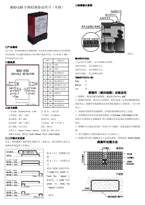
BOO-230车辆检测器说明书
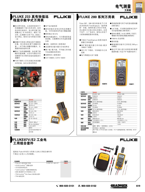
(图 2)
探测环布置方法一
长方型:适合汽车和货车的检测
探测环的长度与圈数:
尺寸 1.5m x 1m 2.0m x 1m 2.5m x 1m 3.0m x 1m
圈数 6 6 6 5
尺寸 3.5m x 1m 4.0m x 1m 5.0m x 1m 6米以上
圈数 5 5 4 4
探测环布置方法二
菱形:适合电动单车和自行车的检测
情况二
探测环在不受控制的情况下自行开关或红色发光二极管常亮。 可能原因:接地线故障;第二探测环干扰;当物体在其表面移动时,
探测环移动 解决方案:与《闪动六次》之解决方案相同(参考第一页面板功能)。
如果输出继电器在开关时产生电感,这将会导致故障。当 这情形发生,必须使用干扰抑制器(例如22欧姆/0.1μH) 保护用户。 持续闪动: 可能原因:功能开关设定不正确 解决方案:切断电源,移开壳子,更正功能开关关设定。 闪动两次或四次: 可能原因:探测环太大或太小,绕组(探测环电磁量:测量理想数据 为80至300μH) 解决方案:1、更换探测环(减少或增加绕组数目)。 2、重新校准,更改敏感度开关,等大约 3 秒,然后将敏 感度开关改回原先设定,或暂时切断电源约 5 秒后重启
探测环布置方法三
“8”字形:此电环有较低横向灵敏度,适合安装在非常靠近闸门的地方或容易 受横向干扰的场合。如轨道车道旁和自动伸缩门等。
安装备注
1、尽量选择最短的电环连接线,同时将之与任何输电线分开。 与输电线之间的平行距离必须超过10公分,不同探测器之间的电环连 接线也必须保存距离。两边的连接线必须由控制箱开始直至探测器每 米扭绞过20次。连接线不可以超过相邻电环的槽沟,同时必须保护以 确保不受机械损坏。
储存温度:-40℃~+85℃
【推荐】功率计作业指导书-优秀word范文 (8页)

本文部分内容来自网络整理,本司不为其真实性负责,如有异议或侵权请及时联系,本司将立即删除!== 本文为word格式,下载后可方便编辑和修改! ==功率计作业指导书篇一:WT3000功率计操作指引321.目的正确使用仪器,保证测试结果的科学性、正确性、准确性,以及保障岗位作业人员的人身安全,完善部门管理制度。
2.范围2.1检测中心仪器设备操作人员。
3.技术参数3.1电压量程:0V-1000V; 3.2电流量程:0A-30A。
4.职责4.1检测员:负责日常保养与维护。
5.作业程序 5.1测量之前5.1.1连接好仪器供电电源,按“电源开关”开启仪器。
5.1.2量程设定电压和电流量程设定:先按“ELEMENT”键选择测量模块,根据被测产品的参数按“▲”键和“▼”键设定好相应测量模块的电压和电流量程,如不清楚电压和电流量程,请把电压和电流量程设定到最大值。
5.1.3模式选择按“MODE”键选择电压和电流模式,“RMS”为真有效值,“MEAN”为校准到有效值的整流平均值,“DC”为简单平均,“RMEAN”为整流平均值。
5.2测量连接“VOLTAGE”的两个接线柱接测量电压,“CURRENT” ”的两个接线柱接测量电流,“EXT”接电流互感器。
5.3按键功能5.3.1“WIRING”键:显示接线的设定菜单,用于选择接线方式,选择单独设定输入单元,设定效率公式,设定接线补偿,设定效率补偿等。
5.3.2“ELEMENT”键:选择要设定量程的输入单元,每按一次,被选输入单元切换一次。
5.3.3“AUTO”键:当AUTO指示灯点亮时,启用自动量程功能。
5.3.4“SHIFT+EXT SENSOR”键:显示用于设置每个输入单元的电流传感器换算比的菜单,用这些换算比可以将电流传感器输出转换成电流。
5.3.5“UPDATE RATE”键:显示数据更新率的设定菜单,用于选择决定电压,电流和功率等数值数据(测量值)的采样数据的捕获间隔(数据更新率)。
(最新整理)传输仪表2M表、光功率计使用方法

(最新整理)传输仪表2M表、光功率计使用方法(完整)传输仪表2M表、光功率计使用方法编辑整理:尊敬的读者朋友们:这里是精品文档编辑中心,本文档内容是由我和我的同事精心编辑整理后发布的,发布之前我们对文中内容进行仔细校对,但是难免会有疏漏的地方,但是任然希望((完整)传输仪表2M表、光功率计使用方法)的内容能够给您的工作和学习带来便利。
同时也真诚的希望收到您的建议和反馈,这将是我们进步的源泉,前进的动力。
本文可编辑可修改,如果觉得对您有帮助请收藏以便随时查阅,最后祝您生活愉快业绩进步,以下为(完整)传输仪表2M表、光功率计使用方法的全部内容。
常用传输测试仪表的使用方法及注意事项一、传输测试2M表(一)W ET-210B 2Mbit/s数字传输分析仪使用方法和应用举例2Mbit/s数字传输分析仪适用于数字传输系统的工程施工、工程验收、日常维护及科研测试。
1.面板说明POWER PATTERN FAS ERRSIGNAL AIS CRC ERRFRAME RA EBIT ERRMFRAME MRA PATSLIPCRC-4 CODE ERR BIT ERRHISTORY HISTORY HISTORYPOWER 电源工作状态指示.绿色表示正常工作;红色表示欠电压,需充电;橙色表示正在充电。
SIGNAL RX1端口或DATA端口信号状态指示。
红色表示无接收信号或不成环路状态。
FRAME RX1端口信号帧同步状态指示。
红色表示帧同步丢失。
MFRAME RX1端口信号复帧同步状态指示。
红色表示复帧同步丢失.CRC—4 RX1端口信号结构指示.红色表示有CRC-4校验码插入。
PATTERN RX1端口或DATA端口信号图案同步状态指示。
红色表示图案同步丢失。
AIS RX1端口或DATA端口输入信号告警指示.红色表示端口信号输入有告警.RA RX1端口输入信号远端帧告警。
红色表示远端帧丢失。
MRA RX1端口输入信号远端复帧告警。
230瓦 16CH 使用说明书

230W 摇头光束灯请在使用该产品前仔细阅读本产品的说明书请保存好产品说明书首先感谢您购买我们的专业灯光产品:本说明书包含如何安全地进行安装以及使用的重要信息,请仔细阅读后按要求进行安装和操作,同时请将此说明书妥善保存,以备不时之需。
此摇头灯是非常出色的人性化与工业设计的完美组合,造型美观、流畅。
灯体采用铝合金和耐高温工程塑料设计,具有良好的散热效果;传动机构采用电子定位技术,灯体采用超静音风扇散热,。
产品完全符合CE标准,采用国际标准DMX512信号控制。
广泛运用于电视台,迪士高,歌舞厅,夜总会等室内场所。
本手册如有技术改动,恕不另行通知。
1.技术参数电压:110V-230V 50-60HZ功率:380W灯泡:欧司朗输出功率:189W色温度:8000K光通量:7950LM寿命:2000小时放大角度:0-3.8度调焦:电子自动对调颜色系统:14个可换色片加白光流水效果图案系统:17个可换图案加白光高速抖动效果棱镜:八棱镜调光:0-100调光频闪:超快速度频闪通道:16CH显示:LCD液晶显示X轴:540度Y轴:270度灯体尺寸: 330X405X475净重: 16kgs毛重: 18kgs2.通道参数:Ch1: 水平0-255 0-450 °Ch2:垂直0-255 0-270 °Ch3:水平微调0-255 0-2.1 °Ch4:垂直微调0-255 0-1.0 °Ch5:水平垂直速度0-255 快-慢Ch6:雾镜0-255无-雾化Ch7:调光0-255 灭-亮Ch8:频闪0 关1-50 开51-240 频闪慢--快241-255 开Ch9: color0-8 白光8 to 15 颜色116-23 颜色224-31 颜色332-39 颜色440-47 颜色548-55 颜色656-63 颜色764-71 颜色872-79 颜色980-87 颜色1088-95 颜色1196-103 颜色12104-111 颜色13112-127 颜色14128-191彩虹效果正转快--慢192-255 彩虹效果反转慢--快Ch10:颜色效果0-127 整步进和调速128-255 微步进和调速Ch11:图案0-6 白光7-13 图案114-20 图案221-27 图案328-34 图案435-41 图案542-48 图案649-55 图案756-62 图案863-69 图案970-76 图案1077-83 图案1184-90 图案1291-97 图案1398-104 图案14105-111 图案15112-118 图案16119-127 图案17128-191 彩虹效果正转慢--快192-255 彩虹效果反转慢--快ch12: 图案震动0-255 0--400°ch13:调焦0-255 近--远ch14:棱镜0-31 无棱镜32-255 棱镜ch15:棱镜旋转0-127 角度128-191 正转快-慢192-255 反转慢-快ch16:灯泡控制100-105 延时关200-205 延时开0-254 无操作255-255 数秒后复位3.电脑操作菜单:(需要显示的主屏界面黑白图片128×48像素,或文字)DMX地址= /Address= xxx退出/Exit/DMX地址/Address/ DMX地址= /Address= xxx参数设置/Parameter --返回/back--控制模式/Control --标准模式/Standard--扩展模式/Extended--灯具型号选择/Model选项设置/option --返回/back--X 轴控制反转/x Reverse --否/No--是/Yes--Y 轴控制反转/Y Reverse --否/No--是/Yes--XY 轴交换/XY Exchange --否/No--是/Yes--调光通道反向/Dimmer Reverse --否/No--是/Yes--光圈通道反向/iris Reverse --否/No--是/Yes--效果轮转距离最短/turn shortest --否/No--是/Yes--允许dmx复位/Dmx reset --否/No--是/Yes显示设置/Display --返回/back--显示语言/Language手动控制/man Control --返回/back--ch1 0--255--ch2 0--255--ch3 0--255--ch4 0--255--ch5 0--255--ch6 0--255--ch7 0--255--ch8 0--255--ch9 0--255--ch10 0--255--ch11 0--255--ch12 0--255--ch13 0--255--ch14 0--255--ch15 0--255--ch16 0--255测试运行/Test operation --返回/back--声控/Sound --运行程序/program run--自动/Auto --运行程序/program run恢复出厂默认设置/Resume default --返回/back--确认/enter灯具复位/Fixture reset --返回/back--确认/enter提示信息:连接错误/Link error系统复位/System reset灯具维护保养:当镜头有破裂等其他损坏时,应及时更换。
光功率计使用说明书

光功率计使用说明书一、概述本仪器测量精度高,稳定可靠。
是一种智能化的、高性能的通用光功率计。
采用了精确的软件校准技术,可测量不同波长的光功率,具有好的性价比。
是光电器件、光无源器件、光纤、光缆、光纤通信设备的测量,以及光纤通信系统工程建設和维护的必备测量工具。
二.技术条件2.1 性能指标a.光波长范围: 850 ~ 1550 nmb.光功率测量范围:-70 ~+10 dBmc.显示分辨率: 0.01 dBd.准确度:± 5%(-70 ~+3 dBm )非线性:≤ 4%(-70 ~+3 dBm )e.环境条件:工作温度 0 ~ 55℃工作湿度≤ 85%f.电源: AC 220伏/50Hz ±10%2.基本功能a.显示方式:线性(mw/μw/ nw),对数(dBm)、相对測量(dB);b.自动功能:自动量程,自动调零,量程保持,平均处理,相对测量处理, 波长校准;三.原理光功率计由五部分组成, 即光探測器、程控放大器和程控滤波器、A/D转换器、微处理器以及控制面板与数码显示器。
A/D变换器P I NI/V 程控放大器和滤波器C P U控制面板和显示器被測光由PIN光探测器检测转换为光电流,由后续斩波稳定程控放大器将电流信号转换成电压信号,即实现I/V转换并放大,经程控滤波器滤除斩波附加分量及干扰信号后,送至A/D 转换器,变成相应于输入光功率电平的数字信号,由微处理器(CPU)进行数据处理,再由数码显示器显示其数据。
CPU可根据注入光功率的大小自动设置量程状态和滤波器状态,同时,可由面板输入指令(通过CPU)控制各部分完成指定工作。
不注入光的情况下,可指令仪器自动调零。
四.使用4.1 面板说明1)前面板(1)POWER 电源开关。
(2)W dBm 对数或线性测量方式转换开关按键每按一次此键,显示方式在“W”和“dBm”之间切换,并且数码显示窗右侧相应的指示器发光。
(3)dB(REL) 相对测量按键。
Si-CA 230 燃烧应用的煤气分析仪说明书

Accurate / Reliable / Robust / Innovative• Ergonomic, light weight, & durable design• Data management with automatic logging & report creation• Predictive maintenance with estimated sensor life & calibration reminders • One touch pump On/Off with purge• PC software with wireless and USB connectivity • Auto pump cut-off for high CO levels • Graphical data display• Customizable gas analysis screen• Sample conditioning unit for low NOx & high moisture applications • Stack gas velocity with Pitot tube • Draft & differential pressure measurements • Emissions values adjusted for reference O 2• CO & CO 2 monitoring of ambient air• Hose extensions for tall & difficult to reach stacks • Wireless printer • Protective rubber holster• Maintenance contracts and extended warranties availableUp to Six Gas Sensors. Can include O 2, CO, NO, Low NO, NO 2, Low NO 2, SO 2, Low SO 2, H 2S, and CxHyTotal NOx & Low NOx CapableField Replaceable Pre-Calibrated SensorsNote: Phone not included.Google Play and the Google Play logo are trademarks of Google LLC.App Store is a service mark of Apple Inc.Large Color Touch ScreenCO Dilution auto-range with measurements to 50,000 ppm iOS and Android Mobile Apps for Real-Time Display & ControlFREE appTOUCH SCREENSi-CA 230 kit content • Si-CA 230 analyzer• O2 & CO gas sensors(other gas sensors available, see optional accessories)• CO Dilution Auto-Range to 50,000 ppm• Protective rubber holster• 300 mm flue gas probe with 3 m dual hose (other probe lengths available)• Water trap with filter• AC power supply / charger • USB cable• Mobile app & PC software• Internal wireless communication module• Carrying case• Quick Start Guide•Calibration certificateApps and software• Free apps for iOS & Android mobile devices • PC software with USB & wireless connectivity• Fast, easy wireless connection• Remote live view of combustion analysis data as list or graph • Remote control to change settings• Data saving, including automatic logging • Report creation in PDF, CSV (for Excel) and XML formats• Databases for customers, operators, &equipmentDownload app Graph viewData view Example of analyzer screensParameter specificationsAll accuracies indicated in this document were stated in laboratory conditions at 68 °F (20 °C) and can be guaranteed for measurements carried out in the same conditions.Accuracy given for the analyzer only.For Higher Heating Value /For Lower Heating Value(1)General featuresOptional accessoriesMaintenanceWe carry out calibration, adjustment and maintenance of your devices to guarantee a consistent and accurate level of quality of your measurements. As part of Quality Assurance Standards, we recommend annual recalibration and maintenance check-up.WarrantyDevices have 2-year guarantee against any manufacturing defect (return to our After-Sales Service required for appraisal).FT_EN–Si-CA23–221-11-11–Non-contractualdocument–Wereservetherighttomodifythecharacteristicsofourproductswithoutpriornotice. Ordering InformationAll kits includ the following: a 300 mm probe rated to 1472 °F (800 °C) with 3 m dual hose, an ABS hard plastic carrying case, a rubber holster, awater trap with filter, a charger with plug set, a USB cable, a quick start guide and a calibration certificate。
FLUKE 233 280数字式万用表 说明书
电气测量
万用表
FLUKE 280 系列万用表
Fluke 287、289 真有效值电子记录 多 用 表 独 有 TrendCapture“ 趋 势 捕 获”功能,能够快速记录设计性能, 并以图形方式显示发生的情况。应用 于电子、工厂自动化、配电以及电子 工程等高精度要求的领域。
●●可通过 TrendCapture 绘图功能来 查看记录的数据
●●高 扩 展 存 储 内 置 记 录 功 能 ( 最 多 10000 个读数 )
●●进行 PC 下载前,可存储多次记录 结果
●●每个屏幕显示多个读数
●●低通滤波器可用于电机驱动器测量 (289 独有 )
●●LoZ 功能,可消除因虚假电压而产 生的虚假读数 (289 独有 )
量程 准确度 量程 准确度 量程 准确度 量程 准确度 量程 准确度 量程 量程 量程
1K1010 FLUKE-233 0.1mV-1000V 0.25%+2 0.1mV-1000V 1.0%+3 0.1mA-10A 1.0%+3 0.1mA-10A 1.5%+3 0.1Ω-40mΩ 1000nF-999µF 0.1Hz-50.00kHz -40-400℃ 6000 2.4GHzISM 频段 10
●●新50Ω量程,1mΩ分辨率,可进行 精确的电机绕组测量(289独有)
●●100kHz 交流带宽
●●真有效值
●●峰值捕获功能可记录Байду номын сангаас至 250μs 的瞬变
ULTRAMAT23中文说明书
• SIPROM GA 专门用于仪器维护维修的一套工具软 件。网络中分析仪的所有功能-不论是单台仪器或 是一个由多台仪器组成的网络-都可以通过这套软 件进行遥控和监测。
台式 PA(聚酰胺) PE(聚乙烯) PA(聚酰胺)
1.4571 Viton Viton+PA6-3-T(trogamide) PDM/Duran glass/X 10CrNiTi1810 PA6 PVDF/PTFE/EPDM/Viton/trolene/1.4571 FPM70/ultramide/1.4310/1.4305 PA66/NBR/PA6
1 金阴极
4
2 电解液(乙酸) 5
3 用于温度补偿的电热 6
调节器和负载电阻
信号输出
石墨阳极
FEP 制成的氧扩 散膜
图4 ULTRAMAT 23,氧测量室原理图
5
ULTRAMAT 23 红外气体分析仪 概述
型号
气路 带软管
排放和进气 排放 气嘴6mm 气嘴1/4” 软管 压力开关 流量计 弯头/T形片 进气泵 电磁阀 安全缓冲器 样品池
特殊应用
配置为两个 IR 组分,不带泵的 ULTRAMAT 23 型气 体分析仪可配两个独立的气路。这样,这种机型可以 同时测量两个采样点,例如测量 NOx 转化器前后的 NOx 含量。
ULTRAMAT 23 型气体分析仪可应用于烟气排放监测 系统以及过程与安全监测。
通过 TÜV 认证的 ULTRAMAT 23 型气体分析仪可按 照 13. BlmSchV 与 TA Luft 标准测量 CO、NO、SO2 和 O2。
UT320C说明书

第二章 仪器组件和外围设备
仪器组件 仪器前部及右侧 -------------------------------------- 2-1 仪器背面------------------------------------ 2-2 外围设备------------------------------------ 2-3 仪器的进入与时间更改 ----------------------------- 2-4
PXUT-320C 全数字智能超声波探伤仪
使 用 说 明 书
目
第一章 序言
录
声明--------------------------------------------------------1-1 安全-------------------------------------------------------- 1-2 特性------------------------------------------------------ 1-3 指标-------------------------------------------------------- 1-4 约定-------------------------------------------------------- 1-5
Belimo DRC230A-7 旋转阀门电机数据表说明书
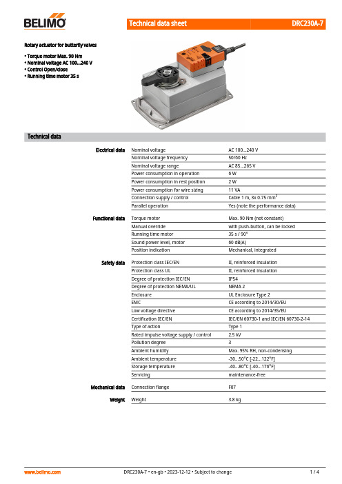
DRC230A-7Rotary actuator for butterfly valves• Torque motor Max. 90 Nm• Nominal voltage AC 100...240 V• Control Open/close• Running time motor 35 sTechnical dataElectrical data Nominal voltage AC 100...240 VNominal voltage frequency50/60 HzNominal voltage range AC 85...265 VPower consumption in operation 6 WPower consumption in rest position 2 WPower consumption for wire sizing11 VAConnection supply / control Cable 1 m, 3x 0.75 mm²Parallel operation Yes (note the performance data)Functional data Torque motor Max. 90 Nm (not constant)Manual override with push-button, can be lockedRunning time motor35 s / 90°Sound power level, motor60 dB(A)Position indication Mechanical, integratedSafety data Protection class IEC/EN II, reinforced insulationProtection class UL II, reinforced insulationDegree of protection IEC/EN IP54Degree of protection NEMA/UL NEMA 2Enclosure UL Enclosure Type 2EMC CE according to 2014/30/EULow voltage directive CE according to 2014/35/EUCertification IEC/EN IEC/EN 60730-1 and IEC/EN 60730-2-14Type of action Type 1Rated impulse voltage supply / control 2.5 kVPollution degree3Ambient humidity Max. 95% RH, non-condensingAmbient temperature-30...50°C [-22...122°F]Storage temperature-40...80°C [-40...176°F]Servicing maintenance-freeMechanical data Connection flange F07Weight Weight 3.8 kgDRC230A-7••••••••••Safety notesThis device has been designed for use in stationary heating, ventilation and air-conditioning systems and must not be used outside the specified field of application, especially in aircraft or in any other airborne means of transport.Outdoor application: only possible in case that no (sea) water, snow, ice, insolation or aggressive gases interfere directly with the device and that it is ensured that the ambient conditions remain within the thresholds according to the data sheet at any time.Caution: Power supply voltage!Only authorised specialists may carry out installation. All applicable legal or institutional installation regulations must be complied with during installation.The switch for changing the direction of rotation may not be adjusted.The angle of rotation is not permitted to be subjected to mechanical limitation. It is forbidden to alter the mechanical end stops.The device may only be opened at the manufacturer's site. It does not contain any parts that can be replaced or repaired by the user.Cables must not be removed from the device.The device contains electrical and electronic components and must not be disposed of as household refuse. All locally valid regulations and requirements must be observed.Because of its non-constant torque, the actuator is neither suitable nor released formotorisation with valves from other manufacturers. No legal entitlement can be claimed, even after extensive testing. Belimo will not be held liable and will provide no warranty.Product featuresSimple direct mountingSimple direct mounting on the butterfly valve. The mounting orientation in relation to the butterfly valve can be selected in 90° (angle) increments.Manual overrideManual override with push-button possible (the gear train is disengaged for as long as the button is pressed or remains locked).High functional reliabilityThe actuator is overload protected, requires no limit switches and automatically stops when the end stop is reached.Torque not constantDue to the non-linear torque characteristic the actuator can only be used for butterfly valvesand not for other armatures.AccessoriesElectrical accessoriesDescriptionType Auxiliary switch 1x SPDT add-on S1A Auxiliary switch 2x SPDT add-onS2A Feedback potentiometer 140 Ω add-on P140A Feedback potentiometer 1 kΩ add-on P1000A Feedback potentiometer 10 kΩ add-onP10000ADRC230A-7Wire colours:1 = blue 2 = brown 3 = whiteElectrical installationCaution: Power supply voltage!Wiring diagramsAC 230 V, open/closeDimensionsFurther documentation• The complete product range for water applications• Data sheets for butterfly valves• Installation instructions for actuators and/or butterfly valves• General notes for project planning。
CM-230系列电导仪说明书

电导率仪使用说明书一、使用前注意事项:1、安装、使用前请详细阅读本说明书相关章节,防止错误操作,造成测量误差或仪表损坏。
2、不恰当的安装和不合适的流速会使测量出现很大偏差,请详细了解安装章节。
3、此仪表属于精密电化学仪表,应由了解和掌握该专业知识的人员负责安装、操作。
二、保修条款:1、自购买之日起,产品质量保证期为一年。
在质量保证期内,产品出现质量问题,公司负责免费维修或更换产品。
2、公司对售出产品提供终身维护服务。
3、对下列原因造成产品的损坏,不在保修范围之内:A、使用、维护不当造成的烧毁、浸水;B、未经许可进行的改装和误用;C、超出本公司产品规定的使用环境造成的损坏;D、因选型不当造成的附带损失;E、安装、使用不当造成的线缆断裂、损坏;F、私自拆线或接线造成传感器测量不准;G、不谨慎拆卸造成的接头内部断线。
目录一、产品概述 ........................... (2)二、型号、基本性能 (2)三、主要技术指标 (3)四、前面板说明 (4)五、操作说明 (4)六、仪表接线 (8)七、测量电极安装 (8)八、常见故障及排除 (9)九、计量检定方法 (9)十、维护保养 (9)十一、仪器成套性 (9)一.概述CM-230(330)X系列智能型在线电导率仪表,为CM230、230双限、330、240、340的升级替代产品。
键盘式设置电极常数,上、下限报警,可迁移4~20mA电流信号输出,通过按键切换查看介质温度、μS/cm和ppm(TDS)转换,自动量程转换,可选配三种电极常数(0.1cm-1、1.0cm-1、10.0cm-1),支持更宽的测量范围。
超稳定测量采集,宽温度、低漂移设计,测量状态可以进行电导率/温度/TDS切换,水质超标报警功能,高亮度背景光LCD显示。
适用于电渗析、反渗透、离子交换制水系统、冷却水控制系统和一般工业用水的在线监测与控制。
二.型号及基本功能:注:回差值为设置的报警值的1.5%三.主要技术指标★测量范围:电导率:0~19.990~199.9μS/cm(0.1cm -1?电极)0~19.990~199.9、0~1999μS/cm(1.0 cm -1?电极) 0~199.9μS/cm0~1999μS/cm0~19.99mS/cm(10cm -1?电极)温度:0-50℃。
UT232钳形数字功率计使用说明书

目录
页
3 4 5 5 5 5 6 6 6 7 7 8 10 11 12 12 13
1
UT232 使用说明书
项目
7-3 有功功率(kW)+相位角(PG)测量 7-4 视在功率(kVA)+无功功率(kVar)测量 7-5 功率因数(PF)+相位角(PG)测量 7-6 电能(kWh)测量 八、电池的更换 九、保养与维护
准确度 分辨率
电压范围
15V
100V 300V 600V
0.60kW 4.00kW 12.00kW 24.00kW
1.50kW 10.00kW 30.00kW 60.00kW
6.00kW 40.00kW 120.0kW 240.0kW
15.00kW 100.0kW 300.0kW 600.0kW
±(3%+5)
的要求。如测试笔破损需要更换,必须换上同样型号 和相同电气规格的测试笔。 不要使仪表暴露在强光、高温或潮湿的地方。
请使用湿布或清洁剂来清洁仪表外壳,请勿使用磨擦 物或溶剂。
仪表潮湿时,请先干燥后存储。 警告 使用仪表之前,请先仔细阅读本操作手册特别是安全 内容!
安全标志 重要安全标志,参考说明书 高压危险 接地 双重绝缘(Ⅱ类安全设备) 电池欠压
3
欧爱吉.中国
UT232 使用说明书
二、特点
UT232三相钳形数字功率表是一款手持式智能功率 测量仪表,它集数字电流表和功率测量仪于一体。仪 表由电压、电流、功率三个通道和微型单片机系统组 成,配有强大的测量和数据处理软件,完成电压、电 流、有功功率、功率因素、相位角、视在功率、无功 功率、电能、频率等参数的测量、计算和显示,性能 稳定,操作简便。尤其适用于现场电力设备以及供电 线路的测量和检修,仪表为手持式钳形结构,体积 小、重量轻,用户可随身携带,使测量变得轻松、快 捷。对于功率测量的用户,UT232是您理想的选择。
TCR-230单边带电台试验器使用说明书

机载电子设备维修测试及故障分析方法编 写: 贺 军中信海直通用航空维修工程有限公司第一章:机载电子设备维修检测基本方法:第一节:检修程序:1、了解情况:1.1、维修人员接收到送检故障件后首先要通过送检故障单,阅读送检设备部件的历史资料等,了解故障现象和分析故障原因,作出初步故障判断。
1.2、按照送检设备件号查询和准备与该部件相符合的维修手册和相关技术资料,准备试验器和检测设备及连接电缆等附件。
1.3、如果送修件不是自己非常熟悉该设备电路原理和已经对该部件很有维修经验的时候,首先要静下心来认真消化该设备部件的维修手册,熟悉该部件整机电路工作原理和认真分析有可能与故障相关的电路。
1.4、按照维修校验规程连接好试验器、检测设备、故障部件。
1.5、按照校验规程检测故障部件,确认送检部件是否与送检故障相符。
2、检查压缩故障点:检查压缩,就是利用静态和动态实施检修的过程。
首先要进行对保险装置的检查,保险装置包括安装在部件上的速熔断保险丝、电源保安反向接入二极管、稳压二极管等进行检查,如有故障首先予以排除,保险装置检查合格后,方可通电检测。
常言道要“通过现象看本质”,检修故障也是如此,要能够顺利的压缩故障点,首先要认真、仔细、全面、准确地观察该部件故障现象,观察看电路板上有没有烧黑损坏的元器件,电路板上有没有异常的地方等,把握了故障现象在理论的指导下,作出正确的分析判断,按照一定的检修原则和方式,便可排除故障点。
3、修复检验:在检查压缩到故障点后,应立即修复,然后要加以检验。
检验的内容包括工艺焊接质量、机械性能和电气技术性能是否合格等。
检验方法应根据具体情况和校验规程条件确定,最简单的故障维修也要经过调整使用、试机,运用测试仪表和试验器进行技术指标检查,以确保主要技术性能指标达到维修手册的要求。
第二节:检修原则:为了正确而有效地实施检修,确保检修质量和安全,迅速修复,必须遵守一定的检修原则。
先思索后动手、先电源配件后机器、先外后内、先静后动、先简(易)后繁(难)、先通病后特殊等,这“六先六后”是每一个机载电子设备维修人员在检修中要遵守的原则。
DCS800-EP 230V Conversion Kit 用户指南说明书
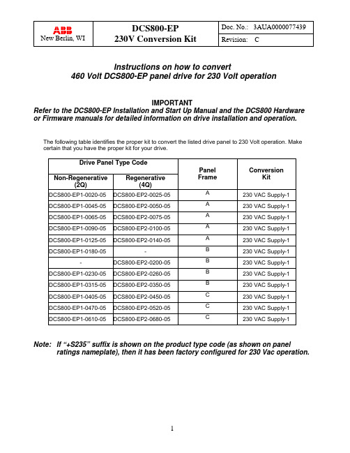
Instructions on how to convert460 Volt DCS800-EP panel drive for 230 Volt operationIMPORTANTRefer to the DCS800-EP Installation and Start Up Manual and the DCS800 Hardware or Firmware manuals for detailed information on drive installation and operation.The following table identifies the proper kit to convert the listed drive panel to 230 Volt operation. Make certain that you have the proper kit for your drive.Drive Panel Type CodePanel Frame ConversionKitNon-Regenerative(2Q) Regenerative(4Q)DCS800-EP1-0020-05DCS800-EP2-0025-05 A 230 VAC Supply-1DCS800-EP1-0045-05DCS800-EP2-0050-05 A 230 VAC Supply-1DCS800-EP1-0065-05DCS800-EP2-0075-05 A 230 VAC Supply-1DCS800-EP1-0090-05DCS800-EP2-0100-05 A 230 VAC Supply-1DCS800-EP1-0125-05DCS800-EP2-0140-05 A 230 VAC Supply-1DCS800-EP1-0180-05- B 230 VAC Supply-1 -DCS800-EP2-0200-05 B 230 VAC Supply-1 DCS800-EP1-0230-05DCS800-EP2-0260-05 B 230 VAC Supply-1DCS800-EP1-0315-05DCS800-EP2-0350-05 B 230 VAC Supply-1DCS800-EP1-0405-05DCS800-EP2-0450-05 C 230 VAC Supply-1DCS800-EP1-0470-05DCS800-EP2-0520-05 C 230 VAC Supply-1DCS800-EP1-0610-05DCS800-EP2-0680-05 C 230 VAC Supply-1 Note: If “+S235” suffix is shown on the product type code (as shown on panel ratings nameplate), then it has been factory configured for 230 Vac operation.INTRODUCTIONReconfiguring a 460 Vac DCS800-EP panel drive for 230 Vac operation can be easily accomplished by using a conversion kit and following the steps below. These steps are intended as a guide and may not cover all required changes for every application. It is the user’s responsibility to consider all conditions before restarting the application.________________________________________________________________________ Important! Only qualified electricians are allowed to install and maintain the drive. Neverwork on the drive, motor cable or motor or attempt reconfiguration when power is applied.________________________________________________________________________ ________________________________________________________________________ Most DCS800-EP panel drives are shipped ready for 460 Vac input power connection.Panel drives that are prewired for 230 Vac are clearly marked with a sticker on the panelratings nameplate or with the suffix “+S235” in the product type code. These instructionsdo not apply to drives already configured for 230 Vac operation.________________________________________________________________________ Panel A - DCS800-EPx-0020-05 thru DCS800-EPx-0140-05The Control Circuit transformer is located under the DCS800 drive module.1.If the DCS800-EP panel drive is already installed, disconnect and lock out all sources of power.2.Remove the cover from the DCS800 module by removing the control panel and pressing down on the twotabs at the lower corners with a screwdriver.Panel A - Continued3.Disconnect the (5) pull-apart control terminal blocksas shown. Then disconnect (1) pull-apart terminalblock at the top of the drive module for the fans. (not shown)4.Remove the (4) drive module mounting screws andcarefully move the module to allow access to thecontrol circuit transformer. Avoid unnecessary stress on any power or control wires.5.Remove insulator plate by unscrewing the (4)mounting screws.Panel A - Continued6. Remove the jumper between H2 and H3, noting that this isactually two jumpers stacked together. Separate the two and jumper H1 to H3 and H2 to H4. Confirm that all connections are tight.See wiring diagram on page 7.7.Secure the insulator plate using the (4) mounting screws. Replace the drive module to its original positionand replace the (4) mounting screws. Confirm that the screws are tight.8.Reconnect the (5) pull apart terminal blocks removed in step 3, and the fan terminal block on top of thedrive module. Then replace the drive module cover, secure, and replace the control panel.The control circuit transformer fuses are located above the drive module and are marked F4, F5 and F6.9. Pull the F4 and F5 fuse holders open and replace the (2)ATQR1-1/8 with the (2) ATQR2 supplied in the kit. Close the holders when finished.IMPORTANT: Be sure to use the correct fuses; the kit maycontain more than one type.10. Affix the “wired for 230Vac” label near the ratingsnameplate located to the left of the drive module.Panel A – Test and Setup________________________________________________________________________Important! Only qualified electricians are allowed to install and maintain the drive. Do not proceed to additional steps until the correct wiring is complete.________________________________________________________________________11. Pull the F6 fuse holder open to disconnect the secondary from the drive logic.12.Apply 230 Volts AC to the drive panel. Using an appropriate VOM, confirm that the control transformersecondary voltage is 110 Volts AC as measured between the top of F6 and panel terminal #2. If the correct voltage is present, close the fuse holder to reconnect the secondary to the drive logic.13. SETUP: Access the drive programming via the Control Panel and change parameter 99.10 (Nominal ACmains voltage) to a value of “230”.14. The drive panel is now ready for operation on 230 Volts ac.Test withF6 fuse pulled open Test PointsPanel B - DCS800-EPx-0180-05 thru DCS800-EPx-0350-05The control circuit transformer is located behind the main ac input fuses (F1,F2,F3) . Access to the jumpers is above the main fuse mounting plate.1.If the DCS800-EP panel drive is already installed, disconnect and lock out all sources of power.2.Remove the jumper between H2 and H3, noting that this is actually two jumpers stacked together.Separate the two and jumper H1 to H3 and H2 to H4. Confirm that all connections are tight.See wiring diagram on page 7.Control transformer fuses are located directly above the main fuses and are marked F4, F5 and F6.Panel B - Continued3. Pull the F4 and F5 fuse holders open andreplace the (2) ATQR1-1/8 with the(2) ATQR2 supplied in the kit. Close the holders when finished.IMPORTANT: Be sure to use the correctfuses; the kit may contain more than one type.4. Affix the “wired for 230Vac” label near theratings nameplate located above the drive module.Factory 460V connection 230V reconnectionPanel B – Test and Setup________________________________________________________________________ Important! Only qualified electricians are allowed to install and maintain the drive. Do notproceed to additional steps until the correct wiring is complete.________________________________________________________________________Test PointsTest with F6fuse holderpulled open5.Pull the F6 fuse holder open to disconnect the secondary from the drive logic.6.Apply 230 Volts AC to the drive panel. Using an appropriate VOM, confirm that the control transformersecondary voltage is 110 Volts AC as measured between the top of F6 and panel terminal #2. If the correct voltage is present, close the fuse holder to reconnect the secondary to the drive logic.7.SETUP: Access the drive programming via the Control Panel and change parameter 99.10 (Nominal ACmains voltage) to a value of “230”.8.The drive panel is now ready for operation on 230 Volts ac.Panel C - DCS800-EPx-0405-05 thru DCS800-EPx-0680-05On the C frame drives built before May, 2013, the control transformer is located to the right of the drive module and is accessible without removing any other equipment.On C frames built since May, 2013, the control transfomer is in the approximate same location but below the bracket (on the same level as the fuses).1.If the DCS800-EP panel drive is already installed, disconnect and lock out all sources of power.2.Remove the jumper between H2 and H3, noting that this is actually two jumpers stacked together.Separate the two and jumper H1 to H3 and H2 to H4. Confirm that all connections are tight.See wiring diagram on page 7.Control transformer fuses are located directly above the drive module and are marked F4, F5 and F6.3.Pull the F4 and F5 fuse holders open and replace the (2) ATQR2 fuses with the (2) ATQR3 supplied inthe kit. Close the holders when finished.IMPORTANT: Be sure to use the correct fuses; the kit may contain more than one type.4.Affix the “wired for 230Vac” label near the ratings nameplate located to thelower edge of the drive module.Panel C – Test and Setup________________________________________________________________________Important! Only qualified electricians are allowed to install and maintain the drive. Do not proceed to additional steps until the correct wiring is complete.5. Pull the F6 fuse holder open to disconnect the secondary from the drive logic.6.Apply 230 Volts AC to the drive panel. Using an appropriate VOM, confirm that the control transformersecondary voltage is 110 Volts AC as measured between the top ofF6 and panel terminal #2. If the correct voltage is present, close the fuse holder to reconnect the secondary to the drive logic.7. SETUP: Access the drive programming via the Control Panel and change parameter 99.10 (Nominal ACmains voltage) to a value of “230”.8. The drive panel is now ready for operation on 230 Volts ac.。
UT30B C D F电压计量器操作手册说明书
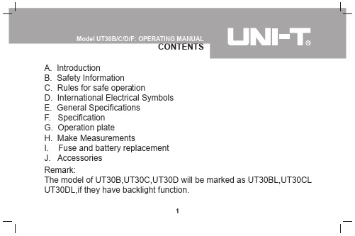
A. IntroductionB. Safety InformationC. Rules for safe operationD. International Electrical SymbolsE. General SpecificationsF. SpecificationG. Operation plateH. Make MeasurementsI. Fuse and battery replacementJ. AccessoriesRemark:The model of UT30B,UT30C,UT30D will be marked as UT30BL,UT30CL UT30DL,if they have backlight function.1UT30 series Multimeter is 3 1/2 digits with steady operations,fashionable structure and highly reliable hand-held measuring instrument. The meter can measure DC/AC voltage, DC/AC current, Resistance, Frequency, Temperature, Diode, Transistor hFE, and Continuity. It is an ideal tool for maintenance.2This Meter complies with the standards IEC61010: in pollution degree 2, overvoltage category (CAT I 600V, CAT II 300V) and double insulation.CAT. I: Signal level, special equipment or parts of equipment, telecommunication, electronic, etc., with smaller transient overvoltages than overvoltages CAT. II.CAT. II: Local level, appliance, PORTABLE EQUIPMENT etc., with smaller transient overvoltages than CAT. IIIUse the Meter only as specified in this operating manual, otherwise the protection provided by the Meter may be impaired.3l Use the meter only as the rules specified in this manual, otherwise,the protection provided by the meter may be impaired.l Do not operate the meter unless the bottom case has been closed as terminal can carry voltage.l Inspect the insulation of the test leads and make sure there is nodamage to the test leads before using the meter.l As soon as the battery indicator’s“ ” appear, replace the battery toensure accurate readings.l Set the meter to suitable function and range before each measurement. l Tested values over the maximum range of each measurement cancause damages to the meter or electric shock to users.l To avoid damages of the meter, do not turn the rotary switch duringmeasurement4l When measuring voltage higher than DC 60V or AC 30Vrms, pay extra attention to avoid electric shock.l Make sure to replace right type and right rating fuse.l Do not operate or store the Meter under high temperature or humid condition.l Do not change internal circuit to avoid damages to the meter anddanger to the user.l Periodically wipe the case with damp cloth and mild detergent. Do not use abrasives and solvents.l The meter is designed to withstand the stated maximum voltages. If it not possible to exclude without doubts that impulses,transients, disturbance or for other reasons these voltages are exceeded,a suitable prescaler (1:10) must be used.5Conforms to Standards of European Union.61. The maximum voltage, between any terminal and earth, is 600Vrms.A . The“COM”input terminal is always connected with the black testlead.B . The“VΩmA”input terminal is always connected with the red testlead and is used to measure voltage up to 500V,resistance andcurrent up to 200mA.C . The“10A MAX”input terminal is always connected with the red test lead and is used to measure current greater than 200mA but nomore than 10A.2. 10A Terminal: non-fused3. mA Terminal Fuse: ø5x20-315mA, 250V.(Fast)4. Maximum Display is 1999,and updates two or three times every second.5. Over range display is “1” or “OL”. (Only UT30F).76. Temperature:Operating: 0C-40C (32 F-104 F)Storing:-10C-50C (14 F -122 F)7. Altitude:Operating:2000mStorage:10000m8 Relative humidity:Max.relative humidity 80% for temperature up to 31C decreasing linearly to 50% relative humidity at 40C.9. Battery: 9V NEDA 1604 or 6F22 or 006P.10. Low Battery Indication: Display “ ”.on LCD.11. Dimension:75mmx130mmx36mm12. Weight: approx. 150g(Test Leads not included)8Accuracy: (a% reading + b digit), which guarantee one year.C CRelative Humidity: <75%1. DC VoltageInput Impedance:10MΩ for all the ranges.Overload protection: At 200mV range, it’s protected at 230V(AC / DC Current), others are protected at 500V(AC or DC).9Input Impedance: (approx. 5MΩ ) of UT30B\C\D, but all ranges of UT30F are 10MΩ .Frequency: 40-400HzDisplay: RMS of Sine Wave Value (Average Value)Overload protection: At 200mV range, it is protected at 230V(AC / DC Current), others are protected at 500V(AC or DC )103. DC CurrentOverload Protection:315mA/250V fuse, No fuse at 10A,measuring time limit is equal to or less than 10 seconds, and time interval should be equal to or over 15 minutes.Measuring voltage drop: Full range is 200m V.114. AC Current(Only UT30F)Overload Protection: 315mA/250V fuse, No fuse at 10A,measuring time limit is equal to or less than 10 seconds; time interval is equal to or over 15 minutes.Frequency response: 40Hz-400HzDisplay: RMS of Sine Wave Value (Average Value)125. ResistanceOverload Protection: All ranges are 230V(DC/ AC current).13147. Frequency(Only UT30F Auto Range)8. Square Wave Output(Only UT30D)15No overload protection for this range; make sure voltageoutput of calibrated equipment is less than 10V to avoid damages to the Meter.9. Diode, Transistor, Continuity Beeper Test1617Overload Protection: 230V(DC/ AC current),OnlyOperation Plate(see figure 1)1. Liquid Crystal Display2. Data hold or backlight selection buttonexcept UT30F(AC/ DC exchange)*3. Rotary Switch4. Transistor Test Jack5. Common Input Jack6. 10A Input Jack7. Input Jack for General Measurement* If the model has backlight function as UT30BL,UT30CL,UT30DL, press the button abidingly over 3 seconds,backlight will be opened, it will shut off automatically after 20 seconds late.First, set rotary switch to proper position. When the battery is low,“ ”will appear on LCD. Second, the “” symbol beside the input jack warns you when testing current and voltage. Input values must not exceed the limit.1.DC Voltage Measurement(see figure 2)181) Never measure voltage value exceeding 500V, although it is possible to get the reading. This may cause damages to the internal circuit and danger to users;2) Set rotary switch to maximum range, if the voltage value to be tested is unknown. Then according to reading requirement adjust to a lower range until satisfactory reading is obtained.3) If “1”or “OL” is shown on LCD, set to the higher range because theselected range is overloaded.4) At every range, input impedance is 10MΩ This can cause measuring tolerance at high impedance, If circuit impedance is equal to or less than 10kΩ ,you can ignore the tolerance(0.1% or lower).192. AC Voltage Measurement (see figure 3)Same as DC voltage measurement.203. DC Current Measurement(see figure 4)1) Do not measure when value between open voltage and earth isexceeding safety voltage 60V because it may cause damages to the measuring object or instrument and also hurt the user.212) Before measurement, cut off the power to the object to be measured and inspect if input terminal or rotary switch is set to the right range then you can measure the object with power on.3) If the magnitude of current is unknown, set rotary switch to the highest range and then adjust to a lower range until a satisfactory reading is obtained.4) If the meter is overloaded on mA input jack the fuse will melt up. In this case, replace with a new fuse with same specification.5) The dimension of fuse is ø5x20(mm)and the specification is F.315mA/ 250V (FAST).6) For 10A input jack, it is non-fused. For safety, each measuring timeshould be equal to or less than 10 seconds. Time intervals should be equal to or over 15 minutes.224. AC Current Measurement(Only for UT30F)(see figure 5)Same as DC current measurement23245. Resistance Measurement (see figure 6)(figure 6)1) To avoid damages to the Meter whenmeasuring resistance, cut off the powerof the object and make sure there is nocharge in capacitor.2) Test lead wires take 0.1Ω -0.3Ω tolerancewhen measuring resistance. To get anaccurate reading, subtract the short circuit values of the 2 test leads.3) It will take several seconds for the display to become stabilized when resistance valueis over 1M Ω.256. Diode measurement (see figure 7)(figure 7)1) Avoid damages to the meter. Whenmeasuring diode, cut off the power supplyof the object and make sure there is nocharge in capacitor.2) When measuring voltage drop of diode,transistor, and other semiconductorcomponent at diode function, its silicon semiconductor structure should be normalpositive reading and stay between 0.5Vand 0.8V. Negative display being “1” means open circuit; when the red test lead ispositive pole and the black one is negative pole.7. Transistor hFE Measurement (see figure 8)1) Check that the transistor is2) Connect the transistor to bemeasured to the correspondingjacks.3) LCD display hFE reference value.4) Measuring condition:Ibo 10µA,Vce 3V(figure 8)268. Temperature Measurement:(Only for UT30C)(see figure 9) 1) Insert the black K type thermocouple(P/N:41700103) into “COM” socket.LCD displays the measuring value withunit in C.2) The temperature probe limits to below250C. For a higher degree of temperaturemeasurement, use another hand-heldthermocouple (P/N:41700107). The LCDdisplay room temperature when unloadingthe probe.(figure9)279. Square Wave Output:(Only UT30D) (see figure 10) 1) To avoid damages to the meter, dohigher then 10V voltage.2) The frequency is 50Hz.3) The output voltage range will beover 3V when it is loaded 1MΩ.4) Use square wave output to repairaudio equipment.(figure10)2810. Frequency Measurement (Only for UT30F)(see figure 11)1) Do not input voltage over 230V RMS toavoid damages to the meter.2) The LCD will display reading when themeasured frequency is more than 10V,but the read out may exceed specification.To obtain an accurate, stable reading, anexternal attenuator should be used.3) To measure high frequency signal in highblack red interferenced environment use shieldedcable.(figure11)29301) Turn the rotary switch to OFF position,and remove the test leads from terminals.2) Remove two rubber feet and two screws from the bottom case.3) Separate the bottom case from the top case.4)H. Fuse and battery replacement (see figure 12)(figure12)Replace the battery or fuse as per the following specification:Battery: 9V NEDA 1604 or 6F22 or 006P Fuse:a) mA Terminal: ø5x20-315mA, 250V (Fast)b) 10A Terminal: Unfused 5) Rejoin the bottom case and top case,and reinstall two screws and two rubber feet.** END **This operating manual is subject to change without notice.1) Operating manual2) Test leads3) Thermocouple(Only for UT30C)31Copyright 2001 Uni-Trend International Limited. Manufacturer:Uni-Trend International LimitedRm901, 9/F, Nanyang Plaza57 Hung To RoadKwun TongKowloon, Hong KongTel: (852) 2950 9168Fax: (852) 2950 9303Email:******************32。
数字钳式万用表使用说明书

创作编号:BG7531400019813488897SX创作者:别如克*数字钳式万用表一、概述UT250、UT206是一种性能稳定,安全可靠的33/4位数数字钳形表(一下简称仪表)系列。
整机电路设计以大规模集成电路双积分A/D转换器为核心,全量程的过载保护电路,独特的外观设计使之成为性能优越的专用电工仪表。
仪表可用于测量交直流电压、交流电流、电阻、二极管、电路通断、电容、频率/占空比或温度。
二、测量操作说明1、交流电流测量(1)将功能量程快关置于1000A~交流电流测量档。
(2)按下板机,张开钳头把导线夹住两根或以上的不同电流流向导线的测量将得不到正确的测来那个结果。
(3)从显示器上读取测量结果,为正弦波有效值(平均值响应)。
2、直流电压测量(1)将红表笔插入“V”插孔,黑表笔插入“COM”插孔。
(2)将功能量程开关置于直流电压测量档,并将表笔并联到待测电源或负载上。
(3)从显示器上读取测量结果。
3、交流电压测量(1)将红表笔插入“V”插孔,黑表笔插入“COM”插孔。
(2)将功能量程开关置于交流电压测量档,并将表笔并联到待测电源或负载上。
(3)从显示器上读取测量结果,为正弦波有效值(平均值响应)。
4、电阻测量(1)将红表笔插入“HZΩ”插孔,黑表笔插入“COM”插孔。
(2)将功能量程开关置于“Ω”档(电阻测量功能为默认值),并将表笔并联到被测电阻上。
(3)从显示器上读取测量结果。
5、二极管测试(1)将红表笔插入“HZΩ”插孔,黑表笔插入“COM”插孔。
红表笔极性为“+”。
黑表笔极性为“—”。
(2)将功能量程开关置于“”测量档,再按SEECTL键选择进入二极管测试功能,红表笔接到被测二极管的正极,黑表笔接到二极管的负极。
(3)从显示器上读取被测二极管的近似正向压降值,一般为0.5~0.8V。
6、电路通断测试(1)将红表笔插入“HZΩ”插孔,黑表笔插入“COM”插孔。
(2)将功能量程开关置于“·)))”档,再按SEECTL键选择进入电路通断测试功能,并将表笔并联到被测电路两端。
Belimo NM230A-C173 调节器说明书
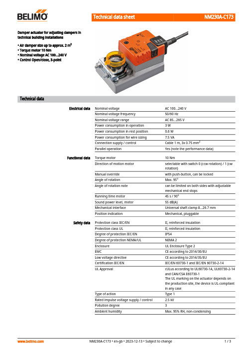
NM230A-C173Damper actuator for adjusting dampers intechnical building installations• Air damper size up to approx. 2 m²• Torque motor 10 Nm• Nominal voltage AC 100...240 V• Control Open/close, 3-pointTechnical dataElectrical data Nominal voltage AC 100...240 VNominal voltage frequency50/60 HzNominal voltage range AC 85...265 VPower consumption in operation 3 WPower consumption in rest position0.6 WPower consumption for wire sizing7.5 VAConnection supply / control Cable 1 m, 3x 0.75 mm²Parallel operation Yes (note the performance data)Functional data Torque motor10 NmDirection of motion motor selectable with switch 0 (ccw rotation) / 1 (cwrotation)Manual override with push-button, can be lockedAngle of rotation Max. 95°Angle of rotation note can be limited on both sides with adjustablemechanical end stopsRunning time motor45 s / 90°Sound power level, motor55 dB(A)Mechanical interface Universal shaft clamp 8...26.7 mmPosition indication Mechanical, pluggableSafety data Protection class IEC/EN II, reinforced insulationProtection class UL II, reinforced insulationDegree of protection IEC/EN IP54Degree of protection NEMA/UL NEMA 2Enclosure UL Enclosure Type 2EMC CE according to 2014/30/EULow voltage directive CE according to 2014/35/EUCertification IEC/EN IEC/EN 60730-1 and IEC/EN 60730-2-14UL Approval cULus according to UL60730-1A, UL60730-2-14and CAN/CSA E60730-1The UL marking on the actuator depends onthe production site, the device is UL-compliantin any caseType of action Type 1Rated impulse voltage supply / control 2.5 kVPollution degree3Ambient humidity Max. 95% RH, non-condensingSafety dataAmbient temperature -30...50°C [-22...122°F]Storage temperature -40...80°C [-40...176°F]Servicingmaintenance-free WeightWeight 0.72 kg••••••••Safety notesThis device has been designed for use in stationary heating, ventilation and air-conditioning systems and must not be used outside the specified field of application, especially in aircraft or in any other airborne means of transport.Outdoor application: only possible in case that no (sea) water, snow, ice, insolation or aggressive gases interfere directly with the device and that it is ensured that the ambient conditions remain within the thresholds according to the data sheet at any time.Caution: Power supply voltage!Only authorised specialists may carry out installation. All applicable legal or institutional installation regulations must be complied with during installation.The device may only be opened at the manufacturer's site. It does not contain any parts that can be replaced or repaired by the user.Cables must not be removed from the device.To calculate the torque required, the specifications supplied by the damper manufacturers concerning the cross-section and the design, as well as the installation situation and the ventilation conditions must be observed.The device contains electrical and electronic components and must not be disposed of as household refuse. All locally valid regulations and requirements must be observed.Product featuresSimple direct mountingSimple direct mounting on the damper shaft with a universal shaft clamp, supplied with an anti-rotation device to prevent the actuator from rotating.Manual overrideManual override with push-button possible (the gear train is disengaged for as long as the button is pressed or remains locked).Adjustable angle of rotation Adjustable angle of rotation with mechanical end stops.High functional reliabilityThe actuator is overload protected, requires no limit switches and automatically stops when the end stop is reached.AccessoriesElectrical accessoriesDescriptionType Auxiliary switch 1x SPDT add-on S1A Auxiliary switch 2x SPDT add-onS2A Feedback potentiometer 140 Ω add-on P140A Feedback potentiometer 1 kΩ add-on P1000A Feedback potentiometer 10 kΩ add-onP10000A Mechanical accessoriesDescriptionType Actuator arm for standard shaft clamp (one-sided)AH-25Shaft extension 240 mm ø20 mm for damper shaft ø8...22.7 mm AV8-25Ball joint suitable for damper crank arm KH8KG8Ball joint suitable for damper crank arm KH8 / KH10KG10A Damper crank arm Slot width 8.2 mm, clamping range ø10...18 mm KH8Shaft clamp one-sided, clamping range ø8...26 mm with insert, Multipack 20 pcs.K-ENMA Shaft clamp one-sided, clamping range ø8...26 mm, Multipack 20 pcs.K-ENSA Shaft clamp reversible, clamping range ø8...20 mmK-NADescriptionType Form fit insert 8x8 mm, Multipack 20 pcs.ZF8-NMA Form fit insert 10x10 mm, Multipack 20 pcs.ZF10-NSA Form fit insert 12x12 mm, Multipack 20 pcs.ZF12-NSA Form fit insert 15x15 mm, Multipack 20 pcs.ZF15-NSA Form fit insert 16x16 mm, Multipack 20 pcs.ZF16-NSA Mounting kit for linkage operation for flat installation ZG-NMA Anti-rotation mechanism 180 mm, Multipack 20 pcs.Z-ARS180Baseplate extension for NM..A to NM..Z-NMA Position indicator, Multipack 20 pcs.Z-PIWire colours:1 = blue 2 = brown 3 = whiteElectrical installationCaution: Power supply voltage!Parallel connection of other actuators possible. Observe the performance data.Wiring diagrams AC 230 V, open/closeAC 230 V, 3-pointDimensionsSpindle lengthMin. 40Min. 20Clamping range*Option: Shaft clamp mounted below(accessories K-NA needed)。