spice仿真
第7章 SPICE语言及电路仿真
第7章 SPICE语言及电路仿真模块概要:一、学习目标1、了解SPICE的电路设计流程及HSPICE电路仿真工具。
2、掌握SPICE编程语言与编程技术。
3、能够使用HSPICE软件进行电路仿真。
二、学习指南能够读懂电路输入网表,理解地掌握SPICE语言中分析及控制语句的设置,在仿真实例中学会编程技术和仿真方法。
三、知识内容SPICE语言介绍:SPICE含义、产生、著名软件、SPICE的电路设计流程。
输入语句的结构与规定输入语句的结构、规定、一个简单实例。
电路元器件描述语句无源器件描述语句、有源器件描述语句、电源描述语句、其它语句。
电路特性分析语句直流分析、交流分析、瞬态分析、蒙特卡罗分析和灵敏度/最坏情况分析、温度分析。
电路特性控制语句初始状态设置语句、参数、函数定义语句、重置参数语句、输出控制语句。
缓冲驱动器设计实例以缓冲驱动器的设计实例,来说明电路网表的编写、直流分析、时序分析、驱动能力的设计过程。
放大器设计实例以一个常用的运算放大器设计实例,详细地说明各种指标的实现、各种仿真分析的进行过程。
设计方法与设计工具介绍—电路仿真介绍集成电路著名而常用的模拟电路仿真软件HSpice,包括HSpice简介、HSpice的特点与结构、HSpice的具体功能、HSpice的流程、HSpice的输入——网单文件、HSpice的输出等。
四、练习1.国际公认的_______________________________工具是美国加利福尼亚大学伯克利分校开发的____________程序。
答案:模拟电路通用仿真、SPICE2. 商用的SPICE软件主要有________、________、________、________与________等。
答案:Hspice、Pspice、SBTspice、SmartSPICE、Tspice3. HSPICE是____________公司开发的一个商业化通用电路模拟程序,它可以从_______到高于_______的微波频率范围内,对电路作精确的仿真、分析和优化。
ltspice移相全桥仿真
ltspice移相全桥仿真
首先,请确保您已经安装了LTspice软件,并且熟悉基本的操作方法。
接下来,根据您的需求,设计出您想要仿真的移相全桥电路。
这包括选择合适的三极管、电感、电容等元件,并且连接它们以满足移相全桥的功能需求。
然后,在LTspice中打开一个新的电路图窗口,开始绘制您的电路图。
使用适当的元件、连线和标记来表示您的移相全桥电路。
接下来,为每个元件选择合适的型号和参数。
您可以从元件库中选择现有元件,或者自定义您自己的元件。
然后,将适当的电源和信号源连接到您的电路中,以提供所需的电源电压和输入信号。
接下来,设置仿真的运行时间和仿真参数。
您可以选择在一定时间范围内运行仿真,或者指定特定事件的仿真。
最后,运行仿真并分析结果。
在仿真运行后,您可以查看电路的波形图,以了解电压、电流、功率等参数的变化和响应。
需要提醒的是,由于我无法得知您具体移相全桥电路的设计,以上步骤只是一般的指导,您需要根据您的具体电路设计进行相应的调整和操作。
spice仿真
spice仿真Spice仿真引言Spice (Simulation Program with Integrated Circuit Emphasis) 是一种电路仿真程序,它可以模拟各种电路的性能和行为。
历经多年的发展,Spice已经成为电子设计领域中最为常用和广泛认可的仿真工具之一。
本文将介绍Spice仿真的基本原理、应用领域以及使用方法,帮助读者更好地了解和应用这一强大的工具。
一、Spice仿真的基本原理Spice仿真基于电路的数学模型和电路分析方法,通过求解一组线性或非线性的代数和微分方程来模拟电路的行为。
Spice可以对各种类型的电路进行仿真,包括模拟电路、数字电路以及混合信号电路。
它考虑了电路中各个元件的电性能,并基于电流和电压的关系对电路进行建模和分析。
Spice程序需要用户提供电路的拓扑结构以及各个元件的参数。
通过这些输入,Spice可以根据预定义的电路分析方法和解算器来计算电路中各个节点和元件上的电压、电流以及功率等参数。
通过对电路的相应参数进行实时仿真和分析,Spice可以为设计者提供准确的电路行为信息,帮助他们对电路性能进行优化和改进。
二、Spice仿真的应用领域Spice仿真在电子设计和电路分析中有广泛的应用。
以下列举了几个常见的应用领域:1.模拟电路设计:Spice可以用于模拟电路的设计和验证,帮助设计者检查电路的性能和稳定性。
通过Spice仿真,设计者可以预测电路的频率响应、幅频特性以及相位延迟等参数,从而改进电路的设计方案。
2. 数字电路分析:Spice可以模拟数字电路中的逻辑门、触发器和时序电路等元件,帮助设计者验证电路的正确性和稳定性。
通过仿真结果,设计者可以找出可能存在的逻辑错误和电路延迟,并及时进行优化和调整。
3.射频电路分析:Spice也可以用于射频电路的仿真和分析。
射频电路中经常涉及到高频信号的传输和耦合问题,通过对射频电路进行Spice仿真,设计者可以预测电路中的信号衰减、失真以及噪声等问题,从而优化电路的性能。
电子线路模拟仿真:SPICE软件的基本使用方法
电子线路模拟仿真:SPICE软件的基本使用方法电子线路模拟仿真是现代电子工程中重要的工具之一,它通过计算机软件模拟电子线路的工作原理和性能,能够快速、准确地评估电路设计的有效性。
其中,SPICE软件是目前应用较广泛的一种电子线路仿真软件。
本文将介绍SPICE软件的基本使用方法,包括安装、建立电路模型、设定仿真参数和分析仿真结果等步骤。
一、安装SPICE软件1. 在SPICE软件的官方网站上下载最新版本的软件安装包;2. 双击安装包,按照软件安装向导的提示,选择安装路径并完成安装;3. 打开SPICE软件,确认软件已成功安装。
二、建立电路模型1. 新建电路文件:在SPICE软件的界面上选择“文件-新建”,创建一个新的电路文件;2. 添加元件:通过选择“元件”或“库”菜单,从库中选取所需的元件,并将其拖放到电路模型的工作区中;3. 连接元件:通过选择“连接”工具,在元件之间建立正确的连接关系;4. 设置元件参数:双击元件,弹出元件参数设置对话框,根据需要填写或修改参数值;5. 建立电源:选择适当的电源元件,连接到电路中的合适位置,并设定电源的电压或电流值。
三、设定仿真参数1. 选择仿真类型:在SPICE软件的界面上选择“仿真-仿真设置”,弹出仿真设置对话框;2. 设定仿真时间:根据仿真需求,设置仿真的起始时间和结束时间;3. 设定仿真步长:设置仿真的时间步长,即每个仿真数据点之间的时间间隔;4. 设定仿真类型:选择所需的仿真类型,如直流仿真、交流仿真或脉冲仿真;5. 设定其他仿真参数:根据仿真需求,可以设置其他相关的仿真参数,如温度、频率等。
四、分析仿真结果1. 运行仿真:选择“仿真-运行仿真”或点击运行仿真的工具按钮,开始进行电路仿真;2. 查看仿真结果:仿真结束后,选择“仿真-波形查看器”或点击波形查看器的工具按钮;3. 设置波形显示:在波形查看器中,选择所需显示的电压或电流波形,并设定波形的颜色和线型;4. 分析波形:对波形进行分析,如测量电压峰值、波形周期、频率等。
Spice仿真介绍和操作

数字逻辑基础LOGOEDA工具在数字逻辑课程中的应用--Multisim工具之Spice仿真在模拟电子课程中,我们通过使用晶体管的小信号模型,手工计算得到小规模模拟电子电路电压增益、电流增益、输入阻抗、输出阻抗、频率响应特性等。
⏹这种通过人工计算的分析方法就显得效率很低。
⏹随着计算机性能的不断提高,电子设计自动化(ElectronicDesign Automation,EDA)工具出现。
它成为电子系统设计和分析的强有力的助手。
⏹EDA工具取代了传统的手工计算方法,显著的提高了设计电路和分析电路的效率。
EDA工具在数字逻辑课程中的应用--Multisim工具之Spice仿真以集成电路为重点的仿真程序(Simulation Programwith Integrated Circuit Emphasis,SPICE),它是为了执行日益庞大而复杂的集成电路仿真工业而发展起来的,它是一个通用的、开源的模拟电子电路仿真工具。
⏹SPICE是一个程序用于集成电路和板级设计,用于检查电路设计的完整性,并且预测电路的行为。
⏹SPICE最早由加州大学伯克利分校开发,1975年改进成为SPICE2的标准,它使用FORTRAN语言开发。
在1989年,Thomas Quarles 开发出SPICE3,它使用C语言编写,并且增加了窗口系统绘图功能。
EDA 工具在数字逻辑课程中的应用--Multisim 工具之Spice 仿真在目前流行的NI 公司的Mutisim Workbench 工具、Altium 公司的Altium Designer 工具和Cadence 公司的OrCAD 工具中都嵌入了SPICE 仿真工具。
⏹在SPICE仿真工具中,包含下面的模块:☐电路原理图输入程序。
☐激励源编辑程序。
☐电路仿真程序。
☐输出结果绘图程序。
☐模型参数提取程序。
☐元器件模型参数库。
下面将通过Multisim 环境下的设计实例,演示EDA工具在数字逻辑课程中的应用--Multisim工具之Spice仿真SPICE的基本分析功能包含三大类:⏹直流分析⏹交流分析⏹时域分析EDA工具在数字逻辑课程中的应用--Multisim工具之Spice仿真注1:直流分析是所有其它分析的基础。
SPICE仿真基础

1概览2SPICE仿真概览3SPICE仿真回顾4SPICE仿真模型5基础SPICE仿真模型参数6高级SPICE仿真模型参数7SPICE仿真选项8SPICE仿真控制语句9SPICE仿真源类型与参数10Connexions网站上的SPICE仿真课程11SPICE仿真用户指南概览NI公司的SPICE仿真基础系列是您了解电路仿真的免费互联网资源。
该系列是一组关于SPICE仿真、OrCAD pSPICE仿真、SPICE建模以及电路仿真中其他概念的指南和信息。
该系列分解成多篇深入详细的文档,提供了关于SPICE仿真的重要概念和细节的“如何”信息。
电路仿真对于任何一种设计过程都是一个重要的组成部分。
通过仿真您的电路,您可以在过程的早期发现错误,并避免代价昂贵的、极为耗时的重新进行原型构造的工作。
您也可以方便地更换部件以评估不同材料(BOM)的设计方案。
NI Multisim是一个易于使用的、功能强大的、灵活的SPICE仿真环境的范例,它支持教师们教授电路理论,并允许工程师们快速进行拓扑结构设计。
SPICE仿真概览目录1Overview2SPICE Simulation Program with Integrated Circuit Emphasis (SPICE)3SPICE Simulation Models and Netlists4 A Tradeoff Between Speed and Accuracy5Using SPICE Simulation6Learning MoreOverviewThe National Instruments SPICE Simulation Fundamentals series is your free resource on the internet for learning about circuit simulation. The series is a set of tutorials and information on SPICE simulation, OrCAD pSPICE compatibility, SPICE modeling, and other concepts in circuit simulation.For more information, see the SPICE Simulation Fundamentals main page.The series is divided among a number of in-depth detailed articles that will give you HOW TO information on the important concepts and details of SPICE simulation.Circuit simulation is an important part of any design process. By simulating your circuits, you can detect errors early in the process, and avoid costly and time consuming prototype reworking. You can also easily swap components to evaluate designs with varying bills of materials (BOMs).SPICE Simulation Program with Integrated Circuit Emphasis (SPICE)SPICE is a computer simulation and modeling program used by engineers to mathematically predict the behavior of electronics circuits. Developed at the University of California at Berkeley, SPICE can be used to simulate circuits of almost all complexities. However, SPICE is generally used to predict the behavior of low to mid frequency (DC to around 100MHz) circuits.SPICE Simulation Models and NetlistsSPICE has the ability to simulate components ranging from the most basic passive elements such as resistors and capacitors to sophisticated semiconductor devices such as MESFETs and MOSFETs. Using these intrinsic components as the basic building blocks for larger models, designers and chip manufacturers have been able to define a truly vast and diverse number of SPICE models. Most commercially available simulators include more than 15,000 different components.The quality of SPICE models can vary, and not all SPICE models are applicable to every application. It is important to consider this when using the models supplied with a SPICE simulation package. Using a SPICE model inappropriately can lead to inaccurate results, or even generate an error in some circumstances. One of the most common errors made by even seasoned engineers is confusing a SPICE model with a PSPICE model. PSPICE is a commercially available program that uses proprietary languages to define components and models.A circuit must be presented to SPICE in the form of a netlist. The netlist is a text description of all circuit elements such as transistors and capacitors, and their corresponding connections. Modern schematic capture and simulation tools such as Multisim allow users to draw circuit schematics in a user-friendly environment, and automatically translate the circuit diagrams into netlists. Consider as an example the simple voltage divider circuit below. We include both netlist and corresponding circuit schematic.Voltage Divider Netlist* Any text after the asterisk '*' is ignored by SPICE* V oltage DividervV1 1 0 12rR1 1 2 1000rR2 2 0 2000.OP * perform a DC operating point analysis.ENDVoltage Divider SchematicA Tradeoff Between Speed and AccuracyAlthough the SPICE models used in a SPICE simulation can greatly affect the accuracy of the results, simulation settings also contribute to varying degrees of accuracy. SPICE simulation options generally allow the user to gain more accuracy in the results at the cost of the speed of the simulation.To understand the tradeoff between speed and accuracy in SPICE simulation one must consider a number of factors. SPICE simulation was created over 30 years go and around that time a typical computer had less power than the average microwave oven did thirty years later. Computing power was very expensive. The simulation of a circuit to the highest degree of accuracy could have taken longer and cost more money than building the actual circuit to see the results. Also, consider that the broad purpose of circuit simulation is to augment basic hand calculations and predict general circuit behavior. With these considerations in mind, the designers of SPICE created a program that could produce reasonably accurate results in a cost-effective manner. They also included many options to allow engineers to customize the accuracy of a simulation.As computing power has increased exponentially over the years, so have the complexity of circuit designs being simulated. Speed and accuracy are still important factors to consider when simulating circuits.Using SPICE SimulationSPICE Simulation by itself can be used as a command line or text-based simulation tool. However, to effectively manage large and complex designs that span from simulation through to PCB layoutand routing, several commercial software tools have been built around SPICE and XSPICE including Multisim. Included in Multisim is a graphical user interface to allow quick and efficient schematic capture, and interactive simulation.'Learning MoreTo learn more about SPICE simulation, please see the SPICE Simulation Fundamentals home page.SPICE仿真回顾目录1Overview2SPICE Simulation History3ReferencesOverviewThe National Instruments SPICE Simulation Fundamentals series is your free resource on the internet for learning about circuit simulation. The series is a set of tutorials and information on SPICE simulation, OrCAD pSPICE compatibility, SPICE modeling, and other concepts in circuit simulation.For more information, see the SPICE Simulation Fundamentals main page.The series is divided among a number of in-depth detailed articles that will give you HOWTO information on the important concepts and details of SPICE simulation.Circuit simulation is an important part of any design process. By simulating your circuits, you can detect errors early in the process, and avoid costly and time consuming prototype reworking. You can also easily swap components to evaluate designs with varying bills of materials (BOMs). SPICE simulation has been used for over thirty years to accurately predict the behavior of electronic circuits. Over the years the many revisions of SPICE have seen improvements in both accuracy and speed. In addition to these improvements, additions to the language have allowed simulation and modeling of more complex integrated circuits including MOSFETs.SPICE Simulation HistoryS imulation P rogram with I ntegrated C ircuit E mphasis, or SPICE, has been used for over thirty years. The original implementation of SPICE was developed at the University of California Berkeley campus in the late 1960s. SPICE was developed largely as a derivative of CANCER (Computer Analysis of Nonlinear Circuits, Excluding Radiation) also developed by UC Berkeley. The first widely used version of SPICE was announced in Waterloo, Canada in 1973. Shortly thereafter SPICE was adopted by nearly all major engineering institutions throughout North America. SPICE has evolved into the academic and industry standard for analog and mixed-modecircuit simulation.Over the years additional simulation algorithms, component models, bug fixes, and capabilities were added to the program. Even today SPICE is still the most widely used circuit simulator in the world and as of 2006 the latest version is SPICE 3F5.XSPICE was developed at Georgia Tech as an extension to the SPICE language. XSPICE allows behavioral modeling of components which can drastically improve the speeds of mixed-mode and digital simulations. Multisim from National Instruments is based on SPICE 3F5 and XSPICE and provides additional convergence and speed improvements to complement these powerful simulation languages.ReferencesThe SPICE Book, Andrei Vladimirescu, © 1994 John Wiley & SonsThe Life of SPICE, Laurence W. Nagel, © 1996SPICE仿真模型目录1Overview2What is a SPICE Simulation Model?3Model Makers4Where to look for SPICE Simulation modelsOverviewThe National Instruments SPICE Simulation Fundamentals series is your free resource on the internet for learning about circuit simulation. The series is a set of tutorials and information on SPICE simulation, OrCAD pSPICE compatibility, SPICE modeling, and other concepts in circuit simulation.For more information, see the SPICE Simulation Fundamentals main page.The series is divided among a number of in-depth detailed articles that will give you HOWTO information on the important concepts and details of SPICE simulation.Circuit simulation is an important part of any design process. By simulating your circuits, you can detect errors early in the process, and avoid costly and time consuming prototype reworking. You can also easily swap components to evaluate designs with varying bills of materials (BOMs).An important key to performing accurate and successful SPICE simulation is to use high quality SPICE models. While most circuit simulation packages such as Multisim come with thousands of components and SPICE simulation models, frequently designers need to use a part that does not exist in the available database. When these situations arise, the software tool will typically have a way of adding custom components and models to the database. Multisim for example has adetailed component creation wizard that will guide designers through the process of defining custom parts for simulation and PCB layout (See Creating Custom Components in Multisim).What is a SPICE Simulation Model?A SPICE model is a text-description of a circuit component used by the SPICE Simulator to mathematically predict the behavior of that part under varying conditions. SPICE models range from the simplest one line descriptions of a passive component such as a resistor, to extremely complex sub-circuits that can be hundreds of lines long.SPICE models should not be confused with pSPICE models. pSPICE is a proprietary circuit simulator provided by OrCAD. While some pSPICE models are compatible with SPICE, there is no guarantee. SPICE is the most widely used circuit simulator, and is an open standard.Model MakersSome SPICE simulation programs such as Multisim include model makers to automatically generate SPICE models for various components. Multisim version 10.1 has 24 SPICE Model makers.Where to look for SPICE Simulation modelsThe best place to look for SPICE models is to browse the vendor or manufacturer’s webs ite. Listed below are some of the most popular chip vendors that supply SPICE models on their website.Vendor DescriptionAnalog Devices Amplifiers and Comparators, Analog to Digital Converters, Digital to Analog Converters, Embedded Processing & DSP, MEMS and Sensors, RF/IF Components, Switches/Multiplexers, Analog Microcontrollers, Interface, Power and Thermal ManagementAnalog and RF Models Analog and RF ModelsApex Microtechnology Linear Amplifiers, PWM Amplifiers Christophe Basso Switch-mode power suppliesCoilcraft, Inc.Power Magnetics, RF Inductors, EMI / RFI Filters, Broadband MagneticsDirected Energy Diodes, Switch-mode MOSFETs, HF / VHF Linear MOSFETs, MOSFET Driver ICsDuncan Amps Amplifiers, Vacuum tubesFairchild Semiconductors Amplifiers & Comparators, Diodes & Rectifiers, Interfaces, Digital Logic Devices, Signal Conversion, V oltage to Frequency Converters, Microcontroller, Optoelectronics, Switches, Power Controllers, Power Drivers, Transistors, Filters, V oltage RegulatorsInfineon Technologies AG Fiber Optics, Microcontrollers, Power Semiconductors, Small Signal DiscretesInternational Rectifier HEXFET Power MOSFETs, Diodes, Bridges, Thyristors, Relays, High V oltage ICs, Intelligent Power Modules, Intelligent Power Switch, HiRel Power MOSFETs, HiRel High V oltage Gate DriversKemet Home Page Surface-mount capacitors in aluminum, ceramic and tantalum and leaded capacitors in ceramic and tantalumLinear Technology Signal Conditioning, Data Conversion, Power Management, Interfacing, High Freuqency & OpticalMaxim Amplifiers and Comparators, Analog Switches and Multiplexers, Clocks, Counters, Delay Lines, Oscillators, RTCs, Data Converters, Sample-and-Holds, Digital Potentiometers, Fiber and Communications, Filters (Analog), High-Frequency ASICs, Hot-Swap and Power Switching, Interface and Interconnect, Memories: Volatile, NV, Multi-Function, Thermal Management, Sensors, Sensor Conditioners, V oltage References, Wireless, RF, and CableNational Semiconductor Amplifiers,Power Management, Temp Sensors, Interface, LVDS, Ethernet, USB Technologies, Micro SMDON Semiconductor Power Management, Amplifiers, Comparators, Analog Switches, Thyristors, Diodes, Rectifiers, Bipolar Transistors, FETs, Standard Logic, Differential Logic,Philips Analog/Linear, Audio, Automotive, Connectivity, Data/Media/Video processing, Discretes, Displays, Interface and control, Logic, Microcontrollers, Power and power management, RF, SensorsPolyfet Polyfet transistorsProtek Transient V oltage SuppressionSMPS Power Supplies Switch-mode power supply simulationSMPS Technology Switch-mode power supply designSupertex Mixed signal semiconductor, High-voltage interface productsSTMicroelectronics Amplifiers & Linear,Analog & Mixed Signal ICs, Diodes, EMI Filtering & Conditioning, Logic, Signal Switch, Memories, Microcontrollers, Power Management, Protection Devices, Sensors, Smartcard ICs, Thyristors & AC Switches, TransistorsTexas Instruments Buffers, Drivers and Transceivers, Flip-Flops, Latches and Registers, Gates, Counters, Decoders/Encoders/Multiplexers, Digital ComparatorsTyco Electronics (formerly Amp)Electromechanical components, passive components, power sources, RF & Microwave productsVishay Manufacturer of analog switches, capacitors, diodes, inductors, integrated modules, power ICs, LEDs, power MOSFETs, resistors and thermistors.Zetex DC-DC boost controllers, V oltage references, Current monitors, Motor control, Acoustar™ audio solutions, Linear regulators基础SPICE仿真模型参数目录1Overview2Basic SPICE Simulation Devices3SPICE Model SyntaxOverviewThe National Instrument SPICE Simulation Fundamentals series is your free resource on the internet for learning about circuit simulation. The series is a set of tutorials and information on SPICE simulation, OrCAD pSPICE compatibility, SPICE modeling, and other concepts in circuit simulation.For more information, see the SPICE Simulation Fundamentals main page.The series is divided among a number of in-depth detailed articles that will give you HOWTO information on the important concepts and details of SPICE simulation.Circuit simulation is an important part of any design process. By simulating your circuits, you can detect errors early in the process, and avoid costly and time consuming prototype reworking. You can also easily swap components to evaluate designs with varying bills of materials (BOMs).Basic SPICE Simulation DevicesSPICE includes several different types of electrical components that can be simulated. These range from simple resistors, to sophisticated MESFETs. The table below lists these components and their SPICE syntax.SPICE Model SyntaxParameters in angular parentheses <> are optional. If left unspecified, the default SPICE parameter values will be used.ResistorsSyntax Rname n1 n2 valueExample Rin 2 0 100Notes n1 and n2 are the two element nodes. Value is the resistance (in ohms) and may be positive or negative but not zero.Semiconductor ResistorsSyntax Rname n1 n2 <value> <Mname> <L=Length> <W=Width> <Temp=T>Example Rload 3 7 RMODEL L=10u W=1uNotes This is the more general form of the resistor and allows the modeling of temperature effects and for the calculation of the actual resistance value from strictly geometricinformation and the specifications of the process.CapacitorsSyntax Cname n+ n- value <IC=INCOND>Example Cout 13 0 1UF IC=3VNotes n+ and n- are the positive and negative element nodes, respectively. Value is the capacitance in Farads. The (optional) initial condition is the initial (time-zero) value ofcapacitor voltage (in V olts).Semiconductor CapacitorsSyntax Cname n1 n2 <value> <Mname> <L=Length> <W=Width> <IC=V AL>Example Cfilter 3 7 CMODEL L=10u W=1uNotes This is the more general form of the Capacitor and allows for the calculation of the actual capacitance value from strictly geometric information and the specifications ofthe process.InductorsSyntax Lname n+ n- value <IC=INCOND>Example LSHUNT 23 51 10U IC=15.7MANotes n+ and n- are the positive and negative element nodes, respectively. Value is the inductance in Henries. The (optional) initial condition is the initial (time-zero) valueof inductor current (in Amps) that flows from n+, through the inductor, to n-.Coupled (Mutual) InductorsSyntax Kname Lname1 Lname2 valueExample Kin L1 L2 0.87Notes Lname1 and Lname2 are the names of the two coupled inductors, and V ALUE is the coefficient of coupling, K, which must be greater than 0 and less than or equal to 1.SwitchesSyntax Sname n+ n- nc+ nc- Mname <ON><OFF>Wname n+ n- VNAM MnameL <ON><OFF>Examples Switch1 1 2 10 0 smodel1W1 1 2 vclock switchmod1Notes Nodes n+ and n- are the nodes between which the switch terminals are connected. The model name is mandatory while the initial conditions are optional. For the voltagecontrolled switch, nodes nc+ and nc- are the positive and negative controlling nodesrespectively. For the current controlled switch, the controlling current is that throughthe specified voltage source. The direction of positive controlling current flow is fromthe positive node, through the source, to the negative node.Voltage SourcesSyntax Vname n+ n- <DC<> DC/TRAN V ALUE> <AC <ACMAG <ACPHASE>>> <DISTOF1 <F1MAG <F1PHASE>>> <DISTOF2 <F2MAG <F2PHASE>>> Examples VCC 10 0 DC 6Vin 13 2 0.001 AC 1 SIN(0 1 1MEG)Notes n+ and n- are the positive and negative nodes, respectively. Note that voltage sources need not be grounded. Positive current is assumed to flow from the positive node,through the source, to the negative node. A current source of positive value forcescurrent to flow out of the n+ node, through the source, and into the n- node. V oltagesources, in addition to being used for circuit excitation, are the 'ammeters' for SPICE,that is, zero valued voltage sources may be inserted into the circuit for the purpose ofmeasuring current. They of course have no effect on circuit operation since theyrepresent short-circuits.DC/TRAN is the dc and transient analysis value of the source. If the source value iszero both for dc and transient analyses, this value may be omitted. If the source valueis time-invariant (e.g., a power supply), then the value may optionally be preceded bythe letters DC.Current SourcesSyntax Iname n+ n- <<DC> DC/TRAN V ALUE> <AC <ACMAG <ACPHASE>>> <DISTOF1 <F1MAG <F1PHASE>>> <DISTOF2 <F2MAG <F2PHASE>>> Examples Igain 12 15 DC 1Irc 23 21 0.333 AC 5 SFFM(0 1 1K)Notes ACMAG is the ac magnitude and ACPHASE is the ac phase. The source is set to this value in the ac analysis. If ACMAG is omitted following the keyword AC, a value ofunity is assumed. If ACPHASE is omitted, a value of zero is assumed. If the source isnot an ac small-signal input, the keyword AC and the ac values are omitted.DISTOF1 and DISTOF2 are the keywords that specify that the independent source hasdistortion inputs at the frequencies F1 and F2 respectively (see the description ofthe .DISTO control line). The keywords may be followed by an optional magnitudeand phase. The default values of the magnitude and phase are 1.0 and 0.0 respectively.Linear Voltage-Controlled Current SourcesSyntax Gname n+ n- nc+ nc- valueExample G1 2 0 5 0 0.1MMHONotes n+ andn- are the positive and negative nodes, respectively. Current flow is from the positive node, through the source, to the negative node. nc+ and nc- arethe positive and negative controlling nodes, respectively. VALUE is thetransconductance (in mhos).Linear Voltage-Controlled Voltage SourcesSyntax Ename n+ n- nc+ nc- valueExample E1 2 3 14 1 2.0Notes n+ is the positive node, and n- is the negative node. nc+ and nc- are the positive and negative controlling nodes, respectively. Value is the voltage gain.Linear Current-Controlled Current SourcesSyntax Fname n+ n- Vname valueExample F1 13 5 Vsen 5Notes n+ andn- are the positive and negative nodes, respectively. Current flow is from the positive node, through the source, to the negative node. Vname is the name of avoltage source through which the controlling current flows. The direction of positivecontrolling current flow is from the positive node, through the source, to the negativenode of Vname. Value is the current gain.Linear Current-Controlled Voltage SourcesSyntax Hname n+ n- Vname valueExample Hx1 5 17 Vz 0.5KNotes n+ and n- are the positive and negative nodes, respectively. Vnameis the name of a voltage source through which the controlling current flows. The direction of positivecontrolling current flow is from the positive node, through the source, to the negativenode of Vname. Value is the transresistance (in ohms).Non-linear Dependent SourcesSyntax Bname n+ n- <I=EXPR> <V=EXPR>Example B1 0 1 I=cos(v(1))+sin(v(2))Notes n+ is the positive node, and n- is the negative node. The values of the V and I parameters determine the voltages and currents across and through the device,respectively. If I is given then the device is a current source, and if V is given thedevice is a voltage source. One and only one of these parameters must be given. Thesmall-signal AC behavior of the nonlinear source is a linear dependent source (orsources) with a proportionality constant equal to the derivative (or derivatives) of thesource at the DC operating point.Lossless Transmission LinesSyntax Oname n1 n2 n3 n4 MnameExample O23 1 0 2 0 LOSSYMODNotes This is a two-port convolution model for single-conductor lossy transmission lines. n1 and n2 are the nodes at port 1; n3 and n4 are the nodes at port 2. Note that a lossytransmission line with zero loss may be more accurate than than the losslesstransmission line due to implementation details.Uniform Distributed RC Lines (lossy)Syntax Uname n1 n2 n3 Mname L=LEN <N=LUMPS>Example U1 1 2 0 URCMOD L=50UNotes n1 and n2 are the two element nodes the RC line connects, while n3 is the node to which the capacitances are connected. Mname is the model name, LEN is the length ofthe RC line in meters. Lumps, if specified, is the number of lumped segments to use inmodeling the RC line (see the model description for the action taken if this parameteris omitted).Junction DiodesSyntax Dname n+ n- Mname <Area> <OFF> <IC=VD> <TEMP=T>Example Dfwd 3 7 DMOD 3.0 IC=0.2Notes n+ and n- are the positive and negative nodes, respectively. Mname is the model name, Area is the area factor, and OFF indicates an (optional) starting condition on thedevice for dc analysis.Bipolar Junction Transistors (BJT)Syntax Qname nC nB nE <nS> Mname <AREA> <OFF> <IC=VBE, VCE> <TEMP=T> Example Q23 10 24 13 QMOD IC=0.6, 5.0Notes nC, nB, andnE are the collector, base, and emitter nodes, respectively. nS is the (optional) substrate node. If unspecified, ground is used. Mname is the modelname, Area is the area factor, and OFF indicates an (optional) initial condition on thedevice for the dc analysis.Junction Field-Effect Transistors (JFET)Syntax Jname nD nG nS Mname <Area> <OFF> <IC=VDS, VGS> <TEMP=T>Example J1 7 2 3 JM1 OFFNotes nD, nG, and nS are the drain, gate, and source nodes, respectively. Mname is the model name, Area is the area factor, and OFF indicates an (optional) initialcondition on the device for dc analysis.MOSFETsSyntax Mname ND NG NS NB MNAME <L=V AL> <W=V AL> <AD=V AL> <AS=V AL> <PD=V AL> <PS=V AL> <NRD=V AL> <NRS=V AL> <OFF> <IC=VDS, VGS, VBS><TEMP=T>Example M31 2 17 6 10 Mname L=5U W=2UNotes nD, nG, nS, and nB are the drain, gate, source, and bulk (substrate) nodes, respectively. Mname is the model name. L and W are the channel length and width,in meters. AD and AS are the areas of the drain and source diffusions, in 2meters . Note that the suffix U specifies microns (1e-6 m) 2 and P sq-microns(1e-12 m ). If any of L, W, AD, or AS are not specified, default values are used. MESFETsSyntax Zname nD nG nS Mname <Area> <OFF> <IC=VDS, VGS>Example Z1 7 2 3 ZM1 OFFNotes nD, nG, andnS are the drain, gate, and source nodes, respectively. Mname is the model name, Area is the area factor, and OFF indicates an (optional) initialcondition on the device for dc analysis.高级SPICE仿真模型参数OverviewThe National Instruments SPICE Simulation Fundamentals series is your free resource on the internet for learning about circuit simulation. The series is a set of tutorials and information on SPICE simulation, OrCAD pSPICE compatibility, SPICE modeling, and other concepts in circuit simulation.For more information, see the SPICE Simulation Fundamentals main page.The series is divided among a number of in-depth detailed articles that will give you HOWTO information on the important concepts and details of SPICE simulation.Circuit simulation is an important part of any design process. By simulating your circuits, you candetect errors early in the process, and avoid costly and time consuming prototype reworking. You can also easily swap components to evaluate designs with varying bills of materials (BOMs).Advanced Model ParametersThe SPICE language can model many sophisticated real world effects such as the result of temperature variations on a component.The attached document lists the detailed model parameters for all the native SPICE models.Downloadsadvanced_model_parameters.xlsSPICE仿真选项目录1Overview2What are SPICE Simulation Options?3 A Tradeoff Between Speed and Accuracy4Changing SPICE Simulation Options5 A Listing of SPICE Simulation Options6SPICE2 Emulation ModeOverviewThe National Instruments SPICE Simulation Fundamentals series is your free resource on the internet for learning about circuit simulation. The series is a set of tutorials and information on SPICE simulation, OrCAD pSPICE compatibility, SPICE modeling, and other concepts in circuit simulation.For more information, see the SPICE Simulation Fundamentals main page.The series is divided among a number of in-depth detailed articles that will give you HOWTO information on the important concepts and details of SPICE simulation.Circuit simulation is an important part of any design process. By simulating your circuits, you can detect errors early in the process, and avoid costly and time consuming prototype reworking. You can also easily swap components to evaluate designs with varying bills of materials (BOMs).What are SPICE Simulation Options?SPICE simulation can help to predict the behaviour of electronic circuits of almost any complexity. The SPICE simulator will execute a desired transient, DC, AC or other simulation based on the parameters of the simulation (e.g. length of time, start/stop frequencies, initial conditions, etc.) and。
电路仿真工具比较与选择指南

电路仿真工具比较与选择指南电路仿真工具在电子设计领域扮演着重要的角色,它们可以帮助工程师验证设计的正确性、提高设计效率和减少试错成本。
然而,市场上存在众多不同类型的电路仿真工具,如SPICE仿真器、EDA工具、嵌入式系统仿真工具等,选择合适的工具变得至关重要。
在本文中,我将对几种常见的电路仿真工具进行比较,并提供选择指南,帮助工程师们更好地选择适合自己需求的工具。
1. SPICE仿真器SPICE(Simulation Program with Integrated Circuit Emphasis)是一种通用的电路仿真工具,具有广泛的应用范围。
它可以模拟各种电路,包括模拟电路、数字电路、混合信号电路等。
SPICE仿真器的核心是基于各种电路元件的数学模型进行计算,能够准确地模拟电路的行为和特性。
然而,SPICE仿真器的计算速度比较慢,对于大型复杂电路的仿真可能会耗费较长的时间。
2. EDA工具EDA(Electronic Design Automation)工具是一类专门用于电子设计的集成软件工具,包括原理图绘制、电路仿真、PCB设计、封装设计等功能。
EDA工具在电子设计过程中起着至关重要的作用,可以帮助工程师快速、高效地完成设计任务。
常见的EDA工具有Cadence、Mentor Graphics、Altium Designer等,它们提供了强大的仿真功能,适用于各种不同类型的电路设计。
3. 嵌入式系统仿真工具嵌入式系统仿真工具主要用于嵌入式系统设计,可以帮助工程师验证系统的功能和性能,减少硬件设计和调试的时间。
常见的嵌入式系统仿真工具有ModelSim、Quartus II等,它们具有强大的仿真和调试功能,能够帮助工程师快速验证系统设计的正确性。
在选择电路仿真工具时,工程师应根据自己的设计需求和预算来进行评估和比较。
以下是一些建议的选择指南:1. 确定设计需求:首先要明确自己的设计需求,包括电路类型、仿真规模、仿真精度等,然后选择功能和性能适合的仿真工具。
SPICE电路仿真

Common emitter amplifier .model 2n3904 NPN(Is=6.734f Xti=3 Eg=1.11 Vaf=74.03 Bf=416.4 Ne=1.259 + Ise=6.734f Ikf=66.78m Xtb=1.5 Br=.7371 Nc=2 Isc=0 Ikr=0 Rc=1 + Cjc=3.638p Mjc=.3085 Vjc=.75 Fc=.5 Cje=4.493p Mje=.2593 + Vje=.75 Tr=239.5n Tf=301.2p Itf=.4 Vtf=4 Xtf=2 Rb=10) V1 Vcc 0 DC 12V Q1 vc vb ve 2n3904 Rc Vcc vc 2k Re ve 0 500 R1 vb 0 7k R2 Vcc vb 33k C1 Vin vb 0.1u C2 vc Vout 0.1u RL Vout 0 100k Vsig Vin 0 ac 10mV sin(0 10mV 1kHz) .end
SPICE 语法 SPICE 仿真 SPB, Multisim 实例
14
SPICE分析的类型
.op – Operating point,计算电路的直流偏置状态 .dc – DC sweep,当电路中某一参数在一定范围 内变化时计算相对应的电路直流偏置特性 .ac – 计算电路的交流小信号频率响应特性 .tran – Transient,瞬态分析,在给定激励信号的 作用下,计算电路输出端的瞬态响应 .noise – 噪声分析 .pz – Pole-zero analyse,零极点分析 .disto – 失真分析 .tf – Transfer function,直流小信号传递函数分析
SPICE模型的导入及仿真
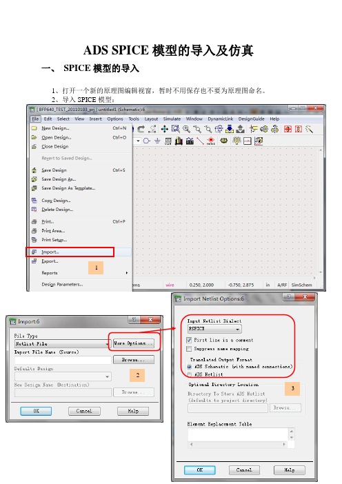
ADS SPICE模型的导入及仿真一、SPICE模型的导入1、打开一个新的原理图编辑视窗,暂时不用保存也不要为原理图命名。
2、导入SPICE模型:1233、新建一个原理图,命名为“BFP640_all ”,利用刚导入的SPICE 文件并对照下载的SPICE 文件附带的原理图进行连接:导入完成! 已经导入了: bfp640.dsn chip_bfp640.dsn sot343_bfp640.dsn 等文件。
选择要导入的SPICE 模型文件 4连接好后的BFP640_all原理图如下:4、为SPICE模型创建一个新的电路符号ADS原理图系统默认的电路符号如下:这里我们为BFP640创建一个新的NPN电路符号。
1、在原理图设计窗口中的菜单栏中选择【View】→【Create/Edit Schematic Symbol】命令中,出现“Symbol Generator”对话框后,单击【OK】按钮,出现如上图所示的默认符号;2、在菜单栏中选项【Select】→【Select All】命令,并单击【Delete】按钮删除默认符号;3、在菜单栏中选择【View】→【Create/Edit Schematic Symbol】命令回到原理图设计窗口;4、在原理图设计窗口中选择【File】→【Design Parameters】,打开“Design Parameters”对话框;5、按照下图所示,设置对话框中的参数单击【OK】按钮,保存新的设置并自动关闭对话框;6、最后,单击【Save】按钮保存原理图,电路符号就创建完成。
二、直流仿真1、在ADS主视窗下单击【File】→【New design】,在弹出的对话框中输入新原理图名称“BFP640_DC1”,并选择“BJT_curve_tracer”设计模版,如下图所示:文件描述元件名称Q在下拉菜单中选择ADS内建模型SYM_BJT_NPN选择元件封装单击【OK】按钮后,将弹出已经带有DC仿真控件的原理图。
spice仿真

spice仿真简介Spice(Simulation Program with Integrated Circuit Emphasis)是一种电路仿真软件,广泛应用于电子工程领域。
它可以模拟电路中的各种元件和信号,提供了丰富的仿真功能,能够准确地预测电路的行为和性能。
spice软件特点Spice软件具有以下主要特点:1.模型库丰富:Spice软件提供了各种各样的元件模型,包括传输线、电阻、电容、电感、二极管、晶体管等。
用户可以根据自己的需要选择合适的元件模型,进行仿真分析。
2.仿真精度高:Spice软件采用了复杂的数学算法,能够对电路进行准确的仿真计算。
它能够考虑到电路中各种元件的非线性特性,并给出准确的仿真结果。
3.仿真速度快:Spice软件在运行时采用了高效的算法和优化技术,提高了仿真的速度。
用户可以在较短的时间内得到仿真结果,提高工作效率。
4.灵活性强:Spice软件具有丰富的仿真选项和参数配置功能,能够满足不同用户的需求。
用户可以通过调整参数来改变仿真条件,观察电路的行为和性能变化。
5.支持多平台:Spice软件在设计上具有良好的可移植性,能够在不同操作系统上运行。
用户可以根据自己的实际情况选择合适的操作系统进行仿真。
spice仿真流程Spice仿真的基本流程如下:1.定义电路元件:首先,用户需要定义电路中的元件,包括电阻、电容、电感、二极管、晶体管等。
可以通过编辑器或文本方式进行定义。
2.建立电路拓扑:用户需要根据实际电路设计,在编辑器中建立电路的拓扑结构。
可以使用类似于网表的方式描述电路的连接关系。
3.设置仿真参数:用户需要设置仿真的参数,包括仿真时间、仿真步长等。
可以根据需要进行适当的调整。
4.运行仿真:用户可以直接运行仿真,Spice软件会根据定义的电路元件和参数进行仿真计算,并得出仿真结果。
5.结果分析:用户可以通过仿真结果进行电路性能分析,比如电压波形图、电流曲线等。
可以根据需要调整仿真参数,再次进行仿真,以达到理想的仿真效果。
第2讲.SPICE语言与电路仿真
模 型 类 别 总 结
IND CORE D NPN PNP NJF PJF NMOS PMOS GASFET
23
SPICE基本语句 TYPE VSWITCH ISWITCH 关键字 S W N O U U U U U U U U 元件名称 电压控制开关 电流控制开关 数字输入器件 数字输出器件 数字输入输出模型 标准门 三态门 边缘触发器 门控触发器 脉宽校验器 复位和保持校验器 数字延迟线
8
SPICE基本语句
SPICE输入描述语句的构成
标题语句 描述文件的第一行。SPICE将第一行作为标题行打印而不作为 电路的一部分进行分析。 注释语句 一般形式是“ * ”后加字符串。注释语句不参与电路的模拟仿真。 可以存在于输入文件除第一行和最后一行之间的任何位置。
9
SPICE基本语句 电路的描述语句 定义电路拓扑结构和元件类型及其数值,半导体器件,电路描 述语句等。可以出现在文件的第二行到末行结束语句之间的任 何地方。 电路特性分析和控制语句 可以对对电路的特性进行选择分析,如分析频率特性等,以及 对输出等要求的控制语句。 结束语句 标志着电路描述语句的结束。 格式: “ .END”,位于描述语句文件的最后一行。
模 型 类 别 总 结
DINPUT DOUTPUT UIO UGATE UTGATE UEFF UGFF UWDTH USUHD UDLY
24
SPICE基本语句
电源和信号源
电压源、电流源可以是独立源,也可以是受控源。一个独立源可 以是直流源、交流小信号源或瞬态源。其中瞬态源又有正弦SIN、 脉冲PULSE、指数EXP、分段线性PWL和单频调频SFFM源等几 种形式。源描述语句由源名称、连接关系和源数值组成。 独立电压源语句格式 V(name) N+ N- [<DC> value] +[AC <magnitude value> <phase value) >] +[(transient value) +<PULSE> <SIN> <EXP> <PWL> <SFFM>]
第7章 SPICE模型及仿真

固定负载,扫描管子尺寸
P110
…… .param wu=1.2u .param wpt='2.5*wu' …… .data cv wpt 1.2u 2.4u 3u .enddata X1 IN 1 INV WN=wu WP=wpt X2 1 2 INV WN=wu WP=wpt X3 2 OUT INV WN=wu WP=wpt CL OUT 0 1pf …… .TRAN 1N 200N sweep data=cv .measure tran td trig v(in) val=2.5 td=8ns +rise=1 targ v(out) val=2.5 td=9n fall=1 .END
3 互感 M
格式: KXXXX LYYYY LZZZZ VALUE
例句:
K43 L3 L4 0.99
7.2 电路元件的SPICE输入语句
4 理想传输线
格式: TXXXX N1 N2 N3 N4 Z0=VALUE
(TD=VALUE) (F=FREQ(NL=NRMLEN)) + (IC= V1,I1,V2,I2) 例句: TIN 1 0 2 0 Z0=50 TD=100PS
设计基本反相器单元
根据模型参数、设计要求设定管子尺寸
写出反相器网单:
.TITLE 1.2UM CMOS INVERTER CHAIN .INCLUDE "models.sp" .global vdd
Hale Waihona Puke Mn out in 0 0 NMOS W=1.2u L=1.2u
Mp out in vdd vdd PMOS W=3u L=1.2u CL OUT
SPICE电路仿真软件应用入门
编辑课件ppt
30
附录:仿真电路练习题
1. cfqi 乘法器 2 . fa3 负反馈放大器 3. fa3-H 红外感应开关1 4 . FBSG 互补振荡电路 5. FDZ 放大子电路 6. FDZ2 放大块 7. fzqi 负阻振荡器8. gz 高频振荡器 9. hwx红外感应开关0 10. lb 滤波器 11. LB0滤波子电路 12. LB1滤器块 13. lba喇叭分频器 14. LM324 LB运放带宽滤波器 15. LM324 运放方波发生器 16. sd 双灯闪光电路 17. T5 耦合电路18. T 7 运放振荡电路 19. wy 稳压管测试电路 20. wydy 滤波电路设计 21. why 信号源 22. wyq 微音器 23. fa3-H2 红外感应开关 24.ycsb 亚超声波开关 25. T6 选频放大器
编辑课件ppt
31
(VOLTS/UNIT)
(VOLTS/PERCENT)
R_R2
1.000E+03 -1.320E-09 -1.320E-08
R_R3
1.000E+04 4.282E-06
4.282E-04
R_R1
1.000E+05 -6.925E-07 -6.925E-04
R_R4
1.000E+02 2.914E-12
选中元件 选中单个元件 选中多个元件
移动元件 移动单个元件 移动多个元件
调整元件方向 旋转:Ctrl R 反向:Ctrl F
电子设计中的SPICE仿真技术

电子设计中的SPICE仿真技术在电子设计中,SPICE仿真技术是一种非常重要的工具,它可以帮助工程师在设计电路之前进行准确的分析和验证。
SPICE(Simulation Program with Integrated Circuit Emphasis)是一种用于模拟电路行为的通用工具,通过模拟电路中的元件和信号传输来预测电路的性能和稳定性,从而节省了设计成本和时间。
在进行电子设计中,SPICE仿真技术可以帮助工程师进行以下方面的工作:1. 电路分析:SPICE仿真技术可以帮助工程师分析电路中各个元件的工作状态、电压、电流等参数,从而帮助工程师了解电路的整体工作情况,有助于发现潜在问题并进行优化。
2. 参数优化:在设计电路时,工程师可以通过SPICE仿真技术来寻找最佳的元件数值,使得电路性能达到最佳状态,比如最小功耗、最大增益等。
3. 稳定性分析:SPICE仿真技术可以帮助工程师分析电路的稳定性,如相位裕度、阻尼比等,避免在实际使用中出现振荡等问题。
4. 故障分析:通过SPICE仿真技术,工程师可以分析电路中的故障原因,比如元件烧坏、短路等,从而快速定位并解决问题。
5. 产品验证:SPICE仿真技术可以帮助工程师在设计阶段对产品进行验证,模拟出实际工作环境中可能出现的情况,从而提前发现问题并改进设计。
在使用SPICE仿真技术时,工程师需要注意以下几点:1. 选择合适的SPICE软件:目前市面上有多种SPICE仿真软件可供选择,如LTspice、OrCAD、PSpice等,工程师需要根据自己的需求和熟悉程度选择适合的软件。
2. 模型准确性:在进行SPICE仿真时,工程师需要确保所选用的元件模型和参数准确无误,以保证仿真结果的准确性。
3. 参数设置:工程师在进行SPICE仿真时,需要合理设置仿真参数,如仿真时间、步长等,以确保仿真过程的准确性和效率。
4. 结果分析:工程师在进行SPICE仿真后,需要对仿真结果进行详细的分析,从而得出关键问题和优化方案。
Spice仿真介绍和操作

数字逻辑基础LOGOEDA工具在数字逻辑课程中的应用--Multisim工具之Spice仿真在模拟电子课程中,我们通过使用晶体管的小信号模型,手工计算得到小规模模拟电子电路电压增益、电流增益、输入阻抗、输出阻抗、频率响应特性等。
⏹这种通过人工计算的分析方法就显得效率很低。
⏹随着计算机性能的不断提高,电子设计自动化(ElectronicDesign Automation,EDA)工具出现。
它成为电子系统设计和分析的强有力的助手。
⏹EDA工具取代了传统的手工计算方法,显著的提高了设计电路和分析电路的效率。
EDA工具在数字逻辑课程中的应用--Multisim工具之Spice仿真以集成电路为重点的仿真程序(Simulation Programwith Integrated Circuit Emphasis,SPICE),它是为了执行日益庞大而复杂的集成电路仿真工业而发展起来的,它是一个通用的、开源的模拟电子电路仿真工具。
⏹SPICE是一个程序用于集成电路和板级设计,用于检查电路设计的完整性,并且预测电路的行为。
⏹SPICE最早由加州大学伯克利分校开发,1975年改进成为SPICE2的标准,它使用FORTRAN语言开发。
在1989年,Thomas Quarles 开发出SPICE3,它使用C语言编写,并且增加了窗口系统绘图功能。
EDA 工具在数字逻辑课程中的应用--Multisim 工具之Spice 仿真在目前流行的NI 公司的Mutisim Workbench 工具、Altium 公司的Altium Designer 工具和Cadence 公司的OrCAD 工具中都嵌入了SPICE 仿真工具。
⏹在SPICE仿真工具中,包含下面的模块:☐电路原理图输入程序。
☐激励源编辑程序。
☐电路仿真程序。
☐输出结果绘图程序。
☐模型参数提取程序。
☐元器件模型参数库。
下面将通过Multisim 环境下的设计实例,演示EDA工具在数字逻辑课程中的应用--Multisim工具之Spice仿真SPICE的基本分析功能包含三大类:⏹直流分析⏹交流分析⏹时域分析EDA工具在数字逻辑课程中的应用--Multisim工具之Spice仿真注1:直流分析是所有其它分析的基础。
Spice仿真
(5)运行Pspice。执行Pspice/Run命令。
(6)查看分析结果。 分析计算结束后,系统自动调用Probe模块,屏幕上出现 如图所示的Probe窗口。
在Probe窗口中,执行 Trace/Add Trace命令, 出现Add Trace 对话框。
可用以下两种方法选择要显示的变量名:
① 在对话框左边的输出变量列表中用光标点中要显示的变量名, 该变量名即出现在下端的“Trace Expression”文本框中,允 许同时点选多个输出变量。 ② 在“Trace Expression”
返回
元器件属性参数编辑
Capture自动为每个元器件设置一个元件名和参数值,元 器件设置不符合要求时,可对元器件参数进行编辑
(1).元器件群的参数编辑。选中所有要编辑的元器件。然后点击鼠标右键,调 出快捷菜单,选择执行Edit Properties 命令,即可开启该元器件群的属性编辑 对话框,点击对话框左下方的Part按钮,便可更改各元器件的名称和参数。 (2).单个元件的参数编辑。双击该元件,即出现对话框。在Value文本框中键入 新值即可。同时可以修改该元件电路图中的显示格式(Display Format)、字 体(Font)、颜色(Color)和放置位置(Rotation)等。
SPICE仿真及分立元件电路实验
目的: 1. 学会仿真软件使用,熟练掌握PSPICE9.2 的基本操作 2. 学习利用仿真手段分析设计电子电路
Spice仿真
软件简介 仿真步骤 放大电路各种性能指标的仿真方法 实验内容
OrCAD/PSpice9软件组成
1、 Capture CIS 模块:电路原理图设计软件。除可生成各类 模拟电路、数字电路和数/模混合电路的电路原理图外,还配 备有元器件信息系统CIS(Component Information System), 可以对元器件的采用实施高效管理。 2、PSpice 模块:通用电路模拟软件。除可对模拟电路、数字 电路和数/模混合电路进行模拟外,还具有优化设计的功能。 该软件中的Probe模块,不但可以在模拟结束后显示结果信号 波形,而且可以对波形进行各种运算处理,包括提取电路特性 参数,分析电路特性参数与元器件参数的关系。
SPICE电路仿真软件应用入门PPT课件

品中是十分难得的。 认识一下
3.System View电子系统仿真软件。
5
EWB电路设计仿真工作站介绍
6
Multisim 2001电路仿真软件介绍
产品界面
7
Multisim 2001电路仿真软件介绍
8
TINA电路设计仿真软件介绍
9
1.5 本次学习的目的要求
1.能够用PSPICE正确地绘制电路原理图。 2.能基本正确地进行仿真设置,并得到
3
1. 电路仿真的意义和作用
1.3 电路仿真的主要作用
1.验证电路设计方案的正确性; 2.优化电路设计; 3.电路性能的模拟测试等。
4
1.4 仿真软件介绍
目前比较流行的电路仿真软件主要有
1.PSPICE (Simulation Program with Integrated Circuit Emphasis)电 路仿真软件。
R_R3
1.000E+04 4.282E-06
4.282E-04
R_R1
1.000E+05 -6.925E-07 -6.925E-04
R_R4
1.000E+02 2.914E-12
2.914E-12
V_V3
0.000E+00 0.000E+00
0.000E+00
V_V2
1.200E+01 -9.939E-01
30
附录:仿真电路练习题
1. cfqi 乘法器 2 . fa3 负反馈放大器 3. fa3-H 红外感应开关1 4 . FBSG 互补振荡电路 5. FDZ 放大子电路 6. FDZ2 放大块 7. fzqi 负阻振荡器8. gz 高频振荡器 9. hwx红外感应开关0 10. lb 滤波器 11. LB0滤波子电路 12. LB1滤器块 13. lba喇叭分频器 14. LM324 LB运放带宽滤波器 15. LM324 运放方波发生器 16. sd 双灯闪光电路 17. T5 耦合电路18. T 7 运放振荡电路 19. wy 稳压管测试电路 20. wydy 滤波电路设计 21. why 信号源 22. wyq 微音器 23. fa3-H2 红外感应开关 24.ycsb 亚超声波开关 25. T6 选频放大器
SPICE仿真实验报告

2SPICE 仿真实验报告一、实验目的(1)联系使用标准SPICE 的元件描述语句,分析语句,输出语句,模型语句等,熟练掌握电路元件的编写;(2)能够根据电路分析的具体要求灵活使用SPICE ;(3)练习使用aim-SPICE 软件,特别是其中的标准SPICE 分析功能。
二、实验设备:aim-SPICE Student Version3.8a 软件。
三、实验内容:1、实验7-1:解直流电路习题1已知参数求直流电流I :I=-15A 电路文件如下:分析结果如下:2、实验7-2:解直流电路习题2First circuitV1 0 1 DC 150V2 0 3 DC 120V3 1 4 DC 120R1 0 2 10R2 1 2 10R3 2 3 4R4 3 4 10.OP.END32104已知部分参数,求电源扫描参数:V-2~6V电路文件如下: 扫描电压变化曲线如下:3、实验7-3:解交流电路习题已知参数求交流响应:电流i 以及电压u 的波形:电路文件如下:电流及电压波形图如下:Third circuitSecond circuit Vi 1 0 DC Is 0 3 DC 5R1 0 1 4R2 0 2 3R3 2 3 2R4 2 4 2Vmeas 4 1 DC 0.DC Vi 2 6 0.01.PLOT DC i(Vmeas).END1234Vmeas1234Vmeas5V 0 1 sin(0 220√2 159 0 0 -45)R1 0 2 100R2 0 4 200R3 2 3 50C 4 1 5u L1 1 2 0.1L2 4 5 0.5Vmeas 3 5 DC 0.tran 0.2m 110m 100m .PLOT tran V(1) i(Vmeas).END4、实验7-4已知文桥参数求幅频特性以及相频特性曲线电路文件如下: 频率曲线如下: 幅频特性曲线:231相频特性曲线:Fourth circuit Vi 1 0 ac 1R1 1 3 100R2 0 2 100C1 3 2 20u C2 2 0 20u.ac DEC 20 1 1E6.PLOT ac vdb(2).PLOT ac vp(2).END5、实验7-5:RC 电路的一阶过渡过程已知一阶电路参数求阶跃响应;电路文件如下: u (ab )过渡过程波形6、实验7-6:RLC 串联电路的二阶过渡过程Fifth circuitV 1 0 PWL(0 0 1E-20 12 60m 12 60m+1E-20 0)R1 1 2 6K R2 2 0 6K R3 2 3 3K C 2 0 2u IC=0.tran 0.01m 100m .PLOT tran V(2).END123已知二阶电路参数求阶跃响应;电路文件如下: 电流i 的波形:7、实验7-7:画二极管伏安特性曲线已知二极管参数,求二极管的伏安特性曲线;电路文件如下: 二极管伏安特性曲线如下:Seventh circuit Vd 1 0 DCSixth circuitV1 0 1 PWL(0m 0 1E-20m 10 100m 10)R1 0 3 5L 2 3 0.1C 2 4 100u Vmeas 4 1 0.tran 0.1m 100m .PLOT trani(Vmeas).END12034Vmeas1Vmeas 1 2 DC 0D 2 0 1N41418.model 1N41418 D(+IS=0.1E-12 RS=16CJO=2E-12 TT=12E-9BV=100 IBV=0.1E-12).DC Vd 0 1.2 0.01.PLOT DC i(Vmeas).END8、实验7-8:画三极管的输出特性曲线231。
SPICE 仿真和模型简介
SPICE 仿真和模型简介1、SPICE 仿真程序电路系统的设计人员有时需要对系统中的部分电路作电压与电流关系的详细分析,此时需要做晶体管级仿真(电路级),这种仿真算法中所使用的电路模型都是最基本的元件和单管。
仿真时按时间关系对每一个节点的I/V 关系进行计算。
这种仿真方法在所有仿真手段中是最精确的,但也是最耗费时间的。
SPICE(Simulation program with integrated circuit emphasis)是最为普遍的电路级模拟程序,各软件厂家提供提供了Vspice、Hspice、Pspice 等不同版本spice 软件,其仿真核心大同小异,都是采用了由美国加州Berkeley 大学开发的spice 模拟算法。
SPICE 可对电路进行非线性直流分析、非线性瞬态分析和线性交流分析。
被分析的电路中的元件可包括电阻、电容、电感、互感、独立电压源、独立电流源、各种线性受控源、传输线以及有源半导体器件。
SPICE 内建半导体器件模型,用户只需选定模型级别并给出合适的参数。
2、元器件模型为了进行电路模拟,必须先建立元器件的模型,也就是对于电路模拟程序所支持的各种元器件,在模拟程序中必须有相应的数学模型来描述他们,即能用计算机进行运算的计算公式来表达他们。
一个理想的元器件模型,应该既能正确反映元器件的电学特性又适于在计算机上进行数值求解。
一般来讲,器件模型的精度越高,模型本身也就越复杂,所要求的模型参数个数也越多。
这样计算时所占内存量增大,计算时间增加。
而集成电路往往包含数量巨大的元器件,器件模型复杂度的少许增加就会使计算时间成倍延长。
反之,如果模型过于粗糙,会导致分析结果不可靠。
因此所用元器件模型的复杂程度要根据实际需要而定。
如果需要进行元器件的物理模型研究或进行单管设计,一般采用精度和复杂程度较高的模型,甚至采用以求解半导体器件基本方程为手段的器件模拟方法。
二微准静态数值模拟是。
- 1、下载文档前请自行甄别文档内容的完整性,平台不提供额外的编辑、内容补充、找答案等附加服务。
- 2、"仅部分预览"的文档,不可在线预览部分如存在完整性等问题,可反馈申请退款(可完整预览的文档不适用该条件!)。
- 3、如文档侵犯您的权益,请联系客服反馈,我们会尽快为您处理(人工客服工作时间:9:00-18:30)。
● 可变电阻: VALUE=100K,SET=0.5
● VSIN信号源:AC=30mv、VOEF=0v、
FREQ=1kHz、VAMPL=30mv。
● 三极管参数设置方法1:
选择菜单Edit/Pspice Model ;
改参数 bf 为140,保存。
11
四、 设置仿真分析类型(Pspice/New Simulation)
5
1. 创建工程项目文件
• 选择Create a blank pro, OK
6
1. 创建工程项目文件
工程项目管理器
绘图工作面
• 出现图示界面,完成创建工程项目文件 7
2. 画原理图—(1) 调元件
• 菜单Place/ Part,或图标,打开元件库 • 添加元件库 Add Lib__Analog 、Bipolar 、Source • 提取元件
限幅区对应的VC、Vid值 (5)测量Rid、AVD、AVC 及KCMR (6)对Rid、AVD、KCMR 进行误差分析
22
四、实验要求
3、BJT特性曲线仿真(选做P55) (1)验证BJT输出特性曲线 (2)验证BJT输入特性曲线 实验要求见P52.
画线:将光标移到需要连线的起点,单击左键(此
时会拖着1根线);移动鼠标到所需位置,单击左键, 如此循环,直到连线的终点(某元件的引脚)。
结束:单击鼠标右键结束 移动、旋转和删除:与元件操作相同
10
三、修改元器件标号和参数
方法1:选中元器件,选择菜单中Edit/Attributes 方法2:双击该元件符号 方法3:双击参数文字
3. 设置仿真分析类型 4. 仿真分析5. 查看仿真输出结果
从输出文件中查看仿真结果__文本结果 用Probe程序观测__ 图形结果
4
以“单级共射放大电路”为例
三、Pspice仿真举例
1. 创建工程项目文件
• 在D盘下,建 立子目录
• 目录名和文件 名不能有汉字、 空格等!
• 选择Analog or Maxed A/D
• 其他步骤与“输入电阻的频率响应”分析相同 • Ro – V(Vo)/I(Vs)
仿真结束! 20
四、实验要求
1、单管共射电路设计(P88) (1)在Schematics中画出已设计好的电路电路图 (2)测量静态工作点:IB、IC、VBE、VCE (out文件) (3)观测输入、输出电压波形,并计算电压增益Av (4)观测幅频响应曲线:db(V(Vo)/V(Vs:+))
• Trace/Add 键入V(Vs:+), V(Vo), 看波形。
16
—波形和曲线结果
• 击活AC Sweep, Pspice/Run • 观测幅频响应曲线:
– Trace/Add: db(V(Vo)/V(Vs:+)) – Trace /Cursor/Display激活游标测中频增益 – 用游标找到增益下降3dB ,对应频率为上限频率或下限
实验3、Pspice仿真1 ——单级共射放大电路
一、Orcad功能简述 二、Pspice仿真步骤 三、Pspice仿真举例 四、实验要求1来自一、Pspice软件功能
1. 仿真功能:
(1)静态工作点分析 (2)瞬态分析(时域分析) (3)交流小信号分析(频域分析) (4)直流扫描分析 (5)直流小信号传递函数值分析 (6)直流小信号灵敏度分析 (7)统计特性分析(蒙特卡罗分析和最坏情况分析)
频率
• *观测相频响应曲线: Vp(Vo)-Vp(Vs:+) • 观测输入电阻的频率响应:
– Trace/Add: Ri = V(Vi)/I(Vs) – Trace /Cursor/Display激活游标测中频输入电阻
17
18
19
求解输出阻抗
• 修改电路:
–号令源VsV=S0,IN信(40号0m源v短) 路,取掉负载RL,外加一个信
Points/Decade 101
Logarithmic选: Decade
单击应用,确定返回。
13
五、保存和自动检查
• 保存 • 进行电路规则检查、建立网表文件(*.net) :
Pspice/Create netlist
• 若有问题,屏幕会有指示 • Windows/Session Log弹出错误提示窗口
输出文件更详细
1. 静态工作点分析
12
四、 设置仿真分析类型
2. 瞬态分析(时域分析)Transient
Run to 4ms Start saving data 0ms Maximum step 20us 单击应用,确定返回。
3.交流小信号分析(频域分析)AC Sweep
Start 10Hz
End 100Meg
测中频增益、上限频率和下限频率 相频响应曲线:Vp(Vo)-V(VS:+) (5)观测输入电阻的频率响应:Ri -- V(Vi)/I(Vs) (6)观测输出电阻的频率响应:Ro-- V(Vo)/I(Vs) (7)观察非线性失真现象
21
四、实验要求
2、单端输入单端输出差分放大电路仿真(选做P95) (1)设计单端输入单端输出差分放大电路 (2)在Schematics中画出电路图 (3)测量静态工作点(out文件) (4)观测差模传输特性曲线,标出线性区、非线性区及
8
(2)元件移动、旋转和删除
选中元器件:
用鼠标左键单击,此时元器件变为红色
移动:压住鼠标左键拖到合适位置,松开鼠标左键 旋转:菜单Edit/Rotate(或快捷键Ctrl+R) 翻转:菜单Edit/mirror 删除:选择菜单Edit/cut ;或按键Delete
9
(3)画线
进入:菜单Place/wire或工具栏的
14
六、仿真—文本结果
• 在工程管理项
目 器 Pspice Resource中
• 击 活 Bias , 鼠 标 右 键 Make
Active
•菜
单
Pspice/Run
• 查看文本输出
Pspice/view output file, 或
输出文本文件
15
—波形和曲线结果
• 击活Transient, Pspice/Run
2
2.Pspice软件结构
Orcad 集成环境有: • 模拟和模数混合电路仿真环境 • PCB板仿真环境 • 可编程数字逻辑器件分析设计环境
3
二、Pspice仿真步骤
1. 创建工程项目文件 2. 编辑电路原理图(画电路图)
(1)调元件(2)元件移动、旋转和删除(3)画线 (4)修改元器件标号和参数(5)保存和自动检查
