PPCL用户手册_中文版
freescale MC9S12P128中文手册

Chapter1 Device Overview MC9S12P-Family 介绍The MC9S12P 系列单片机是经过优化后有着低成本、高性能、低引脚数的汽车专业级单片机产品,该产品倾向于弥补高端16位单片及产品如MC9S12XS和低端8位单片机产品之间的空缺。
MC9S12P 主要针对于要求使用CAN 或者 LIN/J2602通讯接口的汽车应用产品,典型的应用案例包括车身控制器、乘坐人员检测、车门控制、座椅控制、遥控车门开关信号接收器、智能执行器、车灯模块、智能接线器。
The MC9S12P 系列单片机使用了很多MC9S12XS系列单片机相同的功能,包括片内闪存错误纠正代码(ECC)、一个专为数据诊断或者数据存储的单独的数据闪存模块、高速AD转换器和高频调制锁相环(IPLL)有效改善电磁兼容性能。
MC9S12P系列单片机提供的所有16为单片机优点和微处理器效率,同时保持飞思卡尔用户熟悉的8位及16位单片机,低成本,功耗,EMC和高效的代码80针QFP、64针LQFP、40针QFN封装产品,最大限度的与MC9S12尺寸的优点,如同MC9S12XS一样可以无需等待外围设备和内存的状态既可以运行16为带款的寻址,MC9S12P系列单片机主要有XS引脚兼容. I/O口在各种模式下都可以使用,同时具有中断功能的I/O口还可以在停止或等待模式下唤醒。
芯片特性表一:提供了MC9S12P家庭成员特征摘要,或D寄存器擦除或者编程需要最低总线频率为1MHZ芯片功能• S12 CPU 内核• 高达128 KB具有ECC功能的片上闪存• 4 Kbyte带ECC功能的数据闪存• 高达6 Kb片上静态存储器(SRAM)• 具有内部滤波器的锁相环倍频器 (IPLL)• 4–16 MHz 皮尔斯振荡器• 1 MHz内部RC振荡器• 定时器 (TIM) 具有16位输入捕捉、输出比较、计数器脉冲累加器功能• 具有8位6通道的脉冲调制模块(PWM)• 10通道12位分辨率的逐次逼近AD转换器• 1个串行通信外部接口(SPI)• 1个支持局域网通讯串行通信(SCI) 模块•一个多可扩展控制器区域网络(MSCAN) 模块 (支持CAN 协议B)•片上电压调节器 (VREG) 可对内部供电及内部电压整流• 自主周期中断 (API)模块特征CPUS12 CPU 是一个高速的16位处理单元:•全16-bit数据通道提供有效的数学运算和高速的数学执行• 包含很多单字节指令,可以有效的利用ROM空间• 宽域变址寻址功能:—采用堆栈指针作为所有变址操作的变址寄存器—除了在自增或自减模式下都可以利用程序计数器作为变址寄存器—使用A\B\D累加器做累加器偏移—自动变址,前递增(++a)、前递减(--a)、后递减(a--)、后递增(a++)(by –8 to +8)带ECC功能的片内闪存• 高达 128 Kb程序闪存空间— 32 位数据加7 位ECC (纠错码) 允许单字节纠错和双字节纠错— 512字节擦出扇区空间—自动编程和擦除算法—用户设置读写页面边界—具有可以防止偶然编程或者擦除的保护结构• 4 Kb 数据闪存空间— 16 位数据加6位纠错码允许单字节和双字节纠错功能— 256 字节的擦出扇区空间—自动编程和擦除算法—用户设置读写页面边界片内静态存储器高达6kb通用RAM外部晶振 (XOSC)• 闭环控制皮尔斯晶振频率为4MHZ---16MHZ—振幅增益控制输出电流—低谐波失真信号Signal with low harmonic distortion—低功耗—良好的噪声免疫—无需外部限流电阻—跨导尺寸优化提供良好的振荡器启动保证内部RC晶振 (IRC)• 可调的内部参考时钟—频率: 1 MHz—在–40°C to +125°C环境温度范围内调节精度达: %内部锁相环倍频器(IPLL)—无需外部元件—参考分频器和倍频器提供大变化量的时钟频率—自动带宽控制低频率抖动操作—自动锁定频率—可配置的选项,扩频减少电磁干扰EMC (频率调制frequency modulation)—参考时钟源:–外部 4–16 MHz 共振器/晶振 (XOSC)–内部RC晶振 1 MHz (IRC)系统支撑• 上电复位(POR)• 系统复位发生器• 非法寻址复位•低电压检测中断或复位• 实时中断 (RTI)• 计算机正常工作复位(COP) 开门狗—可通过相应窗口设置COP用以采用错误侦测复位通过位操作对闪存进行初始化复位•时钟监控器监控晶振功能正常工作定时器(TIM)• 8通道16位定时器可进行输入捕捉和输出比较• 16-bit带有7位精度预分频器的自由运行计数器•一通道16-bit 脉冲累加器脉冲带宽调制器 (PWM)• 6通道8位or 3 通道16-bit脉宽调制器—每个通道都可以对周期和占空比进行编程—中心对齐或者左对齐输出—宽频率范围内可编程逻辑时钟局域网控制器 (MSCAN)•速率达1Mbit/s, 满足CAN A, B 协议—标准和扩展数据帧— 0–8 字节长度—可编程比特率达1 Mbps•5个 FIFO(先进先出)的接收缓冲器•三个内部优先发送缓冲器• 灵活的标识符可编程选通滤波器s:— 2 x 32-bit— 4 x 16-bit— 8 x 8-bit•集成了低通滤波器的唤醒操作• 闭环反馈自检测• CAN 总线监听•总线关闭可通过软件干预或者自动恢复• 16-bit 接收发送信息时钟戳串行通信接口 (SCI)•可选择全双工或单工模式•标准的不归零格式•通过可编程脉宽调制选用 IrDA 反转归零格式• 13位波特率可选•可编程字符长度•可编程改变其接收和发送极性for transmitter and receiver •边沿触发接收唤醒•支持LIN总线的间隔检测和传输冲突检测Serial Peripheral Interface Module (SPI)•可配置 8- or 16-bit 数据大小•全双工或单线双向•全双工接收和发送• Master or slave 模式•最高位优先 or 最低位优先可换• 并口时钟频率相位和极性选择AD转换 (ATD)• 10通道12位AD转换器— 3微妙转换时间— 8-/10-/12-位解决方案—数据结果左对齐或右对齐—停止模式下使用内部晶振作为转换器晶振—低功耗模式下模拟信号比较唤醒—连续转换模式e—多通道扫描•引脚可作为IO口片内电压调节器(VREG)•具有带隙标准的线性电压稳压器• 具有低电压中断功能的低压检测器•上电复位 (POR) 电路•低电压复位功能 (LVR)•高温传感器背景调试 (BDM)• 非插入内存访问指令• 支持在线对片内非易始性存储单元编程调试器 (DBG)•64个入口跟踪缓冲器• 三个比较器 (A, B and C)—比较器A比较全16位地址总线额16位数据总线—精确寻址和寻址范围比较•两种匹配比较类型—标记位—程序强行置位该类型是在一数学公式出现后一个指令边界可用•四个跟踪模式•四个阶段状态序列发生器 stage state sequencer内部结构框图引脚图存储器映像表Table 1-2. Device Register Memory Map注意在表1-2中保留的寄存器空间不分配给任何模块,该寄存器的保留空间是留给以后使用的,对这些保留空间写操作没有任何效果,读该空间返回值都为零。
C2P ALPR集成用户手册说明书
C2P ALPRALPR to Milestone IntegrationUser MaContentsOverview (3)Introduction (3)Critical features include: (4)Installation (5)Figure 1 (5)Pre-install requirements (6)Installation Process (6)C2P Base (6)Installing the C2P Base (6)C2P Base installer component selection menu. (7)********************************************************** (7)Installing the C2P ALPR Proxy (8)Configuration (9)C2P ALPR Proxy configuration GUI (9)C2P Event Streaming Engine (ESE) GUI (13)C2P HSE Proxy GUI (14)Smart Client view setup for C2P integration (15)Troubleshooting (16)Appendix A: Sample C2P ALPR proxy log files (17)Appendix B: C2P ALPR GUI Rules Engine (18)Appendix C: CTP License Server Control Panel (19)Loading a new CTP License File (19)Contact Information (20)OverviewThis User manual is intended to be used as a reference. This manual covers all of the components used in the C2P ALPR integration. A large portion of this manual covers the configuration of Milestone components as well as the C2P components.The C2P portion of this integration can be installed in minutes and in many cases will work as shipped without any configuration needed. This manual serves as a reference for applications that go beyond a basic install of the C2P ALPR to Milestone integration.IntroductionConvergenceTP (C2P) is the market leader in bringing text and alert information from virtually any TCP/IP enabled appliance or sensor into the users Video Management System (VMS). Video surveillance is a powerful tool for security professionals, but the true benefits of video surveillance can only be realized when users have access to the data (all the data) from every TCP/IP enabled device in the customer enterprise. This Internet of Things (IoT) concept is the basis for the C2P middleware that connects the users VMS to their TCP/IP enabled devices.The value for the user when their IP appliance and sensor data is captured and stored time synchronized with the video in the video surveillance system is they now have a way to index video in their surveillance system. With the C2P Hypermedia Search Engine (HSE) users can search on text received from a Point of sale terminal, License plate reader, Access control reader, Bar code reader, RFID sensor, etc. and then watch video of that specific event as it happened. Having the data time synchronized with the surveillance video means users can then bring up a view from any camera in their video surveillance enterprise and follow the person or object of interest as it moves out of view of one camera and into view of another.Users can also setup the easy to use C2P real-time Rules Engine which allows them to flag specific events for immediate viewing, or push user defined procedures for that specific event to the VMS operators screen. The Rules engine also allows the user to push generic events to the VMS system to synchronize, annotate and bookmark the detected event within the VMS event database.Critical features include:∙ALPR text captured by C2P is time synchronized with any and all video cameras attached to the Milestone VMS.∙ALPR text can be viewed in real-time from any Milestone Smart Client.∙All ALPR text received is stored and therefore available for future back office forensics searches.∙C2P provides an intuitive and powerful Hypermedia Search Engine (HSE) for use in researching specific events.∙HSE search results provide the full text of the events that are linked to the actual Milestone stored video of the event.∙C2P provides many real-time analytic tools that users can setup to trigger on specific events of interest.InstallationFor new installations you will need both the C2P ALPR proxy installer as well as the C2P Base installers. Note: included in the C2P Base installer is the ESE, HSE, HSE Proxy and License server.Figure 1 below depicts a typical C2P ALPR deployment topology.Figure 1Note:For evaluation and demo applications all of the components listed above can be installed on the same system. Without any further configuration required.Pre-install requirementsThe PC/server used to host any of the C2P Base components needs to have i7 class processor min.1Microsoft Windows® operating system Win 7/Server 2008 or Win 8/Server 20122The machine to be used for the install needs to be relatively current with Windows Updates.Ensure that the PCs/servers used to host the ESE and HSE are time synchronized with the VMS.During the install temporarily disable any antivirus SW and drop the local firewall.Milestone Smart Client installed on the PC/Server hosting the C2P ALPR Proxy software.Internet Explorer 9 or above installed on any PC hosting Smart Client workstationsAt least 1 Universal Camera license from Milestone is needed . Defaults to 30 day demo on initial install.Ability to temporarily set UAC to off while doing the install.Smart Client “Basic” login account with valid credentialsAdministrator account for use when installing CTP softwareInstallation ProcessC2P BaseNote: Installing C2P Base for the first time may require a restart of the machine after the install completes.The C2P Base software installs all of the components needed for the C2P Base system.These components include:∙The C2P Event Streaming Engine (ESE)∙The C2P Hypermedia Search Engine (HSE)∙The C2P Hypermedia Search Engine Proxy (HSE Proxy)∙The C2P License ServerInstalling the C2P Base1)Execute the C2P Base installer. “Run as administrator”2)Follow the default selections during the C2P Base install3)Select the features being installed. See: C2P Base installer component selection menu.1 The system requirements are the minimum of what will be required for satisfactory performance; your particular needs may differ or exceed the minimum requirements listed. Your specific needs will be dependent on several factors including number of IP appliances connected, number of users, the type of connected devices and the level of usage per device.2See Figure 1 above for a definition of where each component is to be installed.Note1: You will need to run the C2P Base installer on both the PC/server hosting the Milestone Base and the PC/Server hosting the recording server(s). Once the C2P base installer is run you can then select which component you want to install.For example as shown in Figure 1 the HSE database is installed on the same hardware as theMilestone base = 192.168.1.5C2P Base installer component selection menu.Note2: The “Machine code generator” is only run on the Milestone Base PC/Server. The resultant seed code produced when the Machine code generator is run should then be cut and pasted into an *****************************.Note: Cut-n-paste the above seed text above into an email. Do not send a screenshot of the text.**********************************************************Installing the C2P ALPR Proxy1)Execute the C2P ALPR installer. “Run as administrator”2)Follow the default selectionsConfigurationIf the C2P ALPR Proxy and the C2P Base are installed on the same PC/Server then no configuration is needed to run the C2P ALPR to Milestone VMS integration. This works out nice for setting up demo systems but is not how the system is deployed in practice. Refer to Figure 1 for the expected deployment topology.Below is the C2P ALPR Proxy configuration GUIC2P ALPR Proxy configuration GUIA = ALPR Service Manual Stop and Start controls. When changes are made to the ALPR proxy GUI they can manually be loaded into the ALPR proxy service by manually stopping and then re-starting the Service or alternatively the user is prompted to have the service restarted automatically when the GUI is closed.B = View Log. This is an extremely useful real-time log file because it tells the user if the ALPR Proxy is connected to the ALPR application. This log file is the first place to look before testing anything else related to the C2P ALPR integration. See also Appendix A: Sample C2P ALPR proxy log filesC = C2P ALPR Simulator. The C2P ALPR simulator is another very powerful resource for bringing up new installations. The C2P ALPR simulator works in parallel with any traffic being sent by the ALPR system. This allows all of the components of the C2P ALPR integration to be completely tested prior to the ALPR system running or even installed. Installers can run the simulator and ensure all of the integration components are functional and then turn on or install the ALPR system.Note: Data from the C2P ALPR Simulator DOES NOT get reported in the log file described in item B above.D = Help button. Explains how to use the F1 key in the GUI to get help text for each item in the GUI.E =Device Event Directives. This table is used to assign properties to each unique ALPR LPR camera names received from ALPR. These properties are used by both the C2P ALPR proxy and the C2P Hypermedia Search Engine (HSE) during playback of LPR events.The “Virtual camera” property defines which generic camera in the recording ser ver will be used to display live exceptions defined in the Rules engine portion of the C2P ALPR proxy.The “Overlay address and Port” are optional fields that allow the user to send a copy of the LPR text received to the overlay data port of external overview camera of the LPR event.The “Playback Cameras” are the cameras that will be called up for viewing as a result of the user selecting “Show Cameras” in the Hypermedia Search E ngine (HSE). This powerful feature further ties the relevant cameras to the LPR event, giving the user overview video of the vehicle at the time of the LPR event.F = Directives Setting Control. These are the controls used to add new lines to the Device Event Directives table as well as allows the user to edit existing entries in the table.G = Milestone Smart Client. The Smart Client controls are used to provide the C2P ALPR proxy with valid Milestone client login credentials. The C2P ALPR proxy uses this login to receive the valid camera names that are assigned to these login credentials. The camera names are then available to the user for use in “Playback Cameras” portion of the Device Event Directives table.In the expanded view of the VMS Cameras GUI below you can also see that there is a log file associated with this function. The log file works extremely well and will give you the detail of why your credentials did or didn’t work. If the credentials entered in the GUI are valid then the log file gives you a list of cameras that those credentials allow you to view.The VMS Cameras button is shown below.Note: Url = IP address and port for Milestone BaseH = Advanced Setting.I = Event Streaming Engine (ESE). The ESE is normally installed on a recording server associated the ALPR LPR events. See also Figure 1J = Hypermedia Search Engine (HSE). The HSE is normally located on the server hosting Milestone Base.K = License Server. The C2P License Server is normally located on the server hosting Milestone Base.L = Rule Definition. The Rules Engine is where users can specify specific LPR data to trigger live events in the Smart Client as well as generate “Generic Events” to Milestone Base. When the “Show All Events” check box directly under the Rules Definition list box is not checked then ONLY the events defined in the Rule Definition list will be shown as live events in the Smart Client. This is done to limit the amount of LPR traffic sent to the Milestone client to allow the user to see just the critical events happening live. If this is not done the amount to LPR event data being sent by the ALPR LPR cameras can make it nearly impossible to see specific events of interest.All data received from the ALPR LPR system is stored for future viewing in the Hypermedia database so no LPR events are ever lost. The “Show All Events” checkbox has no effect on what is being stored in the Hypermedia database. See also Appendix B (C2P ALPR GUI Rules Engine)M = Edit Procedure. This feature allows the user to create their own text annotation that is displayed as a camera view in the Milestone client in real-time as the LPR event is triggered by the Rules Engine. The procedure can also be setup to generate a Generic Event to the Milestone System if the procedure “Type” is set to “Alert”. The Generic Event sent to Milestone will use the “Name” o f the procedure as the Generic Event text.In the example below the Generic Event sent to Milestone when this event occurs will be “ElsagP roc1b” as specified in the “Name” field of the Procedure.Note: Anytime a procedure is edited or created you must sele ct “Yes” when prompted while closing the procedure manager to allow the ESE to be restarted. The ESE reads in the procedures on a re-start.C2P Event Streaming Engine (ESE) GUIThe ESE Control Panel/Log file provides real-time feedback as to what the C2P Proxy is sending the VMS as live LPR text images to be displayed in the Smart Client. (Including procedures)The “Config” button on the bottom of the ESE control panel brings up some configuration settings for the ESE. For non-demo installations the 2 settings that will likely need to change are identified below.The Generic Event IP address as well as the C2P License Server IP address both are normally located on the Milestone Base system. See also Figure 1C2P HSE Proxy GUIThe HSE Proxy GUI contains the configuration needed for the C2P ALPR Proxy to send LPR data to the C2P Hypermedia Search Engine (HSE)In most cases the user never needs to open the HSE Proxy GUI as all of the defaults work as installed as long as the HSE Proxy is installed and the same machine as the HSE = normal case.Reasons to use this GUI would be1)If the user wanted to change the default Password used by the HSE2)If the user wanted to change the HSE database retention time from the default 30 days.Note:If “Hours to Clear Database” is zero as shown below then the database is never cleared.Otherwise if a non-zero number is used then that number represents how often the database is truncated to the selected number of days specified in “Database Retention Days”3)If the user wants to verify that data is actually being sent to the HSE database. For this they could look atthe HSE Proxy Log file as shown below.Smart Client view setup for C2P integrationC2P uses a common Smart Client view for all C2P integrations. The view is a 1 + 3 view with the Hypermedia Search Engine (HSE) being in the “1” view and the “3” corresponds to the 3 camera views that are to the immediate right of the HSE view.Below is a screenshot of the 1 +3 view setup screen in the Smart Client.The HSE uses the Web portal for its view.The URL used = http://IP_Adr:8989 Below this is shown as http://192.168.1.19:8989The cameras are simply drag and drop from the Camera tab.Note: The default HSE login password is Password1. To change the password see C2P HSE Proxy GUITroubleshootingIn the event that your install doesn’t work as planned, or your system stops working at some point, below are some basic troubleshooting tips.If you are not seeing metadata events being reported in the VMS client, the first thing you need to do is move to the point in the system where the data first enters the C2P integration.This is where most people get hung up.In troubleshooting the rule is:“T he output device is great for alerting you that there is a problem, but that’s all it is good for.”As with troubleshooting any electronic device the same basic principles apply = start at the source and work your way through the system to determine where the data goes bad.Look for things like a blocked port (firewalled) or wrong IP Address specified in one of the C2P settings GUIs.The block diagram below shows where all of the C2P software components are located with the source located on the machine hosting the ALPR Application. This is the starting point, and most likely where the problem resides. The first thing that you want to do is to verify that the C2P ALPR Proxy is receiving data from the ALPR application. Check the C2P ALPR Proxy log file first to verify that the C2P proxy is actually receiving data from the ALPR application. The process of checking the log is simple as was illustrated earlier in this User Manual See item “B” in C2P ALPR Proxy configuration GUI and also Appendix A: Sample C2P ALPR proxy log filesEach of the other C2P software components shown below all have their own respective Log Files as explained in each of their respective sections of this manual. Use the log files first when troubleshooting.That’s what they are there for.Appendix A: Sample C2P ALPR proxy log filesThis first screenshot is a log trace of a valid connection between the C2P ALPR proxy and te ALPR applicatio. Each ALPR proxy has a log file on the front end of the proxy to log every ALPR received.If nothing is being received by this log file then nothing is being sent by the ALPR application.The screen below show what to expect if no connection can be made by the C2P proxy to the ALPR applicationAppendix B: C2P ALPR GUI Rules EngineThe C2P Rules engine allows users to create their own rules based on the Live text received from the LPR system. These rules are evaluated for each LPR read sent from the LPR system to the C2P integration.The GUI for the Rules Engine makes it very easy to add, delete or edit a rule. The Rules GUI provides dropdown selections for adding field names. Rules can be a single expression or several expressions AND’d together. Rules can push procedure for immediate viewing on the Milestone Smart Client. Rules can be sent Milestone or other 3rd party applications TCP/IP Generic event text.Appendix C: CTP License Server Control PanelTo see the CTP License Server Control Panel you need to be on the machine hosting Milestone Base.To view the Control Panel you can “Run as administrator” the CTP License Server desktop icon. See below.If the CTP License Server icon is not on the desktop you can also run the executable in:C:\ConvergenceTP\License serverThe License Server Control Panel is where real-time licensing information is displayed.Loading a new CTP License FileYou can also load in your purchased license files using the “Register” button on the bottom of the p anel.If you do Register a new license using the Control Panel BE SURE TO STOP AND START THE CONTROL PANEL afterwards.Note: The new license is not read in until the License Server service is restarted so it’s important to stop then start the service usi ng the “Stop” button below, which turns into a “Start” button once the service has stopped.Also shown below is what the Control Panel looks like when a demo license expires and then a valid license is loaded using the Register button process. The valid license was loaded in at 4:30:18 PM.Contact InformationConvergenceTPPO Box 3713Danbury, CT 06813Website Sales Support *************800.252.6840 x 1 Technical Support ***************800.252.6840 x 2。
简易操作手册@PowerGSP

普升医药物流管理系统快速入门指南湖南普升软件科技有限公司目录一、前言 (1)1.1。
票据参数 (1)1。
2. 业务参数 (1)二、功能概览 (2)2。
1。
功能模块 (2)三、业务流程 (3)3。
1.品种资料维护 (3)3.2。
往来单位资料维护 (4)3.3.采购管理 (4)3。
3。
销售管理 (5)3.3.仓库管理 (7)3。
3。
财务管理 (8)3.3.质检管理 (8)四、基础操作 (9)4.1。
甩掉鼠标 (9)4。
2。
快捷启动 (9)五、增加机构 (10)5。
1.为什么增加机构 (10)5。
2.增加机构的步骤 (10)六、票据格式导入 (11)一、前言此操作指南主要目的用于指导系统操作人员进行业务流程操作.系统业务操作流程大部分可以通过系统参数进行控制,控制中心主要有两个机构票据参数和机构业务参数:机构票据参数主要用于控制系统流程,机构业务参数主要用于控制操作细节。
1.1. 票据参数票据参数请在系统管理员的指导下进行设置,否则可能会影响业务流程的正常运转!票据参数:【供应链管理】→【业务初始设置】→【机构参数】→【机构票据参数设置】如图:1.2. 业务参数业务参数:【供应链管理】→【业务初始设置】→【机构参数】→【机构业务参数设置】如图:二、功能概览2.1。
功能模块三、业务流程3。
1。
品种资料维护通过【品种资料管理】→【品种资料管理】→【品种资料维护】打开品种资料维护界面。
品种资料维护界面主要用于新增、修改、删除公司经营的所有药品资料.品种资料可以支持商品类别、功效类别、品牌类别、存货类别、供应商类别等多种类别.通过【质量管理系统】→【质量档案】→【品种首营制表】找到增加的品种,对品种进行首营通过【质量管理系统】→【质量档案】→【品种质量档案归档】找到增加的品种,对品种相关档案进行归档。
3。
2.往来单位资料维护通过【单位资料管理】→【往来单位资料】→【单位资料维护】打开单位资料维护界面.单位资料维护包括对供应商、客户、厂家的资料的新增、删除、修改。
CorteMLPC用户手册中文版

z 其它外设: - 多达 42 个通用 I/O(GPIO)引脚,上拉/下拉电阻可配置; - 一个引脚具有 20mA 的高电流驱动能力; - 2 个 I2C 总线引脚在 Fast-mode Plus 模式下具有 20mA 的高电流汲入能力; - 4 个通用定时器/计数器,共有 4 个捕获输入和 13 个比较输出; - 看门狗定时器(WDT); - 系统节拍定时器;
1
1
8 HVQFN33
1
2
8
LQFP48
1
2
8
PLCC44
图 1.1 LPC111x 方框图 注:只适用 LQFP48/PLCC44 封装的器件。
LPC1100 系列微控制器用户手册
©2008 Guangzhou ZLGMCU Development CO., LTD. 44
广州周立功单片机发展有限公司
LPC111x 的外设包括:高达 32kB 的 Flash、8kB 的数据存储器、一个 Fast-mode Plus 的 I2C 接口、一个 RS-485/EIA-485 UART、2 个 SSP 接口、4 个通用定时器,以及多达 42 个通 用 I/O 引脚。
1.2 特性
z ARM Cortex-M0 处理器工作在 50MHz 的频率下; z ARM Cortex-M0 处理器内置有嵌套向量中断控制器(NVIC); z 32kB(LPC1114)、24 kB(LPC1113)、16kB(LPC1112)或 8kB(LPC1111)的
1.3 订购信息
表 1.1 订购信息
器件编号 LPC1111FHN33/101 LPC1111FHN33/201 LPC1112FHN33/101 LPC1112FHN33/201 LPC1113FHN33/201 LPC1113FHN33/301 LPC1114FHN33/201 LPC1114FHN33/301 LPC1113FBD48/301 LPC1114FBD48/301 LPC1114FA44/301
泓格IO卡 pcip8r8_p16r16 中文使用手册

PCI-P8R8/P16R16/P16C16/P16POR16用户手册承诺郑重承诺:凡泓格科技股份有限公司产品从购买即日起一年内无任何材料性缺损。
免责声明凡使用本系列产品除产品质量所造成的损害,泓格科技股份有限公司不承担任何法律责任。
泓格科技股份有限公司有义务提供本系列产品可靠而详尽资料,但保留修订权利,且不承担使用者非法利用资料对第三方所造成侵害构成的法律责任。
版权版权所有 © 1999泓格科技股份有限公司,保留所有权力。
商标手册中所涉及所有公司商标,商标名称及产品名称分别属于该商标或名称的拥有者所有。
许可用户可以使用、修改和备份单片机上的软件部份,但无权复制,转移或发布该软件的全部或部份拷贝。
目录1绪论 (1)1.1. 特点和应用 (2)1.1.1.特点 (2)1.1.2.应用 (2)1.2. 结构图 (3)1.3. 规格 (4)1.4. 硬件结构 (6)1.4.1.住流拆封 (6)1.4.2.板卡布局 (7)1.4.3.跳线设置 (9)1.5. 引脚分配 (10)2硬件应用 (13)2.1 继电器输出 (13)2.2 集电极输出 (14)2.3 P HOTO M OS 继电器输出 (15)2.4 隔离输入 (16)3软件安装向导 (18)3.1 W INDOWS 95/98/2000/XP平台安装 (18)3.2 DOS平台安装 (26)3.3 WINDOWS95/98/NT/2000/XP平台安装 (26)4I/O控制寄存器 (27)4.1 调用功能P16R16.DLL (32)4.2 P16R16.H (32)4.3 PCI_F LOAT S UB2 (33)4.4 PCI_S HORT S UB2 (34)4.5 PCI_G ET D LL V ERSION (34)4.6 PCI_D RIVERLNIT (35)4.7 PCI_D RIVER C LOSE (37)4.8 PCI_G ET D RIVER V ERSION (37)4.9 PCI_G ET C ONGFIG A DDRESS S PACE (38)4.10 P16R16_DO (39)4.11 P16R16_DI (39)4.12 8R8_DO (43)4.13 P8R8_DI (43)1 绪论型号数字量隔离输入输出类型通道继电器输出PCI-P8R8 8通道8PCI-P16R16 16 通道 16 通道继电器输出通道源OC门输出PCI-P16C16 16 通道16通道 PhotoMos继电器输出PCI-P16POR16 16 通道16•PCI-P8R8 / PCI-P16R16PCI-P16R16和PCI-P8R8适用于工控机上或于之相容的PC机。
Sollae Systems Co., Ltd. PBH-154 用户说明书 Version 1.1

串口↔有线/无线联网服务器PBH-154 用户说明书Version 1.1Sollae Systems Co., Ltd.disposed of correctly, you will help prevent potential negative consequences to the environment and human health, which could otherwise be caused by inappropriate disposal1概要............................................................................................................................................ - 5 -1.1概要.......................................................................................................................................................................... - 5 - 1.2主要特征................................................................................................................................................................. - 5 - 1.3应用构成图............................................................................................................................................................. - 5 -1.3.1有线网络........................................................................................................................................................ - 5 -1.3.2无线网络........................................................................................................................................................ - 8 -1.4产品规格.............................................................................................................................................................. - 10 -1.4.1硬件规格..................................................................................................................................................... - 10 -1.4.2软件规格..................................................................................................................................................... - 11 -1.5尺寸....................................................................................................................................................................... - 12 -1.5.1尺寸.............................................................................................................................................................. - 12 -- 12 -1.6接口....................................................................................................................................................................... - 13 -1.6.1布置图.......................................................................................................................................................... - 13 -1.6.2LED................................................................................................................................................................ - 14 -1.6.3为了PC连接的USB设备端口.................................................................................................................. - 14 -1.6.4功能按钮 (Func)..................................................................................................................................... - 14 -1.6.5电源供应..................................................................................................................................................... - 15 -1.6.6为了无线网络连接的USB HOST端口.................................................................................................. - 15 -1.6.7串口.............................................................................................................................................................. - 16 -1.6.8以太网接口................................................................................................................................................ - 18 -2动作模式................................................................................................................................. - 19 -2.1有线模式.............................................................................................................................................................. - 19 - 2.2无线网络模式..................................................................................................................................................... - 19 -2.2.1Infrastructure....................................................................................................................................... - 19 -2.2.2Ad-Hoc.......................................................................................................................................................... - 21 -2.2.3Soft AP....................................................................................................................................................... - 22 -2.2.4构成要素..................................................................................................................................................... - 23 -2.2.5认证与保安................................................................................................................................................ - 23 -3网络设定................................................................................................................................. - 25 -3.1利用PBH-154连接.............................................................................................................................................. - 25 -3.1.1通过无线的连接 (Soft AP)................................................................................................................ - 25 -3.1.2通过有线网络的连接.............................................................................................................................. - 26 -3.2网页设定.............................................................................................................................................................. - 27 -3.2.1次序.............................................................................................................................................................. - 27 -3.2.2连接到网页服务器.................................................................................................................................. - 27 -3.2.3网页设定页................................................................................................................................................ - 28 -3.3设定项目.............................................................................................................................................................. - 29 -3.3.1基本设定值................................................................................................................................................ - 29 -3.3.2Network....................................................................................................................................................... - 30 -3.3.3Wireless LAN............................................................................................................................................ - 31 -3.3.4Serial / Communication.................................................................................................................... - 33 -4通信模式................................................................................................................................. - 35 -4.1概要....................................................................................................................................................................... - 35 - 4.2TCP 服务器.......................................................................................................................................................... - 35 -4.2.1主要设定项目............................................................................................................................................ - 35 -4.2.2动作例....................................................................................................................................................... - 36 -4.3TCP 客户端.......................................................................................................................................................... - 36 -4.3.1主要设定项目............................................................................................................................................ - 36 -4.3.2动作例....................................................................................................................................................... - 37 -5系统管理................................................................................................................................. - 38 -5.1固件升级.............................................................................................................................................................. - 38 -5.1.1固件.............................................................................................................................................................. - 38 -5.1.2升级次序..................................................................................................................................................... - 38 -6附加功能................................................................................................................................. - 39 -6.1设定密码.............................................................................................................................................................. - 39 - 6.2无线网认证.......................................................................................................................................................... - 39 -6.2.1使用WEP....................................................................................................................................................... - 40 -6.2.2使用WPA-PSK.............................................................................................................................................. - 41 -6.2.3使用WPA-Enterprise.............................................................................................................................. - 41 -6.2.4无线高级设定............................................................................................................................................ - 43 -6.3Frame delimiter (分隔符)......................................................................................................................... - 44 - 6.4初始化参数值 (Factory Reset)................................................................................................................ - 45 -6.4.1初始化参数次序....................................................................................................................................... - 45 -7不动作时检查事项.................................................................................................................. - 46 -7.1无法进行TCP 连接时....................................................................................................................................... - 46 - 7.2TCP连接后串行数据无法通信时.................................................................................................................. - 47 - 8相关资料................................................................................................................................. - 48 -8.1技术资料.............................................................................................................................................................. - 48 - 9技术支援及质保期间.............................................................................................................. - 49 -9.1技术支援.............................................................................................................................................................. - 49 - 9.2保证....................................................................................................................................................................... - 49 -9.2.1退货.............................................................................................................................................................. - 49 -9.2.2无偿 A/S..................................................................................................................................................... - 49 -9.2.3有偿 A/S..................................................................................................................................................... - 49 -10注意事项及免责声明.............................................................................................................. - 50 -10.1注意事项.............................................................................................................................................................. - 50 - 10.2免责声明.............................................................................................................................................................. - 51 - 11Revision History.................................................................................................................. - 52 -11.1概要PBH-154是将没有TCP/IP功能的串口设备数据按照有无线网络标准转换为TCP/IP数据的有线串口联网服务器(Serial to Ethernet Converter)或是无线串口联网服务器(Serial to WLAN Converter)。
CPP捷时通用户手册1

RTX2007正式版 用户手册管道局信息管理部 2010年12月CPP 捷时通用户手册目录一、管道局捷时通客户端的安装 (3)二、客户端用户登录 (6)三、个人设臵 (7)四、系统设臵 (10)五、主界面 (12)六、联系人面板 (13)七、用户信息栏 (16)八、快捷搜索栏 (16)九、组织架构面板 (17)十、网络硬盘 (25)十一、应用系统 (30)十二、备忘录 (31)十三、其它 (31)一、管道局捷时通客户端的安装内网登录网址http://10.100.252.6:8012外网登陆网址http://219.148.156.248:8012点击“下载客户端安装程序”后,出现运行的界面,点击“运行”安装客户端的选择安装路径安装客户端选择语言CPP捷时通客户端安装完成后,操作系统会注册捷时通的各项服务,并在桌面和开始菜单上添加捷时通客户端的程序快捷方式,如下示例:〃桌面快捷:二、客户端用户登录登录的帐号和密码与CNPC邮箱的用户名和密码相一致登录的密码长度不能超过14位,如果超过系统则会提示密码错误。
需要在文件—系统设臵里将服务器地址进行设定,内网设臵为10.100.252.6。
外网设臵为219.148.156.248。
三、个人设臵路径:文件---个人设臵1、基本资料:可以对“姓名、性别、年龄、职务”进行更改,方便企业内部人员查找。
也可更换个性化头像。
2、联系方式:可以对自己的“办公电话、手机、传真、电子邮件、联系地址、邮编”进行设臵。
3、详细资料:可以对自己的详细资料进行设臵,包括国家、省份、城市、血型、生日、个人主页及个人说明。
4、修改密码:密码使用CNPC统一认证,所以此密码同CNPC 邮件账号密码,在这里修改的是无效的,需要从邮箱当中进行修改。
5、热键设臵:可以根据个人喜好重新对“提取消息”、“捕捉屏幕”进行热键设臵。
6、回复设臵:可以自己设定一个时间间隔,当电脑处于空闲状态超过这个时间时,RTX自动转换离开或离线状态;并可以添加/删除/修改回复留言,用于RTX设臵为离开状态时自动回复,高亮选中状态的回复内容为目前设臵的缺省回复内容,例如“现在忙”。
卡乐CPP电子控制器中文手册

线缆横截面积: 最小 0.5 mm2 - 最大 2.5 mm2
• 快速接头 • 固定螺接头
仅适用于 CPP****B**/CPP****D** 表. 2.a
2.4 开关量输入
型号: 电压-无源触点
主板类型 小型 中型
数量 7 10
注意:将传感器和开关量输入信号线与带电感负载的线缆和 电源线尽量分离,以避免电磁干扰。
1.1 可提供的型号
• 小型,中型 ŦŦ内置电子膨胀阀驱动器; ŦŦ无电子膨胀阀驱动器。
• 可使用的电源 ŦŦ 230 Vac ŦŦ 24 Vac
1.2 电源
• 230 Vac 型
CPP及手操器需要独立供电。控制器和手操器的电源应该与其他电气设备的电源分离(如接触 器或其他机电设备)。 内置的变压器确保了装置与高压电源线之间的双重绝缘。
CPP 电子控制器
electronic controller electronic controller
技术文档 Integrated Control Solutions & Energy Savings
中文 目录
1. 概述
3
1.1 可提供的型号.........................................................................................................................................................3 1.2 电源..............................................................................................................................................................................3 1.3 BMS bus 通讯卡.......................................................................................................................................................4 1.4 连接端子...................................................................................................................................................................4
PPCL编程手册范本

西门子楼宇科技现场控制器控制程序 (PPCL) 基本概论及指令说明(Powers Process Control Language, PPCL)第2.0版2001/5/22修订1.基本概论1.1现场控制器控制程序(Powers Process Control Language, PPCL)现场控制器 DDC 会经由一组顺序之指令,执行系统的控制及能源管理。
PPCL 是由各种型态的指令所构成,每一行指令皆根据一特殊的格式,来执行一特殊的任务。
PPCL 是根据已建立在数据库的系统监控点,以及事先定义的特殊逻辑点与变量来运作的。
这些特殊逻辑点具有一特定保留的点名称,并且是常驻于控制器的通讯控制卡(Line Card)。
1.2PPCL 程序程序是一组告诉计算机如何处理指令的信息集。
而 PPCL 程序包含的每一行指令,控制器会以一行接一行(Step-by-step)的方式来处理这些程序。
1.3 PPCL 程序的操作原理PPCL 运作时,会对一组程序中每一行程序不断地执行,但每一次只执行一行程序,然后再执行下一行程序。
在最后一行程序执行完毕后(最后一行程序为行号数最大的程序),控制器会回到程序的第一行,继续执行程序。
当每一行程序被执行时,若该行程序具有监控点,则控制器会审视系统监控点数据库,若有需要,监控点亦会被控制,而各监控点最后的数值或状况会被应用。
换言之,每一行程序所使用的数值或状况亦为各监控点最后的数值或状况, 而若参考之监控点为输出点,则该点最后被控制的状况或数值,会被程序参考,这个意思表示,在 PPCL 程序执行的过程中,一特定监控点的数值或状况可能会改变很多次,或者没有改变。
任何未被解析的 PPCL 程序,皆不会被执行。
而所谓的未被解析的 PPCL 程序是指,该行程序或所包含的系统监控点,没有被定义,或没有出现在网络上。
PPCL 程序含有失效(Failed)或操作者除能(Operator Disabled)监控点时之运作:当一 PPCL 程序所含之监控点,其操作状态为失效或已被操作者除能时,该行 PPCL 程序仍会被执行,而所用监控点的数值或状态,为该点尚未失效或被操作者除能前的最后一已知数值或状态。
韩国PPC(TOUCH) User Manual
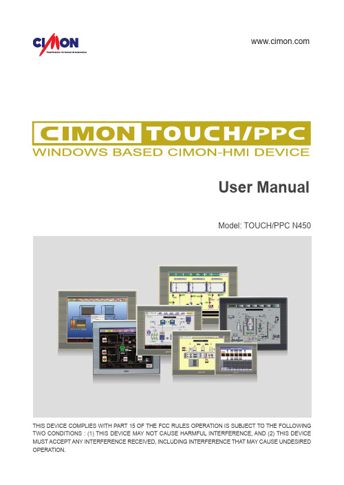
User ManualModel: TOUCH/PPC N450 THIS DEVICE COMPLIES WITH PART 15 OF THE FCC RULES OPERATION IS SUBJECT TO THE FOLLOWING TWO CONDITIONS : (1) THIS DEVICE MAY NOT CAUSE HARMFUL INTERFERENCE, AND (2) THIS DEVICE MUST ACCEPT ANY INTERFERENCE RECEIVED, INCLUDING INTERFERENCE THAT MAY CAUSE UNDESIREDMEMOEssential Safety Precautions030708091317192021242933Essential Safety Precautions EWFPackage Contents Dimensions Interface InstallationWiring & Power Supply Caution Grounding Caution & Specification Calibration Setting Multi-Monitor Setting Products Warranty MEMOCONTENTSPlease do not dissemble or modify the TOUCH/PPC. It will void the Warranty and may cause a high voltage electric shock.This version of the TOUCH/PPC is not rated for flammable environments. Do not use this panel around flammable gases.To prevent an electric shock, confirm that the power supply is turned-off before making any connection to the TOUCH/PPC.Do not use power beyond the specified voltage range of the TOUCH/PPC.Doing so may cause a fire or an electric shock.The TOUCH/PPC uses a lithium battery to back up the internal clock. Do not replace this battery yourself because it may cause an explosion. If the battery needs to be replaced, please contact your local service center.InstallationWiringMaintenanceEssential Safety PrecautionsEWF: Enhanced Write FilterCIMON-TOUCH Installation bookEssential Safety Precautions▪ Installation Guide ▪ CDPackage ContentsCIMON-TOUCH Installation book1. DimensionsDimensionsInterfacesCIMON-TOUCH Installation bookInterfacesCIMON-TOUCH Installation bookCrossover Cable : HostInstallationCIMON-TOUCH Installation book3. Installation3. InstallationWiring and Power Supply CautionCIMON-TOUCH Installation book5. Grounding Caution6. Specification7. Calibration Setting6. Environmental Specifications“PenMount Control Panel” is used to calibrate touch point on the screen.Calibration SettingCIMON-TOUCH Installation book1.Click “PenMount Control Panel”[Start] → [All Programs] → [PenMount Windows Universal Driver] → [Utility] → [PenMount Control Panel]!2.Double click “PenMount 6000 USB”!4.The Red point pops up on the top left corner.Touch the screen with pen and hold for a while to move other point.5.When touching process is done, touch “OK” to save calibration.6.Click [Start] → [EWFman]Keep touching the point as instruction on the screen.3.Click “Standard Calibration” to start calibration.!!Calibration SettingCIMON-TOUCH Installation book7.Click [Commit] → “Yes” to save changed setting.!!If another monitor is used with the TOUCH/PPC, user must set up “Extended Desktop” as following steps.1.Click right button of mouse on the desktop screen.Click “Graphics Options” → “Output To” → “Extended Desktop” → “Monitor+Notebook”*In case of T19FP and P19FP , “Display Properties” must set up as below.Multi-Monitor SettingCIMON-TOUCH Installation book2.Open “PenMount Control Panel”Click “Start” → “PenMount Windows Universal Driver” → “Utility” → “PenMount Control Panel”3.Click [Multiple Monitors] and then click “Multiple Monitor Support” and “Map Touch Screens”4.Click "OK" to move next step.Multi-Monitor SettingCIMON-TOUCH Installation book6.Click "OK" to save setting.7.Click [Start]→[EWFman]5.In this step, touch the screen the screen color changes to white. Press “S” when screen turns to white color.8.Click [Commit] → “Yes” to save changed setting.*Without “Commit”, changed setting value is not saved.Products WarrantyCIMON-TOUCH Installation bookJanuary 2014All Cimon products including hardware, software, and firmware (collectively called “Products”) carry a one-year warranty against defects in materials and workmanship beginning from the date of product receipt from seller or its appointed distributor. If a product proves defective in materials and workmanship within one year from the date of purchase, we will replace or repair it. Products returned under warranty after 30 days may be replaced with refurbished or remanufactured goods at Cimon’s discretion. Cimon makes no representation or warranty, express or implied, that the operation of the Products will be uninterrupted or error free, or that the functions contained therein will meet or satisfy buyer’s intended use or requirements. Repaired or replaced Products provided as a result of this warranty are warranted for a period of six (6) months from the shipment to buyer or the remainder of the original warranty term for that particular product, whichever is longer. Cimon’s standard policy is that all customers are responsible for freight charges to Cimon when returning products under the warranty return policy.This warranty will be void if Products date codes or serial numbers are removed or defaced. Warranties do not apply to products that have been subjected to abnormal use, abnormal conditions, improper storage, exposure to moisture or dampness, unauthorized modifications, unauthorized repair, misuse, neglect, accident, alteration, improper installation or other acts which are not the fault of Cimon, including damage caused in shipping. Our warranty also does not apply to any product that has been damaged by external causes such as fire, flood, sand, dirt, lightning, acts of God, battery leakage, theft, blown fuses, improper use of any electrical source or connection to product not recommended in writing for interconnection by Cimon.8. Multi-Monitor SettingProducts WarrantyIn no event will Cimon be liable, whether in contract, tort or under any other legal theory, for lost profits or revenues, loss of use or similar economic loss, for any indirect, special, incidental, consequential, punitive or similar damages arising out of or in connection with any products including non-conforming products, or for any third party claims against you relating to the products, even if we have been advised of the possibility of such claim. In no event will our monetary liability in respect of any product exceed the purchase price that you paid for it.T o minimize the risk of potential safety problems, you should follow all applicable local and national codes that regulate the installation and operation of your equipment. These codes vary from area to are and usually change with time. It is your responsibility to determine which codes should be followed, and to verify that the equipment, installation and operation is in compliance with the latest revision of these codes. CIMON SOFTWARE AND HARDWARE (COLLECTIVELY REFFERED TO AS, “PRODUCTS”) LICENSE DISCLAIMER AND LIMITATION OFWARRANTIESYOUR USE OF ANY CIMON PRODUCTS AND CONTENT ACCESSIBLE THROUGH THE PRODUCTS IS ENTIRELY AT YOUR OWN RISK. EXCEPT AS DESCRIBED IN THIS AGREEMENT, THE PRODUCTS ARE PROVIDED "AS IS." TO THE MAXIMUM EXTENT PERMITTED BY APPLICABLE LAW, CIMON, ITS AFFILIATES, AND ITS THIRD PARTY SERVICE ORDATA PROVIDERS, LICENSORS, DISTRIBUTORS OR SUPPLIERS (COLLECTIVELY REFERRED TO AS, "SUPPLIERS") DISCLAIM ALL WARRANTIES, EXPRESS OR IMPLIED, INCLUDING ANY WARRANTY THAT THE PRODUCTS ARE FIT FOR A PARTICULAR PURPOSE, TITLE, MERCHANTABILITY, DATA LOSS, NON-INTERFERENCE WITH OR NON-INFRINGEMENT OF ANY INTELLECTUAL PROPERTY RIGHTS, OR THE ACCURACY, RELIABILITY, QUALITY OR CONTENT IN OR LINKED TO THE PRODUCTS. Products WarrantyCIMON-TOUCH Installation book CIMON AND ITS AFFILIATES AND SUPPLIERS DO NOT WARRANTTHAT THE PRODUCTS ARE SECURE, FREE FROM BUGS, VIRUSES,INTERRUPTION, ERRORS, THEFT OR DESTRUCTION. FURTHER,CIMON DOES NOT WARRANT ACCESS TO THE INTERNET OR TO ANYOTHER SERVICE, CONTENT OR DATA TRANSMITTED THROUGH THEPRODUCTS. IF THE EXCLUSIONS FOR IMPLIED WARRANTIES DO NOTAPPLY TO YOU, ANY IMPLIED WARRANTIES ARE LIMITED TO 60 DAYSFROM THE DATE OF PURCHASE OR DELIVERY OF THE PRODUCTS,WHICHEVER IS SOONER.EQUIPMENT DAMAGE OR SERIOUS INJURY TO PERSONNELINCLUDING DEATH CAN RESULT FROM THE FAILURE TO FOLLOW ALLAPPLICABLE CODES AND STANDARDS INCLUDING ENGINEERINGSTANDARDS. CIMON DOES NOT ASSUME ANY RESPONSIBILITY FORYOUR PRODUCT DESIGN, INSTALLATION OR OPERATION.CIMON LTD AND ITS AFFILIATES AND SUPPLIERS DISCLAIM ANYREP-RESENTATIONS OR WARRANTIES THAT YOUR USE OF THEPRODUCTS WILL SATISFY OR ENSURE COMPLIANCE WITH ANYLEGAL OBLIGATIONS OR LAWS OR REGULATIONS.LIMITATION OF LIABILITY AND INDEMNITY. TO THE MAXIMUM EXTENTPERMITTED BY APPLICABLE LAW, THE ENTIRE LIABILITY OF CIMON,AND ITS AFFILIATES AND SUPPLIERS FOR ALL MATTERS OR CLAIMSRELATING TO THIS AGREEMENT SHALL BE LIMITED TO THE AMOUNTYOU PAID FOR THE PRODUCTS DURING THE TWELVE (12) MONTHSPRIOR TO SUCH CLAIM.THE STATUTE OF LIMITATIONS FOR FILING A CLAIM SHALL BE LIMITEDTO THE SHORTER OF TWELVE MONTHS, OR THE SHORTEST PERIODALLOWED UNDER APPLICABLE LAW.Products Warranty Products WarrantyCIMON-TOUCH Installation book Products Warranty MEMOSUBJECT TO APPLICABLE LAW, CIMON AND ITS AFFILIATES ANDSUPPLIERS ARE NOT LIABLE FOR ANY OF THE FOLLOWING: (A) INDIRECT,SPECIAL, INCIDENTAL, PUNITIVE OR CONSEQUENTIAL DAMAGES; (B)DAMAGES RELATING TO FAILURES OF TELECOMMUNICATIONS,THE INTERNET, ELECTRONIC COMMUNICATIONS, CORRUPTION,SECURITY, LOSS OR THEFT OF DATA, VIRUSES, SPYWARE, LOSSOF BUSINESS, REVENUE, PROFITS OR INVESTMENT, OR USE OFSOFTWARE OR HARDWARE THAT DOES NOT MEET CIMON SYSTEMREQUIREMENTS. THE ABOVE LIMITATIONS APPLY EVEN IF CIMONAND ITS AFFILIATES AND SUPPLIERS HAVE BEEN ADVISED OF THEPOSSIBILITY OF SUCH DAMAGES AND/OR THE POSSIBILITY OFDAMAGES GREATER THAN THE LIMITATION ABOVE. THIS AGREEMENTSETS FORTH THE ENTIRE LIABILITY OF CIMON, ITS AFFILIATES ANDYOUR EXCLUSIVE REMEDY WITH RESPECT TO THE SOFTWARE ANDITS USE.THE PARTIES FURTHER AGREE THAT THE APPLICABLE LAW ANDVENUE FOR ANY DISPUTED ARE THE LAWS OF CALIFORNIA. TOTHE EXTENT ALLOWED BY APPLICABLE LAW, ANY CLAIMS SHALL BEBROUGHT IN LOS ANGELES CALIFORNIA AND CALIFORNIA LAW SHALLAPPLY. THE CALIFORNIA VERSION OF THE UCC IS THE PREFERREDLAW TO BE APPLIED TO ANY WARRANT AND RELATED CLAIMS.MEMOCIMON CO.,LTD.H.Q Address :5F KDT B/D, #48, Beolmal-ro, Bundang-gu,Seongnam-si,GyeongGi-do, Korea, 463-836Tel : +82-31-778-3071Homepage : USA :3699 Wilshire Blvd suite 1250 Los Angeles CA90010Tel : 213 384-8703Homepage : BTC18019Version: 1.0。
PPC-1012 SERIES-中英文说明书-C00-2413-025811

免责声明
本公司保留对此手册更改的权利,产品后续相关变更时,恕不另行通知。 对于任何因安装、使用不当而导致的直接、间接、有意或无意的损坏及隐患概不 负责。
订购产品前,请向经销商详细了解产品性能是否符合您的需求。 EVOC 是研祥智能科技股份有限公司的注册商标。本手册所涉及到的其他商 标,其所有权为相应的产品厂家所拥有。 研祥智能科技股份有限公司©2014,版权所有,违者必究。未经许可,不得 以机械、电子或其它任何方式进行复制。
约定 在本文档中,术语“整机”或“产品”有时特指EVOC PPC-1012 SERIES产品。
说明 安全相关注意事项 为避免财产损失以及出于个人安全方面的原因,请注意本入门指南中关于安 全方面的信息。 文中使用警告三角来指示这些安全信息,警告三角的出现 取决于潜在危险的程度。
目录 1.产品介绍 ...................................................................................................................1
其操作必须遵照各自附带的文件说明,特别是其中的安全及警告提示。 由于具 备相关培训及经验,合格人员可以察觉本产品/系统的风险,并避免可能的危险。
EVOC产品 请注意下列说明:
警告 EVOC产品只允许用于目录和相关技术文件中规定的使用情况。如果要使用其他 公司的产品和组件,必须得到EVOC推荐和允许。正确的运输、储存、组装、装 配、安装、调试、操作和维护是产品安全、正常运行的前提。必须保证允许的环 境条件。必须注意相关文件中的提示
特种计算机 Industrial Computer
产品说明书 User Manual
TSCALE PPC 系列计数秤 说明书

PPC 系列计数秤用户手册UGPPC-V1.00PPC 系列计数秤用户手册目录第一章简介 (1)第二章技术规格 (2)2.1 传感器规格 (2)2.2 子秤规格说明 (2)2.3 简要规格 (3)第三章安装 (3)3.1 使用注意事项 (3)3.2 秤的使用 (3)3.2.1 本地秤的安装 (4)3.2.2 远程秤的安装 (4)3.2.3 远程秤的连接 (4)3.2.4 远程秤的设定 (4)3.2.5 打印机的设置 (5)第四章键盘说明 (6)第五章显示 (9)第六章操作 (12)6.1 归零及扣重操作 (13)6.1.1 归零 (13)6.1.2 扣重 (13)6.1.3 远程秤的扣重 (14)6.2 记忆功能 (14)6.2.1 手动累加 (14)6.2.2 自动累加 (15)6.3 计数 (15)6.3.1 通过秤重得出单重 (15)6.3.2 输入已知单重 (16)6.3.3 自动修正单重 (16)6.3.4 检数与检重 (17)6.4 PLU说明 (17)6.4.1 手动存储PLU (17)- i-PPC 系列计数秤用户手册6.4.2 手动存储信息 (18)6.4.3 手动读取PLU信息 (19)6.4.4 清除PLU信息 (20)第七章用户参数 (21)7.1 进入用户参数 (21)7.2 用户参数设定表 (21)7.3 打印注意点 (22)7.4 打印格式 (22)第八章 RS-232输出 (24)8.1 输入命令格式 (24)8.2 通过RS232存储信息 (25)8.3 通过RS-232串口存储PLU信息 (26)第九章标定 (27)第十章错误代码 (29)第十一章技术参数 (30)- ii -PPC 系列计数秤用户手册第一章简介欢迎您使用本公司研制的PPC系列计数秤.本公司PPC系列电子计数秤提供快速,精准的计数功能。
并可外接一远程秤台用于秤重与计数,完成子母秤功能。
轻触按键,具良好触感。
卡乐CPP电子控制器中文手册
+050000765 - 1.2 - 24.03.2009
4
2.3 电气规格
电源(控制器带手操器) 绝缘等级 端子排 内置电池的时钟
中文
230 Vac, +10...-15% 适用于CPPA******; 24 Vac +10 to -15% 50/60 Hz, 28 to 36 Vdc +10 to -20% 适用于CPPB****** 最大输入功率: 25 VA 双重绝缘
• 插拔式公制/阴制接头,最大电压 250 Vac;
线缆横截面积: 最小 0.5 mm2 - 最大 2.5 mm2
• 快速接头 • 固定螺接头
仅适用于 CPP****B**/CPP****D** 表. 2.a
2.4 开关量输入
型号: 电压-无源触点
主板类型 小型 中型
数量 7 10
注意:将传感器和开关量输入信号线与带电感负载的线缆和 电源线尽量分离,以避免电磁干扰。
2.5 模拟量输出
类型 最大数量 分辨率 最大负载 精确度
0 to 10 Vdc 小型和中型的主板分别为3个和4个 8位 2 kΩ (5 mA) 满量程±0.3 % 满量程±5 %, 最大负载(5 mA)
表. 2.b
5
+050000765 - 1.2 - 24.03.2009
中文
2.6 模拟量输入
模拟量转换 最大数量 type B1, B2, B3, B4, B8, B9
B5, B10
B6, B7, B11, B12
输入的时间常数 输入的精度 测量回路的分类 (CEI EN 61010-1)
10 位模/数转换 小型的7个,中型的12个 低温NTC型:在25°C时为10 kΩ,± 0.1%,-50~90 °C; 高温NTC型:在25°C时为50 kΩ,0~150 °C; 0~1 Vdc输入; 低温NTC型:在25°C时为10 kΩ, -50~90 °C; 高温NTC型:在25°C时为50 kΩ,0~150 °C; 0~1 Vdc输入; 4~20 mA输入; 低温NTC型:在25°C时为10 kΩ, -50~90 °C; 高温NTC型:在25°C时为50 kΩ,0~150 °C; 0~1 Vdc输入 公制比例式压力传感器(0~5 V) 0.5 秒 满量程±0.3 % I类
PPC入门

PPC入门一.PPC使用基础篇之开机引导设置步骤对于第一次购买到手的机器,开机后必须对它进行简单的设置后才能开始使用。
这个设置步骤微软是采取引导的方式来提示你进行……点击“NEXT”按钮后屏幕的变化:它提示你需要用笔点并按住屏幕中的长条形位置。
点按住后,屏幕中会弹出个小的对话框。
此时,请你松开触笔,并点选其中红色的“CUT”菜单,再放开触笔!之后,屏幕跳转到该页面。
请用触笔在显示的11点位置点按住屏幕!此时,又会弹出个小的对话框,请点选红色的“PASTE”菜单!你仔细看屏幕,刚才被剪切的部分已经被粘贴到了11点的位置,而且告诉你PPC弹出菜单的设置成功!其实我们上面操作的“CUT”和“PASTE”就是我们知道的“剪切”与“粘贴”功能!以后设计到PPC操作的“剪切”与“粘贴”操作,都是这样完成!(相当于台机的鼠标右键功能)以上是针对PPC弹出菜单的设置。
二.简单上手PPC软件教程一,软件安装常见有三种安装方法,我们从目前应用最多的绿色程序的使用讲起。
第一种:绿色安装法这种安装软件方法是最为简单的,直接把以.exe结尾的文件直接拷贝到ppc中,然后直接点击运行。
那么如何分辨哪种是直接安装哪种是绿色安装程序呢?一般情况是这样的,我们在台式机上看到的ppc软件如果是可执行文件.exe结尾的,就直接用鼠标点击它,如果是WM智能手机上的绿色程序文件,它会跳出一个窗口告诉你:这不是一个有效的Win32程序。
第二种:直接安装法就像我们给电脑安装软件一样,软件的文件夹或者单独文件都会出现setup.exe或者install.exe后缀的可执行文件,我们直接双击就可以。
按照系统一步步地提示,台式机内装载的activesync会自动弹出一个窗口,里面会出现选项,让你来选择程序安装的位置:内存或者卡里,通常安装在卡里比较好,因为现在卡的容量是比较大,而内存的容量有限。
第三种:.cab文件安装法这类程序不是以可执行文件形式存在的,而是以压缩形式存在,但是后缀名不是.zip 或者.rar而是.cab,凡是以.cab为后缀的压缩文件就可以将其直接考到掌上电脑中,在掌上电脑上直接运行就可以完成安装。
ATCS PPC11系列PLC 硬件说明书

PPC11系列可编程控制器使用手册V1.2德维森科技(深圳)有限公司地址:深圳市南山区高新区科技南12路中电照明中心北二楼邮编:518057电话:*************,*************传真:*************网址:目 录前 言 (3)第一章 PPC11系列PLC的特性与规格 (4)1.1概述 (4)1.2PPC11系列可编程控制器硬件组成 (5)1.3特性与规格 (5)1.3.1PPC11系列PLC的特性 (5)1.3.2PPC11系列的系统规格表 (6)第二章 PPC11系列CPU模块 (7)2.1简介 (7)2.2CPU模块外部介绍 (9)2.2.1CPU动作状态LED显示: (9)2.2.2CPU动作开关 (10)2.2.3COM #1接口接线图 (14)2.2.4COM #2接口接线图 (15)第三章系统架构 (16)3.1底板 (16)3.2扩展I/O底板 (17)3.3扩展电缆 (18)3.4电源 (18)3.4.1电源(PWS10/PWS50) (18)3.4.2 电源指示灯: (18)3.4.3 电源接线端子: (18)3.4.4 规格 (18)3.4.5 面板及接线 (19)3.4.6 电源消耗 (19)3.5I/O架构 (21)3.6I/O MAP (22)3.7远程I/O模块 (24)3.7.1一般规格 (24)3.7.2主要任务 (24)3.7.3外部介绍 (24)3.7.4地址设定 (26)第四章 PPC11系列PLC的设置与安装 (29)4.1硬件要求 (29)4.2考虑事项 (29)4.3其他注意事项 (29)4.4安装步骤 (30)4.5电气和环境参数 (30)4.6系统安装与连接 (31)第五章开关量模块 (32)5.116点,12/24V DC输入模块(IDD40) (32)5.232点,12/24V DC输入模块(IDD50) (34)5.316点,110V AC输入模块(IDA40) (36)5.416点,220V AC输入模块(IDA41) (38)5.516点,DC0.1A输出模块(ODD40) (40)5.616点,DC2A PNP输出模块(ODD42) (42)5.716点,继电器输出模块(ODA40) (44)第六章模拟量模块 (46)6.1.模拟量输入模块(IAD24/IAD25/IAD26/IAD27) (46)6.1.1. 概述 (46)6.1.2. 规格 (46)6.1.3. 结构 (46)6.2.模拟量输入模块(IAD30/IAD31) (52)6.2.1. 概述 (52)6.2.2. 规格 (52)6.2.3. 结构 (52)6.3.模拟量输出模块(OAD20) (58)6.3.1. 概述 (58)6.3.2. 规格 (58)6.3.3. 结构 (58)6.4.模拟量输入/输出模块(AAD20/AAD21/AAD22/AAD23) (62)6.4.1. 概述 (62)6.4.2. 规格 (62)6.4.3. 结构 (62)6.5.热电阻模块(RTD10) (68)6.5.1. 概述 (68)6.5.2. 规格 (68)6.5.3. 结构 (68)6.6.热电偶模块(THM10) (73)6.6.1. 概述 (73)6.6.2. 规格 (73)6.6.3. 结构 (73)第七章高速计数模块 (HSC10) (79)7.1.概述 (79)7.2.规格 (79)7.3.结构 (79)7.3.1. 概述 (79)7.3.2 系统结构 (84)前 言PPC11可编程控制器的主要动作是:控制器读取连接于输入模块上不同输入装置(如各种开关与传感器)的信号,执行储存于内存的梯形图程序,并将结果送至输出模块的输出装置(如电磁阀、马达等)。
PPC新手入门教程

【转】PPC新手入门教程PPC新手入门教程有好多朋友是第一次用Windows Mobile系统的手机,对其相关操作可能不是很熟悉,特从各大网站搜罗的一些新手教程,供大家参考。
一、关于目录名许多英文软件都是不支持中文名目录的,尤其是大型软件,比如游戏。
而游戏又应该装在卡里面,所以卡名是英文名,很重要。
打开注册表HKEY_LOCAL_MACHINE\\System\\StorageManger\\Profiles,从里面的文件夹找一找有没有Floder值为你的卡名的,如果有,要把它改为英文名,比如我的“存储卡”就可以改为“CF Card”,可以根据喜好来定。
二、关于主人名称现在有些软件的注册机还不够完善,不能够通过中文的主人名称进行算号,所以你的主人名称一定要是英文的,以便于软件的注册。
[该操作可能会让软件重新注册]三、关于重启PPC有两种重起模式:软重起和硬重起。
软重起相当于电脑上的重起,数据并不会丢失,而硬重起相当于电脑上格式化硬盘+重装系统,硬重起相当于掉电,使RAM内数据丢失,恢复到出厂状态。
硬起不会让ROM内的数据丢失,所以把文件装在ROM里面就不用怕丢失了。
四、关于备份用PPC要有备份的习惯,万一有一天硬起或者系统不稳定,可以随时恢复备份,这个时候就显出了备份的用处。
硬起后,所有软件和文档丢失,光安装软件就需要近一个小时,不但费时还费力。
如果备份后,几分钟就可以恢复系统,接下来只要校对时间就可以了。
一般要经常备份,比如说一个星期备份一次是比较合理的,使得文件和备份有一定的同步性。
硬起之后刚装上软件也要备份,待系统不稳定时,硬起一下然后恢复系统,就能回到比较清净的环境中。
有人说,备份就不怕硬起了。
也有不怕系统混乱的特点。
时常备份,做到有备无患就可以了!五、内存清理1.程序内存清理[本操作建议任何时间操作]有的时候,某些程序退出时不会清理内存,使得程序内存空间还在占用,让本来宝贵的空间变得更小。
CAREL pCOxs 说明书

1
pCOxs manual -cod.+030220345-rel.1.0-18.03.03
目录
简介 1. 总体特性..................................................................................... 4
1.1 pCOxs..................................................................................... 4 1.2 程序..................................................................................... 4 2. 硬件结构..................................................................................... 5 2.1 设备和附件代码............................................................................ 7 2.2 输入/输出说明............................................................................. 9 3. 用户手操作器................................................................................. 10 3.1 LCD显示屏对比度的调节..................................................................... 10 3.2 墙壁安装或面板安装4×20LCD显示屏.......................................................... 10 3.3 墙壁安装或面板安装LED显示屏............................................................... 10 3.4 墙壁安装或面板安装LCD图形显示屏........................................................... 10 3.5 面板安装4×20LCD显示屏.................................................................... 11 3.6 面板安装LCD图形显示屏..................................................................... 11 3.7 3个数码LED显示,32×72..................................................................... 11 3.8 pCO手操器的按键........................................................................... 11 3.9 图形显示屏字符的特性和功能................................................................ 12 4. 安装................................ 14 4.1 pCOxs的安装固定........................................................................... 14 4.2 所用电源.................................................................................. 14 4.3 安装条件.................................................................................. 14 4.4 模拟量输入连接............................................................................ 15 4.5 开关量输出连接............................................................................ 17 4.6 0/10V模拟量输出连接....................................................................... 17 4.7 PWM模拟量输出连接......................................................................... 17 4.8 开关输出连接.............................................................................. 18 4.9 用户手操器的安装.......................................................................... 18 4.10 安装用于图形显示手操器的程序存储器EPROM.................................................. 19 5. pLAN局域网................................................................................... 20 5.1 设置pCO1地址.............................................................................. 21 5.2 设置手操器地址............................................................................ 21 5.3 专用和共用手操器.......................................................................... 21 5.4 pLAN电气连接.............................................................................. 22 5.5 在pLAN局域网中远距离安装手操器............................................................ 24 5.6 plAN局域网的技术说明...................................................................... 26 6. MP 总线网.................................................................................... 26 7. 可选卡....................................................................................... 27 7.1 用于维护和监视用的RS485串行卡............................................................. 27 7.2 用于是Modem管理的RS232串行卡.............................................................. 27 7.3 时钟卡.................................................................................... 28 7.4 用于4×20LCD显示屏或6个LED显示屏的串行打印卡.............................................. 28 7.5 用于图形显示器的串行打印卡,PCOSERPRN0..................................................... 28
工控机 PPC-L157T
1.2.2 标准 PC 功能 ..............................................2
1.2.3 VGA/LCD 接口 .............................................3
1.2.4 音频功能 .................................................3
图 2.1: PPC-L157T 前视图 ...............................8
图 2.2: PPC-L157T 后视图 ...............................8
图 2.3: PPC-L157T 侧视图 ...............................9
2.3
运行 BIOS 安装程序..............................................10
2.4
安装系统软件...................................................11
2.4.1 方式 1:使用以太网 ......................................11
注意! 如果电池放置不正确,将有爆炸的危险。 因此,只可以使用制造商推荐的同一种或者同等型号的电池进行替换。
警告! 1. 输入电压范围为 12-24 V,6-3.75A。 2. 使用 3 V @ 195 mA 锂电池。 3. 包装:需特别谨慎,请以双手托住设备。 4. 维护:正确进行表面维护与清洁,只可使用认可的产品或以干燥的 物品进行清洁。 5. CompactFlash:插入或移动 CompactFlash 存储卡之前,请关闭电 源。