SEIKO 霍尔IC S-57M1 Series 规格书_1
步进电机选型手册
北京飞凌东泰电子技术有限公司
010-69732383
86 圆形步进电机系列
技术数据:
步进电机型号
步距 角 (°)
静力 矩 (N.m)
电流 (A)
电阻 (Ω)
电感 (mH)
引线 数 (NO.)
机身 长 (mm)
转动 惯量
重量 (Kg)
(g.cm^2)
FL86BYG62
1.8 1.8 1.9 2.6 9.7
长度 (mm)
115
150
转动 (g.cm^2)
5500 11000
重量 (Kg)
5 8.4
电机轴径均为 19mm,键槽尺寸为 6*35mm 接线图:
北京飞凌东泰电子技术有限公司
010-69732383
130 圆形步进电机系列
技术数据:
步距角
型号
(°)
静力矩 (N.m)
电流 (A)
电阻 (Ω)
电感 (mH)
外形图:
相感抗(mH ±20%)
2.3 25 4.2 36 6
长度 (mm)
71 103 103 135 135
重量 (Kg)
1.7 2.85 2.85
4 4
型号 FL86BYG3A71 FL86BYG3A103 FL86BYG3A103 FL86BYG3A135 FL86BYG3A135 接线图:
型号
FL86BYG65
FL86BYG80 FL86BYG118 FL86BYG156
轴径 键槽
φ9.5 、 单平台
φ14
0.8×25
φ12.7 25
φ15.875 5×25
北京飞凌东泰电子技术有限公司
接线图:
铁磁器产品说明书

Dimensions: [mm]Scale - 7:1Product Marking:Marking4R7 (Inductance Code)7440404104774404041047BC74404041047T e m p e r a t u r eT pT L74404041047Cautions and Warnings:The following conditions apply to all goods within the product series of WE-LQS of Würth Elektronik eiSos GmbH & Co. KG:General:•This electronic component is designed and manufactured for use in general electronic equipment.•Würth Elektronik must be asked for written approval (following the PPAP procedure) before incorporating the components into any equipment in fields such as military, aerospace, aviation, nuclear control, submarine, transportation (automotive control, train control, ship control), transportation signal, disaster prevention, medical, public information network etc. where higher safety and reliability are especially required and/or if there is the possibility of direct damage or human injury.•Electronic components that will be used in safety-critical or high-reliability applications, should be pre-evaluated by the customer. •The component is designed and manufactured to be used within the datasheet specified values. If the usage and operation conditions specified in the datasheet are not met, the wire insulation may be damaged or dissolved.•Do not drop or impact the components, the component may be damaged.•Würth Elektronik products are qualified according to international standards, which are listed in each product reliability report. Würth Elektronik does not warrant any customer qualified product characteristics beyond Würth Elektroniks’ specifications, for its validity and sustainability over time.•The responsibility for the applicability of the customer specific products and use in a particular customer design is always within the authority of the customer. All technical specifications for standard products also apply to customer specific products.Product specific:Soldering:•The solder profile must comply with the technical product specifications. All other profiles will void the warranty.•All other soldering methods are at the customers’ own risk.•Strong forces which may affect the coplanarity of the components’ electrical connection with the PCB (i.e. pins), can damage the part, resulting in avoid of the warranty.Cleaning and Washing:•Washing agents used during the production to clean the customer application might damage or change the characteristics of the wire insulation, marking or plating. Washing agents may have a negative effect on the long-term functionality of the product.•Using a brush during the cleaning process may break the wire due to its small diameter. Therefore, we do not recommend using a brush during the PCB cleaning process.Potting:•If the product is potted in the customer application, the potting material may shrink or expand during and after hardening. Shrinking could lead to an incomplete seal, allowing contaminants into the core. Expansion could damage the components. We recommend a manual inspection after potting to avoid these effects.Storage Conditions:• A storage of Würth Elektronik products for longer than 12 months is not recommended. Within other effects, the terminals may suffer degradation, resulting in bad solderability. Therefore, all products shall be used within the period of 12 months based on the day of shipment.•Do not expose the components to direct sunlight.•The storage conditions in the original packaging are defined according to DIN EN 61760-2.•The storage conditions stated in the original packaging apply to the storage time and not to the transportation time of the components. Packaging:•The packaging specifications apply only to purchase orders comprising whole packaging units. If the ordered quantity exceeds or is lower than the specified packaging unit, packaging in accordance with the packaging specifications cannot be ensured. Handling:•Violation of the technical product specifications such as exceeding the nominal rated current will void the warranty.•Applying currents with audio-frequency signals may result in audible noise due to the magnetostrictive material properties.•The temperature rise of the component must be taken into consideration. The operating temperature is comprised of ambient temperature and temperature rise of the component.The operating temperature of the component shall not exceed the maximum temperature specified.These cautions and warnings comply with the state of the scientific and technical knowledge and are believed to be accurate and reliable.However, no responsibility is assumed for inaccuracies or incompleteness.Würth Elektronik eiSos GmbH & Co. KGEMC & Inductive SolutionsMax-Eyth-Str. 174638 WaldenburgGermanyCHECKED REVISION DATE (YYYY-MM-DD)GENERAL TOLERANCE PROJECTIONMETHODChriB002.0012023-02-28DIN ISO 2768-1mDESCRIPTIONWE-LQS SMT Semi-ShieldedPower Inductor ORDER CODE74404041047SIZE/TYPE BUSINESS UNIT STATUS PAGEImportant NotesThe following conditions apply to all goods within the product range of Würth Elektronik eiSos GmbH & Co. KG:1. General Customer ResponsibilitySome goods within the product range of Würth Elektronik eiSos GmbH & Co. KG contain statements regarding general suitability for certain application areas. These statements about suitability are based on our knowledge and experience of typical requirements concerning the areas, serve as general guidance and cannot be estimated as binding statements about the suitability for a customer application. The responsibility for the applicability and use in a particular customer design is always solely within the authority of the customer. Due to this fact it is up to the customer to evaluate, where appropriate to investigate and decide whether the device with the specific product characteristics described in the product specification is valid and suitable for the respective customer application or not.2. Customer Responsibility related to Specific, in particular Safety-Relevant ApplicationsIt has to be clearly pointed out that the possibility of a malfunction of electronic components or failure before the end of the usual lifetime cannot be completely eliminated in the current state of the art, even if the products are operated within the range of the specifications.In certain customer applications requiring a very high level of safety and especially in customer applications in which the malfunction or failure of an electronic component could endanger human life or health it must be ensured by most advanced technological aid of suitable design of the customer application that no injury or damage is caused to third parties in the event of malfunction or failure of an electronic component. Therefore, customer is cautioned to verify that data sheets are current before placing orders. The current data sheets can be downloaded at .3. Best Care and AttentionAny product-specific notes, cautions and warnings must be strictly observed. Any disregard will result in the loss of warranty.4. Customer Support for Product SpecificationsSome products within the product range may contain substances which are subject to restrictions in certain jurisdictions in order to serve specific technical requirements. Necessary information is available on request. In this case the field sales engineer or the internal sales person in charge should be contacted who will be happy to support in this matter.5. Product R&DDue to constant product improvement product specifications may change from time to time. As a standard reporting procedure of the Product Change Notification (PCN) according to the JEDEC-Standard inform about minor and major changes. In case of further queries regarding the PCN, the field sales engineer or the internal sales person in charge should be contacted. The basic responsibility of the customer as per Section 1 and 2 remains unaffected.6. Product Life CycleDue to technical progress and economical evaluation we also reserve the right to discontinue production and delivery of products. As a standard reporting procedure of the Product Termination Notification (PTN) according to the JEDEC-Standard we will inform at an early stage about inevitable product discontinuance. According to this we cannot guarantee that all products within our product range will always be available. Therefore it needs to be verified with the field sales engineer or the internal sales person in charge about the current product availability expectancy before or when the product for application design-in disposal is considered. The approach named above does not apply in the case of individual agreements deviating from the foregoing for customer-specific products.7. Property RightsAll the rights for contractual products produced by Würth Elektronik eiSos GmbH & Co. KG on the basis of ideas, development contracts as well as models or templates that are subject to copyright, patent or commercial protection supplied to the customer will remain with Würth Elektronik eiSos GmbH & Co. KG. Würth Elektronik eiSos GmbH & Co. KG does not warrant or represent that any license, either expressed or implied, is granted under any patent right, copyright, mask work right, or other intellectual property right relating to any combination, application, or process in which Würth Elektronik eiSos GmbH & Co. KG components or services are used.8. General Terms and ConditionsUnless otherwise agreed in individual contracts, all orders are subject to the current version of the “General Terms and Conditions of Würth Elektronik eiSos Group”, last version available at .Würth Elektronik eiSos GmbH & Co. KGEMC & Inductive SolutionsMax-Eyth-Str. 174638 WaldenburgGermanyCHECKED REVISION DATE (YYYY-MM-DD)GENERAL TOLERANCE PROJECTIONMETHODChriB002.0012023-02-28DIN ISO 2768-1mDESCRIPTIONWE-LQS SMT Semi-ShieldedPower Inductor ORDER CODE74404041047SIZE/TYPE BUSINESS UNIT STATUS PAGE。
克罗韦尔 MagneMotion QuickStick HT 1 米电机 数据表

•QuickStick High Thrust systems consist of modules that include motors mounted to user-designed support structures, magnet arrays mounted to user-designed vehicles, motor controllers, system controllers, and power supplies.•All QSHT motors contain integral position sensing and use external QuickStick High Thrust Motor Controllers.•Mounting holes are located on the motor bottom for mounting.•Motor is designed for IP67 (IEC 60529), motor controller is designed for IP20 and can be located remotely.•CE Certified, UL Recognized.Physical SpecificationsEnvironmental Specifications*All dimensions are millimeters. Contact MagneMotion for detailed drawings.Electrical SpecificationsPerformance Specifications ‡†The drive current to the stator is controlled by the QSHT controller and is thermally limited.‡Operating performance will vary based on payloads, acceleration and velocity settings, and vehicle density.§Maximum Acceleration and Velocity are at recommended maximum payload.¶Thrust at Nominal Vehicle Gap (distance between the magnet array and the motor) of 12mm, per magnet array cycle.◊Repeatability is dependent on the size of the gap between the motor and the vehicle and may vary based on track and vehicle design/structure.Repeatability is not applicable over the gaps between motors.Dimensions *:104.0 W x 73.0 H x 966.4 L Ambient Temperature:0 °C to 50 °C at rated power0 °C to 85 °C with power derating Weight:37.6kg [83.0lbs]Relative Humidity:N/APower Rating, Max †:10A RMS continuous,14A RMS overload (2sec max) @ 400V maxAcceleration, Max §:60m/s 2 [6.1g] payload dependent Velocity, Max §: 3.5m/s [7.8mph]Thrust, Max ¶:25% duty cycle – 190N/cycle 100% duty cycle – 99N/cycle Servo Repeatability ◊:±1mm [0.04in] nominalRecommended Maximum Payload:4,500kg [9900lb] per vehicle(determined by magnet array length and support structure)73.0 ±0.718104 ±1QuickStick HT 1m MotorRockwell Automation SupportUse the following resources to access support information.Documentation FeedbackY our comments will help us serve your documentation needs better. If you have any suggestions on how to improve this document, complete the How Are W e Doing? form at /idc/groups/literature/documents/du/ra-du002_-en-e.pdf .Technical Support CenterKnowledgebase Articles, How-to Videos, FAQs, Chat, User Forums, and Product Notification Updates.https:///Local Technical Support Phone Numbers Locate the phone number for your country./global/support/get-support-now.page Direct Dial Codes Find the Direct Dial Code for your product. Use the code to route your call directly to a technical support engineer./global/support/direct-dial.page Literature LibraryInstallation Instructions, Manuals, Brochures, and Technical Data./global/literature-library/overview.page Product Compatibility and Download Center (PCDC)Get help determining how products interact, check features and capabilities, and find associated firmware./global/support/pcdc.pageRockwell Otomasyon Ticaret A.Ş., Kar Plaza İş Merkezi E Blok Kat:6 34752 İçerenköy, İstanbul, T el: +90 (216) 5698400Rockwell Automation maintains current product environmental information is on its website at /rockwellautomation/about-us/sustainability-ethics/product-environmental-compliance.page .Product certificates are located in the Rockwell Automation Literature Library: /global/literature-library/overview.page Allen-Bradley, Rockwell Software, and Rockwell Automation are trademarks of Rockwell Automation, Inc.Trademarks not belonging to Rockwell Automation are property of their respective companies.Copyright © 2017 MagneMotion, A Rockwell Automation Company. All Rights Reserved.139 Barnum Road, Devens, MA 01434, USA +1 978-757-9100Publication MMI-TD024A-EN-P - February 2017DIR 990000679。
派克液压密封件说明书

派克汉尼汾公司版权所有未经许可不能摘录,翻印。
保留修改权利2021年6月警告销售条件本样本中产品和/或系统或相关产品出现故障,选型不当或使用不当,均可能导致人身伤亡和财产损失。
本文档以及由派克·汉尼汾公司及其子公司和授权经销商提供的其他资料,为具有技术知识的用户提供进一步研究所需的产品和/或系统选项。
重要的是,用户必须对您的应用进行全面的分析,并对当前产品样本中与产品或系统相关的资料进行评估。
由于工作条件以及产品或系统的多样性,用户必须自行分析和测试,并独自承担一切后果,包括:产品和系统的最终选型以及确保满足应用的所有性能、安全和警告等方面的要求。
派克·汉尼汾及其子公司可能会随时对本样本中的产品,包括但不限于:产品的特性、产品的规格、产品的结构、产品的有效性以及产品的价格作出变更而不另行通知.本样本中的所有产品均由派克·汉尼汾公司及其子公司和援权经销商销售。
与派克签订的任何销售合同均按照派克标准条件和销售条件中规定的条款执行(提供复印件备索)。
本公司的密封件,只能在本公司的文件资料述及的应用参数范围与接触介质、压力、温度和存放时间相一致的情况下才能使用。
在规定的应用参数范围外使用以及错误选用不同的材料都可能导致密封件寿命的缩短以及设备的损坏,甚至更严重的后果(如生命安全,环境污染等)。
样本中所列出的工作压力、温度范围、运动速度是极限值,它们之间相互关联、相互影响;在极端的工况下,建议不要同时把各个参数都同时用到极限值。
对于特殊的要求(压力、温度、速度、介质等),请联系派克汉尼汾公司以咨询合适的密封结构、材料、配置、安装建议等。
由于诸多工作参数会影响到流体传动系统及密封元件,这些设备的制造商必须在实际工作条件下测试、验证并批准密封系统的功能与可靠性。
此外,对于不断出现的新的介质(液压油、润滑脂、清洗剂等),用户特别注意它们与目前所用的密封件弹性体材料的兼容性。
我们建议用户在大批量应用之前,在厂内或现场先做密封材料的兼容性能测试,作为密封产品与系统供应商,我们建议用户遵循我们的这些建议。
PROTEM57操作手册
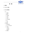
目录A).初始配置B).TEM57-MK2发射机C).PROTEM数字接收机1、介绍1.1 接收器盖1.1.1 键的功能1.2 内部仪表盘1.3 内部开关1.4 启动菜单1.4.1 显示对比度调节1.4.2 复位1.5 主菜单2、设定测量参数2.1 初始计算机设定2.2 前ADJUST(调节)子菜单2.2.1 同步模式A)参考同步B)晶体同步2.2.2 重复频率2.2.3 线圈类型2.2.4 增益选择2.2.5 噪音显示和增益设定2.2.6 积分时间2.2.7 Rx延迟时间2.2.8 接通时间测量2.2.9 线圈面积2.2.10 校准时间常数和检查2.3 TEST(测试)子菜单2.3.1 电池和程序版本2.3.2 自动校准2.3.3 校准检查2.3.4 系统测试2.3.5 晶振漂移2.3.6 重新同步2.4 HEADER(带头)子菜单2.5 STATION(测量站)子菜单2.6 COMPONENT(分量)子菜单2.7 SCOPE(示波器)功能3、获取和浏览数据3.1 测量3.1.1 图形显示3.2 RECALL(回叫)子菜单3.2.1 图形显示3.2.2 表格显示3.3 PROFILE(剖面)子菜单4、测量数据管理4.1 FILE(文件)目录4.2 转贮数据至主机5、现场故障处理5.1 常规检查步骤5.2 电源故障5.3 无显示5.4 校准故障5.5 灯闪烁/显示闪烁5.6 计算机失灵5.7 内存故障6、门位置6.1 20门模式6.2 30门模式D).电池充电1、接收机电屏2、接收机外接电屏3、发射机电屏4、电屏维护E).采集勘测数据1、信噪比和勘测效率2、调整接收机的增益3、增益设置和求平均值4、选择重复频率5、调整每个分量的记录6、标定检测7、系统极性F). 电源线的干扰G). 发射线框H). 勘测极性的惯例I). PROTEM接收机线圈的有效面积J). 系统方框图K). 技术指标PROTEM57-MK2D(C)操作手册A). 初始配置在勘测开始时,需选择发射线框的尺寸,同步方式(参见C. 2.2.1节)和重复频率。
两极单极检测型霍尔IC设计指南(中文)
Rev.2.7_00两极/单极检测型S-5711A系列霍尔ICS-5711A系列是采用CMOS技术开发的高灵敏度、低消耗电流的霍尔IC(磁性开关IC)。
可检测出磁束密度的强弱,使输出电压发生变化。
通过与磁石的组合,可进行各种设备的开/关检测。
由于采用了超小型的SNT-4A或SOT-23-3封装,因此可高密度安装。
同时,由于消耗电流低,因此最适用于便携设备。
特点•内置斩波放大器•可选范围广,支持各种应用极性检测:检测两极、检测S极、检测N极磁性检测逻辑:动态“L”、动态“H”输出方式: Nch开路漏极输出、CMOS输出•宽电源电压范围: 2.4 V ~ 5.5 VµA 典型值、8.0 µA 最大值•低消耗电流: 5.0•工作温度范围:-40°C ~ +85°C磁性的温度依赖性较小SOT-23-3•采用小型封装: SNT-4A,•无铅产品用途•手机(翻盖式、滑盖式等)•膝上型电脑•数码摄像机•玩具、游戏机•家用电器产品封装图面号码封装名封装图面卷带图面带卷图面焊盘图面SNT-4A PF004-A PF004-A PF004-A PF004-A-MP003-ZMP003-CSOT-23-3 MP003-C两极/单极检测型霍尔ICS-5711A系列Rev.2.7_00 框图1.Nch开路漏极输出产品OUTVSS*1.寄生二极管图12.CMOS输出产品OUTVSS*1.寄生二极管图2两极/单极检测型霍尔IC Rev.2.7_00S-5711A系列 产品型号的构成1.产品名(1) SNT-4AS-5711 A x x x – I4T1 G封装简称和IC的包装规格*1I4T1 :SNT-4A、卷带产品磁性检测逻辑L :动态“L”H :动态“H”极性检测D :检测两极S :检测S极N :检测N极输出方式N :Nch开路漏极输出C :CMOS输出*1.请参阅卷带图。
(2) SOT-23-3S-5711 A x x x x – M3T1S封装简称和IC的包装规格*1M3T1 :SOT-23-3、卷带产品磁性灵敏度无:B OP = 3.8 mT典型值1 :B OP = 5.0 mT典型值磁性检测逻辑L :动态“L”H :动态“H”极性检测D :检测两极S :检测S极N :检测N极输出方式N :Nch开路漏极输出C :CMOS输出*1.请参阅卷带图。
HIOKI儀器產品選購指南说明书
Ⴍ 高速20通道/變壓器L/C/Z/DCR/圈數/短路/平衡掃描測試功能 高速80通道/變壓器L/C/Z/DCR/圈數/短路/平衡掃描測試功能
20通道/變壓器L/C/Z/DCR/圈數/短路/平衡掃描測試功能 3250加LCR錶分析功能 3252 1MHz版
3302加通訊參數測量功能
ٜࠠݴᛌཥݴ๕ / ༊ӻ୕፯ᒅܸی
Ꮠ͜Ⴍ LCD Inverter變壓器(陶瓷電容、線材、PCB)
耐久性測試/耐壓測試/崩潰電壓測試 外部電極螢光燈管(EEFL),背光耐久性/燈管電流測試 交換式電源供應器(SMPS)主變壓器與主動式功率因素修正器
(Active PFC) Choke耐久性測試與電氣特性分析 醫療設備高頻漏電流安規檢驗
ࠫϣ 12-34 12-34 12-34 12-34 12-35 12-35
0.1mΩ ~ 100MΩ 0.1mΩ ~ 100MΩ 0.1mΩ ~ 100MΩ 0.01mΩ ~ 100MΩ 0.01mΩ ~ 100MΩ
3252
20Hz~200kHz
0.1mΩ ~ 100MΩ
3302
20Hz~1MHz
0.1mΩ ~ 100MΩ
Ⴍ 電容量高速檢測 全數位分類,比較器功能,可選無10kHz版 全數位分類,比較器功能
提供高頻高壓交流與直流電源供應的功能,供平面螢光燈(FFL) 與表面傳導電子發射顯示器(SED)裝置分析使用
直流/直流轉換器SMD Power Choke溫昇測試 (直流重疊電流與交流漣波電壓)與電氣特性分析
緩衝電容壽命測試 高壓電容壽命測試 LCD Inverter變壓器(陶瓷電容、線材、PCB)生產線耐壓測試 醫療設備高頻漏電流安規檢驗 車用驅動馬達生產線電暈(Corona)放電檢驗 被動元件(換流器變壓器、陶瓷電容、高壓線材、PCB等) 高頻高壓壽命測試
SEIKO 手表 5R65 5R66 商品说明书
6我们真诚地感谢您购买 SEIKO 手表。
为了保证您正确地使用好您的 SEIKO 手表,请您在使用之前认真阅读说明书。
请妥善保管好说明书,以便在需要的时候可以随时拿出来阅览。
*关于金属表带的调整,可以联系购买该产品的商店为您做调整。
如果因礼品赠送或者搬家等而无法联系购买商店为您做调整,可以与 SEIKO 客户服务中心取得联系。
如果在非购买商店调整,有时可能会收取费用或者不能为您提供相关服务。
*商品上有时会贴有一层防止损伤用的保护膜。
务必要把保护膜揭下来以后再使用。
如果在贴有保护膜状态下使用,则会因沾上污渍、汗水、尘埃、水分等而导致生锈。
1使用注意事项 (4)特性 (8)各部分的名称及其功能 (10)表冠 (12)如何给主发条上弦 (13)关于主发条上弦状态的说明 (13)如何使用表冠给主发条上弦(手动上弦) (14)动力储存指示器 (15)如何查看动力储存指示器 (16)1如何设置时间和日期 (17)如何设置时间和日期 (17)有关如何更精确设置时间的提示 (20)月末日期调整 ........................211如何设置时间和日期 (22)如何设置时间和日期 (22)有关如何更精确设置时间的提示 (25)月末日期调整 (26)如何使用 24 小时指针 (29)2时差调整功能 (31)如何使用时差调整功能 (31)世界主要地区的时区差异表 (33)3 如何使用简易指南针(对于带有旋转表圈和方向指示符的型号) (35)如何使用 24 小时指针来确定方向 (35)4 如何使用带有 24 小时刻度的旋转表圈(对于带有旋转表圈和 24 小时刻度的型号) (37)当 24 小时指针被设为 24 小时制的时针和分针时 (37)当 24 小时指针被设为不同时区时 (39)SC2日常保养 (40)功能和型号 (41)Lumibrite(智慧光能) (42)防水功能 (43)抗磁功能 (44)表带 (46)如何使用针对皮革表带的三折叠式表带扣(专用表带扣) (49)如何使用易调式表带扣 ..................55售后服务 (58)故障排除 (60)规格 (62)SC3SC4SC51如何使用SC6SC71如何使用本款手表配备了 Seiko 独有的“Spring Drive”机械装置,并具有以下特性。
SEIKO 5X53 GPS 太阳能腕表(两地时)用户手册说明书

我们真诚地感谢您购买 SEIKO 手表。
为了保证您正确地使用好您的 SEIKO 手表,请您在使用之前认真阅读说明书。
请妥善保管好说明书,以便在需要的时候可以随时拿出来阅览。
*关于金属表带的调整,可以联系购买该产品的商店为您做调整。
如果因礼品赠送或者搬家等而无法联系购买商店为您做调整,可以与 SEIKO 客户服务中心取得联系。
如果在非购买商店调整,有时可能会收取费用或者不能为您提供相关服务。
*商品上有时会贴有一层防止损伤用的保护膜。
务必要把保护膜揭下来以后再使用。
如果在贴有保护膜状态下使用,则会因沾上污渍、汗水、尘埃、水分等而导致生锈。
使用本产品时的注意事项特点本腕表是太阳能GPS表。
*本太阳能GPS腕表不同于一般导航用的机器,在技术规格上,它不是平时使用时经常性地接收GPS信号。
只有在时区修正和强制或自动调整时间等时候,腕表才会接收GPS信号。
具有以下几个特点。
GPS 腕表调整时间和日期的结构原理关于GPS 卫星GPS 卫星是由美国国防部管理的卫星(正式名称是NAVSTER),在高度大约 2 万公里的轨道上运行。
它本来是用于军事目的的卫星,现在GPS 信号的一部分为民用而开放,应用在导航仪及手机等多种机器上。
GPS 卫星上装载有每10万年偏差1秒的高精度原子钟。
本腕表调整时间和日期的结构原理本腕表接收GPS 信号,根据下述信息来调整时间和日期。
•来自于原子钟的准确的时间和日期信息•现在所在场所的的时区信息和该场所采用 DST(夏令时)的信息(基本上是通过 4 颗以上的 GPS 卫星,测定现在所在的场所,并确定该场所位于全世界 39 个时区中的哪一个时区以及该场所采用 DST(夏令时)的详情。
)*接收关于现在所在场所的时区信息信号,需要进行时区校正的操作。
→ 如何调整时区 P. 20 *本太阳能GPS 腕表不同于一般导航用的机器,在技术规格上,它不是平时使用时经常性地接收GPS 信号。
只有在时区修正和强制或自动调整时间等时候,腕表才会接收GPS信号。
信捷伺服手册
有可能引起误动作、产品损坏。 z 产品的运行、维护
危险
1.驱动器运行后,请勿触摸电机的旋转部。 有受伤的危险。
2.请勿触摸驱动器的内部。 有触电的危险。
3.在通电状态下,请务必装上面板护罩。 有触电的危险。
2 产品的安装.......................................................................................................................................... 5 2-1.伺服电机 ................................................................................................................................ 5 2-1-1.保存温度 ...................................................................................................................... 5 2-1-2.安装场所 ...................................................................................................................... 5 2-1-3.同心度 .......................................................................................................................... 5 2-1-4.安装方向 ...................................................................................................................... 6 2-1-5.防止水滴和油滴的措施 .............................................................................................. 6 2-1-6.电线的张紧度 .............................................................................................................. 6 2-2.伺服驱动器 ............................................................................................................................ 6 2-2-1.保存温度 ...................................................................................................................... 6 2-2-2.安装场所 ...................................................................................................................... 6 2-2-3.安装方向 ...................................................................................................................... 6 2-2-4.安装标准 ...................................................................................................................... 7
S-8261_精工电池保护板IC资料

Applications
• Lithium-ion rechargeable battery packs • Lithium polymer rechargeable battery packs
Seiko Instruments Inc.
1
BATTERY PROTECTION IC FOR SINGLE-CELL PACK S-8261 Series Packages
Rev.1.9_00
Serial code Assigned from AA to ZZ in alphabetical order *1. Refer to the taping specifications. *2. Refer to the Product Name List.
4
Seiko Instruments Inc.
+ − Overcharge detection comparator
Charger detection circuit CO + − Overcurrent 1 detection comparator RVMD + − Overcurrent 2 detection comparator + Load short-circuiting detection comparator − RVMS VM
SEIKO 8B92 太陽能世界時間計時碼錶說明書说明书

我們真誠地感謝您購買 SEIKO 腕錶。
為了保證您正確使用 SEIKO 腕錶,請您在使用之前仔細閱讀說明書。
妥善保管好說明書,以便在需要的時候隨時拿出來閱覽。
*關於金屬錶帶的調整,可以聯繫購買該產品的商店為您做調整。
如果因禮品贈送或者搬家等因素而無法聯繫購買商店調整錶帶,請聯繫 SEIKO 客戶服務中心。
如果在非購買商店調整,可能會收取費用或者不能為您提供相關服務。
*如果您的腕錶上貼有一層防止刮傷用的保護膜,務必在使用前將其撕下。
如果在貼有保護膜狀態下使用,則可能會因沾上污漬、汗水、灰塵、水分等而導致生鏽。
1產品使用注意事項 (5)使用本產品時 (9)留意電池的充電 (9)如何接收電波訊號 (9)特徵 (10)各部分的名稱及其功能 (12)關於按鈕 (14)錶冠 ..................................15使用之前 (16)接收電波訊號以校正時間與日期 (18)接收電波訊號的結構原理 (18)自動接收訊號與強制接收訊號 (19)關於接收訊號的環境 (20)接收訊號範圍的標準 (20)接收訊號範圍的標準:日本(JJY) (21)接收訊號範圍的標準:中國(BPC) (22)接收訊號範圍的標準:美國(WWVB) (23)接收訊號範圍的標準:德國(DCF77) (24)容易接收訊號的方法 (25)接收困難的環境 (26)確認是否已成功接收訊號 (28)關於顯示訊號接收結果 ................28TC2世界時間功能的使用方法 (30)世界時間功能的特性 (30)選擇時區(顯示世界各地區時刻) (32)時區顯示與時差一覽表 (34)關於時區與時差 (36)世界時間功能常見問與答Q&A (37)碼錶功能 (38)各部分的名稱及碼錶的功能 (39)使用碼錶前 (40)如何使用碼錶 (42)如何使用視距儀 (46)電池充電 (48)如何為電池充電 (48)充電時間指南 (49)關於電池電力 (50)關於電池電力耗盡預告功能(2秒走針、5秒走針) (50)關於節電功能 ........................51TC3使用電源 (52)關於日常保養 (54)關於性能和型號 (55)關於環保蓄光塗料 (56)防水性能 (57)關於抗磁功能 (58)關於錶帶 (60)如何使用皮革錶帶的三摺式錶扣(特殊錶扣) .. 63如何使用可調式三折式錶扣(尖頭內藏型) .. 69如何使用簡易調整式錶扣 (73)關於售後服務 (76)強制接收訊號的方法(手動接收電波訊號) .. 78無法接收電波訊號的時候 (81)手動校正時間的方法 (82)手動校正日期的方法 (84)關於基準位置 (86)指針位置自動修正功能(時針、分針、秒針的基準位置的調整) (86)日期、碼錶指針的基準位置調整 (86)如何設定初始位置 (87)設定初始位置的日期、時分針 (87)將碼錶秒針和分針校正至基準位置 (91)問題解決 (95)當腕錶出現異常走動時 (102)重新設定系統 (102)將碼錶指針調整至「0」 (104)將日期調整為「1」(1天) (107)設定時區 (109)校正時間與日期 (112)規格 (113)TC4TC51使用方法61使用方法TC71使用方法81使用方法■留意電池的充電本產品是將錶盤所接收的光線轉換為電力,並儲存電力以供腕錶運作。
精工 v110v111v145v181 及v182 机型手表 说明书
目錄頁特徵 (89)如何充電和起動本錶 (90)時間/日期的設定 (92)關於充電時間/精確度 (94)電力耗儘預警功能 (96)電源的注意事項 (97)如何操作螺絲鎖定型錶把 (97)旋轉環 (98)規格 ............................................................................................................99特徵n 由光能提供電源n 無需更換電池n 充滿電能後可持續操作2~6個月(根據機型略有變化)n 電能耗盡預告燈功能(只限V111、V145、V181及V182機型)n 快速啟動功能(只限V145、V181及V182機型)n 過度充電預防功能精工V110、V111、V145、V181及V182機型手錶中 國 話899091▲▲如何充電和起動本錶*參照“關於充電時間/精確度”。
中 國 話中 國 話9293註:中 國 話中 國 話1. 將錶冠拉出到第一格。
2. 轉動錶冠以設定需要的時間。
3. 將錶冠完全推回到原位。
(若為三指針機型,可按照點鐘報時信號操作。
)l 有兩/三個指針的機型l 有日期顯示的機型1. 將錶冠拉出到第一格並設定前一天的日期。
2. 在秒針指向12點鐘時將錶冠推到第二格。
3. 轉動錶冠直到需要的日期出現。
4. 轉動錶冠以將時針和分針設定在需要的時間上。
5.按點鐘報時信號將錶冠完全推回到原位。
時間/日期的設定9495A:使用一天所需的充電時間B:穩定操作所需的充電時間C:滿量所需的充電時間本錶是由錶盤吸收光能並把光能轉換成電能進行操作的。
若剩餘的電能不充足的話,手錶將不能正常操作。
請把手錶放置在可以接受並儲存光能之地點,使它保持滿電狀態。
‧ 若手錶停住或秒針開始以2秒鐘間隔(有秒針的機型)移動的話,將其置於光源下充電。
‧ 根據手錶機型之不同,充電所需時間會出現差異。
請確認刻在手錶背面的機型號。
S-5716系列 霍尔IC
(除特殊注明以外 : Ta = +25°C)
绝对最大额定值
单位
VSS − 0.3 ~ VSS + 7.0
V
±2.0
mA
VSS − 0.3 ~ VSS + 7.0
V
VSS − 0.3 ~ VDD + 0.3
V
430*1
mW
300*1
mW
−40 ~ +85
°C
−40 ~ +125
°C
注意 绝对最大额定值是指无论在任何条件下都不能超过的额定值。万一超过此额定值,有可能造成产品劣化等 物理性损伤。
50.50 ms (典型值) CMOS出力
S-5716ACDH1-I4T1U
50.50 ms (典型值) CMOS出力
S-5716ACDH2-I4T1U
50.50 ms (典型值) CMOS出力
S-5716ACSL0-I4T1U
50.85 ms (典型值) CMOS出力
S-5716ACSL1-I4T1U
磁性灵敏度 (BOP) 1.8 mT (典型值) 3.0 mT (典型值) 4.5 mT (典型值) 7.0 mT (典型值) 1.8 mT (典型值) 3.0 mT (典型值) 4.5 mT (典型值)
3. 1. 2 CMOS输出产品
表3
产品名
驱动周期 (tCYCLE)
输出方式
S-5716ACDL0-M3T1U
50.50 ms (典型值) N沟道开路漏极输出
S-5716ANDL2-M3T1U
50.50 ms (典型值) N沟道开路漏极输出
S-5716ANDL3-M3T1U
50.50 ms (典型值) N沟道开路漏极输出
朗科精工产品手册x

精工技术源自德国Precision Technology from Germany 朗科精工产品手册前言朗科精工秉承“工艺模具化、制造流水化、品牌一体化、服务全球化”的企业理念,二十年来一直专注于称重设备系统的研发、制造、方案、销售和服务,目前已发展成为专业化集团公司;我们在上海、宁波、广州、郑州开设了四家公司,在美国设立了分公司,在全球我们拥有500余名员工、23000平方米厂房。
凭藉品种齐全的产品、卓越成熟的工艺、精良可靠的设备、稳定的产能和规范精细的管理,我们已成功涉足石化、冶金、化工、港口、建材、饲料、造纸、医药、食品、纺织、物流等领域,并成为国际业界的领头羊。
朗科精工目前产品包括称重传感器、称重仪表、电子衡器、衡器配件以及各类防爆套件。
朗科精工的每一个产品都有其独特之处,并拥有多项国家专利和国际认证:ISO9001,NTEP,OIML,CE等。
有60%的产量远销到北美洲、欧洲、东南亚等区域,并多家国际称重巨头公司OEM(贴牌制造)。
朗科精工的全体员工努力在设计、生产、销售、服务等环节更精益求精,以高性价比、高稳定性、高准确度的产品来节省客户综合投资成本,实现客户利益的最大化,服务上力争“让每位客户都满意”。
本手册对朗科精工目前的常规产品进行系统的介绍,包括原理、技术参数、使用说明以及故障分析等,希望对广大朗科精工的客户提供更多、更好的服务,并共同打造美好的明天。
第一章称重传感器第一节传感器知识简介一、什么是传感器?传感器是将被测的某一物理量(或信号)按一定的规律转换为与其对应的另一种(或同种)物理量(或信号)输出的装置。
被测物理量传感器输出物理量1、被测物理量一般为非电物理量,如力、压力、重量、力矩、位移、速度、温度、角度、高度2、输出物理量一般为易于精确处理的电量或电参量,如电流、电压、电阻、电感、频率。
二、传感器的分类传感器品种工作原理可被测量的非电物理量力/热敏电阻、半导体传感器阻值变化力、重量、压力、加速度、温度、湿度、气体电容传感器电容量变化力、重量、压力、加速度、液面、湿度感应传感器电感量变化力、重量、压力、加速度、转矩、磁场霍尔传感器霍尔效应角度、旋进度、力、磁场压电、超声波传感器压电效应压力、加速度、距离热电传感器热电效应烟雾、明火、热分布光电传感器光电效应辐射、角度、旋进度、位移、转矩三、传感器发展方向1、高精度、高灵敏度;2、高可靠性、宽温度范围、抗干扰强;3、微型化(小尺寸、重量轻)和高强度;4、微功耗及无源化;5、智能化、数字化、高响应速率;6、互换性好,成本低,安全无污染方向;7、抗环境影响(热、振动、酸、碱、水、空气)能力强方向8、仿生传感器:将传感器的功能与人类5大感觉器官相比拟:1、光敏——视觉;2、声敏——听觉;3、气敏——嗅觉;4、化学——味觉;5、压敏、温敏、流体传感器——触觉第二节称重传感器工作原理一、称重传感器的基本知识1、定义:GB/T7551-2008《称重传感器》考虑到使用地点的重力加速度(g)和空气浮力(f)的影响后,通过把其中一种被测量(质量)转换成另外一种被测量(输出)来测量质量的力传感器。
精工seiko机械表机芯 R R A c
‧ 4R39機型有一個24小時指針,它與時針連動。設定時間時,先確認24小時 指針是否設定正確。
24 小時指針
10:08 196
22:08
如何保護手錶品質
注意 ● 手錶的保養 • 手錶錶殼和錶帶直接接觸皮膚。所以,應該經常保持錶殼和錶帶的清潔。這樣
亦可幫助延長手錶的壽命,還可避免容易發生的皮膚過敏。 • 取下手錶後,立刻用一塊乾軟布擦掉濕氣、汗水或不潔物。這樣可幫助延長錶
: 捲動主發條(手動操作) : 星期和日期設定 : 時間設定
185
● 4R38 時針
● 4R39
分針
時針
24 小時指針 分針
錶冠 ab
錶冠 ab
秒針
錶冠
a) 正常位置 b) 第一格
186
秒針
: 捲動主發條(手動操作) : 時間設定
● 確認手錶錶冠之類型
錶冠轉動
順時針旋轉 錶冠
錶冠不轉動
此錶錶冠為*螺絲鎖定型 若要設定手錶
60
55
5
352530 Nhomakorabea注意‧ 勿在晚上9點鐘與凌晨4點鐘之間的時間帶設定日期。否則,日期將不能正常轉 換,或導致手錶操作失常。 195
如何設定時間 (4R38 和 4R39 機型 )
1. 在秒針指向12點鐘位置時,將錶冠拉出到第一格。 (秒針在此處停住。)
2. 轉動錶冠以將時針和分針設定到正確的時間上。 3. 按照點鐘報信號將錶冠推回到正常位置上。
• 手錶一旦被上滿弦,它可走行約 41 個小時。 • 若手錶在未上滿弦的狀態下使用,則手錶會出現走慢或走快現象。為避免此現象的發
生,最好每天戴錶 10 個小時以上。若不將手錶戴在手腕上而使用手錶,例如將其作 為鬧鐘放在桌子上,則務必每天在一個固定的時間為其上滿弦。 • 若手錶在主發條未上弦的狀態下停下來、即使轉動錶冠給主發條上弦也不可能使手錶 立刻啟動。這是因為機械手錶獨有的特性造成主發條的轉矩(動力)在其捲動初期處 於微弱狀態。持續捲動主發條後,當轉矩達到一定強度時,秒針開始移動。當然,若 向兩側來回甩動手錶強行轉動擺輪的話,則可使手錶快些啟動。
S5716_C
1. 1 SNT-4A
1. 2 SOT-23-3
Rev.1.0_00
N S
标记面
N S
标记面
图12
图13
2. 霍尔传感器位置
图14,15表示霍尔传感器的位置。 霍尔传感器的中心位置如下图所示,处于封装中央的标有圆形标记的范围内。 另外,还标示出从封装的标记面到芯片表面的距离(典型值)。
2. 1 SNT-4A
IOUT = 2 mA Pch晶体管输出,
IOUT =-2 mA
Nch开路漏极输出产品
Nch晶体管输出,VOUT = 5.5 V
-
-
tAW+tSL
2.7
5.0
-
2.6
-
-
5.5
V
-
5.0
µA
1
0.4
V
2
-
-
0.4
V
2
VDD-
-
-
V
3
0.4
-
-
1
µA
4
-
0.05
-
ms -
-
50.80
-
ms -
-
50.85 100.00 ms
S极
复位点*2
S极
滞后幅度*3
S极
符号
BOPS BRPS BHYSS
表8
(除特殊注明以外:Ta =+25°C、VDD = 5.0 V、VSS = 0 V)
条件
最小值 典型值 最大值 单位 测定电路
- - BHYSS = BOPS-BRPS
1.4
3.0
4.0
mT
5
1.1
2.2
3.7
mT
- 1、下载文档前请自行甄别文档内容的完整性,平台不提供额外的编辑、内容补充、找答案等附加服务。
- 2、"仅部分预览"的文档,不可在线预览部分如存在完整性等问题,可反馈申请退款(可完整预览的文档不适用该条件!)。
- 3、如文档侵犯您的权益,请联系客服反馈,我们会尽快为您处理(人工客服工作时间:9:00-18:30)。
S-57M1 SeriesHIGH-SPEED BIPOLAR HALL EFFECT LATCH © Seiko Instruments Inc., 2011-2012 Rev.1.1_00 The S-57M1 Series, developed by CMOS technology, is a high-accuracy Hall IC that operates with a high-sensitivity, a high-speed detection and low current consumption.The output voltage changes when the S-57M1 Series detects the intensity level of flux density and a polarity change. Using the S-57M1 Series with a magnet makes it possible to detect the rotation state in various devices.High-density mounting is possible by using the small SOT-23-3 package.Due to its high-accuracy magnetic characteristics, the S-57M1 Series can make operation’s dispersion in the system combined with magnet smaller.Caution This product is intended to use in general electronic devices such as consumer electronics, office equipment, and communications devices. Before using the product in medical equipment orautomobile equipment including car audio, keyless entry and engine control unit, contact to SII isindispensable.Features• Pole detection: Bipolar latch• Detection logic for magnetism*1: V OUT = "L" at S pole detectionV OUT = "H" at S pole detection• Output form*1: Nch open-drain output, CMOS output• Magnetic sensitivity: B OP = 3.0 mT typ.• Operation cycle (current consumption): t CYCLE = 50 μs (1400 μA) typ.• Power supply voltage range: V DD = 2.7 V to 5.5 V• Operation temperature range: Ta = −40°C to +125°C• Lead-free (Sn 100%), halogen-free*2*1. The option can be selected.*2. Refer to " Product Name Structure" for details.Applications• Motor• Housing equipment•Industrial equipmentPackage• SOT-23-3HIGH-SPEED BIPOLAR HALL EFFECT LATCHS-57M1 Series Rev.1.1_00 Block Diagrams1. Nch open-drain output productOUT*1. Parasitic diodeFigure 12. CMOS output productOUT*1. Parasitic diodeFigure 2HIGH-SPEED BIPOLAR HALL EFFECT LATCHRev.1.1_00S-57M1 SeriesProduct Name Structure1. Product name*1. Refer to the tape drawing.2. PackageTable 1 Package Drawing CodesPackage Name Dimension Tape ReelSOT-23-3 MP003-C-P-SDMP003-C-C-SDMP003-Z-R-SD 3. Product name listTable 2Product Name Output Form Pole Detection Detection Logicfor MagnetismMagneticSensitivity (B OP)OperationTemperature (Ta)S-57M1NBL1B-M3T1U Nch open-drainoutputBipolar latchV OUT = "L" at Spole detection 3.0 mT typ.−40°C to +125°CS-57M1NBH1B-M3T1U Nch open-drainoutputBipolar latchV OUT = "H" at Spole detection 3.0 mT typ.−40°C to +125°CS-57M1CBH1B-M3T1U CMOS output Bipolar latch V OUT = "H" at Spole detection 3.0 mT typ.−40°C to +125°CRemark Please contact our sales office for products other than the above.HIGH-SPEED BIPOLAR HALL EFFECT LATCH S-57M1 SeriesRev.1.1_00Pin Configuration1. SOT-23-3Table 3Pin No. Symbol Description 1 VSS GND pin2VDDPower supply pin3 OUT Output pin231Top viewFigure 3Absolute Maximum RatingsTable 4(Ta = +25°C unless otherwise specified)ItemSymbol Absolute Maximum Rating Unit Power supply voltage V DD V SS − 0.3 to V SS + 7.0V Output current I OUT ±2.0mA Nch open-drain output productV SS − 0.3 to V SS + 7.0 V Output voltage CMOS output productV OUTV SS − 0.3 to V DD + 0.3V Power dissipationP D 430*1mW Operation ambient temperature T opr −40 to +125 °C Storage temperatureT stg −40 to +150°C*1. When mounted on board[Mounted board](1) Board size: 114.3 mm × 76.2 mm × t1.6 mm (2) Name: JEDEC STANDARD51-7Caution The absolute maximum ratings are rated values exceeding which the product could suffer physicaldamage. These values must therefore not be exceeded under any conditions.HIGH-SPEED BIPOLAR HALL EFFECT LATCHRev.1.1_00S-57M1 SeriesElectrical CharacteristicsTable 5(Ta = +25°C, V DD = 5.0 V, V SS = 0 V unless otherwise specified)Item SymbolCondition Min. Typ. Max. UnitTestCircuitPower supply voltage V DD − 2.7 5.0 5.5 V − Current consumptionI DD Average value − 1400 2000 μA 1Nch open-drain output product Output transistor Nch,I OUT = 2 mA− − 0.4 V 2Output transistor Nch,I OUT = 2 mA− − 0.4 V 2Output voltageV OUT CMOS output productOutput transistor Pch, I OUT = −2 mA V DD −0.4− − V 3Leakage current I LEAKNch open-drain output productOutput transistor Nch, V OUT = 5.5 V − − 1 μA 4 Operation cyclet CYCLE−− 50 100 μs−Magnetic CharacteristicsTable 6(Ta = +25°C, V DD = 5.0 V, V SS = 0 V unless otherwise specified)Item Symbol Condition Min. Typ. Max. Unit Test Circuit Operation point *1S pole B OP− 1.4 3.0 4.0 mT 5 Release point *2N pole B RP− −4.0 −3.0 −1.4 mT 5 Hysteresis width *3B HYS B HYS = B OP − B RP − 6.0 − mT 5 *1. B OP : Operation pointB OP is the value of magnetic flux density when the detection logic for magnetism is "L" when the S pole is detected, and when the output voltage (V OUT ) is inverted from "H" to "L" after the magnetic flux density applied to the S-57M1 Series by the magnet (S pole) is increased (by moving the magnet closer).V OUT retains the state until a magnetic flux density of the N pole higher than B RP is applied. *2. B RP : Release pointB RP is the value of magnetic flux density when the detection logic for magnetism is "L" when the S pole is detected, and when the output voltage (V OUT ) is inverted from "L" to "H" after the magnetic flux density applied to the S-57M1 Series by the magnet (N pole) is increased (by moving the magnet closer).V OUT retains the state until a magnetic flux density of the S pole higher than B OP is applied. *3. B HYS : Hysteresis widthB HYS is the difference of magnetic flux density between B OP and B RP .Remark The unit of magnetic density mT can be converted by using the formula 1 mT = 10 Gauss.HIGH-SPEED BIPOLAR HALL EFFECT LATCHS-57M1 Series Rev.1.1_00 Test Circuits*1. Resistor (R) is unnecessary for the CMOS output product.Figure 4 Test Circuit 1Figure 5 Test Circuit 2Figure 6 Test Circuit 3HIGH-SPEED BIPOLAR HALL EFFECT LATCH Rev.1.1_00S-57M1 SeriesFigure 7 Test Circuit 4*1. Resistor (R) is unnecessary for the CMOS output product.Figure 8 Test Circuit 5HIGH-SPEED BIPOLAR HALL EFFECT LATCHS-57M1 Series Rev.1.1_00 Standard Circuit*1. Resistor (R) is unnecessary for the CMOS output product.Figure 9Caution The above connection diagram and constant will not guarantee successful operation. Perform thorough evaluation using the actual application to set the constant.HIGH-SPEED BIPOLAR HALL EFFECT LATCHRev.1.1_00S-57M1 SeriesOperation1. Direction of applied magnetic fluxThe S-57M1 Series detects the magnetic flux density which is vertical to the marking surface. Figure 10 shows the direction in which magnetic flux is being applied.Figure 102. Position of Hall sensorFigure 11 shows the position of Hall sensor.The center of this Hall sensor is located in the area indicated by a circle, which is in the center of a package as described below.The following also shows the distance (typ. value) between the marking surface and the chip surface of a package.Top viewφ 0.3 mmFigure 11HIGH-SPEED BIPOLAR HALL EFFECT LATCH S-57M1 SeriesRev.1.1_003. Basic operationThe S-57M1 Series changes the output voltage (V OUT ) according to the level of the magnetic flux density and apolarity change (N pole or S pole) applied by a magnet.Definition of the magnetic field is performed every operation cycle indicated in " Electrical Characteristics ".3. 1 Product with V OUT = "L" at S pole detectionWhen the magnetic flux density of the S pole perpendicular to the marking surface exceeds B OP after the S pole of a magnet is moved closer to the marking surface of the S-57M1 Series, V OUT changes from "H" to "L". When the N pole of a magnet is moved closer to the marking surface of the S-57M1 Series and the magnetic flux density of the N pole is higher than B RP , V OUT changes from "L" to "H". While the magnetic field is not applied, V OUT retains the state.Figure 12 shows the relationship between the magnetic flux density and V OUT .S poleN poleFlux density (B)V OUTHLFigure 123. 2 Product with V OUT = "H" at S pole detectionWhen the magnetic flux density of the S pole perpendicular to the marking surface exceeds B OP after the S pole of a magnet is moved closer to the marking surface of the S-57M1 Series, V OUT changes from "L" to "H". When the N pole of a magnet is moved closer to the marking surface of the S-57M1 Series and the magnetic flux density of the N pole is higher than B RP , V OUT changes from "H" to "L". While the magnetic field is not applied, V OUT retains the state.Figure 13 shows the relationship between the magnetic flux density and V OUT .S poleN poleFlux density (B)V OUTHLFigure 13HIGH-SPEED BIPOLAR HALL EFFECT LATCH Rev.1.1_00S-57M1 Series Precautions• If the impedance of the power supply is high, the IC may malfunction due to a supply voltage drop caused by through-type current. Take care with the pattern wiring to ensure that the impedance of the power supply is low.• Note that the IC may malfunction if the power supply voltage rapidly changes.• Do not apply an electrostatic discharge to this IC that exceeds the performance ratings of the built-in electrostatic protection circuit.• Large stress on this IC may affect on the magnetic characteristics. Avoid large stress which is caused by bend and distortion during mounting the IC on a board or handle after mounting.• SII claims no responsibility for any disputes arising out of or in connection with any infringement by products including this IC of patents owned by a third party.HIGH-SPEED BIPOLAR HALL EFFECT LATCH S-57M1 SeriesRev.1.1_00Marking Specification1. SOT-23-3(1) to (3): Product code (Refer to Product name vs. Product code .) (4): Lot number 231Top view(1)(2)(3)(4)Product name vs. Product codeProduct CodeProduct Name(1) (2) (3)S-57M1NBL1B-M3T1U W 7 A S-57M1NBH1B-M3T1U W 7 B S-57M1CBH1B-M3T1U W 7 C•The information described herein is subject to change without notice.•Seiko Instruments Inc. is not responsible for any problems caused by circuits or diagrams described herein whose related industrial properties, patents, or other rights belong to third parties. The application circuit examples explain typical applications of the products, and do not guarantee the success of any specific mass-production design.•When the products described herein are regulated products subject to the Wassenaar Arrangement or other agreements, they may not be exported without authorization from the appropriate governmental authority. •Use of the information described herein for other purposes and/or reproduction or copying without the express permission of Seiko Instruments Inc. is strictly prohibited.•T he products described herein cannot be used as part of any device or equipment affecting the human body, such as exercise equipment, medical equipment, security systems, gas equipment, or any apparatus installed in airplanes and other vehicles, without prior written permission of Seiko Instruments Inc.•T he products described herein are not designed to be radiation-proof.•A lthough Seiko Instruments Inc. exerts the greatest possible effort to ensure high quality and reliability, the failure or malfunction of semiconductor products may occur. The user of these products should therefore give thorough consideration to safety design, including redundancy, fire-prevention measures, and。
