CPDR塑料标准化工泵
UFB系列工程塑料离心泵

UFB系列工程塑料离心泵一、概述UFB系列工程塑料离心泵,是我厂在消化吸收国内外先进技术和结构的基础上,针对输送强腐蚀性、带细颗粒状的特殊介质而开发设计的一种新颖防腐、耐磨工程塑料离心泵。
该系列泵过流部件采用超高分子量聚乙烯(UHMWPE)制作,该材料具有优越的耐腐性、耐磨性、抗冲击抗结晶,无毒无味。
泵的密封分别采用动力密封、机械密封,等多种密封形式。
该系列泵既可以输送酸碱清液,也可以输送含固体颗粒的料桨和含各种杂质的污水,尤其在输送含颗粒的腐蚀性液体和输送氢氟酸、氟硅酸、磷酸、混酸、电解液、盐酸、稀硫酸、浓碱等方面显示了优良性能。
该泵适用温度-50℃~100℃,更换其它工程塑料(聚偏二氟乙烯PVDF、聚全氟乙丙烯F46、氯化聚醚)的叶轮、泵体后,适用温度可达120℃。
UFB系列泵为单级、单吸、卧式离心泵。
二、用途UFB系列工程塑料离心泵,主要应用于各类酸、碱、盐、油类、食品饮料、酒类等液体。
主要适用岗位:1、化工行业的各种硫酸、盐酸、碱类、油类等清液或料浆岗位;2、有色金属冶炼行业特别是铅、锌、金、银、铜、钴、钨、稀土等湿法冶炼中的各种酸液、矿浆、料浆、电解液、污水等介质;3、化肥行业的各种稀酸、母液、氢氟酸、氟硅酸、海水及磷酸料浆等介质;4、水处理环保行业中的各类污水(生活、食品、电镀、皮革、制药、造纸、纺织等污水);5、钢铁业酸洗系统的硫酸、盐酸岗位;6、钛白粉行业中的酸解、沉降、冷冻、水解、水洗、盐处理;7、化纤行业的酸站、酸洗、脱盐水、中和、压滤、废水及黑色金属锰业等岗位。
该系列泵不仅能替代行业中的同类金属与非金属产品,也是设备国产化的首选产品,根据工况及用户要求,可选用安装防爆型电机。
三、泵的型号说明和型谱图泵的型号说明泵的结构说明(一)、泵的主要零部件(见图1)(图1)1、进口接管2、前夹板3、出口接管4、泵壳5、叶轮6、叶轮端部组合件7、后夹板8、密封组合件9、轴承座组合件 10、主轴11、联轴器 12、电机 13、底座1.KA、KA1型动力密封:(见图2、图3)该密封主要由副叶轮(或副叶片)与停车密封(橡胶油封)组成。
德国费亚泰克泵综合样本
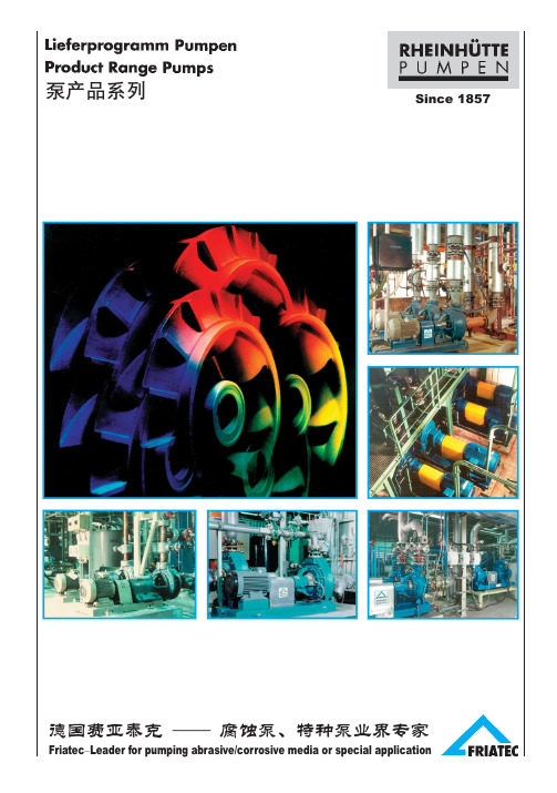
9
Friatec Pump Typical Application: !"#$%&'()*
Basic Chemical Application: Chloralkai electrolysis Caustic soda, Phosphoric Acid, Melt urea, Ammonium nitrate, Fiber, Lime slurry waste Incineration plant, Nitric acid, hydrochloric acid
!
==== !"#$%&'()*+ !"#$%&'( )*+ !"#$ !"#$%&' !"#$% !"# ! !"# !"# $ = = ! = = !" = = ! "#$%&'%( !"#$%&' !"#$%&'() !"#$%&'( !"
A Y Z B C M
^=
_=
`=
j=
2
. The individual groups consist of Rheinhütte’s own developed materials, more than 60 kinds of matericals are available.
RPROF 200 500 2800 12300 6 20 +200
RSU 250 500 2000 8800 5 16 +150
RSP 400 2400 10560 50 164 +200
消防潜水泵
业务手机: 150******** 150********C ATA L O G U E123456789101213业务手机:150******** 150******** 业务手机:150********如需其它样本或询价请来电洽谈。
KQDP 立式多级单吸不锈钢离心泵(KQDP KQDP)产品用途: 高层建筑给水:锅炉给水及冷凝液系统 消防:空调冷、热水循环;水处理、渗透系统、过滤系统 市政供水、增压等..... 工作条件: 流量:1m3/h-21m3/h 扬程:16m-208m 转速:2950r/min 介质: 普通型适用于清水或物理化学介质类似于清水全不锈钢型适用于微碱水、 矿物质水及其他含氯化物液体, 但液体允许温度需要降低 介质温度:-20℃~120℃ 最高工作压力:吸入口压力+泵最大压力≤2.5 Mpa其它品种泵上海凯泉泵业集团简介 ◇荣获“中国驰名商标” “国家免检产品”上海凯泉泵业集团是国内设计、生产、销售泵、给水设备及泵用控制设备的大型综合性泵业公司,是中国 泵行业的龙头企业。
上海凯泉泵业集团注册资金达1.2亿元,总资产达11亿元,拥有9家企业,2个工业园区,总 占地面积500亩,生产性建筑面积12万 M2。
高素质的员工队伍是上海凯泉泵业持续高速发展的源动力。
集团现有员工 4700多人,70%以上员工具有大 专以上学历,其中工程技术人员368名,全国知名水泵专家13人,大学教授2人,享受政府专家津贴5人,教授级 高工22人,工学及商学硕士121人。
高起点、高投入、高品质是凯泉泵业的技术发展战略。
上海凯泉投资组建了市级的“企业技术中心”,每年 斥资3000万元,用于技术创新和新产品研发。
引进了世界先进的 CFD 流体力学专业内流场分析、CAE 有限元 理论计算及 CIMATRON 三维 CAD、CAM、CAE、FMS 等研究设计、生产管理软件系统,并实施 ERP 管理。
凯泉拥有600台/套先进的生产和检验设备,生产23大系列、2万多个品种,年生产能力达20万台/套。
朗克高压油泵系列PC、PD和PS产品说明说明书

CFluid Power Intensifiers Series PC, PD and PScostly way to provide highpressure hydraulic power.■ Maximum Input Pressures:Air - 250 psi (17 BAR);Oil - 1000 psi (69 BAR).■ 3 1/2" to 5 1/2 RAM -3000 psi (206 BAR).■Parker Fluidpower IntensifiersDesigned to Save Energy, Time, Space and Money in a Wide Variety of Applications.A Parker Fluidpower Intensifier is an efficient way of generating high pressure hydraulic fluid. Its operation is quite simple.Pressurized fluid – either air or oil – enters the intensifier and acts on a confined piston. This in turn drives a smaller diameter ram or piston to deliver a given volume of fluid. As a result, the output pressure is intensified and is considerably higher than the input pressure.By using a Parker Intensifier you can save in many ways. First,since it requires only low pressure input and less costly control valving, you eliminate the extra expense of high pressure pumps,valving and a large electrical power sources. The simplermountings and controls also save you valuable installation time.In addition, since Parker Intensifiers produce high hydraulic pressure, you can save space by using a smaller bore hydraulic cylinder in place of a larger bore air cylinder that is heavier and more costly.Finally, because of the rugged dependability of Parker Intensifiers and the simpler circuitry required, you eliminate the constant motion, heat generation and power consumption found in pump systems. This means that you use less energy with less downtime and maintenance.These abilities and benefits of Parker Fluidpower Intensifiers make them the ideal component in many applications. You can use them for such operations as marking, forming, molding,punching, riveting, shearing, straightening, laminating, emboss-ing, welding and testing.What’s more, the Parker Intensifier can be mounted on or off the equipment and can even be integrally combined with the work cylinder. This flexibility makes them particularly useful hydraulic pressure sources on portable equipment.Parker Fluid Intensifiers are available in various sizes andconfigurations. There are cylinder-to-ram units with capability for either single pressure or dual pressure service (left above), as well as several cylinder-to-cylinder models (above right).Here are the features you’ll find in every Parker Fluidpower Intensifier:1. Compact, high-strength steel heads, cap and tie rods meet the most demanding applications.2. Seal by pressure O-rings serve as cylinder body-to-head seals prevent leaks. Thecylinder body is also piloted on the O.D. to insure metal-to-metal contact to support the seals.3. The rugged one-piece iron piston is threaded and Loctited to the ram. Parker Lipseal ®piston seals are used with air;piston rings with hydraulic fluid.4. The driving cylinder body is steel tubing with chrome-plated bore for corrosion-resistance in bore sizes 31/4"through 10". Fiber glass is used on 12" and 14" bore sizes.5. The smooth, wear-resistant surface of the chrome-plated and induction-hardened ram greatly lengthens seal life.6. Static O-ring seals prevent leaks past the O.D. of the glands.Back-up washers prevent extrusion.7. Intensifier operation is speeded up by the free flow of fluid in and out of the unobstructed ports. All high-pressure hydraulic ports are SAE straight thread. O-ring type for leak-proof service.8. Serrated Lipseals ® (Patent 2997318) are self-compensating and self-adjusting to provide leakproof ram seal for both high and low pressure operation.9. For servicing the high pressure ram seals, the pressurechamber is independently secured with studs so it can be easily removed without disassembling the complete intensifier.10. For optimum strength and safety, the pressure chamber wall is made of extra thick steel tubing that is piloted in a counterbore and pressure-welded to the head.This basic circuit is for a dual pressure system supplying pressureto a double-acting work system. The circuit may be readilyA Cutoff ValveB Air Preparation Unit (Filter Regulator Lubricator-Gauge)C 4-Way Valve (Normally 2 Position)D 3-Way ValveTank Fluid Levels)F Advancing Tank (Air-Oil)G Retracting Tank (Air-Oil)H IntensifierI Work Cylinder1234156789810CStep 1: Determine the intensifier ratio for your application. This is the ratio of the available input fluid pressure and the output operating pressure required for the application. For cylinder-to-ram or cylinder-to-cylinder units, use the following formula:Intensifier ratio =Output pressure Input pressureStep 2: Locate the intensifier ratio in column 5 of the appropriate chart on page 3. If the exact ratio is not shown, use the next larger ratio listed. When more than one choice is possible, usually the smallest driving cylinder bore size for a given intensifier ratio is the most economical answer.Step 3: On same horizontal line as ratio determined in Step 2,select the driving cylinder bore size from column 1 and the ram diameter or driven cylinder bore size from column 3.Note: For cylinder-to-ram applications, proceed with Steps 4 and 5. If a cylinder-to-cylinder unit is required, go to Step 6.Step 4: Determine the type of cylinder-to-ram intensifier needed.Generally, a single pressure intensifier is used when the hydraulic work cylinder requires a high pressure for the entire stroke or in test vessel applications. A dual pressure intensifier is recom-mended if the high pressure is to be used only during the last portion of the work cylinder stroke.Step 5: Calculate the intensifier stroke.For single pressure intensifiers, use the formula:Intensifier stroke =V + V cA rFor dual pressure intensifier, use this formula:Intensifier stroke =V h + V cA rWhere: V = Work cylinder volume or test vessel fluid requirementin cubic inches.V h = oil volume in cubic inches required to move the work cylinder piston through its high pressure stroke.V c = compressibility allowance of 1% per 1000 psi of total volume in cubic inches of oil in the high pressure circuit,determined from:V c = total volume x .01 x high pressure/1000.A r = area of intensifier ram in square inches.changed for other operating conditions such as single acting cylinder and single pressure delivery.The input pressure is introduced to the system through shop air lines to the 4-way directional control valve C. When valve C isshifted to position as shown, air is directed into air-oil tank F and to valve D. Oil, acted upon by air pressure, is forced from tank through pressure chamber of retracted intensifier and into work cylinder. The cylinder advances in stroke, being driven by this incoming oil. At a predetermined point in the stroke length of the work cylinder, valve D is synchronized to shift and direct air pressure to the intensifier to drive it in its power stroke, isolating tank F and supplying high pressure to work cylinder for its high thrust stroke. The work cylinder and intensifier are retracted by the shifting of valves C and D simultaneously to exhaust the intensifier and tank F. At the same time, air pressure is directed to tank GHow to Select Parker Fluidpower IntensifiersNote: If the calculated intensifier stroke results in a fraction,correct to the next larger even inch. The recommended maximum stroke is 20". If stroke calculation results in longer than 20" stroke,select a larger driving cylinder and ram having a similar intensi-fier ratio and recalculate stroke.Step 6: For cylinder-to-cylinder intensifiers: Select the properoutput cylinder. Since the output pressure is limited by the cylinder construction, the cylinder should be selected using the maximum pressure to be developed under nonshock conditions.For Parker Series 3L and 2H hydraulic cylinders, the maximum pressures under nonshock conditions are:3L Series:11/2"–2500 psi;2"–2000 psi;21/2"–1800 psi;31/4"–2000 psi;4"–1350 psi;5"–1500 psi;6"–1100 psi;8"–900 psi2H Series: All bore sizes – 3000 psi.General Guidelines1.Intensifiers are generally faster operating when:a. There is adequate input pressure.b. The ports and piping are large enough. Consider the use of oversize ports and connecting lines, to minimize pressure drop.c. The intensifier is pre-exhausted prior to the power stroke.d. Size hydraulic lines so that fluid flow velocity does not exceed 7 feet per second.2.Bypass the intensifier with a pre-fill low pressure line by direct connection through a check valve to the pressure vessel.3.Regulate the driving pressure to the intensifier to achieve the required high pressure output.4.Keep all piping lengths to a minimum by having the tanks,intensifier and pressure vessel as close together as possible.5.A single pressure intensifier usually provides faster cylinder action because it does not need to change from low to high pressure but instead immediately supplies the high pressure.6.Intensifiers are generally used in circuits where limited quantities of high pressure fluid is required.and to rod end side of intensifier piston. Oil from tank G retracts cylinder at low pressure.The operators for valves C and D are optional – mechanical,manual, pilot or solenoid. The method of synchronizing valve D to stroke length position of work cylinder is also optional. This may be done by pilot control, limit switch, pressure switch, mechani-cally such as cams, or manually.*This 2" is the intensifier stroke advance necessary to close the high pressure seal on dual pressure intensifiers only.+ 2"*Fluidpower IntensifiersSelection Sizing(Series PS and PD) Cylinder to Ram Intensifiers1000Col. 11345026404000256040002780204040002940500Col. 102795172513204230261520001280408031252000139010204500288020001470355516154080200Col. 9211411186905283200169210468005125002264416321250800556408381023521800115280058841803200104814221046500032002222163246083200235043563200100Col. 82702105755934526440931600846523400256250113228166254002782043601190511769005764002943385209016001024711523326625001600111181647023600230416001175489931362178160080Col. 7216184644727621132741280677418320205511620001058653500320222163288015249417204613202355122270816721280819569418423126132000128088965337612880184312809405120391925091742128050Col. 61351529280173132204680042326220012831971250661408313200139102180095358845028820014732011693104580051235626226441633125080055640838082351180011528005883200244915681089800IntensifierRatio Col. 527.0210.575.593.452.6440.9316.008.465.234.002.5663.9525.0113.228.166.254.002.782.0436.0119.0511.769.005.764.002.9464.0333.8520.9016.0010.247.115.2352.8932.6625.0016.0011.118.1676.1647.0236.0023.0416.0011.7564.0048.9931.3621.7816.00Area of VolumeD ispl. Per in StrokeCol. 4.307.7851.4852.4053.142.307.7851.4852.4053.1424.909.307.7851.4852.4053.1424.9097.0699.621.7851.4852.4053.1424.9097.0699.621.7851.4852.4053.1424.9097.0699.6211.4852.4053.1424.9097.0699.6211.4852.4053.1424.9097.0699.6212.4053.1424.9097.0699.621Dia.Col. 35/811 3/81 3/425/811 3/81 3/422 1/25/811 3/81 3/422 1/233 1/211 3/81 3/422 1/233 1/211 3/81 3/422 1/233 1/21 3/81 3/422 1/233 1/21 3/81 3/422 1/233 1/21 3/422 1/233 1/2Area Col. 28.29612.56619.63528.27450.26578.540113.10153.94Bore Col. 13 1/44568101214Driving Cylinder Hydraulic RamTheoretical IntensifiedHydraulic Pressure (PSI) UsingAn Input Pressure Of(Series PC) Cylinder to Cylinder Intensifiers1000Col. 112640*4000*2560*4000*2370*3410*2250*14404000*2560*1780*4000*2780*4000*2940*2250*4000*3060*500Col. 10234513203555*200012803125*2000*11854500*2880*170511257203030*2000*12808904735*3125*2000*1390*4500*2880*2000*1470*1125*3920*1725*2000*1530*200Col. 9938528142280051222221250800474180011526824501883200*204812128005123563200*189412508005562728*1800*1152800588*4502450*1568*1090800*612100Col. 846926471140025611116254002379005763412251441600102460640025617816009476254002781364900576400294*2251225784545400*30680Col. 7375211569320205889500320190720461273180115128081948532020514312807585003202231091720460320235*180980227436320*24550Col. 62351323562001285563132001194502881711137280051230320012889800474313200139682450288200147*113613392273200*153Intensifier Ratio Col. 54.692.647.114.002.5611.116.254.002.379.005.763.412.251.4416.0010.246.064.002.561.7816.009.476.254.002.7813.649.005.764.002.942.2512.257.845.454.003.06Area Col. 41.7673.1421.7673.1424.9091.7673.1424.9098.2963.1424.9098.29612.56619.6353.1424.9098.29612.56619.63528.2744.9098.29612.56619.63528.2748.29612.56619.63528.27438.48550.26512.56619.63528.27438.48550.265Bore Col. 31 1/221 1/222 1/21 1/222 1/23 1/422 1/23 1/4452 2 1/23 1/44562 1/23 1/44563 1/44567845678Area Col. 28.29612.56619.63528.27450.26578.540113.10153.94Bore Col. 13 1/44568101214Driving Cylinder Theoretical Intensified Hydraulic Pressure (PSI) UsingAn Input Pressure OfDriving Cylinder *Not recommended for Series 3L driven cylinder, use Series 2H.Cylinder to Cylinder Intensifier – Series PCCFluidpower IntensifiersDimensions and MountingsParker Fluid Power Cylinder to Cylinder Intensifiers (Series PC)Series PC Intensifiers consist of two cylinders joined into an integral unit with one piston driving a second piston of smaller diameter. These intensifiers are not self-bleeding or self-filling, therefore, for the most effective operation, it is recommended that these tasks be done manually.Special Note: It is recommended that Series PCcylinder-to-cylinder intensifiers be mounted vertically with the smaller cylinder up.MTG Styles are:HBA – Air Input HBL – Hyd. InputMounting Style TCCap Tie Rods ExtendedThis mounting available in driving cylinder bore sizes 31/4-inches through 14-inches.MTG Styles are:TCA Cap End – Air Input TCL Cap End Hyd. InputAPSFluidpower IntensifiersDimensions MountingsParker Fluid Power Cylinder to Ram Dual Pressure Intensifiers (Series PD)Series PD Intensifiers are similar to the Series PS units except a center head has been added to retain another gland and a third ram seal. When the ram is fully retracted, it withdraws from this third seal, allowing the low pressure the low pressure hydraulic fluid to flow through the port in the center head. The fluid then goes past the ram and out the pressure chamber port to prefill and advance the work cylinder. Actually, this third seal and the ram act as a check valve. As the circuit sequences, the ram advances into the seal to close this “valve” and build up highpressure. With this arrangement and the proper mounting, Series PD intensifiers are self-bleeding and self-filling. And theseSpecial Notes: 1. When equipped with integral air-oil tanks, Series PD intensifiers have a maximum input pressure of 150 psi.2. It is recommended that Series PD dual pressure intensifiers be mounted vertically with the pressure chamber down.Mounting Style CB –End AnglesMounting Style TBHead Tie Rods Extended(Styles TC – Cap Tie Rods Extended and TD – Both Ends Tie Rods Extended are also available. Dimensions “BB”remains the same in all cases.)Mounting Style TBHead Tie Rods Extended with Integral Air-Oil Tank Mounting Style CB –End Angles with Integral Air-Oil Tanks+CParker Fluid Power Cylinder to Ram Single Pressure Intensifiers (Series PS)Series PS Intensifier delivers a single pressure through a double acting piston driving a ram. One seal on the ram gland works on the driving piston side; the other on the pressure chamber side. Since this intensifier is neither self-bleeding nor self-filling, for best performance it is recom-mended that these tasks be performed manually.Special Note: It is recommended that Series PSsingle pressure intensifiers be mounted vertically withMounting Style CB – End AnglesMounting Style TCCap Tie Rods Extended(Style TB – Head Rods Extended, and TD – Both Ends Tie Rods Extended, are also available. Dimension “BB” remains the same in all cases.)Fluidpower IntensifiersDimensions and MountingsWARNINGFAILURE OR IMPROPER SELECTION OR IMPROPER USE OF THE PRODUCTS AND/OR SYSTEMS DESCRIBED HEREIN OR RELA TED ITEMS CAN CAUSE DEA TH, PERSONAL INJUR Y AND PROPERTY DAMA GE.This document and other information from Parker Hannifin Corporation, its subsidiaries and authorized distributors provide product and/or system options for further investigation by users having technical expertise. It is important that you analyze all aspects of your application, including consequences of any failure and review the information concerning the product or system in the current product catalog. Due to the variety of operating conditions and applications for these products or systems,the user, through its own analysis and testing, is solely responsible for making the final selection of the products and systems and assuring that all performance,safety and warning requirements of the application are met.The products described herein, including without limitation, product features, specifications, designs, availability and pricing, are subject to change by Parker Hannifin Corporation and its subsidiaries at any time without notice.!How To OrderWhen ordering Parker Intensifiers, please specify:a. Quantityb. Driving Cylinder bore sizec. Mounting style – specify by using style letters given beneath dimension drawings.d. Driving cylinder operating fluid mediume. Intensifier series (PS, PD or PC)How To Order Parker Fluidpower IntensifiersModel NumbersEach Parker Fluidpower Intensifier has a model number.This, along with the driving cylinder bore size and stroke,is an accurate and coded description of the unit. The chart When Ordering Fluid Power Intensifiers By Model Numberf. Intensifier ram diameter (for cylinder-to-ram intensifiers)or Output cylinder bore (for cylinder-to-cylinder units)g. Driving cylinder strokeh. Input pressure, output pressure and volumeNote: Standard intensifiers are designed for use with petroleum base hydraulic oil. If other fluids will be used,please consult the factory.here shows the elements of these model numbers. It is provided so that you can check our order acknowledgement against your order.Intensifier Ram (or D riven Cylinder)Diameter Specify From Dimension TablesDriving Cylinder Bore 3 1/4,4, 5, 6,8, 10,12 or 14Driving Cylinder Mounting Style CB,TB, TC,TD, H or HB Driving Cylinder Operating Fluid 2A (Air)or 3L* (HYD.)SpecifyOne SeriesOnlyIntensifier SeriesPD,PS, PC Driven Cylinder Series PC Only 2H (3000 PSI Maximum)or 3L (900 to 2500 PSI Maximum Depending on Bore SizeSpecial FeaturesS Use Only if Intensifier Varies From CatalogDriving Cylinder Stroke Specify For PD Style See Note Below–X NOTE: PD style intensifiers require 2" additional stroke to seal the high pressure end. See Page 61.*3L supplied with cast iron piston rings unless otherwise specified.SpecificationsMaximum Input Pressures:Air - 250 psi (17 BAR); Oil - 1000 psi (69 BAR).Maximum Output Pressures:5/8" to 3" RAM - 5000 psi (345 BAR);3 1/2" to 5 1/2 RAM - 3000 psi (206 BAR).Maximum Operating Temperatures:-10°F to +165°F (-23°C) to (+74°C).。
石油化工流程泵型号及参数
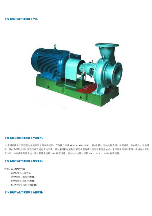
【ZA系列石油化工流程泵】产品:【ZA系列石油化工流程泵】产品简介:ZA系列石油化工流程泵为单级单吸悬臂式涡壳泵,产品执行标准API610,VDMA24297(轻/中型),泵体为脚支撑,单吸叶轮,轴向吸入,径向排出。
轴向力采用前后口环及平衡孔进行水力平衡。
轴封采用机械密封可采用单端面或双端面平衡型集装式,也可以采用填料密封。
机械密封并配有冷却、冲洗或密封液系统,密封管路系统按 API 规范设计。
吸入与排出法兰可按 GB 、 DIN 、 ANSI 标准设计。
【ZA系列石油化工流程泵】型号意义:例如:ZA100-50-315ZA-石油化工流程泵100-泵进口直径100(mm)50-泵排出口直径50(mm)315-叶轮名义直径315(mm)【ZA系列石油化工流程泵】性能范围:流量Q可达2600m³/h;扬程H可达250m;工作压力P可达2.5MPa;工作温度T-80℃~+450℃;口径φ25~400mm;转速:1450-2900r/min。
泵过流部件材料有不锈钢材质有304、304L、316、316L、CD-4MCu、 904、904L、哈氏合金等。
【ZA系列石油化工流程泵】产品特点:ZA系列石油化工流程泵为单级单吸悬臂式后开门的结构,所以在检修泵时不需拆卸吸入和排出管路,拆开泵盖后即可将悬架连同转子部件一起从泵体中抽出,所以检修工作十分方便。
叶轮的后盖板上有密封环,基本上能平衡轴向力,残余的不平衡力由推力轴承承受。
轴承为油润滑的球轴承,油环提油而且能自动控制油位,当工作温度低于250℃时,悬架无需冷却,工作温度高于250℃~450℃时,悬架用风冷或水冷。
根据不同的情况,部分泵为双蜗壳结构,其余为单蜗壳。
轴封可采用填料密封,也可采用单端面或双端面机械密封,并配有冷却、冲洗或接密封液的系统。
由电动机直接驱动,用联轴器与电动机相连。
【ZA系列石油化工流程泵】产品用途:ZA系列石油化工流程泵适合于输送清洁的或含少量颗粒的、低温的或高温的液体;适合于输送中性的或有腐蚀性的液体,其中包括各种温度和浓度的氢氧化钠和碳酸钠等碱性溶液、各种盐溶液、各种酸溶液和盐溶液、各种液态石油化工产品、有机化合物以及其它有腐蚀性的原料和产品。
KCC系列化工泵介绍资料

名称
泵体 泵盖 叶轮 轴 密封环(组) 轴承(组) 机械密封 填料 轴套 机封压盖 O形圈/垫(组) 联轴器(套)
同规格泵的数量(台)
1~3
4~6
7~9
≥10
备件的数量(件)
1
1
1
1
2
N/3
1
1
2
N/3
1
1
2
N/3
1
2
N/3
N/3
1
2
N/3
N/3
1
2
N/3
N/3
1
2
N/3
N/3
1
2
N/3
1
2
N/3
N/3
*泵和电机应对中调整,调整完成后再装中间轴和膜片,并用螺栓紧固。 用百分表或量尺校正(见图4和图5),调整后的允许误差为:两轴的径向偏差≤0.1~0.2mm;轴向
位移≤1~1.5mm;端面跳动(角误差)≤0.1~0.2mm。 在泵机组及连接管路安装好后,还必须重新校正泵、驱动机及联轴器之间的同轴度。
φ 65×φ
A1.330.01 80×50-200
4×2×105 72×2 34.5×2.65
28×1.8
100×80-160
125×2.65
NSK NSK
100×65-200
230×3.55
7308A NU308
125×100-
65×40-250 φ φ 290 80×50-250 (TG.413.280
零件代号 637 638* 640 912.1 912.2 922 923 931 940.1 940.2 941 970
零件名称 油孔盖 恒位油杯 油标 六角螺塞 叶轮螺母 小圆螺母 圆螺母止退垫 平键 薄型平键 半圆键 铭牌
CR型格兰富水泵说明书
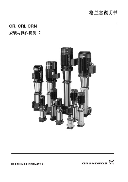
图3 9 最小入口压力的计算方法:
4.9 尺寸和重量 尺寸:请参见第 69 页图 C。 重量:请参见包装上的标签。
4.10 噪音等级ຫໍສະໝຸດ 请参见第 30/31 页图 D。5.安装
泵必须用螺栓通过法兰孔或者泵座孔安全在可靠的坚实的基 础上。 在安装泵时,必须严格按照以下过程序进行操作,以免损坏泵。
步骤
安装方法
4.5 最大进口压力 第 27/28 页图 B 标示了进口最大压力。但是,泵入口压力加 泵在闭阀时的扬程必须低于最大允许压力。 应该如第 27/28 页图 B 所示,压力测试在所示压力的 1.5 倍 下进行。
4.6 最小流量 由于过热的危险,泵不应该工作在最小流量状态下。 下图显示在相应温度下,最小流量占正常流量的百分比。 虚线为空气冷却曲线顶点。
CR, CRI, CRN
安装与操作说明书
格兰富说明书
设计标准申明
我们格兰富公司申明:在我们销售的职责范围内,对于 CR,CRI 和 CRN 型号的产品,符合欧共体成员国试行法工作委员会指 令性文件,相关文件如下: —机械(98/37/欧共体).
采用标准:EN ISO 12100.[译者注:英语 国际标准 12100] —电磁相容性(89/336/欧洲经济共同体).
·安装有功率最大为 11kW 的格兰富 MG 电机的 CR,CRN 32,45,64,90 泵,应该通过提升泵端部的环状螺母来提升 泵。
·安装有功率在 15kW 以上的西门子电机的 CR,CRN 32,45, 64,90 泵,应该通过提升电机法兰上的的环状螺栓来提升泵。
·对于安装除上述之外的其它型号的电机的泵,建议用皮带等
在开始安装之前,应该仔细阅读如下安装和操作
说明。安装和操作也应该参照当地的有关法规或
化工泵的选型原则
化工泵的选型原则1、输送介质的物理化学性能:输送介质的物理化学性能直接影响泵性能、材料和结构。
介质的物理化学性能包括:名称、特性(腐蚀、磨蚀、毒性等)、颗粒大小及含量、密度、粘度、汽化压力等。
必要时还应列出介质中的气体含量,说明介质是否容易结晶等。
2、工艺参数:工艺参数是泵选型的重要依据,应根据工艺流程和操作变化范围慎重考虑。
流量Q:工艺装置中要求泵输送的介质量,应给出正常、最大、最小流量。
选泵时,要求泵额定流量不小于装置的最大流量,或取正常流量的1.1~1.15倍。
扬程H:工艺装置所需要的扬程值,也称为计算扬程。
一般要求泵额定扬程为装置所需扬程的1.05~1.1倍。
进口压力Ps和出口压力Pd:指泵进出接管法兰处的压力,进出口压力大小影响到泵壳的耐压和轴封的要求。
温度:泵进口温度,一般给出正常、最高、最低温度。
装置气蚀余量NPSHa:也称为有效气蚀余量。
操作状态:连续或间断运行。
二、泵类型的选择选泵类型应根据装置的工艺参数、输送介质的物理和化学性质、操作周期和泵的结构特性等因素合理选择。
离心泵具有结构简单,输送液体无脉动,流量调节简单等优点,所以除以下情况外,要尽可能地选用离心泵。
有计量要求时选用计量泵;扬程很高流量很小且无合适小流量高扬程离心泵可以选用时可选用往复泵;如气蚀要求不高时也可以选用旋涡泵;扬程很低流量很大时选用轴流泵或混流泵;粘度较大(650~1000mm2/s)时,可以考虑选用转子泵或往复泵,粘度特大时,可以选用特殊设计的高粘度转子泵和高粘度往复泵;介质含气量>5%,流量较小且粘度小于37.4mm2/s时,可以选用旋涡泵。
如允许流量有脉动,可以选用往复泵。
对启动频繁或灌泵不便的场合,应选用具有自吸性能的泵,如自吸式离心泵、自吸式旋涡泵、容积泵等。
三、泵系列和材料的选择泵的系列是指泵厂生产同一类结构和用途的泵,如IH、CZ、IJ、ZA型化工流程泵,AY型油泵,ZE型石油化工流程泵等。
塑料自吸泵型号及参数
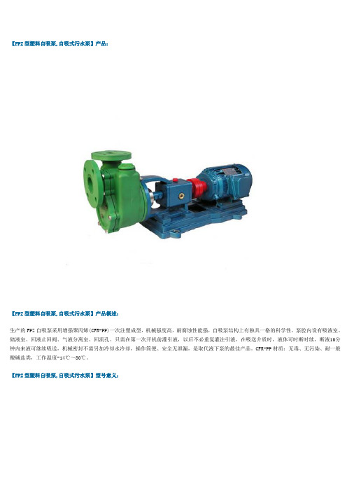
【FPZ型塑料自吸泵,自吸式污水泵】产品:【FPZ型塑料自吸泵,自吸式污水泵】产品概述:生产的FPZ自吸泵采用增强聚丙烯(CFR-PP)一次注塑成型,机械强度高,耐腐蚀性能强,自吸泵结构上有独具一格的科学性,泵腔内设有吸液室、储液室、回液止回阀、气液分离室、回流孔。
只需在第一次开机前灌引液,以后不必重复灌注引液,在吸送介质时,液体可时断时续,断液15分钟内来液可继续吸送,机械密封不需另加冷却水冷却,操作简便、安全无泄漏,是取代液下泵的最佳产品。
CFR-PP材质:无毒、无污染、耐一般酸碱盐类,工作温度-14℃~80℃。
【FPZ型塑料自吸泵,自吸式污水泵】型号意义:【FPZ型塑料自吸泵,自吸式污水泵】产品特点:FPZ型塑料自吸泵具有体积小、重量轻、结构简单、使用方便、效率高,价格低。
泵体内腔光滑,叶轮为闭式,采用机械密封和耐橡胶圈密封等二种,全轴为不锈钢用套筒式连接。
输送介质温度为-20℃~80℃,流量:4-25m3/h 扬程:7-25m转速2900r/min【FPZ型塑料自吸泵,自吸式污水泵】主要用途:FPZ型塑料自吸泵主要用于输送酸,碱,盐等腐蚀性液体,但不得用于输送若干对ABS工程塑料有显著作用的化学品,如芳烃、脂肪烃的卤素衍生物,酮类及浓酸碱等。
【FPZ型塑料自吸泵,自吸式污水泵】性能参数:型号流量m3/n扬程mm自吸高度m自吸时间s/m功率kw进出口径mm与电机轴联接形式25FPZ-10(D) 2.5103600.75 1 1/2直联式32FPZ-11(D) 3.5113600.75 1 1/2直联式40FPZ-18(D)1118460 1.540/30直联式50FPZ-20(D)1320460 2.250/40直联式25FPZ-10 2.5103600.75 1 1/2联轴式32FPZ-11 3.5113600.75 1 1/2联轴式40FPZ-181118460 1.540/30联轴式50FPZ-201320460 2.250/40联轴式65FPZ-282028460465/50联轴式80FPZ-3050304607.580/65联轴式【FPZ型塑料自吸泵,自吸式污水泵】结构示意图:声明:由于产品一直在更新,本文中所有文字、数据、图片均只适用于参考怎样选择水泵?建议从五个方面加以考虑,既液体输送量、扬程、液体性质、管路布置以及操作运转条件等。
美国WILDEN气动隔膜泵P200用户手册
PS200Advanced TM塑料泵系列WILDEN目录第一部分:注意事项 (3)第二部分:泵编码系统 (5)第三部分:工作原理(泵与空气系统) (7)第四部分:轮廓图 (9)第五部分:工作性能曲线A.P200 ADVANCE TM塑料泵橡胶配件 (11)B.P200 ADVANCE TM塑料泵热塑性弹性体(TPE)配件 (12)C.P200 ADVANCE TM塑料泵特氟隆(PTFE)配件 (13)第六部分:吸程曲线与数据 (14)第七部分:安装及操作A.安装 (15)B.推荐操作方法与维修说明 (17)C.故障检修 (18)第八部分:拆卸与重装说明A.P200 ADVANCE TM塑料泵的拆卸与重装说明 (19)B.Pro-Flo®气阀/中心体——拆卸、清洁、检验 (24)C.重装说明,转力矩规格(锣栓松紧) (28)第九部分:分解图/配件清单A.P200 ADVANCE TM塑料泵——用螺栓固定橡胶配件 (29)B.P200 ADVANCE TM塑料泵——用螺栓固定特氟隆配件 (31)第十部分:弹性体选择 (33)第一部分:注意事项—必先阅读温度限度:接液部件:聚丙烯(PP)聚偏(二)氟乙烯(PVDF)氟塑料树脂(PFA)0℃~ 79.4℃-12.2℃~107.2℃-28.9℃~ 87.8℃32℉~175℉10℉~225℉-20℉~190℉弹性体:氯丁(二烯)橡胶丁(二烯)-(丙烯)橡胶/丁腈橡胶(Buna-N)三元(乙丙)橡胶(EPDM)氟化橡胶(VITON®)Wil-Flex TM聚(亚)氨酯Tetra-Flex TM特氟隆带氯丁橡胶背衬Tetra-Flex TM特氟隆带三元橡胶背衬聚四氟乙烯/特氟隆(PTFE)-17.8℃~ 93.3℃-12.2℃~ 82.2℃-51.1℃~137.8℃-40.0℃~176.7℃-40.0℃~107.2℃12.2℃~ 65.6℃4.4℃~107.2℃-10.0℃~137.0℃4.4℃~104.4℃0℉~200℉10℉~180℉-60℉~280℉-40℉~350℉-40℉~225℉10℉~150℉40℉~225℉14℉~280℉40℉~220℉*通过选择不同的弹性体可以改变温度限度。
格兰富CR泵样本解读

CR, CRN高压GRUNDFOS DATA BOOKLET立式多级离心泵50 Hz目录产品数据性能范围介绍产品范围应用CRNE 1及3 HSCRN 5, 10, 15, 20 SF2 x CR 32, 45, 64, 902 x CRN 32, 45, 64, 902 x CRN 120, 1502 x CRN 120, 150型号说明代码高压泵轴封运行范围接线盒位置输送液体性能曲线适用原则选型和尺寸CR, CRN高压泵的选型性能曲线/技术数据CRNE 1-HS, 50/60 HZCRNE 3-HS, 50/60 HZCRN 3-SF , 50 HZCRN 5-SF, 50 HZCRN 10-SF, 50 HZCRN 15-SF, 50 HZCRN 20-SF, 50 HZCR 32, 50 HZCRN 32, 50 HZCR 45, 50 HZCRN 45, 50 HZCR 64, 50 HZCRN 64, 50 HZCR 90, 50 HZCRN 90, 50 HZCR 120,50 HZCRN 120,50 HZCR 150,50 HZCRN 150,50 HZ电气数据CR,CRN 高压泵标准电机 , 50HZE 电机,CRN HS , 50HZE 电机,CRN SF , 50HZCR,CRN 高压泵标准电机 , 60HZE 电机,CRN HS , 60HZE 电机,CRN SF , 60HZ 附件管路连接用于CRN 的对接法兰转接组件PJE 连接器带接管连接管PJE 连接器不带管CRNE-HS 用压力传感器LiqTecWEBCAPS234556788991010111111111214161820222426283032343638404244464850525252535353545454555555565657产品数据CR,CRN 高压泵性能范围T M 02 1689 400734产品数据CR,CRN 高压泵介绍本样本针对C R,C R N 泵的高压应用,两种方法获得高压:● 单台泵,配内置变频器的高速电机-CRNE-HS 1&3● 双泵串联,给水泵+高压泵-CRN-SF 3到20-CR,CRN 32到150依据泵的型号不同,高压泵共有两种结构形式:● CRNE-HS 和CRN-SF与标准泵相比,流道腔反置● CR,CRN :标准泵或加装轴承法兰高压泵得到的高压力是由泵的特殊设计实现的。
CPKN化工泵

KSB泵产品目录_机械/仪表_工程科技_专业资料。离心 泵化工耐腐蚀 塑料 磁力...CPK CPK D CP K - HCPKNCPKO CPP CT N Etabloc. E t a b l oS ...
KSB水泵特性曲线,800T,40M,CPKN-250-400性能曲线
性能曲线 客户项目编号: 合同日期: 15/02/2012 订单编号: Michellin 数量: 1CPKN-E 250-400化工标准泵符合EN22858/ISO 2858/ISO 5199 标准 Qm in No.:...
第1页下一页
Word文档免费下载:CPKN化工泵(共17页,当前第1页)
CPKN化工泵
化工泵上海阳光泵业
化工泵
耐腐蚀化工泵
英格索兰化工泵
立式化工泵
自吸化工泵
不锈钢化工泵
ih化工泵
CPKN化工泵
CPKNch
CPKNch_能源/化工_工程科技_专业资料。ChemienormpumpeCPKNISO- Norm 5199重新定义过. CPK泵一直保持 固定的尺寸大小 ... ...CPKN是对CPK 的一项重要改...
©2012文档网, |站点地图|文档上传|侵权投诉|手机版
本站资源均为网友上传分享,本站仅负责收集和整理,有任何疑问请联系我们
H = 保温模式O = 开式叶轮
F = 非标法兰设计K = 强冷却轴密封腔X = 特殊设计A = 带锥形密封腔
结构
卧式、径向剖分式蜗壳,后盖可拆卸,径向叶轮,单级单吸,符合EN 22 858 / ISO 2858 / ISO 5199
标准。
运行参数
流量扬程泵规格运行压力运行温度运行温度
认证
FZB氟塑料合金自吸泵规格型号及参数大全

上海沈泉泵阀制造有限公司■产品概述1.上海 泵阀制造有限公司生产的FZB、FZB-L 型氟塑料合金自吸泵,适合于在-85℃,120℃温度的条件下长期输送任意浓度的任意介质:酸、氧化剂及腐蚀性介质(禁输快速硬质结晶体介质),过流部分全部采用聚四氟乙烯和聚全氟乙丙烯等多种氟材料经过合理配方模压,加工而成,它集多种氟塑料之优点,具有特强的耐腐蚀性,并具有机械强度高,不老化,无毒素分解等优点.2.FZB、FZB-L 型自吸泵是根据广大化工行业用户的要求,设计的新型氟塑料合成耐腐蚀系列产品,该泵采用外混式自吸结构,除首次启动前须向泵体注满溶液,以后的频繁启动不需灌注引水或抽排真空,操作方便,安全省事。
该产品广泛适用于化工、石油、制药、农药、油漆、冶炼、造纸、电镀、食品等行业。
密封采用英国格兰盘根公司与国内联合生产的机械密封,自试制、生产使用几年来在市场上享有耐腐蚀之最的美名。
目前,是杜绝跑、冒、漏、滴建设文明工厂的理想防腐输送设备。
3.EZB、FZB-L 型氟塑料合金自吸泵系列产品的生产、制造及验收规范,严格执行了有关标准规定,并台台检测,备案待查,以保证系列产品的质量.4.性能范围与型号说明:FZB、FZB-L 型系列耐腐蚀泵,全系列共5个型号,10个规格。
流量范围1-50m3/h,扬程范围10-25m.■型号意义■性能技术规范口径 规格型号流量(m3/h) 扬程(m) 吸入mm 吐出mm 配用电机(KW)转速(r/min)吸上高度m 轴功率 Pa 效率%40FZB-25 8 25 40 32 2.2 2900 4 1.05 52 40FZB-30 8 30 40 32 3 2900 4 2.2 49 50FZB-25 120 25 500 400 30 29000 4 2.20 50 50FZB-30 120 300 500 400 40 29000 4 3.1 49 65FZB-25 250 25 650 500 5.50 29000 5.5 4.10 58 65FZB-30 250 300 650 500 7.50 29000 5.5 5.80 56.8 80FZB-25 400 250 800 650 7.5 29000 5.5 5.80 60 80FZB-30 400 300 800 650 7.50 29000 5.5 6.20 59.9 100FZB-25 800 250 1000 800 7.5 29000 4 5.80 65 100FZB-30 80 30 100 80 11 2900 4 8.2 67 100FZB-40804010080152900414.872沈泉■工作原理1.泵体 2.叶轮3.后盖4.压盖5.密封件 6.支架7.电机轴 8.吊紧螺栓9.电机A(FZB型)一、FZB型氟塑料泵由泵体、叶轮、后盖、压盖、螺丝、静环、动环、支架、电机组成。
2020年中国氟塑料化工泵十大品牌总评榜
2020年中国氟塑料化工泵十大品牌总评榜2020年度中国氟塑料化工泵十大品牌评选” 是由品牌排行网主办的全网范围最广、规模最大的品牌综合实力排名评选活动。
此次评选,征集数万网友投票、点评,经过多轮审核精选出行业品质出众、人气最旺的十大品牌。
品牌排行网致力于推动中国消费方式品牌化,构建良好的消费环境。
活动创办以来反响热烈,不但吸引了国内近一半的品牌和经销商的参与,同时,也被新浪、网易、人民、新华、中国网等70多家知名网媒高度关注,共享品牌盛宴。
中央电台、人民日报等权威媒体报道,为国内优秀品牌团聚人气,提高品牌知名度、影响力提供契机。
荣登“2020年度中国氟塑料化工泵十大品牌”榜单的优秀企业和品牌如下:1.上海阳光泵业制造有限公司上海阳光泵业是集设计/生产/销售泵、给水设备及泵用控制设备于一体的大型综合性泵业集团,是中国泵行业的龙头企业。
总资产达38亿元,在上海、浙江、河北、辽宁、安徽等省市拥有7家企业,5个工业园区,占地面积67万平方米,建筑面积35万平方米。
上海阳光获得了“上海市质量金奖”、“上海市科技百强企业”、“上海市名牌产品”、“中国质量信用AAA级”、“全国合同信用等级AAA级”、“质量、信誉、服务三优企业”、“中国最具竞争力的商品商标”、“五星级服务认证”等荣誉,连续多年入选全国机械500强。
高端人才和高素质的员工队伍是阳光发展的动力。
集团现有员工4500余人,其中工程技术人员500多名,主要由国内知名水泵专家教授、博士硕士、中高级工程师、高级工艺师组成,形成了具有创新思维的梯队型人才结构。
科技创新,是阳光基业长青的生命之源。
集团是上海市高新技术企业、上海市知识产权示范企业和上海市专利示范企业。
上海市级的“企业技术中心”,每年以销售总额的5%,用于技术创新和新产品研发。
2.江苏多为泵业股份有限公司江苏多为泵业股份有限公司是国内知名的以泵业经营为主业,涉及电机、阀门、电控系统、环保节能、机械铸造、热交换机、空压机、减速机、电气产品、压力容器等相关领域,集科研、制造、营销、服务为一体的科、工、贸企业集团。
雷博德油泡式泵产品说明书

particle filter elements (WF AluPart), sealed during shipping , are supplied .
The CFS is precleaned so that it can be used with either mineral oil (e. g. N 62 or HE-200) or perfluoropolyether (PFPE, e. g. NC 1/14 or HE 1600). For shipping it is sealed airtight in foil, together with silica gel.
Waste oil from vacuum pumps (Leybold oils which are based on mineral oils) which are subject to normal wear and which are contaminated due to the influence of oxygen in the air. high temperatures or mechanical wear must be disposed of through the locally available waste oil disposal system.
3
Filter Change . •. ... .• .. ••. . ..• .. • ...18
3.1 Leybold Service .. .. • . •... . .. . .. . .....20
Warning Indicates procedures that must be strictly
