FRONIUS 使用和保养手册
TPS(奥地利福尼斯)焊机使用说明书
由于监控系统对实际焊接参数与设定参数进行数字 式的比较并及时调整,因而这种焊机创造了迄今为 止独一无二的、无可比拟的精确度,无与伦比的焊 接质量,并具最佳的焊接特性。
机器原理
这种新型机器的的典型特性是具有巨大的适应性 能,极其容易地胜任各种各样的任务。这些受欢迎 的特性不但在标准化组件设计上能看到,而且在系 统提供的错误自检,扩展功能上也能体现。
MIG/MAG 焊-------------------------29
暂停引弧功能 断弧监测功能 手工模式 无飞溅引弧 双脉冲 专为机器人设计的特殊 2 步模式
手工电弧焊----------------------------------32
热起弧功能 恒能特征曲线 焊条防粘功能
TIG 焊---------------------------------34
TIG 焊软收弧功能
JOB 工作方式-------------------------------35
在工作序号中存储焊接程序 复制/覆盖工作 删除工作 调用 JOB 中的焊接程序 在 JOBMASTER 焊枪切换工作程序 枪开关选项 JOB(工作调整功能)
第一层设置菜单-------------------------------41
2 步模式 4 步模式 焊铝特殊程序 点焊 控 制 和 连 接 -------------------------------------11 TPS 2700 电源 TS 4000/5000&TPS 4000/5000 电源 VR 4000/ VR 4000C/ VR 4000CI 送丝机 VR 7000/ VR 7000CI 送丝机 VR2000 送丝机 FK 4000/4000 R 水冷系统 JobMaster 焊枪 TR 2000 遥控器 TR 4000 遥控器 TP 08 遥控器 RCU4000 遥控器 RCU 4000 遥控器 内部网络分配器 内部网络
欧普斯莫尔恩熔断器启动切断开关操作和维护手册说明书

O p e r at i O n a n dM a i n t e n a n c e M a n ua lf u s i b l es h u n t t r i p sw i tc h2 • Fusible Shunt Trip SwitchENCLOSED INDUSTRIAL CONTROL PANELFusible Shunt Trip SwitchDevice Overview . . . . . . . . . . . . . . . . . . . . . . . . . . . . . . . . . . . . . . . . . . . . . . . . . . . . . . . . . . . . . . . . . . . . . . . . . . . . . .2Installation Instructions . . . . . . . . . . . . . . . . . . . . . . . . . . . . . . . . . . . . . . . . . . . . . . . . . . . . . . . . . . . . . . . . . . . . . . . .3Catalog Number Selection T able . . . . . . . . . . . . . . . . . . . . . . . . . . . . . . . . . . . . . . . . . . . . . . . . . . . . . . . . . . . . . . . .4Motor Fuse Selection T able . . . . . . . . . . . . . . . . . . . . . . . . . . . . . . . . . . . . . . . . . . . . . . . . . . . . . . . . . . . . . . . . . . . . .5Wiring Diagram – 120VAC Control Interface . . . . . . . . . . . . . . . . . . . . . . . . . . . . . . . . . . . . . . . . . . . . . . . . . . . . . .6Wiring Diagram – 24V (AC or DC) Control Interface . . . . . . . . . . . . . . . . . . . . . . . . . . . . . . . . . . . . . . . . . . . . . .7T orque Specifications . . . . . . . . . . . . . . . . . . . . . . . . . . . . . . . . . . . . . . . . . . . . . . . . . . . . . . . . . . . . . . . . . . . . . . . . . .8Maintenance . . . . . . . . . . . . . . . . . . . . . . . . . . . . . . . . . . . . . . . . . . . . . . . . . . . . . . . . . . . . . . . . . . . . . . . . . . . . . . . . . .9Warranty . . . . . . . . . . . . . . . . . . . . . . . . . . . . . . . . . . . . . . . . . . . . . . . . . . . . . . . . . . . . . . . . . . . . . . . . . . . . . . . . . . . . .9FAQs (Frequently Asked Questions) . . . . . . . . . . . . . . . . . . . . . . . . . . . . . . . . . . . . . . . . . . . . . . . . . . . . . . . . . . . .9Spare Parts List . . . . . . . . . . . . . . . . . . . . . . . . . . . . . . . . . . . . . . . . . . . . . . . . . . . . . . . . . . . . . . . . . . . . . . . . . . . . . . .10D e V I C e O V e r V I e WFusible shunt trip disconnect switches are a required safety feature in many industrial and commercial applications. Main branch-circuit fuses provide overcurrent protection in the event of short-circuits, power surges, damage to electrical wiring, etc…by interrupting faulty circuitry and removing it from the electrical system. In addition, the molded case switch can disconnect power from the source prior to known electrical disturbances, before the fuse is required to operate. Integrated into the molded case switch is an electromagnet (shunt trip coil), controlling a spring-loaded conductivestrip which maintains continuity between the line side and load side terminals of the switch. The electromagnetic coil is normally connected to a safety system, such as a fire alarm or smoke detector housed in the surrounding building. Should there be an electrical emergency, a signal is sent to the coil (via the safety system, alarm, sprinkler, etc…) and the electromagnet would be engaged, throwing the switch and disconnecting power. Power can only then be reenergized by manually operating the molded case switch. • Fusible Shunt Trip Switch 3D A N g e r A N D WA r N I N g L A b e L SU L L I S T I N g I N F O r M AT I O NStep 1: Disconnect power from the circuit where the fusible shunt trip switch will be installed. Mount the panel. Wire up the line side three phase conductors into the three line side terminals of the molded case switch (L1, L2 and L3). Wire the load side to the three load side terminals of the class J fuseholder (T1, T2 and T3).Step 2: Wire the remote control elements to the specified terminal blocks shown in the wiring diagrams on page 6 and 7 (120VAC and 24VAC/DC respectively) of this manual. For 120VAC, safety system controls must supply a set of dry (no voltage) contacts. For 24VAC/DC, safety system controls must provide the voltage source.Step 3: Connect power to the circuit on which the fusible shunt trip disconnect switch is installed. T est the shunt trip operation. Close the molded case switch manually; the pilot light (if installed) indicating that the switch is closed will indicate. engage the key switch (if installed) to activate the shunt trip and trip the molded case switch. The switch will trip and the pilot lightwill turn off.e S S e r I e S–F U S I b L e S h U N T T r I P D I S C O N N e C T S W I T C hFire Alarm Voltage Monitoring relay included in all Mersen offerings. No additional part suffixes required. (Competitor Options F1 and F3)*Neutral lug rating should be greater than or equal to the switch ampere rating. For 200% lug over sizing, select next higher rating. N4 is suitable for 200% over sizing at 400A. • Fusible Shunt Trip Switch • Fusible Shunt Trip Switch 5Minimum – This sizing is recommended if motor acceleration time does not exceed 2 seconds. Minimum sizing with class J fuses will provide overload relay back up protection but may not coordinate with some NeMA Class 20 overload relays. Minimum sizing is generally not heavy enough for motors with code letter g or higher.Typical – Suggested for most applications. Will coordinate with NeMA Class 20 overload relays. Suitable for motor acceleration times up to 5 secondsHeavy – Maximum allowable fuse size when an overload relay or motor thermal protector is included in the branch circuit. If this fuse size is not sufficient to start the load, class J time-delay fuses may be increased to a maximum of 225% of full load amperes. Suggested for Design e and high efficiency Design b motors.Notes:1. Tb-5 and Tb-9 must be dry (no voltage) normally open contacts from safety system2 . If a surge protection option is selected, it will be corrected line to ground between the STS and fuses F1-F3 • Fusible Shunt Trip Switch • Fusible Shunt Trip Switch 7Notes: 1.For 24VAC control systems, 24VAC must be connected between Tb-5 and Tb-3. For 24VDC control systems, 24VDC must be connected between Tb-5 and Tb-3. Do not source AC voltage into a DC control system or vice versa.2 .If a surge protection option is selected, it will be connected line to ground, between the STS and fuses F1-F3. • Fusible Shunt Trip Switch • Fusible Shunt Trip Switch 9M A I N T e N A N C eThe following preventative maintenance measures should be considered in order to maintain product integrity •Periodically clean product exterior and interior to remove any dust, particles, tools or other. Follow proper safety precautions when performing maintenance.•Periodically check lug torque values in order to maintain product specifications. recommended torque values for all parts are shown on page 8 of this manual. Follow proper safety precautions when performing maintenance.•Preventative maintenance may include thermal-scan imaging in order to identify any “hot-spots” or generation of excessive heat. Any temperature increase, not related to load variations or ambient temperature could signal a problem with lug torque.•Maximum temperature at any lug should never exceed 75ºC under any conditions.WA r r A N T yMersen warrants to the buyer that products and any services furnished hereunder will be free of from defects in material, workmanship and will be of the kind and quality specified in Mersen standard terms and conditions. The foregoing shall apply only to failure to meet said warranties (excluding any defects in title), which appear within 1 year from the date of delivery to the customers site. All other non-Mersen manufactured components used in the fabrication of Mersen equipment shall be covered by their respective manufacturers’ warranties.10 • Fusible Shunt Trip SwitchQ: If I accidentally order the Fusible Shunt Trip Switch with a wrong component or my job parameters have changed, can the component be changed in the field?A:Unfortunately the answer is NO. T o comply with UL guidelines, product modifications can only be completed by authorized factory personnel. Other modifications will void the Mersen warranty and UL listing.Q:Are the units tested before they leave the factory?A: yeS. Mersen tests and documents every unit that leaves the factory floor. A shunt trip switch inspection report is included within every unit.Q: What is the shipping method and typical weights of a unit?A:All units are shipped on pallets via truck. Unit weight varies depending upon ampere rating from approximately 70 pounds up to 200 pounds each.Q:Why do the fuses on the control transformer keep opening?A: The safety system normally open contacts (connection between Tb-5 and Tb-9) are likely supplying voltage. Check to ensure that there is no voltage present.Q: Is there a technical support number I can call for assistance?A:yeS. Mersen offers live technical support from 8:00AM to 6:30PM eST. Call (978) 465-4853 for assistance, or email ********************************. • Fusible Shunt Trip Switch11。
费森尤斯日常使用与保养维护
显示文本信息
15
单纯超滤
16
按超滤开/关键开始单纯超滤 超滤发光二极管照亮 透析液流速自动地设定到关闭
显示单纯超滤流速率和单纯超滤剩余时间
注意: 单纯超滤完成时,由于透析液流动和 计算出的超滤参数值使透析自动继续 下去,电导度报警和温度报警抑制 3 分钟
修改单超超滤数据/ 停止单超程序
29
常见需要清洁的部件
30
每天的维护
• 混合液:清洁剂 + 温水 使用一块湿布清擦机器的外部, 不能直接喷任何的清洁剂在机器 上面,特别的注意地方:biBag® 连接头;
• 打开血泵门盖,使用干布擦转子上的滚筒; • 清洁血液:使用湿布用1% 漂白水清洁; • 任何液体粘在血泵上将会引致轴承生锈;
12
透析液参数设置
设定酸性溶液泵(方法二)
自设定检下后列的参数电时导,度按透光析标液菜单键
将显示设定菜单上定义的混合比例
Base Na+数值设置与当前
使用 键移动到基础钠离子
Na+浓度一致
使用 键或 键输入基础钠离子
再使根用 据病键人移情动到况浓设缩定液 P使re用scribe键d或Na键+输数入值浓缩液值
设定下列参数时,按透析液菜单键
B将a显se示N设a定+菜数单值上设定义置的与混透合比析例 液使配用 方N键a移+动浓到度基础一钠致离子
使用 键或 键输入基础钠离子
再 P使re根用sc据rib病e键d人移N情动a+到况数浓设值缩定液
使用 键或 键输入浓缩液值
可选范围:125 – 150 mmol 浓缩液:基础钠离子:Na + +/- mmol
康明斯发动机操作及维护保养要点
工程机械频道1、冷却系统新机启动前要加注冷却液。
加注时,应打开发动机上部冷却系统的放气阀门,缓慢地将冷却液从散热水箱的加水口加入到发动机中,直至没有气泡再从放气阀门中排出为止。
冷却液应加注至散热水箱加水口颈部下方,不宜过满。
加注完毕后,将放气阀门关闭,并将水滤器安装座上的截门打开,以便dca4添加剂能够混合进入冷却系统中。
冷却系统所用冷却液主要应由纯净水、防冻液及dca4添加剂3种成分构成,每升冷却液含50%的纯净水、50%的防冻液和0.5单位的dca4添加剂。
配好的冷却液一年四季均可使用,并且可以连续使用两年。
纯净水由于经过净化,因而可避免形成水垢。
防冻液系指工业用的乙烯乙二醇或丙烯乙二醇,可以降低水的冰点及提高水的沸点。
防冻液的浓度应为40%。
68%,浓度过高或过低均会影响冷却液的防冻能力。
在大多数气候条件下,推荐使用的防冻液浓度为50%,此时冷却液的冰点可达—33cc。
dca4添加剂可在水系统内表面形成一层保护膜,以防止缸套和机体产生穴蚀及阻止沉淀物堆积。
康明斯c系列以上的发动机都安有水滤器,水滤器除了有过滤介质外,内部还含有dca4添加剂。
dca4添加剂的浓度一般要求保持为每升水中含有0.32~0.79单位,可以通过dca4检测包来检测。
2、润滑系统新机启动前应通过加油口加注机油。
加注时发动机应置于水平位置并注意观察油位的变化。
加完油要等一会儿再看油标尺上的油位,即等机油都流入油底壳后所看到的油位才是正确值。
每个机油滤清器处都应加满清洁机油,然后才能装在发动机上。
选择机油时,一要选择合适的机油粘度,二要符合美国石油协会(ah)阶性能等级。
康明斯发动机要求使用多级粘度的机油,因为多级粘度机油适合的工作温度范围较广且消耗率比单级粘度机油约低30%。
机油的性能等级代表了机油添加剂的水平,对于重载荷的发动机,起保护作用的主要是机油中的添加剂,由于添加剂随着时间的延续会逐渐消耗,只有选用足够等级的机油,才能保证发动机在整个换油周期内都能得到可*的保护。
福特汽车公司车辆维护指南说明书

TIRE MAINTENANCEMake sure you inflate this vehicle’s tires and monitor the treads for wear. Check tire pressure using a tire gauge and tread wear at every fuel fill-up. You can find the recommended tire pressure on the label inside the driver’s side door or door pillar. Your vehicle may include a Tire Pressure Monitoring System (TPMS), but this is NOT a substitute for manually checking tire pressure. See your Owner’s Manual for additional information.Tires degrade over time depending on many factors such as weather, storage conditions, and conditions of use (load, speed, inflation pressure, etc.) experienced throughout the life of the tires. In general, tires should be replaced after six years regardless of tread wear. Heat caused by hot climates or frequent high-loading conditions, however, can accelerate the aging process and may require you to replace the tires more frequently. You should replace your spare tire when you replace the road tires or after six years due to aging even if you never used it.Do not use replacement tires with lower load-carrying capacities than the original tires. For example, a passenger van or cutaway vehicle equipped with “E” load rated tires must use “E” load-rated tires as replacements. Exceeding any vehicle weight or load-rating limitation could result in serious damage to the v ehicle, loss of vehicle control, vehicle rollover and/or personal injury.Note: Replacement tires with a higher limit than that of the originals do not increase the payload capacity. See your Owner’s Manual for more information. Please store this safety guide inside the vehicle along with your Owner’s Manual materials.September 2019First PrintingLitho in U.S.A. (U.S.)ford.ca (Canada)LC2J 19B146 AAQUICK REFERENCE SAFETY GUIDEThis information card providessupplemental safety tips for driving your vehicle. Please refer to your Owner’s Manual for additional important safety information.You should operate passenger vans and cutaway vehicles at a safe speed, which in some conditions may be less than the posted speed limit.All passengers must wear safety belts.• P assengers can dramatically reduce their riskof being killed or seriously injured in a crash bywearing their safety belts.• O rganizations that own passenger vans andcutaway vehicles should have a written safetybelt use policy.• D rivers should be responsible for enforcingthe policy.Drivers must be well-rested, alert and maintain a safe speed for weather and road conditions. Drivers should keep their eyes on the road and hands on the steering wheel.Drivers must be especially cautious on curved roads and maintain a safe speed to avoid running off the road.If the vehicle’s wheels proceed off of the roadway, gradually reduce speed and steer back onto the roadway when it is safe to do so. Avoid abrupt maneuvers to return the vehicle to the roadway.Your vehicle may be equipped with advanced driver assist technologies. Remember that even advanced technology cannot overcome the laws of physics. It’s always possible to lose control of a vehicle due to inappropriate driver input for the conditions.In the event of a flat tire or tread separation, gradually slow down the vehicle and avoid abrupt maneuvers. Because passenger vans and cutaway vehiclesare substantially longer, wider and heavier than cars, they:• R equire more space and additional relianceon the sideview mirrors for changing lanes.• D o not respond as quickly to abruptsteering maneuvers.• Require additional braking time and distance.An organization that owns an extended length passenger van or cutaway vehicle should select one or two experienced drivers to drive the vehicle on a regular basis.DRIVING。
Fronius焊机保养维护手册
五. 中继线:
它是主机与送丝机之间进行通讯协议的桥梁,在安装中继线时必须注意以 下问题:
1、与送丝机连接时必须注意: A 、主电缆的快速接头必须用力按顺时针的方向将其锁紧。否则将会烧坏 连接头,导致机器瘫痪。 B、水接头和气接头在安装时必须查看是否有密封圈,如没有,将会产生漏 水漏气的现象,从而影响焊接。 C、控制线的安装,也必须按顺时针的方向将其拧紧,否则可能会烧坏插针 或出现失控等问题。
检查导丝管是否破损
半年
清热器上面的灰尘
一年
清理和更换水箱内的冷却液(建议使用福尼斯的冷却液)
6
四. 焊枪:
焊枪虽然腰纤嘴细,但作用不小。所以在使用时必须正确的使用和爱护, 否则会大大减少焊枪的使用寿命。 1、导丝管的正确安装和使用。根据不同材质的焊丝选择不同的导丝管,如: 铝及铝合金,铜及铜合金必须选用石墨纤维管或特氟龙管,其它材质的硬质焊丝 必须用钢导丝管,更应注意:气冷和水冷的焊枪使用的导丝管不一样。导丝管在 使用一段时间后必须及时清理,尤其焊接铝或铝合金时,建议一天一清理,必须 用高压气体将其内部的铝屑清理干净。 2、导丝管装入焊枪时必须将螺母拧紧,否则导丝管会随着焊丝往里送,于是 易产生堵丝的情况。
5、设备必须放置安全位置,不被砸坏的地方,并具有良好的通风散热。 6、在使用设备前必须仔细检测输入电源线及连接处是否正常,是否有人 动过。焊接程序是否正常,各连接处是否有松动。 7、在保修期内,不要对焊接设备的任何部件进行随意拆卸,否则我们将 视为人为损坏,不进行索赔保修处理。
8、每次开启焊机时,必须检查电源插头是否松动、电源线是否破损、焊 枪是否正常、中继线是否正常、输出地线是否连接牢固。
玻妞新版说明书
说明书改版形式:图文结合,上图下文,形象说明框架:1,安全注意事项2,产品组成1)包装内容:主机、适配器、安全绳、遥控器、清洁环、清洁布2)技术参数3)部件名称:产品每个按键部位介绍3,产品使用步骤:1)使用前检查:2)安装清洁布3)连接适配器与DC延长线4)连接安全绳5)喷清洁液6)产品工作:连接电源、打开电源开关,吸附、开始工作7)产品暂停8)结束工作4,维护保养:清洁布保养,机器主机5,灯效及提示音6,故障排除1.安全注意事项使用本产品前请仔细阅读此说明书。
请保存好说明书。
1.产品不能由8岁以下的儿童、身体或者精神上有障碍的人使用。
若需要使用,请在监护人的监督指导下进行。
请不要让儿童靠近处于工作状态的产品,或将产品作为玩具玩耍。
2.仅当室外温度在0度以上40度以下、无大风、无雨,空气干燥的情况下方可在室外使用此产品。
产品工作温度:0℃~40℃(32℉~104℉)。
产品储藏温度:-10℃~50℃(14℉~122℉)。
3.第一次使用前务必充电5小时左右,保证内置锂电池充满电(绿灯亮)后使用。
4.本产品在工作时,请始终保持产品处于通电状态。
产品内置锂电池仅用于维持产品在突然断电情况下、在限定时间内保持吸附在玻璃上不跌落,不作为正常工作供电。
5.使用前请检查安全绳是否破损,绳結是否松脱。
使用时系好安全绳,并将安全绳绑住屋內的固定物,以免发生危险。
6.本产品在使用过程中,请确保有人在旁看护,必要时可以为产品提供帮助。
7.请勿在无框玻璃,有弧度玻璃、破损缝隙及凹凸不平玻璃上使用本产品,以避免玻璃破碎、产品跌落等风险。
8.严禁在大面积潮湿或油性玻璃上使用,以避免产品打滑造成跌落的风险。
产品使用存放需远离热源或易燃物。
9.请勿将本产品放在水中或其他液体中,请勿直接对机器喷水,造成电击危险;禁止用潮湿的手触碰插头或产品。
10.高层户外使用本产品时,建议在楼下地面设置危险警示区,禁止人员靠近。
11.产品使用时需确保产品完全吸附在玻璃上方可放手,清洁完毕时先拿下机器再关闭电源。
福特汽车产品说明书:汽车维修和保养指南

Index141Customer assistanceGETTING ROADSIDE ASSISTANCETo fully assist you should you have a vehicle concern,Ford Motor Company has a complimentary roadside assistance service hotline.The service is available:•24-hours,seven days a week•through the warranty period of three years or60,000km(36,000 miles),whichever comes firstTo purchase roadside assistance coverage beyond this period through the Ford Auto Club,contact your Ford or Lincoln-Mercury dealer.Roadside assistance will:•mount the spare if you have a flat tire•jump-start the battery if it becomes discharged•unlock the vehicle if you are locked out•bring fuel if you run out•tow the vehicle if you are stranded.Even non-warranty related tows, like accidents or getting stuck in the mud or snow,are covered(some exclusions apply,such as impound towing or repossession).Daily rental units are not eligible for roadside assistance.Additional roadside assistance coverage is unavailable in Puerto Rico and the Virgin Islands.Using roadside assistanceComplete the roadside assistance identification card(found in the Owner Guide portfolio in the glove compartment)and place it in your wallet for quick reference.To receive roadside assistance,call1-800-241-FORD.Should you need to arrange assistance for yourself,Ford Motor Company will reimburse a reasonable amount.To obtain information about reimbursement,call1-800-241-FORD.FORD EXTENDED SERVICE PLANYou can get more protection for your new car or light truck by purchasing a Ford Extended Service Plan(Ford ESP).Ford ESP is the only extended service program with the Ford name on it and the only service backed by Ford Motor Company.2Customer assistance Ford ESP is an optional service contract,backed and administered by Ford.It provides:•protection against repair costs after your Bumper to Bumper Warranty expires;and•other benefits during the warranty period(such as:reimbursement for rentals;coverage for certain manintenance and wear items).You may purchase Ford ESP from any participating Ford Motor Company dealer.There are several Ford ESP plans available in varioustime-and-mileage combinations.Each plan can be tailored to fit your own driving needs,including reimbursement benefits for towing and rental. (In Hawaii,rules vary.See you dealer for details.)When you buy Ford ESP,you receive peace-of-mind protection throughout the United States and Canada,provided by a network of more the5,100participating Ford Motor Company dealers.Repairs performed outside the United States and Canada are not eligible for ESP coverage.This information is subject to change.Ask your dealer for complete details about Ford ESP coverage.GETTING THE SERVICE YOU NEEDAt homeFord Motor Company has authorized Ford and Lincoln-Mercury dealerships to service your vehicle.Ford strongly recommends taking your vehicle to the selling dealership because they have a vested interest in your continued satisfaction.You may,however,take your vehicle to any authorized Ford or Lincoln-Mercury dealer.Your dealer has factory-trained technicians and the latest diagnostic equipment to ensure your new vehicle is serviced properly.Ford and Lincoln-Mercury dealerships also carry genuine Ford parts and accessories,providing you with original equipment reliability.If you are not satisfied with the service you receive at the dealership, speak with the service manager.If you are still not satisfied,speak with the owner or general manager of the dealership.In most cases,your concern will be resolved at this level.3Contacting the Dispute Settlement BoardAway from homeIf you are away from home when your vehicle needs service,or if you need more help than the dealership could provide,contact the Ford Customer Assistance Center to find an authorized dealership to help you:Ford Motor CompanyCustomer Assistance Center300Renaissance CenterP.O.Box43360Detroit,Michigan482431-800-392-3673(FORD)(TDD for the hearing impaired:1-800-232-5952)Please have the following information available when contacting Ford Customer Assistance:•your telephone number(home and business)•the name of the dealer and the city where the dealership is located •the year and make of your vehicle•the date of vehicle purchase•the current kilometers(mileage)of your vehicle•the vehicle identification number(VIN)listed on your vehicle ownership licenseIf you still have a complaint involving a warranty dispute,you may wish to contact the Dispute Settlement Board.A warranty dispute must be submitted to the Dispute Settlement Board before taking action under the Magnuson-Moss Warranty Act,or to the extent allowed by state law,before pursuing replacement or repurchase remedies provided by certain state laws.This dispute handling procedure is not required prior to enforcing state created rights or other rights which are independent of the Magnuson-Moss Warranty Act or state replacement or repurchase laws.THE DISPUTE SETTLEMENT BOARDThe Dispute Settlement Board is:•an independent,third-party arbitration program for warranty disputes •available free to owners and lessees of qualifying Ford Motor Company vehicles4Contacting the Dispute Settlement Board The Dispute Settlement Board may not be available in all states.Ford Motor Company reserves the right to change eligibility limitations,modify procedures and/or discontinue this service without notice and without incurring obligations.What kinds of cases does the Board review?The Board reviews all warranty performance complaints on Ford, Mercury and Lincoln cars and Ford and Mercury light trucks under the new vehicle limited warranty that have not been resolved by either a dealer or Ford Motor Company,except those involving:•a non-Ford product•a non-Ford dealership•a vehicle sales transaction•request for reimbursement of consequential expenses.Expenses incidental to the warranty complaint being reviewed are eligible for consideration•items not covered by the new vehicle limited warranty•items covered by a service contract•alleged liability claims•property damage where the damage is significant when compared to the economic loss alleged under the warranty dispute•cases currently in litigation•vehicles not used primarily for family,personal or household purposes (except in states where the Dispute Settlement Board is required to review commercial vehicles)Complaints involving vehicles in which applicable new vehicle limited warranties have expired at receipt of your application are not eligible. Eligibility may differ according to state law.For example,see the unique brochure for California and Wisconsin purchasers/lessees.How does the Board work?The Board consists of:•three consumer representatives•a Ford or Lincoln/Mercury dealer5Contacting the Dispute Settlement BoardConsumer candidates for Board membership are recruited and trained by an independent consulting firm.Dealers are chosen because of their business leadership qualities.What the Board needsTo have your case reviewed you must complete the application in the DSB brochure and mail it to the address provided on the application form.Your application is reviewed and,if it is determined to be eligible,you will receive an acknowledgment indicating:•the file number assigned to your application•the toll-free phone number of the DSB’s independent administrator Your dealership and a Ford Motor Company representative are asked to submit statements at this time.To review your case properly,the Board needs the following information:•legible copies of all documents and maintenance or repair ordersrelevant to the case•the year,make,model,and Vehicle Identification Number(VIN)listed on your vehicle ownership license•the date of repair(s)and kilometers(mileage)at the time of occurrence(s)•the current kilometers(mileage)•the name of the dealer who sold or serviced the vehicle•a brief description of your unresolved concern•a brief summary of the action taken with the dealer and Ford Motor Company•the names(if known)of all the people you contacted at the dealership •a description of the action you expect to resolve your concernShould your case NOT qualify for review,a letter of explanation will be mailed to you.Oral presentationsIf the involved vehicle is within36months and36,000miles of the warranty start date,you have the right to make an oral presentation before the Board.Indicate your choice to do so on the application.Oral presentations may also be requested by the Board.6Customer assistanceMaking a decisionBoard members will review all available information related to the complaint,including oral presentations,if necessary.They then arrive at a fair and impartial decision,decided by a simple majority vote. Because the Board usually meets only once a month,some cases may take longer than30days to be reviewed.The Board makes every effort to resolve each case within40days of receiving the consumer application form.After a case is reviewed,the Board mails you its decision letter.The Board also provides a form on which to accept or reject the Board’s decision.The decisions of the Board are binding on the dealer and Ford, but not on consumers who may elect to pursue other remedies available to them under state and federal law.Decisions of the Board may be presented as evidence by any party in subsequent legal proceedings that may be initiated,where allowed by law.To Request a DSB Brochure/ApplicationFor a brochure/application,speak to your dealer or write to the Board at the following address:Dispute Settlement BoardPO Box5120Southfield,MI48086-5120GETTING ASSISTANCE OUTSIDE OF THE U.S.Before exporting your vehicle to a foreign country,contact the appropriate foreign embassy or consulate.These officials can inform you of local vehicle registration regulations and where to find unleaded fuel. If you cannot find unleaded fuel or can only get fuel with an anti-knock index lower than is recommended for your vehicle,contact a district or owner relations office before you leave the U.S.The use of leaded fuel in your vehicle without proper conversion may damage the effectiveness of your emission control system and may cause engine knocking or serious engine damage.Ford Motor Company is not responsible for any damage caused by using improper fuel.Using leaded fuel may also result in difficulty importing your vehicle back into the U.S.If your vehicle must be serviced while you are traveling or living in Central or South America,the Caribbean,or the Middle East,contact the7Customer assistancenearest Ford dealership.If the dealership cannot help you,write or call:FORD MOTOR COMPANYWORLDWIDE EXPORT OPERATIONS1555Fairlane DriveFairlane Business Park#3Allen Park,Michigan48101U.S.A.Telephone:(313)594-4857FAX:(313)390-0804If you are in another foreign country,contact the nearest Ford dealership.If the dealership employees cannot help you,they can direct you to the nearest Ford affiliate office.If you buy your vehicle in North America and then relocate outside of the U.S.or Canada,register your vehicle identification number(VIN)and new address with Ford Motor Company Export Operations.8Customer assistance FOR INFORMATION ON ORDERING SERVICEPUBLICATIONS,CONTACT:U.S.RESIDENTSCALLHELM,INCORPORATED1-800-782-4356Monday-Friday8:00A.M.-6:30P.M.ESTFor Credit Card Holder Orders OnlyCANADIAN RESIDENTSCALLFord Motor Company of Canada,Ltd.1-800-387-4966Monday-Friday8:00A.M.-6:30P.M.ESTFor Credit Card Holder Orders Only9AccessoriesFORD ACCESSORIES FOR YOUR VEHICLEFord has many quality products available from your dealer to clean your vehicle and protect its finishes.For best results,use the following or products of equivalent quality:Ford Custom Clearcoat PolishFord Custom Silicone Gloss PolishFord Custom Vinyl ProtectantFord Deluxe Leather and Vinyl CleanerFord Extra Strength Tar and Road Oil RemoverFord Extra Strength Upholstery CleanerFord Metal Surface CleanerFord Multi-Purpose CleanerFord Premium Car Wash ConcentrateFord Triple CleanFord Ultra-Clear Spray Glass CleanerA wide selection of accessories is available through your local authorized Ford or Lincoln-Mercury dealer.These quality accessories have been specifically engineered to fulfill your automotive needs;they are custom designed to complement the style and aerodynamic appearance of your vehicle.In addition,each accessory is made from high quality materials and meets or exceeds Ford’s rigid engineering and safety specifications. See your dealer for complete warranty information and availability.Not all accessories are available for all models.SafetyAnti-theft wheel lug-nutsRemote keyless entryStyled wheel protector locksVehicle security systemComfort and convenienceAir conditionerCargo liner(soft)Cargo netCargo shadeDoor edge guardsEngine block heater10AccessoriesTravel equipmentConsoleConsole armrestFour seasons base rackFour seasons rack adapters•Bike adapter•Ski adapter(three pair)Heavy-duty batteryMulti-sport removeable rackMulti-sport rack adapters•Bike adapter•Ski/snowboard adapter(4pair)•Ski/snowboard adapter(6pair)•Watersport adapterSpeed controlSoft luggage coverTrunk mount luggage rackProtection and appearanceequipmentCarpet floor matsChemicals and paintsCleaners,waxes,and polishesFlat splash guardsFull front end coversLubricants and oilsMini-maskMolded splash guardsMolded vinyl floor matsRear decklid spoilerSide window air deflectors11AccessoriesStep/sill platesSuper seal rustproofing(unavailable in Canada)Super seal undercoating(unavailable in Canada)Super seal fabric protector(unavailable in Canada)Touch-up paintFor maximum vehicle performance,keep the following information in mind when adding accessories or equipment to your vehicle:•When adding accessories,equipment,passengers,and luggage to your vehicle,do not exceed the total weight capacity of the vehicle or of the front or rear axle(GVWR or GAWR as indicated on theSafety compliance certification label).Consult your dealer forspecific weight information.•The Federal Communications Commission(FCC)regulates the use of mobile communications systems—such as two-way radios,telephones,and theft alarms—that are equipped with radiotransmitters.Any such equipment installed in your vehicle shouldcomply with FCC or CRTC regulations and should be installed only by a qualified service technician.•Mobile communications systems may harm the operation of your vehicle,particularly if they are not properly designed for automotive use or are not properly installed.When operated,such systems may cause the engine to stumble or stall.In addition,such systems may be damaged or their performance may be affected by operating your vehicle.(Citizens band[CB]transceivers,garage door openers,and other transmitters with outputs of five watts or less will notordinarily affect your vehicle’s operation.)•Ford cannot assume responsibility for any adverse effects or damage that may result from the use of such equipment.12Ordering additional publicationsORDERING ADDITIONAL OWNER’S LITERATURETo order the publications in this portfolio:Make checks payable to:HELM,INCORPORATEDP.O.Box07150Detroit,Michigan48207or order toll free:1-800-782-4356Monday-Friday8:00a.m.-6:00p.m.EST,for credit card holder orders only13Accessories (10)Customer assistanceaway from home (4)Customer Assistance Center,Ford(U.S.) (4)Dispute Settlement Board...........4Extended Service Plan,Ford. (2)Ford Dispute Settlement Board..4 Order forms,service information (9)Roadside assistance (2)Index 14。
Fronius焊机CMT介绍

超薄板的焊接,并且无需担心塌陷和 烧穿
0.8mm铝板对接
背面未加衬垫
珠海福尼斯焊接 2007
© Fronius 05/2007
CMT焊较普通MIG/MAG焊的优势:
CMT钎焊
MIG – 钎焊 脉冲电弧
CMT钎焊
CMT钎焊的热量可 比MIG钎焊降低2030%,变形大大减
通过对短路状态的控制,保证 短路电流很小,焊丝的机械式 回抽运动就保证了熔滴的正常 脱落,同时避免了普通短路过 渡方式极易引起的飞溅,从而使 得熔滴过渡实现无飞溅。这就 是CMT技术的关键所在。
珠海福尼斯焊接 2007
© Fronius 05/2007
在短路状态下焊丝的回抽运动帮助 焊丝与熔滴分离
t = 0 ms t = 4.59 ms t = 6.21 ms t = 7.56 ms t = 11.34 ms t = 13.23 ms t = 13.77 ms t = 14.31 ms
珠海福尼斯焊接 2007
© Fronius 05/2007
CMT过渡技术为MIG/MAG焊的应用拓开了新 的领域
MIG/MAG焊是目前世界上应用最广泛、最经济的焊接工艺。 但由于存在热输入量大、变形严重、飞溅无法避免等缺陷, 限制了它在某些领域的应用,尤其1mm以下的薄板更是其 应用的“禁区”。
脉冲电弧
喷射电弧
短路电弧 CMT 电弧
电弧过渡形式
旋转电弧
珠海福尼斯焊接 2007
© Fronius 05/2007
遥控器
控制面板
送丝机
焊丝缓冲器
控制监测
数/模 转换 数字处理器
实际值
CMT控制电路
珠海福尼斯焊接 2007
© Fronius 05/2007
Fronius-TT2200中文说明书

Bedienungsanleitung D Ersatzteilliste
Digitale WIG Stromquelle
操作说明书 CH Spare Parts List
数字化 TIG 电源
Instructions de service F Liste de pièces de rechange
Job 模式 …………………………………………………………………………………………………… 47 简介 ………………………………………………………………………………………………… 47 缩写 ………………………………………………………………………………………………… 47 Job 存储 …………………………………………………………………………………………… 47 Job 复制 …………………………………………………………………………………………… 48 Job 删除 …………………………………………………………………………………………… 49 Job 调用 …………………………………………………………………………………………… 49
手工电弧焊 ………………………………………………………………………………………………… 42 安全性 ……………………………………………………………………………………………… 42 加工性能 …………………………………………………………………………………………… 42 选择焊接模式 ……………………………………………………………………………………… 42 选择焊接工艺(MW1700/2200) …………………………………………………………………… 43 设置焊接参数 ……………………………………………………………………………………… 43 热起弧功能 ………………………………………………………………………………………… 43 电弧推力 …………………………………………………………………………………………… 44 “Eln”输出特性选择功能 ……………………………………………………………………… 44 关于特性选择功能的更多说明 …………………………………………………………………… 45 防粘功能 …………………………………………………………………………………………… 46
欧格斯制氧机使用手册与保养维护【范本模板】

欧格斯制氧机使用手册与保养维护社会现代化的不断发展,越来越多的的家庭健康养生这方面的需求不断增长,纷纷都购买了家用制氧机.可能还有很多人对制氧机很陌生,不知如何正确的使用制氧机。
下面就让小编来为大家详细的介绍一下制氧机的使用方法和日常保养维护。
制氧机有什么分类?先来为大家介绍一下制氧机的分类,制氧机分为物理式制氧和化学药剂制氧两张方法,化学制氧的要添加一些化学药剂,操作麻烦,使用成本较高,会有一定的味道,不适合家庭使用;物理制氧的使用简单方便,大多是分子筛制氧机,通过分子筛的变压吸附原理把空气中的氧气提纯,从出氧口放出氧浓度能达到90%以上的氧气,无需添加任何药剂,打开电源开关即可使用。
制氧机有什么作用?作为氧气瓶或化学制氧的有效代替品,分子筛制氧机(氧气机)正在逐步成为长期家庭氧疗的主流设备。
氧疗和氧保健是利用补给氧气改善人体的生理、生化内环境,促进代谢过程的良性循环,以达到治疗疾病、缓解症状、促进康复和预防病变、增进健康的目的.临床实践证明,氧气疗法以其独特的治疗机理,对临床各科的急性、慢性缺血缺氧性病症和因缺氧引起的继发性疾病,能够起到有效的治疗作用。
欧格斯家用制氧机的具体使用流程?(1)将机器从包装箱中取出,平稳放置于室内合适的插座旁(使用的插座上不要同时有其他的电器);距离墙壁、织物或其他物体至少15厘米;确保周围没有热源及明暗火源。
(2)剪断扎带。
请将机器横向平放,剪断机身底部用于固定压缩机的白色扎带,从带结头的方向抽出扎带。
吸氧管和湿化杯消毒。
初次使用,如吸氧管与湿化杯有异味,请放入白醋与温水1:3的溶液中浸泡30分钟,清水洗净后晾干。
(4)湿化杯装水。
将制氧机竖向平放,取下湿化杯,打开湿化杯的舱盖。
往杯中倒入1/3蒸馏水或纯净水(水位应处于容器的MIN和MAX水位之间)。
禁止添加自来水等未经杀菌消毒、不利于人体健康的水。
每3—4天更换一次水,并清洗杯子。
加水后盖上盖子,以免氧气外逸。
欧格斯制氧机使用手册与保养维护全版.doc
欧格斯制氧机使用手册与保养维护社会现代化的不断发展,越来越多的的家庭健康养生这方面的需求不断增长,纷纷都购买了家用制氧机。
可能还有很多人对制氧机很陌生,不知如何正确的使用制氧机。
下面就让小编来为大家详细的介绍一下制氧机的使用方法和日常保养维护。
制氧机有什么分类?先来为大家介绍一下制氧机的分类,制氧机分为物理式制氧和化学药剂制氧两张方法,化学制氧的要添加一些化学药剂,操作麻烦,使用成本较高,会有一定的味道,不适合家庭使用;物理制氧的使用简单方便,大多是分子筛制氧机,通过分子筛的变压吸附原理把空气中的氧气提纯,从出氧口放出氧浓度能达到90%以上的氧气,无需添加任何药剂,打开电源开关即可使用。
制氧机有什么作用?作为氧气瓶或化学制氧的有效代替品,分子筛制氧机(氧气机)正在逐步成为长期家庭氧疗的主流设备。
氧疗和氧保健是利用补给氧气改善人体的生理、生化内环境,促进代谢过程的良性循环,以达到治疗疾病、缓解症状、促进康复和预防病变、增进健康的目的。
临床实践证明,氧气疗法以其独特的治疗机理,对临床各科的急性、慢性缺血缺氧性病症和因缺氧引起的继发性疾病,能够起到有效的治疗作用。
欧格斯家用制氧机的具体使用流程?(1)将机器从包装箱中取出,平稳放置于室内合适的插座旁(使用的插座上不要同时有其他的电器);距离墙壁、织物或其他物体至少15厘米;确保周围没有热源及明暗火源。
(2)剪断扎带。
请将机器横向平放,剪断机身底部用于固定压缩机的白色扎带,从带结头的方向抽出扎带。
吸氧管和湿化杯消毒。
初次使用,如吸氧管与湿化杯有异味,请放入白醋与温水1:3的溶液中浸泡30分钟,清水洗净后晾干。
(4)湿化杯装水。
将制氧机竖向平放,取下湿化杯,打开湿化杯的舱盖。
往杯中倒入1/3蒸馏水或纯净水(水位应处于容器的MIN和MAX水位之间)。
禁止添加自来水等未经杀菌消毒、不利于人体健康的水。
每3-4天更换一次水,并清洗杯子。
加水后盖上盖子,以免氧气外逸。
福立冰机操作和维护手册说明书

HCD700R/N, HMD700R/NIce MachinesOperation and Service Manual Serial Numbers After H58642Order parts online801 Church Lane • Easton, P A 18040, USA T oll free (877) 612-50861 • +1 (610) 01012715R07Table of contentsWelcome to Follett Corporation (4)Specifications (5)Operation (7)Cleaning, weekly exterior care (7)Cleaning, semi-annual evaporator cleaning (7)Service (12)Ice machine operation (12)Water system (13)Electrical system (14)Normal control board operation (14)T est points (15)Error faults (15)Hard errors (15)Soft errors (15)Relay output indication (15)Compressor/refrigerant solenoid output (15)Wiring diagram, evaporator unit (16)Wiring diagram, condenser unit (17)Gearmotor data (17)Mechanical system (18)Evaporator disassembly (18)Evaporator reassembly (20)Refrigeration system (23)Condenser unit operation (23)Refrigerant pressure data (23)Refrigerant charges (23)Refrigeration system diagram (24)Refrigerant replacement requirements (25)Evacuation (25)Ambients (evaporator unit) (25)Ice capacity test (25)Bin full detection system (26)T roubleshooting (27)Replacement parts (30)Fig. 1Fig. 2 2. Mix 1 gallon (3.8L) 120 F (49 C) water and7 ounces (198g) (one 7 ounce packet of FollettSafeCLEAN ice machine cleaner, part# 00132001).Locate cleaning cup. Fill until CLEANER FULL lightcomes on (Fig. 2).Note: Do not use bleach to sanitize or clean the ice machine.CLEANERFULL Fig. 33. Replace cover on cleaning cup. Wait until machinerestarts. Machine will clean, then flush 3 times inapproximately 15 minutes (Fig. 3).4. T o sanitize – Press CLEAN button. The machine willdrain. Wait for LO WA TER light to come on(Fig. 4).Fig. 5 5. Mix 1 gallon 120 F (49 C) water and 1.6 ounces (48ml)NU-CALGON IMS-II or IMS-III SANITIZER. Fill untilCLEANER FULL light comes on (Fig. 5).Place one Sani-Sponge™ in remaining sanitizing solutionand retain for Step 9.Note: Do not use bleach to sanitize or clean the ice machine.CLEANERFULL Fig. 6Fig. 88. Using disposable food service grade gloves, insert drySani-Sponge™ (kit part# 00132068). Next, insert Sani-Sponge soaked in Nu-Calgon IMS-II or IMS-III sanitizer solution (from Step 5). Push both Sani-Sponges down ice transport tube with supplied pusher tube (Fig. 8).Fig. 99. Remove and discard 16" (407mm) pusher tube (Fig. 9).Fig. 1010. Reconnect coupling. When sanitizing cycle ends,machine will start producing ice. Press power switch ON.Ice pushes Sani-Sponges through tube (Fig. 10).11. Place a sanitary (2 gallon or larger) container in bin ordispenser to collect Sani-Sponges and ice for 10 minutes.Collect 5.5 lbs (3kg) of ice from unit. Discard ice andSani-Sponges (Fig. 11).ServiceIce machine operation (all models)Follett’s ice machine consists of five distinct functional systems covered in detail as follows:§Water system§Electrical control system §Mechanical assembly §Refrigeration system§Bin fullThe Horizon ice machine overviewThe Follett Horizon ice machine uses a horizontal, cylindrical evaporator to freeze water on its inner surface. The refrigeration cycle is continuous; there is no batch cycle. The evaporator is flooded with water and the level iscontrolled by sensors in a reservoir. A rotating auger (13 RPM) continuously scrapes ice from the inner wall of the evaporator. The auger moves harvested ice through the evaporator into an ice extrusion canal. The ice is forcedthrough a restrictive nozzle that squeezes out the water and creates the Chewblet. The continuous extrusion process pushes the Chewblets through a transport tube into a dispenser or bin.A solid state PC board controls and monitors the functionality of the ice machine. In addition to sequencing electrical components, the board monitors various operational parameters. A full complement of indicator lights allows visual status of the machine's operation. Additionally, the PC board controls the self-flushing feature of the ice machine. The evaporator water is periodically drained and replenished to remove minerals and sediment.A unique “bin full” detection system is incorporated in the Horizon ice machine. A switch located at the ice discharge port of the machine detects the position of the transport tube. When the bin fills up with ice, the transport tubemoves out of the normal running position, and the switch turns the ice maker off. A domed housing at the end of thetransport tube contains the ice extrusion loads during shut down.Harvest system diagramDIP Switch SettingsError faults:The Horizon PC board monitors various operating parameters including high pressure, auger gearmotor amperage limits, clogged drain, and low water alarm conditions. There are two types of errors namely “hard” or “soft”. A hard error is one that shuts the machine off and will not allow restart until the reset button is pressed. Even cycling power will not reset a hard error. A soft error can either be automatically reset should the condition rectify, or if power is cycled. Should an error occur, consult the troubleshooting guide in this manual or a Follett service technician.Soft errors:HI AMPS: The PC board monitors the amperage of the auger motor. Should the gear motor experience current draw above the allowable limit, the machine will shut down and the TIME DELAY and HI AMP will be illuminated. After the time delay the machine will restart and the TIME DELAY and HI AMP will clear.LO WA TER: During operation, the water level cycles between the normal low and normal high sensors. Should the water be shut off to a running machine, a soft error will occur. The error sequence is as follows: During operation,the water level falls to the normal low sensor, and when it does the water feed solenoid is energized. If water is not detected at the normal low sensor within 10 seconds, a soft error will occur. The machine will shut down, but the water feed solenoid will remain energized. Should water return, it will fill to the normal low sensor and the machine will resume normal operation. The error will clear automatically.HI PRESSURE: Should the refrigeration pressure rise above 425 psi, the machine will shut down and the TIME DELAY and HIGH PRESSURE will be illuminated. After the time delay, and if the pressure has fallen back below the reset point of 295 psi, the machine will restart and the TIME DELAY and HIGH PRESSURE will clear.Hard error:DRAIN CLOG: The drain clog sensor, located in the chassis, underneath the rear drain pan, will detect the presence of water just below the top edge of the pan. If water does not properly flow out of the drain pan it will overflow into the chassis and rise to the sensor (especially during a self-flushing purge cycle). Pressing the reset button will restart the ice machine.Relay output indication:Each relay on the board has an indicator light associated with its output. For example, when the relay for the water feed solenoid is energized, the adjacent indicator light glows green.Comp/Sol output:The output for the liquid line solenoid valve is labeled COMP/SOL.Flushing logicFlush on fly: For every one (1) hour of ice making time, the machine will open the drain valve for a duration of 60 seconds. While the drain valve is open, the machine will continue to make ice and the water feed valve will cycle to maintain water level.Off cycle: At the completion of off-cycle time delay, the machine checks for a cumulative one (1) hour of ice making time since the last off-cycle flush. If the cumulative ice making time exceeds one (1) hour, the machine will open the drain valve for 60 seconds to drain the evaporator in its entirety. It will then refill with water and begin making ice. If the ice making time is less than 1 hour, the machine will start and begin making ice without draining the evaporator.Mechanical System Fig. 125. Remove gear motor:§Remove gear motor insulation (Fig. 15.1).§Remove 1/4-20 screw, retainer, and spacer (Fig. 15.2).§Remove two 1/2" bolts (Fig. 15.3).§Pull gear motor from auger (Fig. 15.4).§Remove main housing insulation (Fig. 15.5).6. Remove all traces of petro-gel from auger shaft.7. Remove main housing:§Use an allen wrench to remove 3/16" allen screws (3) (Fig. 16.1).§Remove shaft insulation (Fig. 16.2).§Remove main housing (Fig. 16.3).8. Remove and discard mating ring and seal (Fig. 17.1).9. Carefully remove auger (Fig. 17.2).ARNING!very sharp - handle with care to avoid personalinjury.10. Press the lever on the back of the reservoir(Fig. 18.1) to release and remove the solenoid (Fig. 18.2).11. Remove three screws to remove the reservoirinsulation (Fig. 19).12. Remove three screws to remove the reservoir(Fig. 20).13. T o remove the rear bushing, place the auger into theevaporator and use it to gently tap and dislodge the rear bushing housing (Fig. 21).Evaporator reassembly1. Remove and inspect O ring seal. Replace ifdamaged in any way.2. Place rear bushing into evaporator.3. Install the three bolts: partially tighten each bolt,alternating bolts until the rear bushing is fully seated and properly aligned (Fig. 22).4. When fully seated, remove the bolts.5. Install the reservoir with three bolts (Fig. 23).6. Install the reservoir insulation, tube clamp, andsolenoid lever with three screws.7. Install solenoid.1. Remove and inspect O ring seal. Replace ifdamaged in any way (Fig. 25.1).2.and reinstall (Fig. 25.2).3. Use cardboard disc to press new mating ring intomain housing (Fig. 26.1).4. Lube the shaft with liquid soap in the area shown(Fig. 26.2) and slip on seal and spring (Fig. 26.3).Note:hands. Contact with bare skin will causepremature seal failure.5. Install auger (Fig. 26.4).6. Install main housing:§Slide main housing onto auger shaft (Fig. 27§Install main housing insulation (Fig. 27.2).§(Fig. 27.3).7. Apply a coat of petrol-gel to the auger shaft.8. Install gear motor:§Install main housing insulation (Fig. 28.1).§Slide gear motor onto the auger shaft§Install two 1/2" bolts (Fig. 28.3).9.motor shaft keyway (Fig. 29.1).10. Install key into keyway (Fig. 29.2).11.(Fig. 30.1)12. Insert screwdriver into groover of auger shaft and pryshaft outwards (Fig. 31.1).13. Insert retainer into groove (Fig. 31.2), ensure thatretainer is aligned with hole in spacer.14. Install screw and tighten (Fig. 32.1).15. Install gear motor insulation.Fig. 34 16. Install shuttle housing: Array§Install stream divider (Fig. 34.1).§Place shuttle housing and install two screws (Fig. 34.2).§Plug in shuttle housing connections (Fig. 34.3).§Connect vent tube (Fig. 34.4).17. Plug in gear motor.§BROWN to BLUE§BLACK to BLACK§WHITE to GRAY18. Connect transport tube to louvered dockingassembly.Refrigeration system diagram“Bin full” detection systemThe Follett Horizon ice machine incorporates a unique “bin full” detection system that consists of the shuttle and actuator. The shuttle incorporates a flag and switch. Referencing the figure below, the normal running position of the flag is down, and the switch is closed. When the bin fills to the top and ice can no longer move through the tube, the machine will force the shuttle flag up, opening the switch and shutting the machine off. The shuttle actuator, located above the ice bin allows the ice to curl up within it when the bin is full. In this way, there are no loads generated that would tend to lift off the lid of the bin.TroubleshootingPlease see “Service” section for a description of each function.ATTENTION!T o prevent circuit breaker overload, wait 15 minutes before restarting this unit. This allows the compressor to equalize and the evaporatorto thaw.Order parts online Order parts online Electrical boxOrder parts online Order parts online Skins assembly Order parts onlineOrder parts online Order parts online Harmony, Ice Manager, SafeCLEAN, Sani-Sponge and Vision are trademarks of Follett Corporation Follett, Chewblet, and RIDE are registered trademarks of Follett Corporation, registered in the US.。
VarioStar 1500焊机说明书

VarioStar 1500/ 2500/3100操作说明书配件明细MIG/MAG焊机尊敬用户介绍非常感谢您选择福尼斯(Fronius),祝贺您购买福尼斯(Fronius)生产的新技术的高端产品!本操作手册将帮助您更好地使用新设备。
仔细地研读本手册,您很快会熟知福尼斯(Fronius)产品具有的许多强大功能,将真正体现出您采购本设备的最大优势。
敬请注意专用安全规则,并遵守!这样将确保使用中更安全。
当然,要仔细善待您的产品,可延长产品使用寿命和可靠性-也是体现最佳优势的基本要求。
安全规则危险!表示紧急危险情况,如不避免,将导致死亡或严重伤害。
此标志限于许多极度境遇,不用于物品损害,除非有人员伤害卷入的情况警告!表示潜在的危险情况,不避免,能导致死亡或严重伤害。
此标志不用于物品损害,除非有人员伤害卷入的情况。
小心!表示潜在的危险情况,不避免,可能导致次要或中度伤害。
此标志也用来警惕可引起物品损坏类的不安全行为。
注意!表示存在能影响焊接效果和设备损坏的风险的情况重要!表示实用经验提示和其他有用的特殊功能,不是有害和危险的标志。
上面出现的符号,必须更加注意相关内容!概述本设备是依照技术水准、符合所有安全规范生产。
不过,非法操作或滥用仍然会导致如下危险:——使用人员或他人的生命安全及安康——设备及用户/使用者的其他物品——设备工作效能任何启动、操作、维修及维护本设备的人员必须具备:——相应资质——熟知焊接——理解并正确执行本手册使用说明操作手册必须随时保留在设备所在场所。
除操作手册之外,常规可用的、当地事故预防和环境保护规则的复件必须能随时查到,当然也要实际遵守。
设备上的所有安全说明、危险和警告——必须保持清晰易读——不允许损坏和擦除——不允许遮掩、糊住或涂画设备上的安全说明、危险和警告,可参阅机器操作手册前部的“一般说明”任何可能影响机器安全的故障必须立即解决,然后才能给设备上电。
注意安全!限定用途设备仅可用来进行“约定用途”的工作。
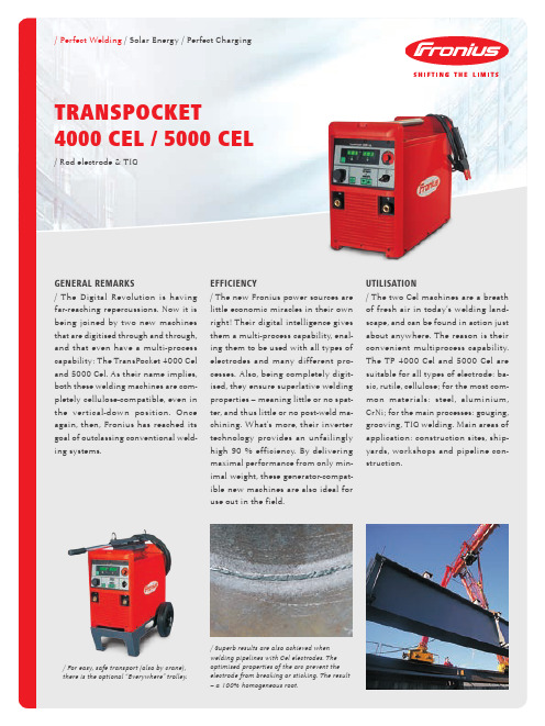
Fronius TransPocket 4000 Cel 和 5000 Cel 产品说明书
/ Perfect Welding / Solar Energy / Perfect Charging TRANSPOCKET 4000 CEL / 5000 CEL / Rod electrode & TIGGENERAL REMARKS/ The Digital Revolution is having far-reaching repercussions. Now it is being joined by two new machines that are digitised through and through, and that even have a multi-process capability: The TransPocket 4000 Cel and 5000 Cel. As their name implies, both these welding machines are com-pletely cellulose-compatible, even in the vertical-down position. Once again, then, Fronius has reached its goal of outclassing conventional weld-ing systems.EFFICIENCY/ The new Fronius power sources arelittle economic miracles in their ownright! Their digital intelligence givesthem a multi-process capability, enal-ing them to be used with all types ofelectrodes and many different pro-cesses. Also, being completely digit-ised, they ensure superlative weldingproperties – meaning little or no spat-ter, and thus little or no post-weld ma-chining. What‘s more, their invertertechnology provides an unfailinglyhigh 90 % efficiency. By deliveringmaximal performance from only min-imal weight, these generator-compat-ible new machines are also ideal foruse out in the field.UTILISATION/ The two Cel machines are a breathof fresh air in today‘s welding land-scape, and can be found in action justabout anywhere. The reason is theirconvenient multiprocess capability.The TP 4000 Cel and 5000 Cel aresuitable for all types of electrode: ba-sic, rutile, cellulose; for the most com-mon materials: steel, aluminium,CrNi; for the main processes: gouging,grooving, TIG welding. Main areas ofapplication: construction sites, ship-yards, workshops and pipeline con-struction./ For easy, safe transport (also by crane), there is the optional “Everywhere” trolley./ Superb results are also achieved when welding pipelines with Cel electrodes. The optimised properties of the arc prevent the electrode from breaking or sticking. The result – a 100% homogeneous root.a w 20Fronius International GmbH Froniusplatz 14600 Wels AustriaTelephone +43 7242 241-0Fax +43 7242 241-953940*****************Fronius UK LimitedMaidstone Road, Kingston Milton Keynes, MK10 0BD United KingdomTelephone +44 1908 512 300Fax +44 1908 512 329******************* Fronius USA LLC 6797 Fronius Drive Portage, IN 46368USATelephone +1 877 FRONIUS *********************Fronius Canada Ltd.2875 Argentia Road, Units 4,5 & 6 Mississauga, ON L5N 8G6CanadaTelephone +1 905 288-2100 Fax +1 905 288-2101 ************************www.fronius.ca/ Perfect Welding / Solar Energy / Perfect Chargingv04 Nov 2014 ENT e x t a n d i m a g e s c o r r e s p o n d t o t h e c u r r e n t s t a t e o f t e c h n o l o g y a t t h e t i m e o f p r i n t i n g . S u b j e c t t o m o d i f i c a t i o n s .A l l i n f o r m a t i o n i s w i t h o u t g u a r a n t e e i n s p i t e o f c a r e f u l e d i t i n g - l i a b i l i t y e x c l u d e d . C o p y r i g h t © 2011 F r o n i u s ™. A l l r i g h t s r e s e r v e d .Further information about all Fronius products and our global sales partners and representatives can be found at WE HAVE THREE DIVISIONS AND ONE PASSION: SHIFTING THE LIMITS OF POSSIBILITY./ Whether welding technology, photovoltaics or battery charging technology − our goal is clearly defined: to be the innovation leader. With around 3,000 employees worldwide, we shift the limits of what’s possible - our record of over 1,000 granted patents is testimony to this. While others progress step by step, we innovate in leaps and bounds. Just as we’ve always done. The responsible use of our resources forms the basis of our corporate policy.M ,06,0144,E N v 03 N o v 2014TP 4000 CELTP 4000 CELL MvTP 5000 CELTP 5000 CEL MvMains voltage 50 / 60 Hz 3 x 400 V 3 x 200 - 240 V 3 x 380 - 460 V3 x 400 V 3 x 200 - 240 V 3 x 380 - 460 VMains voltage tolerance± 15 %± 10 %± 15 %± 10 %Mains protection (slow-blow)35 A 3 x 200 - 240 V: 63 A 3 x 380 - 460 V: 35 A35 A 3 x 200 - 240 V: 63 A 3 x 380 - 460 V: 35 APrimary continuous power (100 % d.c.)12.9 kVA 12.9 kVA 16.3 kVA 16.3 kVA Cos phi 0.990.990.990.99Efficiency90%90%90%90%Welding current range Rod electrode WIG10 - 380 A 10 - 380 A 10 - 380 A 10 - 380 A10 - 480 A 10 - 480 A 10 - 480 A 10 - 480 AWelding current at10 min / 40°C 40 % d.c. 10 min / 40°C 60 % d.c. 10 min / 40°C 100 % d.c.380 A 360 A 320 A380 A 360 A 320 A480 A 420 A 360 A480 A 420 A 360 A Open-circuit voltage95 V 95 V 95 V 95 V Standardised working voltage Rod Electrode WIG20.4 - 35.2 V 14.5 - 33 V 20.4 - 35.2 V 14.5 - 33 V 20.4 - 39.2 V 14.5 - 38 V 20.4 - 39.2 V 14.5 - 38 V Maximum working voltage Rod Electrode 53 V (380 A)53 V (380 A)48 V (480 A)48 V (480 A)Degree of protectionIP 23IP 23IP 23Type of cooling / Insulation class AF / FAF / FAF / FAF / FDimensions L x W x H mm Inches 625 x 290 x 47524.63 x 11.43 x 18.72625 x 290 x 47524.63 x 11.43 x 18.72625 x 290 x 47524.63 x 11.43 x 18.72625 x 290 x 47524.63 x 11.43 x 18.72Weight36.1 kg 79.4 lb40 kg 88 lb37 kg 81.4 lb40.5 kg 89.1 lbTECHNICAL DATAALLGEMEINAnti-stick function Touchdown ignitionDigital weld process controlEnergy-saving inverter technology Earth leakage detectionV-down-compatible welding with Cel electrodesRemote-controllable Generator-compatible “Hot-Start” function Microprocessor control Thermostat-controlled fan TIG Comfort StopOvertemperature protectionINDICATION OFOperating mode Error codes “Hold” functionMains voltage monitoringWelding voltage (actual/guide value) Welding current (actual/guide value) OvertemperatureADjUSTAbLE PARAMETERSWelding current Arc-force Hot StartTP 4000 CEL TP 4000 CEL MV TP 5000 CEL TP 5000 CEL MVCHECKLIST。
- 1、下载文档前请自行甄别文档内容的完整性,平台不提供额外的编辑、内容补充、找答案等附加服务。
- 2、"仅部分预览"的文档,不可在线预览部分如存在完整性等问题,可反馈申请退款(可完整预览的文档不适用该条件!)。
- 3、如文档侵犯您的权益,请联系客服反馈,我们会尽快为您处理(人工客服工作时间:9:00-18:30)。
FRONIUS焊机保养维护手册
一主机:TPS焊机是世界上最先进的全数字化控制的逆变焊机。
1.对机器使用的基本要求:
A:焊接设备的输入电源电压必须是3相380V/AC 50Hz +/-10%,否则设备不能正常工作。
B:设备电源线与客户电源的连接处必须连接牢固,而且要选择正确的刀闸开关,否则将带来隐患,如:连接处出现打火,有可能引起火灾,产生后悔莫及的事件。
C:如果客户觉得电源输入线短,需加长时,必须注意:买与焊接设备输入线一样规格的线缆,必须是4芯线,并且有一条是黄/绿色为标志的地线。
否则在有些非专业人士接线时,很有可能将火线接到地线上去,这样将引起缺相,设备不能正常工作,有可能烧坏机器,产生严重的后果。
D:由于有的工厂的电网存在一些问题,如:地线和零线是同一根线,即:既是零线又是地线,但是一些低电压照明等用电器具,这就有可能引起隐患,因FRONIUS焊机有良好的接地,而且安装了地线过流检测器,如果地线的电流大于8A,则会出现故障报警,所以建议输入电源的地线和零线分开。
还有建议在机器的底部垫上绝缘物质。
E:设备必须放置安全位置,不被砸坏的地方,并具有良好的通风散热。
F:在使用设备前必须仔细检测输入电源线及连接处是否正常,是否有人动过。
焊接程序是否正常,各连接处是否有松动。
G:在保修期内,不要对焊接设备的任何部件进行随意拆卸,否则我们将视为人为损坏,不进行索赔保修处理。
二水冷系统:
水冷系统是大功率焊接设备必要的组成部件,它能将焊枪的热量充分的带走,使焊枪能够正常的工作,所以在进行焊接操作时,必须时刻注意水冷系统的工作情况。
1.正确安装水冷系统,与主机的连接一定要牢固,不能是接非接,否则可能带来隐患或危险的后果。
2.每次焊接时,必须检查水泵是否工作,流量是否正常,散热风扇是否工作,水循环是否正常,水冷系统的水量是否足够,即是否低于水位警戒线,如果低于,必须加入纯净水。
3.在焊接时必须时刻注意水冷系统是否有渗漏的地方,如果有,必须停止焊接,尽快解决问题。
如果不注意上述情况,将会带来严重的后果:水泵烧坏,焊枪烧坏,影响生产和增加维修成本。
三送丝系统:
VR4000送丝机是焊接的重要组成部分,在整个焊接过程中占有重要的地位。
但是如果操作人员对它不客气,那它也会对工作不客气,甚至会举行罢工,所以使用人员必须充分的了解送丝系统。
1.送丝轮的正确选择:在使用前必须了解所焊的材质,焊丝的材质,焊丝的直径,于是选择与之匹配的导丝轮,做到:严禁小脚穿大鞋或大脚穿小鞋。
否则将带来很大的麻烦。
2.送丝轮压力的调节:不同材质的焊丝,其送丝压力的调节不一样。
如:柔性材质的焊丝和硬质材质的焊丝其调节的方式和压力就不一样,对于柔性的焊丝,如:铝及铝合金或铜,铜合金的的焊丝,调节的力度不能太大,太大会将焊丝压得变形,造成送丝不畅,遵循的原则是:调节时做到前紧后松,导电嘴处如有堵力,最好让轮与焊丝能打滑,这样可以避免堵丝的现象。
对于硬质的焊丝,可以做到压力前后一致,尽可能的让焊丝顺畅送出。
3.送丝轮在使用一段时间后,必须仔细检查,看是否有破裂的现象,有无磨损严重的情况,如果出现必须及时更换,避免影响生产。
四焊枪
焊枪虽然腰纤嘴细,但作用不小。
所以在使用时必须正确的使用和爱护,否则会大大减少焊枪的使用寿命。
1.导丝管的正确安装和使用。
根据不同材质的焊丝选择不同的导丝管,如:铝及铝合金,铜及铜合金必须选用石墨纤维管或特氟龙管,其它材质的硬质焊丝必须用钢导丝管,更应注意:气冷和水冷的焊枪使用的导丝管不一样。
导丝管在使用一段时间后必须及时清理,尤其焊接铝或铝合金时,建议一天一清理,必须用高压气体将其内部的铝屑清理干净。
2.导丝管装入焊枪时必须将螺母拧紧,否则导丝管会随着焊丝往里送,于是易产生堵丝的情况。
3.导电嘴,喷嘴,绝缘环,分流器,它们属于焊枪的消耗品,但如果操作者能更爱护,可以延长其使用寿命。
导电嘴如果产生与焊丝打火,必须及时更换,否则影响送丝的稳定性。
喷嘴里如果有飞溅,必须马上清理,否则影响气体的送出和焊接的保护效果。
有的飞溅会在分流器上聚集,这时你应马上清理,否则影响气体的分配,影响焊接的保护效果,严重影响焊接的质量。
4.焊接时必须注意焊枪的弯曲度,尤其在焊接柔性材质时更应注意,如:铝,铝合金或铜及其铜合金,尽可能将焊枪拉直,保证送丝的顺畅性。
五中继线它是主机与送丝机之间的桥梁,在安装中继线时必须注意以下
问题:
1与送丝机连接时必须注意:a 主电缆的快速接头必须用力按顺时针的方向将其锁紧。
否则将会烧坏连接头,导致机器瘫痪。
B 水接头和气接头在安装时必须查看是
否有密封圈,如没有,将会产生漏水漏气的现象,从而影响焊接。
C 控制线的安
装,也必须按顺时针的方向将其拧紧,否则可能会烧坏插针或出现失控等问题。
2对于加长的中继线,更应注意上述情况。
因为加长中继线都是为了远距离作业,所以中继放的比较长,但施工现场工作环境很恶劣,所以操作者必须陪加注意中继线
的绕法和行走路线,不同的盘绕方式,构成的回路电感不同,于是可能引起焊接电
弧。
更不应拉着焊枪或抱着送丝机往前跑,不顾及中继线的运行,可能导致气管或
水管弯折,控制线拉断等情况,于是在下次施焊时出现水路和气路不通,送丝机不工作,形成恶性循环,更严重的可能导致焊枪或水泵的烧毁。
奥地利福尼斯(FRONIUS)数字化焊机
保
养
维
护
手
册。
